Embed Size (px)
Citation preview
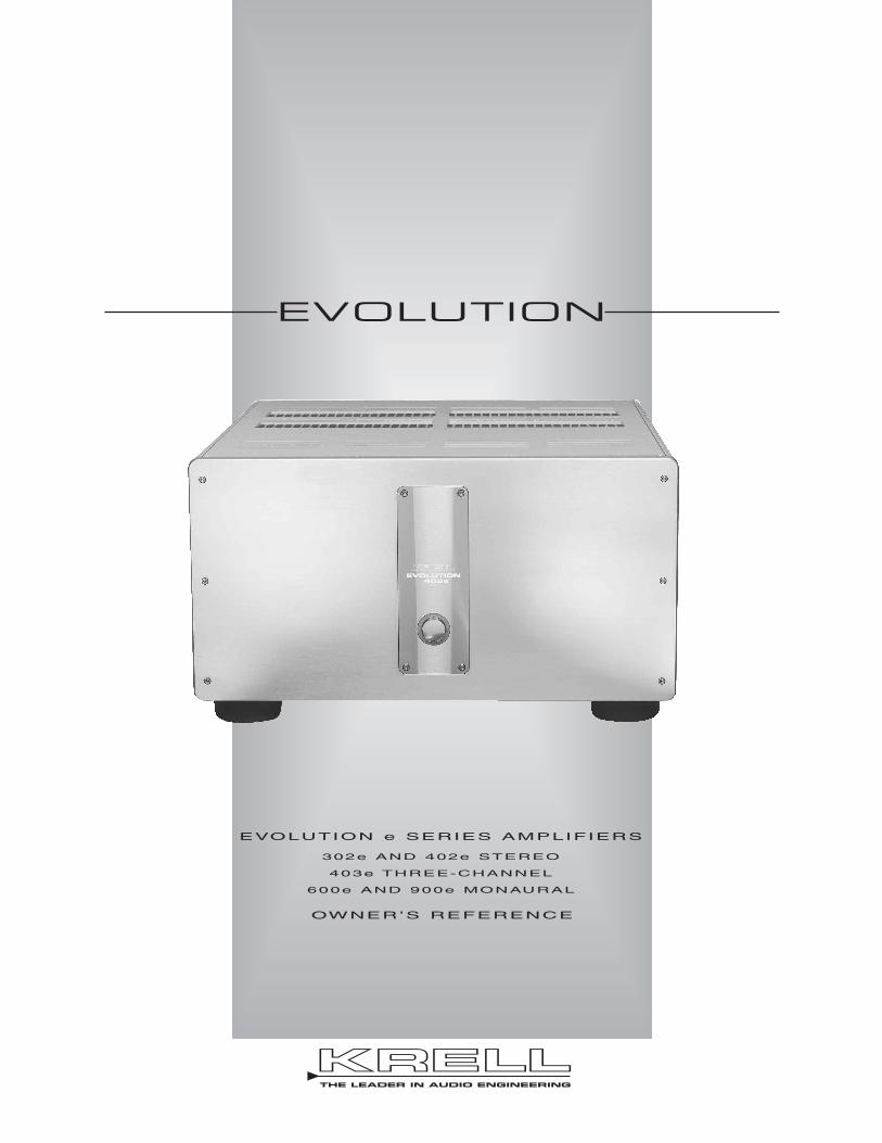
OWNER’S REFERENCE
EVOLUTION
EVOLUTION e SERIES AMPLIFIERS
302e AND 402e STEREO
403e THREE-CHANNEL
600e AND 900e MONAURAL
KRELLTHE LEADER IN AUDIO ENGINEERING

Evolution 302e, 402e, 403e, 600e and 900e Power Amplifiers Owner’s Reference, v01.0
Krell Industries, LLC45 Connair RoadOrange, CT 06477-3650 USA
This product complies with the EMC directive (89/336/EEC) and the low-voltage directive(73/23/EEC).
IMPORTANT SAFETY INSTRUCTIONS1. Read Instructions.
2. Keep these Instructions.
3. Heed all Warnings.
4. Follow all Instructions.
5. Do not use this apparatus near water.
6. Clean only with a dry cloth.
7. Do not install near any heat sources such as radiators, heat registers, stoves, or otherapparatus (including amplifiers) that produce heat.
8. Unplug this apparatus during lightning storms or when unused for long periods of time.
9. Refer all servicing to qualified service personnel. Servicing is required when the apparatushas been damaged in any way, such as a power-supply cord or plug is damaged, liquid hasbeen spilled or objects have fallen into the apparatus, the apparatus has been exposed torain or moisture, does not operate normally, or has been dropped.
10. An Evolution e Series amplifier must be placed on a firm, level surface where it is not exposedto dripping or splashing.
11. The ventilation grids on the top of every Evolution e Series amplifier, the ventilation grids on theback of the Evolution 302e and 400e amplifier, and the space underneath every Evolution eSeries amplifier must be unobstructed at all times during operation. Do not place flammablematerial above or beneath an Evolution e Series amplifier.
12. Before making connections to an Evolution e Series amplifier, ensure that the power is off andother components are in mute or stand-by mode. Make sure all cable terminations are of thehighest quality, free from frayed ends, short circuits, or cold solder joints. Be especially carefulwhen connecting to terminals marked which may have hazardous voltages on them duringoperation.
13. THERE ARE NO USER SERVICEABLE PARTS INSIDE AN EVOLUTION AMPLIFIER.
Please contact Krell if you have questions not addressed in this guide.
This product is manufactured in the United States of America. Krell® is a registered trademark of Krell Industries, LLC, and is restricted for use byKrell Industries, LLC, its subsidiaries, and authorized agents. CAST™, Evolution CAST™, and Krell Current Mode™ are trademarks of KrellIndustries, LLC. All other trademarks are registered to their respective companies.
© 2010 by Krell Industries, LLC. All rights reserved
TELL 203-298-4000FAX 203-891-2028E-MAIL [email protected] http://www.krellonline.com

3
ContentsList of Illustrations, page 4
A Letter from Krell, page 5
SECTION ONE: Evolution e Series Amplifier Features and Technology, page 6
Features, Revolutionary Krell CAST Technology,Definition of Terms
SECTION TWO: Unpacking and Placement, page 11
Opening the Evolution e Series Amplifier Shipping Carton
SECTION THREE: Anatomy of the Evolution e Series Amplifier, page 13
Front Panel Description, and Back Panel Description
SECTION FOUR: Connecting an Evolution e Series Amplifier to Your System, page 21
CAST Connections, Balanced Connections, Single-ended Connections, Evolution DC Protection Circuitry/Using Tube Preamplifiers, Connection Steps
SECTION FIVE: Evolution e Series Amplifier Operation, page 23
On/Off and Stand-by Operation
SECTION SIX:Troubleshooting System Noise, page 24
How to Evaluate e Series Amplifier Operation, Error Codes
SECTION SEVEN: Questions and Answers, page 26
WARRANTY, page 27
RETURN AUTHORIZATION PROCEDURE, page 29
SPECIFICATIONS, page 30
4
List of IllustrationsFigure 1, page 13
Evolution e Series Amplifier Front Panel
Figure 2, page 15
Evolution 302e Back Panel
Figure 3, page 16
Evolution 402e Back Panel
Figure 4, page 17
Evolution 403e Back Panel
Figure 5, page 18
Evolution e Series Monaural Amplifier Back Panel

5
A Letter from Krell Industries
Dear Audio Enthusiast,
Thank you for your purchase of a Krell Evolution e Series amplifier. No component in an audiosystem contributes more to the full range of musical expression than a power amplifier. Theseemingly impossible tasks of simultaneously conveying music's subtle emotional cues and intensedynamic passages rest squarely on its shoulders. In our quest for amplifiers that deliver absolutetruth in music reproduction, we present the Evolution e Series. This next generation of EvolutionAmplifiers, “e”, short for enhanced represent a defining moment in Krell design, joining awesomecurrent capability with a newly refined, ultra-linear circuit topology and environmentally friendlyoperation.
Krell amplifiers are best known for their ability to drive any loudspeaker to sound its best, withoutregard to impedance, efficiency, or driver style. It is linearity, an amplifier's ability to output an exactduplicate of the input signal, which is the ultimate measure of that amplifiers worth. Krell designstoward the common goal of linearity; through the rigorous application of Krell design principles thatfocus our efforts on four major performance factors: distortion, bandwidth, output impedance andcurrent capability. The Evolution e Series excels in each of these areas, delivering supreme accuracyfrom whisper level to astounding, awe inspiring amounts of power with grace and elegance.
BETTER SOUNDBuilding on the unique Active Cascode Topology foundation of the Evolution Series, the e Seriesamplifiers feature more precisely balanced current sharing among the seven sets of Active CascodeQuartets that make up the output stage. This greater precision elevates an already impressiveperformance envelope and provides greater amplifier reliability. Audible at all volume levels, thisimprovement is independent of load current. Although negative feedback in the Evolution amplifierswas already extremely low, a mere 14 dB---several orders of magnitude lower than othermanufacturers' power amplifiers, modifications to the feedback circuitry allow for more idealoperation completely independent of the signal level. The results are greatly enhanced inner detailand micro-dynamics with smoother high frequency response.
An intense upgrade to the power supply includes a number of improvements. There is now aseparate transformer for the digital power supplies. Not only does this facilitate greatly reducedpower consumption in standby, but it provides still better isolation between the digital and analogpower supplies. The high-current and high-voltage analog supplies have additional noise filtrationcircuitry to reduce high-frequency switching noise from the rectifiers. The high-current powersupplies also have more reservoir capacitance than before (anywhere from 10-50% more,depending upon the model). Finally, the power supply circuit board has been redesigned for betterisolation between the incoming AC power and the DC power supplies.
LESS HEAT, LOWER ENERGY CONSUMPTIONA new green standby mode reduces standby power draw dramatically. Standby power draw for allEvolution e Series amplifiers has been reduced to 2W. As an example, the Evolution 402e powerdraw drops to 2W from 260W as compared to the Evolution 402 - a reduction of 99% in energydraw and a huge drop in heat output. The power indicator ring now glows green to indicate the newenergy efficient mode.
We hope that you enjoy your new Evolution e Series amplifier.
Sincerely,
Krell Industries, LLC

6
SECTION ONEEvolution e Series Amplifier Features and Technology
This section describes the innovative features and technology of the Evolution e Seriesamplifiers, and defines CAST and other key terms used in this reference. There are fiveamplifier models in the Evolution e Series: the 302e Stereo Power Amplifier, the 402eStereo Power Amplifier, the 403e Three-channel Power Amplifier, the 600e Monaural PowerAmplifier, and the 900e Monaural Power Amplifier.
Features
Evolution e Series amplifiers are designed with a signal path that incorporates Krell CurrentMode and CAST circuitry.
All amplifiers feature massive power supplies. The power supply makes use of extensiveelectrical and magnetic shielding to keep radiated interference out of critical amplifiercircuits.
The Evolution 302e design utilizes a 3000 VA power supply. The Evolution 402e andEvolution 600e are equipped with a 4400 VA power supply, and the Evolution 403e andEvolution 900e house 6000 VA power supplies.
Internal high-current line conditioning circuitry filters RF noise on the AC mains, as well ascompensating for asymmetrical power waveforms and DC on the mains.
Advanced microprocessor control monitors critical operational parameters. Output current,DC offset, rail voltages, and operating temperature are all continuously monitored.

7
Revolutionary Krell CAST Technology
Current Audio Signal Transmission, termed CAST, is a revolutionary method ofconnecting analog audio components for unparalleled sonic performance. Innovativeengineering combines the new Krell CAST circuitry with existing Krell Current Modetechnology to create entire CAST systems that reproduce music with incredible range,tonality, and precision.
The Voltage Signal Transmissionand the Traditional Audio System
Traditionally, signal is transmitted in the voltage domain between two components. In anaudio system, each component is a discrete entity with unique characteristics that actupon the musical signal independently. Each component is unaware of the othercomponents in the system. The cables that connect the components also have their ownelectrical characteristics, which affect the sonic presentation of the entire system. CASTtransmission unifies individual components and interconnects into an electrically-linkedwhole. The original signal remains unaltered from source to speaker.
CAST Basics
Here is how a CAST audio system works. Internally, each CAST source transfers, oramplifies, current using Krell Current Mode circuitry. This current signal is then outputusing CAST circuitry. When the signal is received by a CAST input, Krell Current Modecircuitry again takes over until the signal reaches the loudspeaker. By maintaining themusical signal in the current domain from beginning to end, an entire CAST systembehaves as if it is one component. With CAST, circuit board properties and signaltransmission aberrations between components are eliminated. Cable impedances andtheir effects on the transmitted signal are non-existent.
How CAST and Krell Current Mode Interact
While CAST is a new method of transferring the musical signal between components, itsorigin stems from Krell Current Mode, the technology developed to transfer the musicalsignal within a component. CAST combined with Krell Current Mode circuitry takessignal transmission to the next evolutionary level. In essence,
continued
8
Krell Current Mode maintains the integrity of the signal within the component and CASTpreserves the transmitted signal between components. Together, CAST and Krell CurrentMode technologies unify separate Krell components into a single global circuit. KrellCurrent Mode technology enjoys bandwidth increases up to an order of magnitude greaterthan their voltage based counterparts. This dramatic increase in circuit bandwidth deliversnear perfection in the audible band that typically suffers from phase distortions in voltagecircuits.
CAST Cable Construction
A CAST system uses cables manufactured by Krell and other manufacturers speciallylicensed by Krell. Thin and flexible CAST cables are constructed with the same build qualityas other Krell components and are aesthetically matched to the components that Krellmanufactures. An all-metal body and locking connectors with gold contacts are part of thestandard no-compromise specification developed for every CAST cable made.
Evolution CAST
By employing revolutionary current mirror circuitry, the Evolution e Series amplifiercomponents raises CAST technology to another level. This advanced use of the technologyincreases the linearity, transient speed, and bandwidth of the Evolution components whilereducing the distortion by an order of magnitude.
The Best Musical Performance
When you operate a CAST system, you will hear significant improvements in everyperformance area: speed, precision, dynamic range, depth and width of the sound stage,transient impact, tonal balance, harmonic distortion, and more. The goal for CAST is thesame company goal used for all Krell products. Krell strives for the delivery of the bestperformance of a musical event for you, using the full expression of technology to date.
(SECTION ONE: Evolution e Series Amplifier Features and Technology continued)
9
Definition of TermsThe following are definitions of key terms used in this owner’s reference:
Inputs and Outputs
Balanced A symmetrical input or output circuit that has equal impedance from both input terminals to a common ground reference point. The industry standard for professional andsound recording installations, balanced connections have 6 dB more gain than single-endedconnections and allow the use of long interconnect cables. Balanced connections arecompletely immune to induced noise from the system or the environment.
CAST and Evolution CASTKrell Current Audio Signal Transmission, or CAST, is a proprietary Krell circuit technologyfor connecting analog components, transmitting the audio waveform between componentsin the current domain rather than in the voltage domain. The speed and bandwidth providedby Krell CAST and its circuitry update, Evolution CAST, yield accurate, realistic musicreproduction, enabling connected components to perform as if they are all part of a singlecircuit. CAST and Evolution CAST are balanced connections, and reject induced noise.
Single-endedA two-wire input or output circuit. Single-ended connections are not recommended forconnections requiring long cable runs. Use care when using single-ended connections,because the ground connection is made last and broken first. Turn the system off/on prior tomaking or breaking single-ended connections.
Operation
OffWhen the power status indicator is not illuminated, the amplifier is off.
Stand-byA low-power-consumption status that keeps the audio and power supply circuits at idle. Thepower status indicator illuminates in green. Green is the default standby color and indicatesan ultra low power draw of 2 watts. An optional red standby mode is available which keepsthe input and driver stages continuously powered. Krell recommends leaving the amplifier instand-by mode when it is not playing music.
OperationWhen the power button is pressed, and the power status indicator is illuminated in blue, theamplifier is in operational mode and ready to play music.
continued

10
Technology
Active Cascode TopologyA unique circuit technique that minimizes distortion by applying from 2 to 3 times moreactive devices to each gain stage thereby reducing the load on individual devices andimproving circuit-wide linearity.
Krell Current ModeA proprietary Krell circuit topology in which the audio gain stages of a component operatein the current domain rather than the voltage domain. This unique technology provides thecomponent with exceptional speed, and a wide bandwidth.
(SECTION ONE: Definition of Terms continued)
11
Unpacking and PlacementThis section describes the procedures for safely unpacking and placing your Evolution eSeries amplifier. The amplifier and accessories are shipped in 1 carton. The dimensions ofthe amplifier are shown in the specifications section starting on page 30.
Two people are needed to remove the Evolution e Series amplifier from its shipping boxsafely and easily.
Opening the Evolution e Series Amplifier Shipping Carton
1. Open the shipping carton and remove the top layer of foam. The carton contains these items:
1 Evolution e Series amplifier chassis1 20 amp AC power cord1 12 VDC (12 V trigger) cable1 Packet containing the Quick Setup Guide and the warranty registration card
2. Orient the shipping box so that one person stands at the front of the amplifier and oneperson stands at the back of the amplifier. Both people need to grab a pair of thecardboard handle cutouts (one pair located at the front of the amplifier and one pairlocated at the back of the amplifier) and simultaneously lift the amplifier straight up, outof the carton. Bend and lift with your knees, not your back.
3. Place the amplifier in a safe location, and remove the protective plastic wrapping.
NoteSave all packing materials. If you need to ship the Evolution e Series amplifier in future, repack the
unit in its original packaging to prevent shipping damage.
SECTIONTWO
continued
12
PlacementBefore you install an Evolution e Series amplifier into your system, please follow theguidelines in this section to select a location for your component. This will facilitate a clean,trouble-free installation.
Place the amplifier on a firm, level surface, away from excessive heat, humidity, ormoisture. Each Evolution e Series amplifier requires at least two inches (5 cm) of clearanceon each side and at least eight inches (20 cm) of clearance above the component toprovide adequate ventilation.
If you place the amplifier in a closed cabinet, you may need to modify shelf spacing or usesmall fans to increase ventilation. When the front and back of a cabinet are open, the airspace between the chassis and shelf must be unobstructed.
Place the amplifier(s) as close to the loudspeakers as possible. While Evolution CASTtechnology permits long interconnect cable lengths, keep loudspeaker cable lengths to aminimum.
AC Power Guidelines
The Evolution e Series amplifier requires a dedicated AC circuit rated at a minimum of 20amps. Do not use extension cords, multiple AC adapters, or AC power strips.
NoteDo not operate the Evolution e Series amplifiers with any device designed to alter or condition
AC power.
(SECTION TWO: Unpacking and Placement continued)
1313
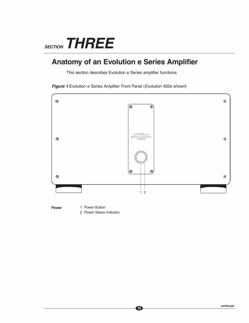
SECTION THREEAnatomy of an Evolution e Series Amplifier
This section describes Evolution e Series amplifier functions.
Figure 1 Evolution e Series Amplifier Front Panel (Evolution 402e shown)
1 Power Button2 Power Status Indicator
Power
continued
EVOLUTIONEVOLUTION402e402e
1 2

1414
Front Panel DescriptionSee Figure 1 on the previous page
Evolution e Series amplifier front panel functions are described below:
Power1 Power Button
Press this button to place the Evolution e Series amplifier in operational mode.
2 Power Status IndicatorThe power status indicator is illuminated in either green or red when the amplifier is instand-by mode. The indicator illuminates in blue when the amplifier is in operationalmode. If there is no illumination, please check the following items:
—The power cord is connected to the amplifier
—The power cord is plugged into a live AC power supply
—The back panel power breaker switch (10) is set to the on position
—The back panel backlight switch (8) is set to the on/ext position
—There is no 12 VDC controller connected to the EXT IN connector
(SECTION THREE: Anatomy of an Evolution e Series Amplifier continued)
continued
15
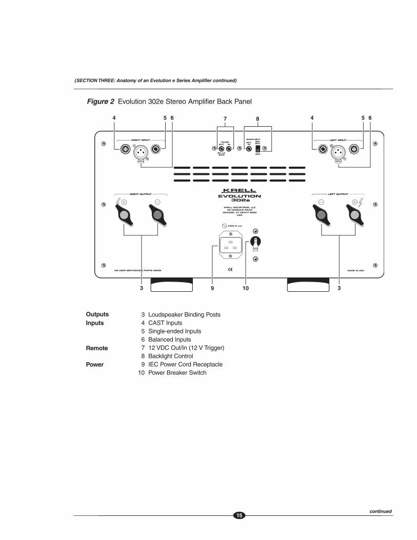
Figure 2 Evolution 302e Stereo Amplifier Back Panel
3 Loudspeaker Binding Posts4 CAST Inputs5 Single-ended Inputs6 Balanced Inputs7 12 VDC Out/In (12 V Trigger)8 Backlight Control9 IEC Power Cord Receptacle
10 Power Breaker Switch
InputsOutputs
Remote
Power
continued
KRELL INDUSTRIES, LLC45 CONNAIR ROAD
ORANGE, CT 06447-3650USA
e
3400 W max
(SECTION THREE: Anatomy of an Evolution e Series Amplifier continued)
16
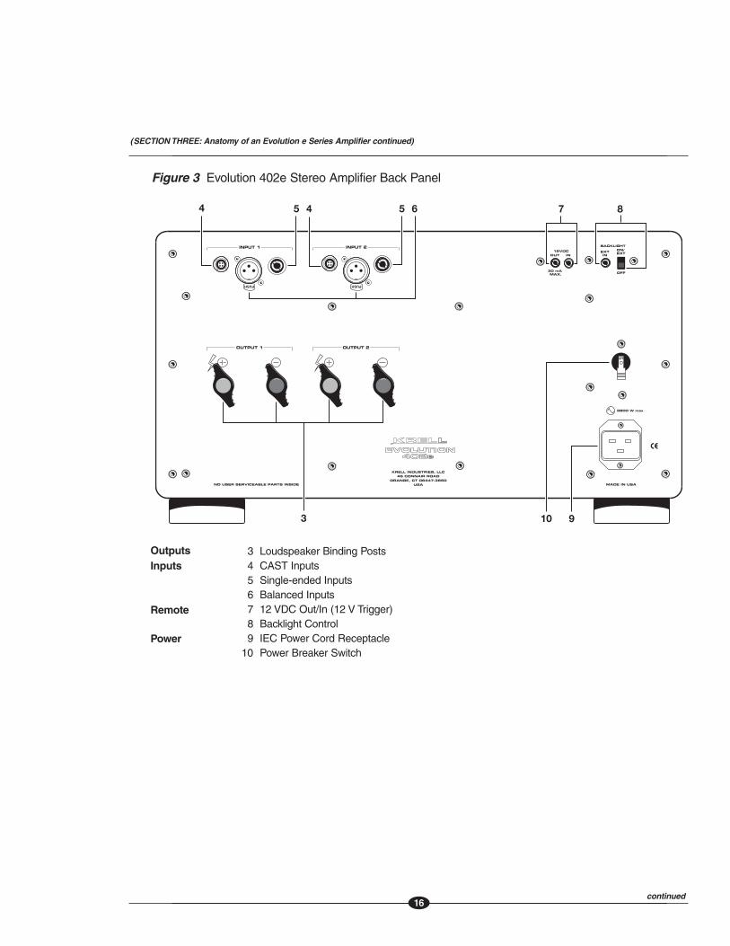
Figure 3 Evolution 402e Stereo Amplifier Back Panel
3 Loudspeaker Binding Posts4 CAST Inputs5 Single-ended Inputs6 Balanced Inputs7 12 VDC Out/In (12 V Trigger)8 Backlight Control9 IEC Power Cord Receptacle
10 Power Breaker Switch
InputsOutputs
Remote
Power
e
KRELL INDUSTRIES, LLC45 CONNAIR ROAD
ORANGE, CT 06447-3650USA
3800 W max
44 5 5 6
3
7 8
10 9
(SECTION THREE: Anatomy of an Evolution e Series Amplifier continued)
continued
1717
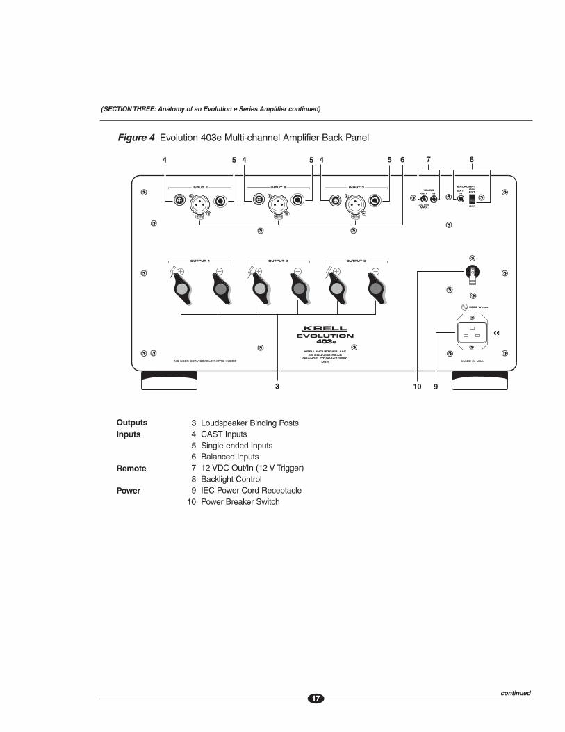
Figure 4 Evolution 403e Multi-channel Amplifier Back Panel
3 Loudspeaker Binding Posts4 CAST Inputs5 Single-ended Inputs6 Balanced Inputs7 12 VDC Out/In (12 V Trigger)8 Backlight Control9 IEC Power Cord Receptacle
10 Power Breaker Switch
InputsOutputs
Remote
Power
(SECTION THREE: Anatomy of an Evolution e Series Amplifier continued)
e
KRELL INDUSTRIES, LLC45 CONNAIR ROAD
ORANGE, CT 06447-3650USA
5000 W max
continued
18
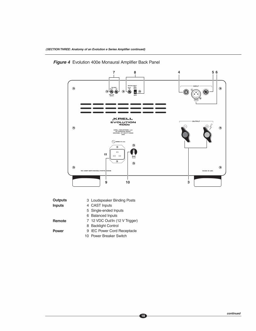
Figure 4 Evolution 400e Monaural Amplifier Back Panel
3 Loudspeaker Binding Posts4 CAST Inputs5 Single-ended Inputs6 Balanced Inputs7 12 VDC Out/In (12 V Trigger)8 Backlight Control9 IEC Power Cord Receptacle
10 Power Breaker Switch
InputsOutputs
Remote
Power
(SECTION THREE: Anatomy of an Evolution e Series Amplifier continued)
e
LLC
2500 W max
continued
1919
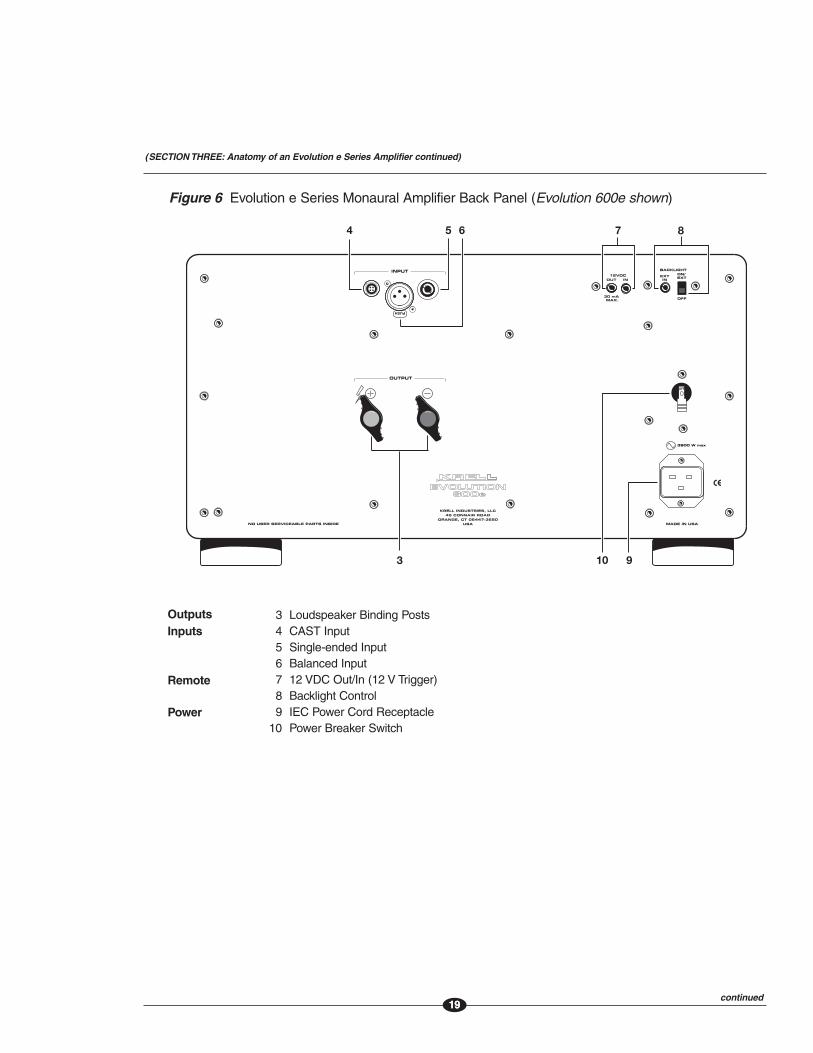
Figure 6 Evolution e Series Monaural Amplifier Back Panel (Evolution 600e shown)
3 Loudspeaker Binding Posts4 CAST Input5 Single-ended Input6 Balanced Input7 12 VDC Out/In (12 V Trigger)8 Backlight Control9 IEC Power Cord Receptacle
10 Power Breaker Switch
InputsOutputs
Remote
Power
KRELL INDUSTRIES, LLC45 CONNAIR ROAD
ORANGE, CT 06447-3650USA
e
3800 W max
4 5 6
3
7 8
10 9
continued
(SECTION THREE: Anatomy of an Evolution e Series Amplifier continued)
20
Back Panel DescriptionSee Figure 2, 3, and 4 on the previous pages
The amplifier back panel provides access to the input and output connections, 12 V triggerinputs and outputs, and the AC power connection and switch. Back panel features and theirdescriptions follow:
Outputs3 Loudspeaker Binding Posts (one pair per channel)
Each channel has one positive and one negative binding post. They accept spade lugs only.
Inputs4 CAST Inputs (one per channel)
These are CAST inputs with 4-pin bayonet connectors, for use with Krell CAST-equipped preamplifiers and components.
5 Single-ended Inputs (one per channel)These are single-ended analog inputs with RCA connectors.
6 Balanced Inputs (one per channel)These are balanced analog inputs with XLR connectors.
(SECTION THREE: Anatomy of an Evolution e Series Amplifier continued)
continued
21
Remote Connections7 12 VDC In/Out (12 V Trigger)
The 12 V trigger allows you to turn the Evolution e Series amplifier on or to stand-byfrom other components.Out. The output sends 12 VDC (12 V trigger) power on/off signals to other Krellcomponents and other devices that incorporate a 12 V trigger, allowing whole systemsor parts of systems to be easily controlled remotely. Mono 3.5 mm connectors are usedin the following configuration: Tip = +12 V, Sleeve = GND.
NotesWhen an Evolution e Series amplifier is in the operational mode, the 12 V trigger provides 12 Volts
of DC output. When the amplifier is in the stand-by mode or off, the DC output is 0 Volts. A
maximum of 30 mA is available from the 12 V trigger output.
Consult the owner's reference of the components used in a custom installation to take full
advantage of the remote capabilities of an Evolution e Series amplifier.
8 Backlight ControlExt In. Connect a 12 V trigger to the Ext In input connector to turn off the power statusindicator (2) using a remote control. The switch must be set to On/Ext, in order for thisto function (see below).
On/Ext. This activates the power status indicator. (This is the factory default position.)
Off. This turns off the power status indicator, during normal operation. The power statusindicator remains illuminated for ten seconds after the power button is pressed.
Power9 IEC Power Cord Receptacle
The power receptacle is for use with the provided 20 amp AC power cord. Use only thepower cord supplied with your Evolution e Series amplifier.
10 Power Breaker SwitchPlace this switch in the up position to put the amplifier in stand-by mode. Place theswitch in the down position to turn off the amplifier.
(SECTION THREE: Anatomy of an Evolution e Series Amplifier continued)
22
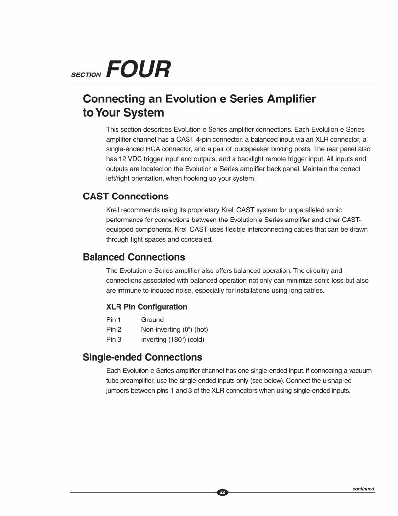
SECTION FOURConnecting an Evolution e Series Amplifier to Your System
This section describes Evolution e Series amplifier connections. Each Evolution e Seriesamplifier channel has a CAST 4-pin connector, a balanced input via an XLR connector, asingle-ended RCA connector, and a pair of loudspeaker binding posts. The rear panel alsohas 12 VDC trigger input and outputs, and a backlight remote trigger input. All inputs andoutputs are located on the Evolution e Series amplifier back panel. Maintain the correctleft/right orientation, when hooking up your system.
CAST ConnectionsKrell recommends using its proprietary Krell CAST system for unparalleled sonicperformance for connections between the Evolution e Series amplifier and other CAST-equipped components. Krell CAST uses flexible interconnecting cables that can be drawnthrough tight spaces and concealed.
Balanced ConnectionsThe Evolution e Series amplifier also offers balanced operation. The circuitry andconnections associated with balanced operation not only can minimize sonic loss but alsoare immune to induced noise, especially for installations using long cables.
XLR Pin Configuration
Pin 1 GroundPin 2 Non-inverting (0O) (hot)Pin 3 Inverting (180O) (cold)
Single-ended ConnectionsEach Evolution e Series amplifier channel has one single-ended input. If connecting a vacuumtube preamplifier, use the single-ended inputs only (see below). Connect the u-shap-edjumpers between pins 1 and 3 of the XLR connectors when using single-ended inputs.
continued

23
Evolution DC Protection Circuitry/Using Tube PreamplifiersThe high DC output of tube preamplifiers may exceed the active DC protection circuitry ofthe Evolution e Series amplifiers. Excessive DC level in a signal can damage amplifiers,loudspeakers, or both. The single-ended inputs of the Evolution e Series amplifiers arecapacitor-coupled and DC does not pass through. Therefore, if connecting a tubepreamplifier, use the single-ended inputs only. For more information about DC protectioncircuitry features, see Error Codes on page 25.
Connection StepsPosition the amplifier where you intend to use it in your system.
The following steps describe how to connect an Evolution e Series amplifier to your system:
1. Turn off all power sources and components before connecting inputs and outputs.
2. Neatly arrange and organize wiring to and from the Evolution e Series amplifier and allcomponents. Separate AC wires from audio cables to prevent hum or other unwantednoise from being introduced into the system.
3. Connect the outputs of your preamplifier to the appropriate CAST (4), balanced (6), orsingle-ended inputs (5) on the Evolution e Series amplifier.
NoteConnect the u-shaped jumpers between pins 1 and 3 of the XLR connectors when using single-
ended inputs.
4. Connect the loudspeaker cables to the loudspeaker binding posts (7) on the Evolution eSeries amplifier. The binding posts accept spade lugs only. Take care to observe thecorrect polarity when making connections: The positive (+) output connects to thepositive input of the loudspeaker. The negative (-) output connects to the negative inputof the loudspeaker.
5. Connect the supplied AC power cord to the AC power cord receptacle (9).
6. Plug the AC power cord into AC power.
NoteUse only the power cord provided with the Evolution e Series amplifier to make the connection to
AC power. Operation with a power cord other than the one supplied by Krell could induce noise,
limit current, or otherwise impair the ability of the amplifier to perform optimally.
(SECTION FOUR: Connecting an Evolution e Series Amplifier to Your System continued)

24
Evolution e Series Amplifier OperationThe Evolution e Series amplifiers are easy to operate.
IMPORTANTWhen powering up any system, turn the amplifier on last.When powering down, turn it off first.This will prevent any turn-on and turn-off thumps in your loudspeakers.
Always mute or fully attenuate the preamplifier level when switching sources. Do not changeinput connections to the amplifier when the amplifier is on.
Krell amplifiers have large reserves of clean power that can safely drive loudspeakers to highersound pressure levels than other amplifiers. Use care when setting high playback levels, andlower the volume level at the first sign of loudspeaker distress.
On/Off and Stand-by Operation1. Move the back panel power breaker switch (10) to the up position to place the amplifier
in stand-by mode. The power status indicator (2) illuminates in green. Green is thedefault standby color and indicates an ultra low power draw of 2 watts. An optional redstandby mode is available which keeps the input and driver stages continuouslypowered. To engage the red standby power mode, move the power breaker switch (10)to the down position, and while pressing the silver power button (1) on the amplifierfront panel, return power breaker switch (10) to the up position. Repeat the procedure toreturn to the green operating mode.
2. Press the silver power button (1) on the amplifier front panel. The power status indicator(2) illuminates in blue.
The initial power-up phase lasts approximately 30 seconds from the moment the backpanel power breaker switch is placed in the up position. If the power button is pressedduring this period, the power status indicator flashes blue for the remainder of the initialpower-up phase. When the initial power-up phase is complete, the power indicatorilluminates in blue and is no longer flashing. The amplifier is in the operational mode.
3. With the preamplifier muted or its volume completely lowered, select a source.
4. Increase the volume control to the desired listening level.
5. To return the amplifier to stand-by, press the power button on the front panel. The powerstatus indicator turns green or red, and the amplifier is in the stand-by mode.
It is now safe to place the rest of the system in stand-by.
Powering OffKrell recommends leaving Evolution e Series amplifiers in the stand-by mode betweenlistening sessions. Turn the amplifier off using the power breaker switch (10), anddisconnect the amplifier from AC power when the system is not being used for an extendedperiod of time.
SECTION FIVE

25
Troubleshooting System NoiseAC grounding becomes critical when connecting high-performance audio components.When you mix and match high-performance audio components, each with its own groundpotential, a low frequency hum may occur in one or both loudspeakers. This often occurswhen introducing a new component into a system.
If this happens when you place the Evolution e Series amplifier into your system, followthese simple troubleshooting steps.
Note
During these steps, the back panel power breaker switch remains in the on position.
1. Check that all input and output connections are of sound construction.
2. With the amplifier in stand-by mode, remove the interconnect cables, then turn theamplifier on. If the hum disappears, turn the amplifier into stand-by mode again, andreinsert one of the interconnect cables. Turn the amplifier back on. Repeat this processfor each cable.
3. If the hum reappears with one or both interconnect cables reinserted, the cable needsto be checked.
4. If the interconnect cables are sound, you may be experiencing a ground loop. Pleasecontact your authorized Krell dealer, distributor, or Krell for suggestions on how toeliminate the ground loop.
How to Evaluate Amplifier OperationThe amplifiers are protected by a series of non-intrusive circuits that constantly evaluatethe amplifier’s operation. This circuitry protects against damaging DC input or output, andshort circuits. The protection circuitry in an Evolution e Series amplifier is designed toprevent damage to the amplifiers or loudspeakers caused by other defective components,faulty wiring, system mishandling, or amplifier failure.
SECTION SIX
continued
26
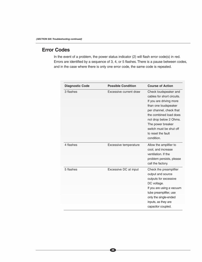
Error CodesIn the event of a problem, the power status indicator (2) will flash error code(s) in red.Errors are identified by a sequence of 3, 4, or 5 flashes. There is a pause between codes,and in the case where there is only one error code, the same code is repeated.
Diagnostic Code Possible Condition Course of Action
3 flashes Excessive current draw Check loudspeaker and
cables for short circuits.
If you are driving more
than one loudspeaker
per channel, check that
the combined load does
not drop below 2 Ohms.
The power breaker
switch must be shut off
to reset the fault
condition.
4 flashes Excessive temperature Allow the amplifier to
cool, and increase
ventilation. If the
problem persists, please
call the factory.
5 flashes Excessive DC at input Check the preamplifier
output and source
outputs for excessive
DC voltage.
If you are using a vacuum
tube preamplifier, use
only the single-ended
inputs, as they are
capacitor coupled.
(SECTION SIX:Troubleshooting continued)

27
Questions and AnswersQ. Should I leave my Evolution e Series amplifier on at all times?
A. For maximum amplifier performance, leave the back panel power breaker switch on atall times. This places the amplifier in stand-by mode. Evolution e Series amplifiers aredesigned to be powered on and off from stand-by, using the front panel power button.This eliminates “cold start” degradation. The amplifier will operate at full performancewithin minutes.
Q. When I turn on the amplifier there is a loud hum through the loudspeakers.What should I do?
A. When a new component is introduced, a low frequency hum may occur in one or bothloudspeakers. Check all input and output connections and cables, making sure they areof sound construction. See Troubleshooting System Noise, on page 24. If theinterconnects and cables are sound, you may be experiencing a ground loop. This canoften be easily eliminated. Please contact your authorized Krell dealer, distributor, orKrell for suggestions on how to solve this problem.
Q. My loudspeakers are rated for 150 Watts. Are the Evolution models too powerful forthem?
A. No. A loudspeaker seldom is damaged from overdriving. More often, damage occurswhen an amplifier that lacks sufficient power is asked to handle heavy demandsituations such as high playback levels. These amplifiers may have very high 8 Ohmpower ratings, but in heavy demand situations they can be driven into clipping (in whichhigh power, high frequency harmonics go to the loudspeakers, due to loss of amplifierpower). Clipping can damage loudspeakers. Avoid damage to your loudspeakers byreviewing your loudspeaker’s specifications, and exercise caution in heavy demandsituations.
SECTION SEVEN

28
WarrantyKrell products have a limited warranty. Amplifiers, preamplifiers, preamp/processors, andreceivers carry a limited warranty of five years from date of purchase or six years from date ofmanufacture for parts and labor on circuitry. Loudspeakers carry a limited warranty of five yearsfrom date of purchase or six years from date of manufacture for parts and labor. CD and DVDplayers carry a limited warranty of five years from date of purchase or six years from date ofmanufacture for parts and labor on circuitry, and three years for parts and labor on mechanicalparts. Should the product fail to perform at any time during the warranty, Krell will repair it at nocost to the owner, except as set forth in this warranty.This warranty does not apply to damagecaused by acts of God or nature.This warranty shall be in lieu of any other warranty, expressedor implied, including, but not limited to, any implied warranty of merchantability or fitness for aparticular purpose.There are no warranties which exceed beyond those described in thisdocument, if the product does not perform as warranted herein, the owner's sole remedy shallbe repair. In no event will Krell be liable for incidental or consequential damages arising frompurchase, use, or inability to use the product, even if Krell has been advised of the possibility ofsuch damages.
IMPORTANTThe single-ended inputs on the Evolution e Series amplifiers are cap-coupled. Use theseinputs whenever you are connecting a tube preamplifier.
Proof of purchase in the form of a bill of sale or receipted invoice substantiating that theproduct is within the warranty period must be presented to obtain warranty service. Thewarranty begins on the date of the original retail purchase, as noted on the bill of sale orreceipted invoice from an authorized Krell dealer or distributor. Previously owned equipment,when re-purchased from an authorized Krell dealer or distributor, has the balance of theoriginal warranty, based on the original date of manufacture. Krell dealers and distributorsare not authorized to sell current products on the Internet. Current products purchased viathe Internet do not have any transferrable warranty.
The warranty for a Krell product is valid only in the country to which it was originally shipped,through the authorized Krell distributor for that country, and at the factory. There may berestrictions on or changes to the Krell warranty because of regulations within a specificcountry. Please check with your distributor for a complete understanding of the warranty inyour country.
continued

29
If the product is serviced by a distributor who did not import the unit, there may be a chargefor service, even if the product is within the warranty period.
Freight to the factory is your responsibility. Return freight within the United States (U.S.A.) isincluded in the warranty. If you have purchased your Krell product outside the U.S.A. andwish to have it serviced at the factory, all freight and associated charges to the factory areyour responsibility. Krell will pay return freight to the U.S.A.-based freight forwarder of yourchoice. Freight and other charges to ship the product from the freight forwarder to you arealso your responsibility.
Krell is not responsible for any damage incurred in transit. Krell will file claims for damagesas necessary for a product damaged in transit to the factory.You are responsible for filingclaims for shipping damages during the return shipment.
Krell does not supply replacement parts and/or products to the owner of the product.Replacement parts and/or products will be furnished only to the distributor performingservice on this product on an exchange basis only; any parts and/or products returned toKrell for exchange become the property of Krell.
No expressed or implied warranty is made for any Krell product damaged by accident,abuse, misuse, natural or personal disaster, or unauthorized modification.
Any unauthorized voltage conversion, disassembly, component replacement,perforation of chassis, updates, or modifications performed to the product will voidthe warranty.
The operating voltage of the product is determined by the factory and can only be changedby an authorized Krell distributor or at the factory. The voltage for this product in the U.S.A.cannot be changed until six months from the original purchase date.
In the event that Krell receives a product for warranty service that has been modified in anyway without Krell authorization, all warranties on that product will be void. The product will bereturned to original factory layout specifications at the owner’s expense before it is repaired.All repairs required after the product has been returned to original factory specifications willbe charged to the customer, at current parts and labor rates.
All operational features, functions, and specifications and policies are subject to changewithout notification.
To register your product for warranty benefits, please complete and return theWarranty Registration Card enclosed in the shipping box within 15 days ofpurchase.Thank you.

30
Return Authorization ProcedureHow to Expedite Service
If you believe there is a problem with your component, please contact your dealer,distributor, or the Krell factory to discuss the problem before you return the componentfor repair. To expedite service, you may wish to complete and e-mail the Service RequestForm in the Service section of our website at:
http://www.krellonline.com
How to Return a Product
To return a product to Krell, please follow this procedure so that we may serve you better:
1. Obtain a Return Authorization Number (R/A number) and shipping address from the Krell Service Department.
2. Insure and accept all liability for loss or damage to the product during shipment to the Krell factory and ensure that all freight (shipping) charges are prepaid.
The product may also be hand delivered if arrangements with the Service Department havebeen made in advance. Proof of purchase will be required for warranty validation at thetime of hand delivery.
IMPORTANTUse the original packaging to ensure the safe transit of the product to the factory, dealer, ordistributor. Krell may, at its discretion, return a product in new packaging and bill the owner forsuch packaging if the product received by Krell was boxed in nonstandard packaging or if theoriginal packaging was so damaged that it was unusable. If Krell determines that newpackaging is required, the owner will be notified before the product is returned.
How to Purchase Additional Packing
To purchase additional packing, please contact your authorized Krell dealer, distributor, orthe Krell Service Department for assistance.
30
To contact the Krell Service Department:
TELL 203-298-4020, Monday-Friday9:00 AM to 5:00 PM EST
FAX 203-795-2287E-MAIL [email protected]
WEBSITE http://www.krellonline.com
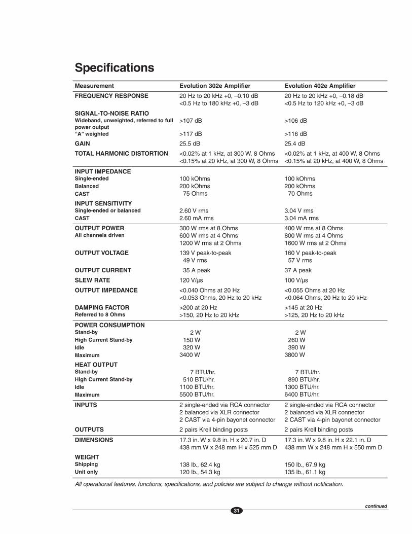
SpecificationsMeasurement Evolution 302e Amplifier Evolution 402e Amplifier
FREQUENCY RESPONSE 20 Hz to 20 kHz +0, –0.10 dB <0.5 Hz to 180 kHz +0, –3 dB
20 Hz to 20 kHz +0, –0.18 dB <0.5 Hz to 120 kHz +0, –3 dB
SIGNAL-TO-NOISE RATIOWideband, unweighted, referred to fullpower output“A” weighted
>107 dB
>117 dB
>106 dB
>116 dB
GAIN 25.5 dB 25.4 dB
TOTAL HARMONIC DISTORTION <0.02% at 1 kHz, at 300 W, 8 Ohms <0.15% at 20 kHz, at 300 W, 8 Ohms
<0.02% at 1 kHz, at 400 W, 8 Ohms <0.15% at 20 kHz, at 400 W, 8 Ohms
INPUT IMPEDANCESingle-endedBalancedCAST
100 kOhms 200 kOhms
75 Ohms
100 kOhms 200 kOhms
70 Ohms
INPUT SENSITIVITYSingle-ended or balanced CAST
2.60 V rms2.60 mA rms
3.04 V rms3.04 mA rms
OUTPUT POWERAll channels driven
300 W rms at 8 Ohms 600 W rms at 4 Ohms 1200 W rms at 2 Ohms
400 W rms at 8 Ohms 800 W rms at 4 Ohms1600 W rms at 2 Ohms
OUTPUT VOLTAGE 139 V peak-to-peak 49 V rms
160 V peak-to-peak 57 V rms
OUTPUT CURRENT 35 A peak 37 A peak
SLEW RATE 120 V/µs 100 V/µs
OUTPUT IMPEDANCE <0.040 Ohms at 20 Hz <0.053 Ohms, 20 Hz to 20 kHz
<0.055 Ohms at 20 Hz <0.064 Ohms, 20 Hz to 20 kHz
DAMPING FACTORReferred to 8 Ohms
>200 at 20 Hz >150, 20 Hz to 20 kHz
>145 at 20 Hz >125, 20 Hz to 20 kHz
POWER CONSUMPTIONStand-byHigh Current Stand-byIdleMaximum
2 W150 W 320 W
3400 W
2 W260 W 390 W
3800 W
HEAT OUTPUTStand-byHigh Current Stand-byIdleMaximum
7 BTU/hr.510 BTU/hr.
1100 BTU/hr.5500 BTU/hr.
7 BTU/hr.890 BTU/hr.
1300 BTU/hr.6400 BTU/hr.
INPUTS 2 single-ended via RCA connector 2 balanced via XLR connector 2 CAST via 4-pin bayonet connector
2 single-ended via RCA connector 2 balanced via XLR connector 2 CAST via 4-pin bayonet connector
OUTPUTS 2 pairs Krell binding posts 2 pairs Krell binding posts
DIMENSIONS 17.3 in. W x 9.8 in. H x 20.7 in. D 438 mm W x 248 mm H x 525 mm D
17.3 in. W x 9.8 in. H x 22.1 in. D 438 mm W x 248 mm H x 550 mm D
WEIGHTShippingUnit only
138 lb., 62.4 kg120 lb., 54.3 kg
150 lb., 67.9 kg135 lb., 61.1 kg
All operational features, functions, specifications, and policies are subject to change without notification.
31continued
32
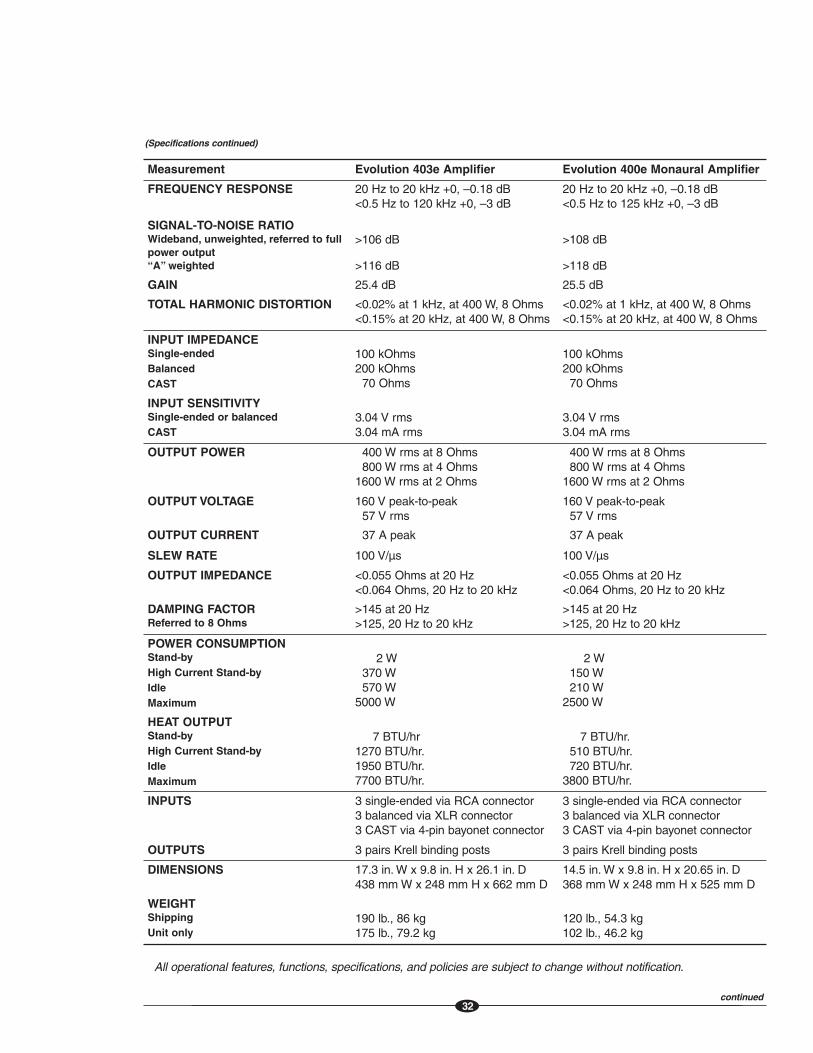
(Specifications continued)
Measurement Evolution 403e Amplifier Evolution 400e Monaural Amplifier
FREQUENCY RESPONSE 20 Hz to 20 kHz +0, –0.18 dB<0.5 Hz to 120 kHz +0, –3 dB
20 Hz to 20 kHz +0, –0.18 dB <0.5 Hz to 125 kHz +0, –3 dB
SIGNAL-TO-NOISE RATIOWideband, unweighted, referred to fullpower output“A” weighted
>106 dB
>116 dB
>108 dB
>118 dB
GAIN 25.4 dB 25.5 dB
TOTAL HARMONIC DISTORTION <0.02% at 1 kHz, at 400 W, 8 Ohms <0.15% at 20 kHz, at 400 W, 8 Ohms
<0.02% at 1 kHz, at 400 W, 8 Ohms <0.15% at 20 kHz, at 400 W, 8 Ohms
INPUT IMPEDANCESingle-endedBalancedCAST
100 kOhms 200 kOhms
70 Ohms
100 kOhms 200 kOhms
70 Ohms
INPUT SENSITIVITYSingle-ended or balanced CAST
3.04 V rms3.04 mA rms
3.04 V rms3.04 mA rms
OUTPUT POWER 400 W rms at 8 Ohms800 W rms at 4 Ohms
1600 W rms at 2 Ohms
400 W rms at 8 Ohms800 W rms at 4 Ohms
1600 W rms at 2 Ohms
OUTPUT VOLTAGE 160 V peak-to-peak 57 V rms
160 V peak-to-peak 57 V rms
OUTPUT CURRENT 37 A peak 37 A peak
SLEW RATE 100 V/µs 100 V/µs
OUTPUT IMPEDANCE <0.055 Ohms at 20 Hz<0.064 Ohms, 20 Hz to 20 kHz
<0.055 Ohms at 20 Hz<0.064 Ohms, 20 Hz to 20 kHz
DAMPING FACTORReferred to 8 Ohms
>145 at 20 Hz>125, 20 Hz to 20 kHz
>145 at 20 Hz>125, 20 Hz to 20 kHz
POWER CONSUMPTIONStand-byHigh Current Stand-byIdleMaximum
2 W370 W 570 W
5000 W
2 W150 W 210 W
2500 W
HEAT OUTPUTStand-byHigh Current Stand-byIdleMaximum
7 BTU/hr1270 BTU/hr.1950 BTU/hr.7700 BTU/hr.
7 BTU/hr.510 BTU/hr.720 BTU/hr.
3800 BTU/hr.
INPUTS 3 single-ended via RCA connector 3 balanced via XLR connector 3 CAST via 4-pin bayonet connector
3 single-ended via RCA connector 3 balanced via XLR connector 3 CAST via 4-pin bayonet connector
OUTPUTS 3 pairs Krell binding posts 3 pairs Krell binding posts
DIMENSIONS 17.3 in. W x 9.8 in. H x 26.1 in. D 438 mm W x 248 mm H x 662 mm D
14.5 in. W x 9.8 in. H x 20.65 in. D 368 mm W x 248 mm H x 525 mm D
WEIGHTShippingUnit only
190 lb., 86 kg175 lb., 79.2 kg
120 lb., 54.3 kg102 lb., 46.2 kg
All operational features, functions, specifications, and policies are subject to change without notification.
continued
33
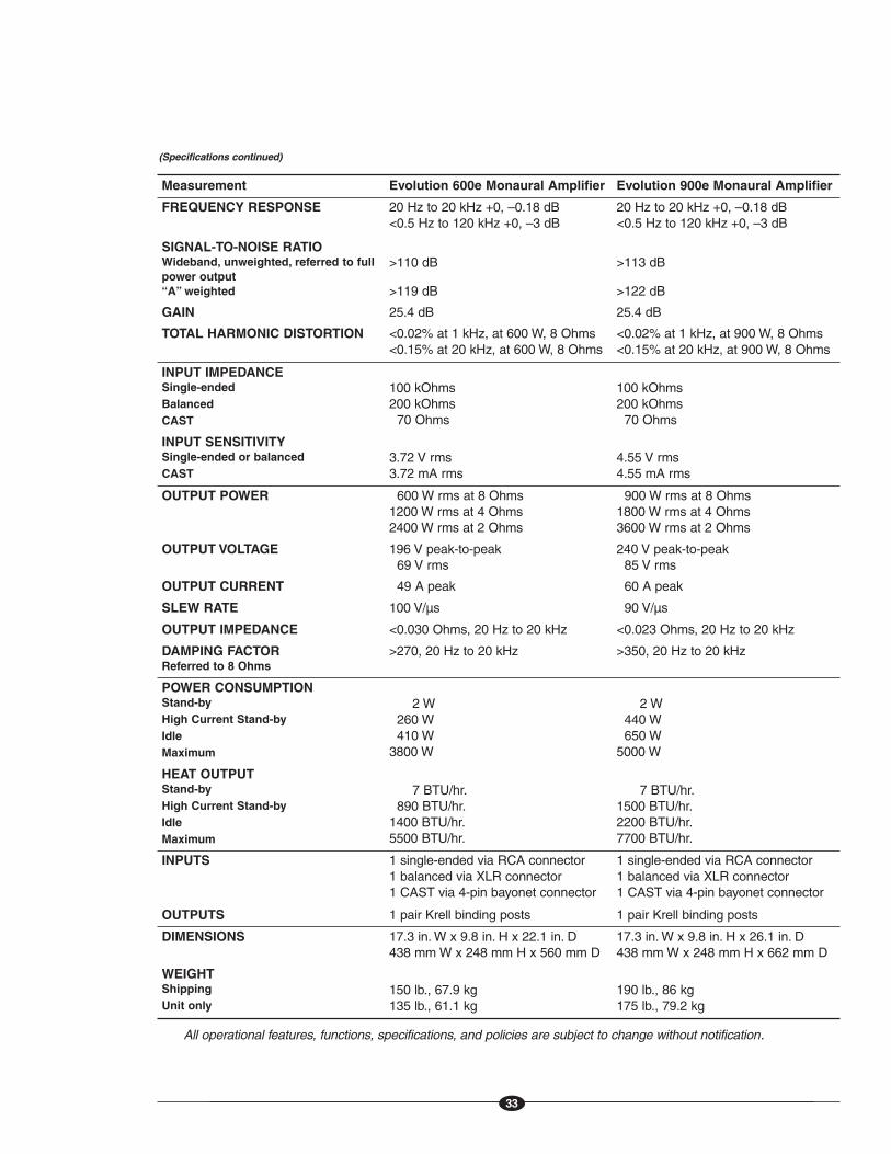
(Specifications continued)
Measurement Evolution 600e Monaural Amplifier Evolution 900e Monaural Amplifier
FREQUENCY RESPONSE 20 Hz to 20 kHz +0, –0.18 dB <0.5 Hz to 120 kHz +0, –3 dB
20 Hz to 20 kHz +0, –0.18 dB <0.5 Hz to 120 kHz +0, –3 dB
SIGNAL-TO-NOISE RATIOWideband, unweighted, referred to fullpower output“A” weighted
>110 dB
>119 dB
>113 dB
>122 dB
GAIN 25.4 dB 25.4 dB
TOTAL HARMONIC DISTORTION <0.02% at 1 kHz, at 600 W, 8 Ohms <0.15% at 20 kHz, at 600 W, 8 Ohms
<0.02% at 1 kHz, at 900 W, 8 Ohms <0.15% at 20 kHz, at 900 W, 8 Ohms
INPUT IMPEDANCESingle-endedBalancedCAST
100 kOhms 200 kOhms
70 Ohms
100 kOhms 200 kOhms
70 Ohms
INPUT SENSITIVITYSingle-ended or balanced CAST
3.72 V rms3.72 mA rms
4.55 V rms4.55 mA rms
OUTPUT POWER 600 W rms at 8 Ohms 1200 W rms at 4 Ohms2400 W rms at 2 Ohms
900 W rms at 8 Ohms 1800 W rms at 4 Ohms3600 W rms at 2 Ohms
OUTPUT VOLTAGE 196 V peak-to-peak 69 V rms
240 V peak-to-peak 85 V rms
OUTPUT CURRENT 49 A peak 60 A peak
SLEW RATE 100 V/µs 90 V/µs
OUTPUT IMPEDANCE <0.030 Ohms, 20 Hz to 20 kHz <0.023 Ohms, 20 Hz to 20 kHz
DAMPING FACTORReferred to 8 Ohms
>270, 20 Hz to 20 kHz >350, 20 Hz to 20 kHz
POWER CONSUMPTIONStand-byHigh Current Stand-byIdleMaximum
2 W260 W 410 W
3800 W
2 W440 W 650 W
5000 W
HEAT OUTPUTStand-byHigh Current Stand-byIdleMaximum
7 BTU/hr.890 BTU/hr.
1400 BTU/hr.5500 BTU/hr.
7 BTU/hr.1500 BTU/hr.2200 BTU/hr.7700 BTU/hr.
INPUTS 1 single-ended via RCA connector 1 balanced via XLR connector 1 CAST via 4-pin bayonet connector
1 single-ended via RCA connector 1 balanced via XLR connector 1 CAST via 4-pin bayonet connector
OUTPUTS 1 pair Krell binding posts 1 pair Krell binding posts
DIMENSIONS 17.3 in. W x 9.8 in. H x 22.1 in. D 438 mm W x 248 mm H x 560 mm D
17.3 in. W x 9.8 in. H x 26.1 in. D 438 mm W x 248 mm H x 662 mm D
WEIGHTShippingUnit only
150 lb., 67.9 kg135 lb., 61.1 kg
190 lb., 86 kg175 lb., 79.2 kg
All operational features, functions, specifications, and policies are subject to change without notification.

OWNER’S REFERENCE
V01.0
KRELL INDUSTRIES, LLC
45 CONNAIR ROAD
ORANGE, CT 06477-3650 USA
TELL: 203-298-4000 • FAX: 203-891-2028
E-MAIL: sa les@kre l lon l ine.com
ht tp : / /www.kre l lon l ine.com
EVOLUTION e SERIES AMPLIFIERS
302e AND 402e STEREO
403e THREE-CHANNEL
600e AND 900e MONAURAL