Embed Size (px)
Citation preview

Instructions for Use
Owner’s Reference
THE LEADER IN AUDIO ENGINEERING
Showcase 7Showcase 6Showcase 5
Multichannel Amplifier
© 2002 by Krell Industries, Inc. All rights reserved P/N 306039
This product is manufactured in the United States of America. Krell® is a registered trademark of KrellIndustries, Inc., and is restricted for use by Krell Industries, Inc., its subsidiaries, and authorized agents. KrellCurrent Mode™ is a trademark of Krell Industries, Inc. All other trademarks and tradenames are registeredto their respective companies.
Showcase 7Showcase 6Showcase 5Multichannel Amplifier
Instructions for Use
v 02.1
Krell Industries, Inc.45 Connair RoadOrange, CT 06477-3650 USA
TEL 203-799-9954FAX 203-891-2028E-MAIL [email protected] http://www.krellonline.com
This product complies with the EMC directive (89/336/EEC) and the low-voltagedirective (73/23/EEC).
The amplifier must be placed on a firm, level surface where it is not exposed todripping or splashing.
The ventilation grids on the top, bottom, and sides of the amplifier must be unob-structed at all times during operation. Do not place flammable material above orbeneath the amplifier.
Contact your authorized Krell dealer, distributor, or Krell before using any devicesdesigned to alter or stabilize the AC power for the Showcase Amplifier.
Before connecting the Showcase Amplifier, make sure the amplifier is turned offand any output device (such as a preamplifier) is in mute or stand-by mode. Makesure all cable terminations are of the highest quality and free from frayed ends,short circuits, or cold solder joints.
Use only one input to each amplifier channel at a time.
If the red LED flashes when the amplifier is in the stand-by mode, unplug theamplifier to reset the protection circuit. Check the loudspeakers and loudspeakercables for potential short circuits before reconnecting the amplifier to your system.
THERE ARE NO USER SERVICEABLE PARTS INSIDE THE PREAMPLIFIER
Please contact your authorized Krell dealer, distributor, or Krell if you have any ques-tions not addressed in this reference manual.
CONTACTINFORMATION
WARNINGS
Contents
Krell Showcase Amplifier iii
INTRODUCTION 1
DEFINITION OF TERMS 2
UNPACKING 3
PLACEMENT 4AC Power Guidelines 4
FRONT PANEL DESCRIPTION 6
BACK PANEL DESCRIPTION 8
CONNECTING THE SHOWCASE AMPLIFIER TO YOUR SYSTEM 10
Input and Output Connections 10
AMPLIFIER OPERATION 12On/Off and Operation 12
TROUBLESHOOTING SYSTEM NOISE 13
QUESTIONS AND ANSWERS 14
WARRANTY 15
RETURN AUTHORIZATION PROCEDURE 16
SPECIFICATIONS 17
Page
iv Krell Showcase Amplifier
FIGURE 1 The Showcase Amplifier Front Panel 5
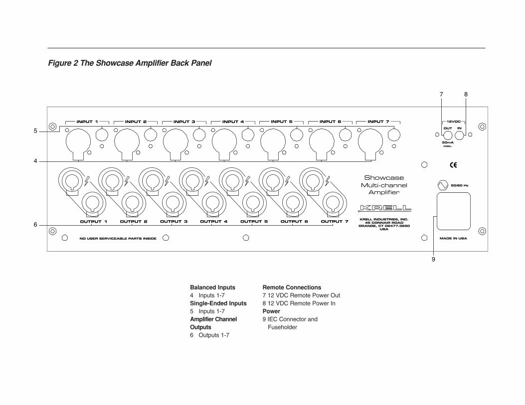
FIGURE 2 The Showcase Amplifier Back Panel 7
Illustrations
Page
Krell Showcase Amplifier 1
Thank you for your purchase of a Krell Showcase Amplifier.
The Showcase Amplifier is a flexible design that delivers five, six, or seven channels of amplification. All three configurations includeinput and output connections for all seven channels. The amplifiersdiffer only by how many channels are housed within the amplifier. A Showcase 5 includes five amplifier channels, a Showcase 6includes six amplifier channels, and a Showcase 7 includes sevenamplifier channels. The Showcase 5 and Showcase 6 may beupgraded with additional channels, up to seven. The ShowcaseAmplifier has balanced and single-ended inputs for compatibilitywith other components. The amplifiers can be operated using the12 VDC power on/off (12 V trigger) signals from other components.The Showcase Amplifier is versatile, fitting a variety of installationsincluding rack-mounted and inside cabinetry.
Please contact your Krell-authorized dealer or distributor for infor-mation on upgrading your amplifier to six or seven channels.
This reference manual contains important information on place-ment, installation, and operation of the Showcase Amplifier. Pleaseread this information carefully. A thorough understanding of thesedetails helps ensure satisfactory operation and long life for yourShowcase Amplifier and related system components.
Introduction
2 Krell Showcase Amplifier
Following are the definitions of key terms used in your owner’s ref-erence manual.
BalancedA symmetrical input or output circuit that has equal impedance fromboth input terminals to a common ground reference point. Theindustry standard for professional and sound recording installations,balanced connections have 6 dB more gain than single-ended con-nections and allow the use of long interconnect cables. Balancedconnections are less susceptible than single-ended connections toinduced noise from the system or the environment.
Single-endedA two-wire input or output circuit. Use care when using single-ended connections as the ground connection is made last and bro-ken first. Turn the system off prior to making or breaking single-ended connections. Single-ended connections are not recommend-ed for connections requiring long cable runs.
OffWhen the AC power cord is not plugged into the wall, the redstand-by LED is not illuminated and the component is off.
Stand-by ModeWhen the AC power cord is plugged into the wall, the red stand-byLED illuminates, indicating that the component is in the stand-bymode. This low power consumption status keeps the audio and cir-cuits at idle. Krell recommends leaving the component in the stand-by mode when it is not playing music.
Operational ModeFrom the stand-by mode, when the power button on the front panelis pressed and the blue power LED illuminates, the component is inthe operational mode and ready to play music.
Krell Current ModeA proprietary Krell circuit topology in which the audio gain stages ofa component operate in the current rather than the voltage domain.This unique technology provides the component with exceptionalspeed and a wide bandwidth.
Definition of Terms
INPUT AND OUTPUTCONNECTIONS
OPERATION
TECHNOLOGY
Unpacking
Krell Showcase Amplifier 3
1. Open the shipping box, and remove the top layer of foam. Thefollowing items are visible:
1 Showcase Amplifier
1 Accessory Kit containing:
1 AC power cord1 12 VDC output (12 V trigger) cable1 spare AC mains fuse1 10 A slow-blow fuse for 100–120 VAC1 5 A slow-blow fuse for 220–240 VAC
1 packet containing the owner’s reference manual and thewarranty registration card.
Two people are needed to remove the amplifier from the shippingbox.
2. Grasp the underside of the amplifier and lift it straight out of the shipping box.
3. Place the amplifier in a safe location and remove the protectiveplastic wrapping.
If any of these items are not included in the shipping box, please contactyour authorized Krell dealer, distributor, or Krell for assistance.
Save all packing materials. If you ship your amplifier in the future, repackthe unit in its original packaging to prevent transit damage. See ReturnAuthorization Procedure, on page 16, for more information.
IMPORTANT
Notes
4 Krell Showcase Amplifier
Before you integrate the Showcase Amplifier into your system,review the following guidelines to choose the location for the com-ponent. This will facilitate a clean, trouble-free installation.
The Showcase Amplifier requires at least two inches (5 cm) ofclearance on each side and at least two inches (5 cm) of clearanceabove and below the component to provide adequate ventilation.
The Showcase Amplifier does not require any type of special rackor cabinet for installation. For the dimensions of your amplifier seeSpecifications, on page 17.
Place the amplifier as close to the loudspeakers as possible andkeep the loudspeaker cable length to a minimum. Loudspeakercable adds impedance to the load the amplifier must drive, regard-less of the cable’s gauge. Krell amplifiers drive the lowest imped-ances with ease, but long loudspeaker cables reduce the maximumpower that is delivered to the loudspeakers.
Placement
Krell recommends operating the Showcase Amplifier from a dedi-cated 15-amp AC power line. Please contact your Krell dealer, dis-tributor, or Krell before using any devices designed to alter or stabi-lize the AC power for the Showcase Amplifier.
AC POWER GUIDELINES
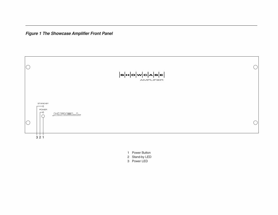
1 Power Button2 Stand-by LED3 Power LED
S H O W C A S E
AMPLIFIER
2 13
STAND-BY
POWER
Figure 1 The Showcase Amplifier Front Panel
The Showcase Amplifier front panel provides power on and indi-cates operating status.
1 Power ButtonUse this button to switch the Showcase Amplifier power betweenthe stand-by and the operational modes and also to switch the 12VDC output (12 V trigger) on and off.
2 Stand-by LEDThe red stand-by LED illuminates when the AC power cord isplugged into the wall. The stand-by LED flashes when the protec-tion circuit is activated.
3 Power LEDThe blue power LED illuminates when the amplifier is in the opera-tional mode.
6 Krell Showcase Amplifier
Front Panel DescriptionSee Figure 1 on page 5
6
4
5
7 8
9
OUTPUT 1 OUTPUT 2 OUTPUT 3 OUTPUT 4 OUTPUT 5 OUTPUT 6 OUTPUT 7
INPUT 1 INPUT 2 INPUT 3 INPUT 4 INPUT 5 INPUT 6 INPUT 7
ShowcaseMulti-channel
Amplifier
KRELL INDUSTRIES, INC.45 CONNAIR ROAD
ORANGE, CT 06477-3650USA
50/60 Hz
MADE IN USA
30mAmax.
OUT IN
12VDC
NO USER SERVICEABLE PARTS INSIDE
Figure 2 The Showcase Amplifier Back Panel
Balanced Inputs4 Inputs 1-7Single-Ended Inputs5 Inputs 1-7Amplifier ChannelOutputs6 Outputs 1-7
Remote Connections7 12 VDC Remote Power Out8 12 VDC Remote Power InPower9 IEC Connector and
Fuseholder
Back Panel DescriptionSee Figure 2 on page 7
8 Krell Showcase Amplifier
The Showcase Amplifier back panel provides connections for allinputs and outputs, remote connection input and output links, andthe AC power supply.
4 Inputs 1-7The Showcase Amplifier has seven channel inputs for outputdevices with balanced XLR connectors.
5 Inputs 1-7The Showcase Amplifier has seven channel inputs for outputdevices with single-ended RCA connectors.
Use only one input to each amplifier channel at a time. You may usethe balanced inputs for some of the amplifier channels and the single-ended inputs for the remaining channels.
6 Outputs 1-7The Showcase Amplifier has seven amplifier channel outputs. Theloudspeaker binding post terminals accept spade lugs, bare wire, orpins. Use the red terminal for the positive connection and the blackterminal for the negative connection.
BALANCED INPUTS
SINGLE-ENDEDINPUTS
AMPLIFIER CHANNELOUTPUTS
BACK PANEL REMOTECONNECTIONS
Tighten loudspeaker binding posts by hand only.
7 12 VDC Remote Power OutThe Showcase Amplifier is equipped with an output that sends 12VDC power on/off (12 V trigger) signals to other Krell componentsand other devices that incorporate a 12 V trigger.
When the component is in the operational mode, the 12 VDC Out pro-vides 12 V of DC output. When the component is in the stand-by mode oroff, the DC output is 0 V.
12 VDC Out (12 V trigger) current is limited to 30 mA.
IMPORTANT
Notes
IMPORTANT
Krell Showcase Amplifier 9
Back Panel Description, continued
8 12 VDC Remote Power InThe Showcase Amplifier is equipped with an input that receives 12VDC power on/off (12 V trigger) signals from other Krell compo-nents and other devices that incorporate a 12 V trigger. This allowsyou to turn the Showcase Amplifier on and off using a Krell or othercomponent in a custom installation.
Consult the owner’s manual of each component used in a custom installa-tion to take full advantage of the Showcase Amplifier remote capability.
9 IEC Connector and FuseholderThe connector is for use with the provided IEC standard 15 amppower cord. The AC mains fuse protects the Showcase Amplifier inthe event of an internal fault.
The AC mains fuse must be replaced with the spare fuse provided. Usethe 10 A slow-blow fuse for 100–120 VAC or the 5 A slow-blow fuse for220–240 VAC.
BACK PANEL REMOTECONNECTIONS, continued
Note
Note
POWER
Connecting the Showcase Amplifier to Your System
10 Krell Showcase Amplifier
The Showcase Amplifier is equipped with balanced and single-ended inputs.
Krell recommends using balanced interconnect cables. Balancedinterconnect cables not only can minimize sonic loss but are alsoimmune to induced noise, especially with installations using longcables. Balanced connections have 6 dB more gain than single-ended connections. When level matching is critical, please keepthis gain value in mind.
The Showcase Amplifier is shipped with shorting pins in the XLRinputs. These pins should remain in the XLR inputs if the amplifieris operating in the single-ended mode. When the shorting pin isinserted, pins 1 (lower left) and 3 (top) are shorted together.Remove the shorting pins to connect the amplifier for balancedoperation.
The XLR pin configuration is described below:
Pin 1 Shield (ground)
Pin 2 Non-inverting (hot) (0°)
Pin 3 Inverting (cold) (180°)
Follow these steps to connect the Showcase Amplifier to your sys-tem.
1. Make sure all power sources and components are off beforeconnecting inputs and outputs.
2. Neatly organize the wiring between the amplifier and all systemcomponents. Separate AC wires from audio cables to preventhum or other unwanted noise from being introduced into thesystem.
3. Connect the interconnect cables from your output device to theamplifier inputs using the balanced (4) or single-ended (5)inputs located on the back panel. The balanced inputs usethree-pin XLR connectors; the single-ended inputs use RCAconnectors. The Showcase 5 uses only inputs 1 through 5 andthe Showcase 6 uses inputs 1 through 6.
Use only one input to each amplifier channel at a time. You may usethe balanced inputs for some of the amplifier channels and the sin-gle-ended inputs for the remaining channels.
INPUT AND OUTPUTCONNECTIONS
IMPORTANT
Connecting the Showcase Amplifier, continued
Krell Showcase Amplifier 11
4. Connect the loudspeaker cables to the Showcase Amplifierchannel output binding posts (6) located on the back panel. The Showcase 5 uses only outputs 1-5 and has caps on thespeaker binding posts for channels 6 and 7. The Showcase 6uses outputs 1-6 and has caps on the speaker binding posts forchannels 6 and 7.
The binding post terminals accept spade lugs, bare wire, or pins.Use the red terminal for the positive connection and the blackterminal for the negative connection.
Tighten loudspeaker binding posts by hand only.
5. Plug the end of the AC power cord into the AC wall outlet.
The amplifier is now ready for operation. See Amplifier Operation,on page 12.
The Showcase 5 and Showcase 6 amplifiers may be upgraded with addi-tional channels, up to seven. Please contact your Krell-authorized dealeror distributor for information on upgrading your amplifier to six or sevenchannels.
IMPORTANT
Note
INPUT AND OUTPUT CONNECTIONS,continued
Amplifier Operation
12 Krell Showcase Amplifier
When powering up your system, turn the amplifiers on last. Whenpowering down your system, turn amplifiers off first. The proce-dures for amplifier operation follow.
1. Plug the end of the AC power cord into the AC wall outlet.
2. The red stand-by LED (2) illuminates.
When the amplifier is first plugged in, there is a brief delay beforeit can be put in the operational mode. Please wait approximately10 seconds.
If the red LED flashes when the amplifier is in the stand-by mode,unplug the amplifier from the AC wall outlet to reset the protectioncircuit. Check the loudspeakers and loudspeaker cables for poten-tial short circuits before plugging the amplifier back into the walloutlet.
3. Press the power button (1) on the front panel. The blue powerLED (3) illuminates and you hear a click. The amplifier is inthe operational mode.
Krell recommends leaving the Showcase Amplifier in the stand-bymode unless you will not be playing music for a long time.
Always turn the amplifier off before changing input connections,and mute or fully attenuate the preamplifier level when switchingsources.
The Showcase Amplifier has tremendous reserves of power andsafely drives loudspeakers to extremely high sound pressure lev-els. However, use care when setting high playback levels and lowerthe volume level at any sign of loudspeaker distress.
ON/OFF AND OPERATION
IMPORTANT
IMPORTANT
Troubleshooting System Noise
Krell Showcase Amplifier 13
When you mix and match high-performance audio components,each with its own ground potential, a low frequency hum may occurin one or all loudspeakers. If this happens when you place theShowcase Amplifier into your system, follow these simple trou-bleshooting steps:
1. Check that all input and output connections are of sound construction.
2. With the amplifier off, remove all the interconnect cables, thenturn the amplifier on. If the hum disappears, turn the amplifieroff and reinsert one of the interconnect cables. Turn the amplifier back on.
3. If the hum reappears with the interconnect cable reinserted, thecable may need to be replaced. Turn the amplifier off and con-nect a different interconnect cable to the same location. Turnthe amplifier back on.
4. If the hum disappears with the interconnect cable reinserted,that cable most likely is sound.
5. Turn the amplifier off, disconnect the interconnect cable, and re-connect one of the other interconnect cables.
6. Repeat steps 3 through 5 until you have checked each inter-connect cable.
7. If all the interconnect cables appear to be sound, and you stillhave hum, you may be experiencing a ground loop. Pleasecontact your authorized Krell dealer, distributor, or Krell for sug-gestions on how to eliminate the hum.
Questions and Answers
14 Krell Showcase Amplifier
Q. Should I turn the Showcase Amplifier off (unplug the amplifier)when not playing music?
A. No. Leave the Showcase Amplifier in the stand-by mode whennot playing music. The stand-by mode avoids cold starts as wellas minimizes heat output and power consumption. Turn theamplifier off if you plan to be away for a period of time, forexample, on vacation. See Amplifier Operation, on page 12.
Q. When I turn the amplifier on there is a loud hum through theloudspeakers. What should I do?
A. When a new component is introduced, a low frequency hummay occur in one or both loudspeakers. Check that all inputand output connections and cables are of sound construction.See Troubleshooting System Noise, on page 13. If the con-nections and cables are sound, you may be experiencing aground loop. This can often be easily eliminated. Please contactyour authorized Krell dealer, distributor, or Krell for suggestions.
Q. When I connect the amplifier to my system using the single-ended inputs, a loud buzz comes from my loudspeakers. Whatis it?
A. Check that the shorting pins for the Showcase Amplifier areinserted into the XLR inputs (the unit is shipped with the pins inplace). When using the single-ended inputs, shorting pins mustbe inserted between pins 1 and 3 to keep external noise fromcorrupting the signal. For more information, see Connectingthe Showcase Amplifier to Your System, on page 10.
Q. I cannot turn the amplifier on. Why not?
A. Make sure the stand-by LED is not flashing. If the stand-by LEDis flashing, unplug the amplifier from the AC wall receptacle andthen plug it back into the AC wall receptacle. If the stand-byLED continues to flash, contact your Krell-authorized dealer ordistributor, or Krell. If no LEDs are illuminated, check the powercord and check the AC mains fuse. To remove the fuse, unplugthe power cord from the amplifier and slide out the fuseholder.
Q. I get no signal from one of the amplifier channels when the unitis on. Why not?
A. Make sure you are not connected to channels 6 or 7 on aShowcase 5, or to channel 7 on a Showcase 6. If you are usingthe single-ended input, make sure the shorting pin is insertedbetween pins 1 and 3, and not between pins 2 and 3.
To register your product for warranty benefits, pleasecomplete and return theWarranty Registration Cardenclosed in the shipping boxwithin 15 days of purchase.Thank you.
This Krell product has a limited warranty of five years for parts and labor on circuitry. Shouldthis product fail to perform at any time during the warranty, Krell will repair it at no cost to theowner, except as set forth in this warranty.
The warranty does not apply to damage caused by acts of God or nature.
The warranty on this page shall be in lieu of any other warranty, expressed or implied, includ-ing, but not limited to, any implied warranty of merchantability or fitness for a particular purpose.There are no warranties which exceed beyond those described in this document. If this productdoes not perform as warranted herein, the owner’s sole remedy shall be repair. In no event willKrell be liable for incidental or consequential damages arising from purchase, use, or inability touse this product, even if Krell has been advised of the possibility of such damages.
Proof of purchase in the form of a bill of sale or receipted invoice substantiating that the unit iswithin the warranty period must be presented to obtain warranty service. The warranty beginson the date of the original retail purchase, as noted on the bill of sale or receipted invoice froman authorized Krell dealer or distributor. Previously owned equipment, when re-purchased froman authorized Krell dealer or distributor, has the balance of the original warranty, based on theoriginal date of manufacture.
The warranty for Krell products is valid only in the country to which they were originally shipped,through the authorized Krell distributor for that country, and at the factory. There may be restric-tions on or changes to Krell’s warranty because of regulations within a specific country. Pleasecheck with your distributor for a complete understanding of the warranty in your country.
If a unit is serviced by a distributor who did not import the unit, there may be a charge for ser-vice, even if the product is within the warranty period.
Freight to the factory is your responsibility. Return freight within the United States (U.S.A.) isincluded in the warranty. If you have purchased your Krell product outside the U.S.A. and wishto have it serviced at the factory, all freight and associated charges to the factory are yourresponsibility.
Krell will pay return freight to the U.S.A.-based freight forwarder of your choice. Freight andother charges to ship the unit from the freight forwarder to you are also your responsibility.
Krell is not responsible for any damage incurred in transit. Krell will file claims for damages asnecessary for units damaged in transit to the factory. You are responsible for filing claims forshipping damages during the return shipment.
Krell does not supply replacement parts and/or products to the owner of the unit. Replacementparts and/or products will be furnished only to the distributor performing service on this unit onan exchange basis only; any parts and/or products returned to Krell for exchange become theproperty of Krell.
No expressed or implied warranty is made for any Krell product damaged by accident, abuse,misuse, natural or personal disaster, or unauthorized modification.
Any unauthorized voltage conversion, disassembly, component replacement, perfora-tion of chassis, updates, or modifications performed to the unit will void the warranty.
The operating voltage of this unit is determined by the factory and can only be changed by anauthorized Krell distributor or at the factory. The voltage for this product in the U.S.A. cannot bechanged until six months from the original purchase date.
In the event that Krell receives a product for warranty service that has been modified in anyway without Krell authorization, all warranties on that product will be void. The product will bereturned to original factory layout specifications at the owner’s expense before it is repaired. Allrepairs required after the product has been returned to original factory specifications will becharged to the customer, at current parts and labor rates.
All operational features, functions, and specifications and policies are subject to change withoutnotification.
Warranty
Krell Showcase Amplifier 15
16 Krell Showcase Amplifier
Return Authorization Procedure
If you believe there is a problem with your component, please con-tact your dealer, distributor, or the Krell factory to discuss the problembefore you return the component for repair. To expedite service, youmay wish to complete and e-mail the Service Request Form in theService section of our website at:
http://www.krellonline.com
To return a product to Krell, please follow this procedure so that wemay serve you better:
1. Obtain a Return Authorization Number (R/A number) and ship-ping address from the Krell Service Department.
2. Insure and accept all liability for loss or damage to the productduring shipment to the Krell factory and ensure all freight (ship-ping) charges are prepaid.
The product may also be hand delivered if arrangements with theService Department have been made in advance. Proof of purchasewill be required for warranty validation at the time of hand delivery.
Use the original packaging to ensure the safe transit of the product tothe factory, dealer, or distributor. Krell may, at its discretion, return aproduct in new packaging and bill the owner for such packaging if theproduct received by Krell was boxed in nonstandard packaging or ifthe original packaging was so damaged that it was unuseable. If Krelldetermines that new packaging is required, the owner will be notifiedbefore the product is returned.
HOW TO RETURNA PRODUCT
IMPORTANT
To purchase additional packaging, please contact your authorizedKrell dealer, distributor, or the Krell Service Department for assis-tance.
HOW TO PURCHASEADDITIONAL PACKING
To contact the Krell Service Department:
TEL 203-799-9954Monday-Friday, 9:00 am to 5:00 pm EST
FAX 203-799-9796E-MAIL [email protected] http://www.krellonline.com
Your Showcase Amplifier product serial number is:SERIAL NUMBER
HOW TO EXPEDITESERVICE
Krell Showcase Amplifier 17
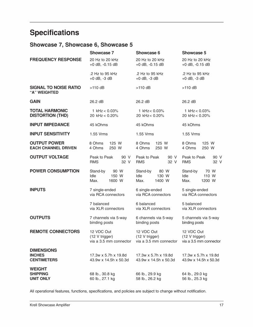
Specifications
Showcase 7, Showcase 6, Showcase 5Showcase 7 Showcase 6 Showcase 5
FREQUENCY RESPONSE 20 Hz to 20 kHz 20 Hz to 20 kHz 20 Hz to 20 kHz+0 dB, -0.15 dB +0 dB, -0.15 dB +0 dB, -0.15 dB
.2 Hz to 95 kHz .2 Hz to 95 kHz .2 Hz to 95 kHz+0 dB, -3 dB +0 dB, -3 dB +0 dB, -3 dB
SIGNAL TO NOISE RATIO >110 dB >110 dB >110 dB“A” WEIGHTED
GAIN 26.2 dB 26.2 dB 26.2 dB
TOTAL HARMONIC 1 kHz < 0.03% 1 kHz< 0.03% 1 kHz < 0.03%DISTORTION (THD) 20 kHz < 0.20% 20 kHz< 0.20% 20 kHz < 0.20%
INPUT IMPEDANCE 45 kOhms 45 kOhms 45 kOhms
INPUT SENSITIVITY 1.55 Vrms 1.55 Vrms 1.55 Vrms
OUTPUT POWER 8 Ohms 125 W 8 Ohms 125 W 8 Ohms 125 WEACH CHANNEL DRIVEN 4 Ohms 250 W 4 Ohms 250 W 4 Ohms 250 W
OUTPUT VOLTAGE Peak to Peak 90 V Peak to Peak 90 V Peak to Peak 90 VRMS 32 V RMS 32 V RMS 32 V
POWER CONSUMPTION Stand-by 90 W Stand-by 80 W Stand-by 70 WIdle 150 W Idle 130 W Idle 110 WMax. 1600 W Max. 1400 W Max. 1200 W
INPUTS 7 single-ended 6 single-ended 5 single-endedvia RCA connectors via RCA connectors via RCA connectors
7 balanced 6 balanced 5 balancedvia XLR connectors via XLR connectors via XLR connectors
OUTPUTS 7 channels via 5-way 6 channels via 5-way 5 channels via 5-waybinding posts binding posts binding posts
REMOTE CONNECTORS 12 VDC Out 12 VDC Out 12 VDC Out(12 V trigger) (12 V trigger) (12 V trigger)via a 3.5 mm connector via a 3.5 mm connector via a 3.5 mm connector
DIMENSIONSINCHES 17.3w x 5.7h x 19.8d 17.3w x 5.7h x 19.8d 17.3w x 5.7h x 19.8dCENTIMETERS 43.9w x 14.5h x 50.3d 43.9w x 14.5h x 50.3d 43.9w x 14.5h x 50.3d
WEIGHTSHIPPING 68 lb., 30.8 kg 66 lb., 29.9 kg 64 lb., 29.0 kgUNIT ONLY 60 lb., 27.1 kg 58 lb., 26.2 kg 56 lb., 25.3 kg
All operational features, functions, specifications, and policies are subject to change without notification.
Krell Industries, Inc.45 Connair RoadOrange, CT 06477-3650 USA
TEL 203-799-9954FAX 203-891-2028E-MAIL [email protected] http://www.krellonline.com
Showcase 7Showcase 6Showcase 5
Multichannel Amplifier
v 02.1