Embed Size (px)
Citation preview
0 MIL-W-4613211 March 1970
MILITARY SPECIFICATION
WELDING , FUSION, ELECTRON BEAM, PROCESS FOR
This specification is mandatory for use by all Departmentsand Agencies of tha Department of Defanse.
1. SCOPE
1.1 m. This specification covers the requirements for the electronbeam fusion walding procass.
2. APPLICABLE DOCUNENTS
2.1 The following documents of the issue in effect on the data ofInvitation for bida or request for proposal, form a part of this specificationto the extent specified herein:
SPECIFICATIONS
● MILITARY
MIL-I-6866 - Inspection, Penetrant, Method ofMIL-I-6868 - Inspection Process, Magnetic Particle
STANDARDS
MILITARY
MIL-STD-453 - InapectiOn, Radiographic
(Copies of specifications, standards, drawings, and publications required bysuppliers in connection with specific procurement functions should be obtainedfrom the procuring activity or as directed by the contracting officer. )
2.2 Other publications. The following documents form a part of this.Bpecification to the extent specified herein. Unless otherwise indicated, the
issue in effect on date of invitation for bids or request for proposal shallapply .
AREA-THJM
Downloaded from http://www.everyspec.com
MIL-W-46132
Am3RIcAN SOCIETY FOR TESTING AND MATERIALS (ASTM) STANDARDS
E 8 - Tension Testing of Metallic Materials
(Application fnr copies shouldTesting and Materials, 1916 Race
NATIONAL BUREAU OF STANDARDS
Handbnok 60 X-Ray Protection
(Application fnr copies shouldWashington, D.C. , 20234) .
3. REQUIREMENTS
be addressed to the American Society forStreet, Philadelphia, Pennsylvania 19103.)
be addressed to National Bureau nf Standards,
3.1 Equipment. The welding equipment shall be qualified in accordance with
4.1.
3.2 Operator certification. Electron beam welding equipment productionoperators shall be certified in accordance with 4.2.
3.3 Materials. Materials to be welded shall be in accordance with thematerial and heat-treatment requirements specified on the applicableengineering drawing. ‘
3.4 Weld schedule. A welding schedule shall be established for eachspecific part to be welded (see page 31).
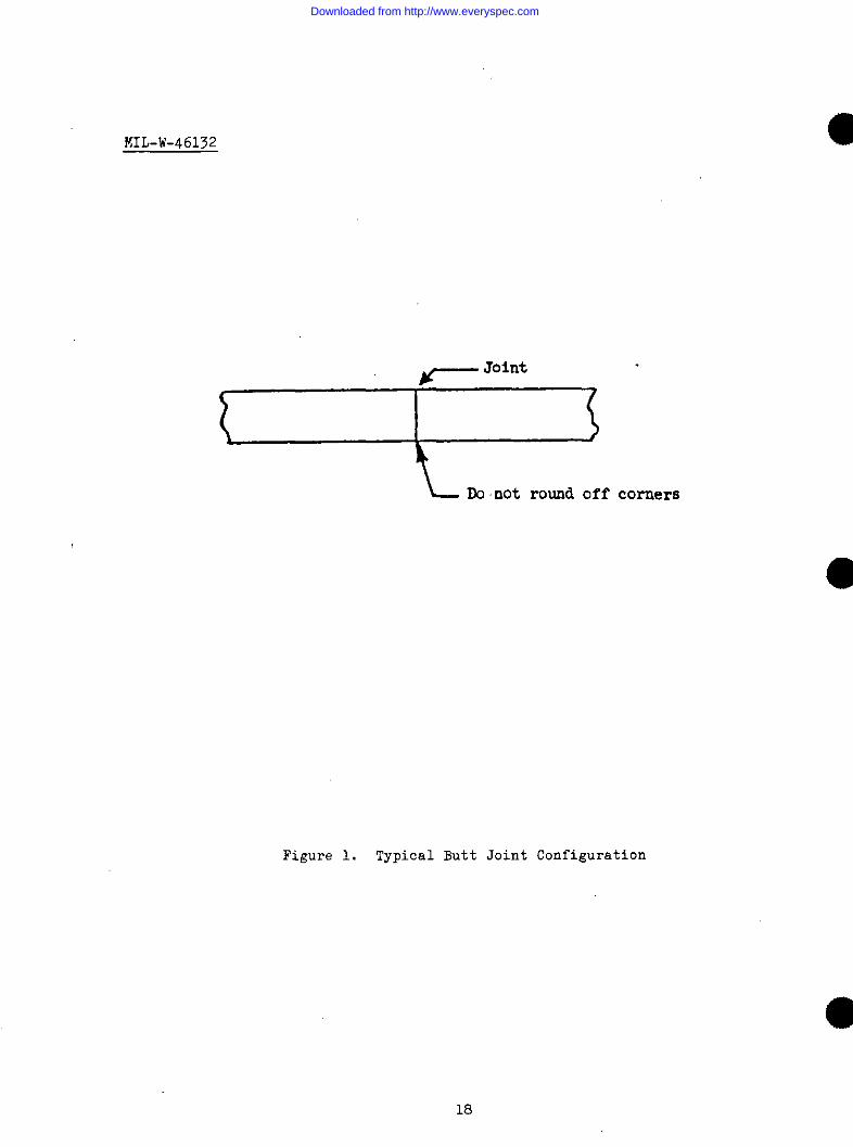
3.5 Weld joint design and dimensional tolerances. Weld jnint design shallbe such that all jnint corners are square and sharp (see figure 1).
3.5.1 Dimensional fit-up tolerances shall be as follnws:
Material thickness range Maximum separation
.020 inch and under Metal to metal contactrequired at all weldlncatinns
.021 inch to .065 inch .002 inch or less
.066 inch to .125 inch .Dj inch or less
.126 inch and above .004 inch nr less
o
3.6 Workmanship. Welded joints shall be examined as gpecified in 5.3 forconformance to the.following requirements:
Downloaded from http://www.everyspec.com
MIL-W-46132
3.6.1 Appearance. Welded joints shall be suitable for the intended use andshell be free of cracks and metallic discontinuities.
3.6.2 Smoothness and contour. Weld beads shall be within the requiredtolerances and shall be free of excessive undercut, and spatter (see 3.6.3).
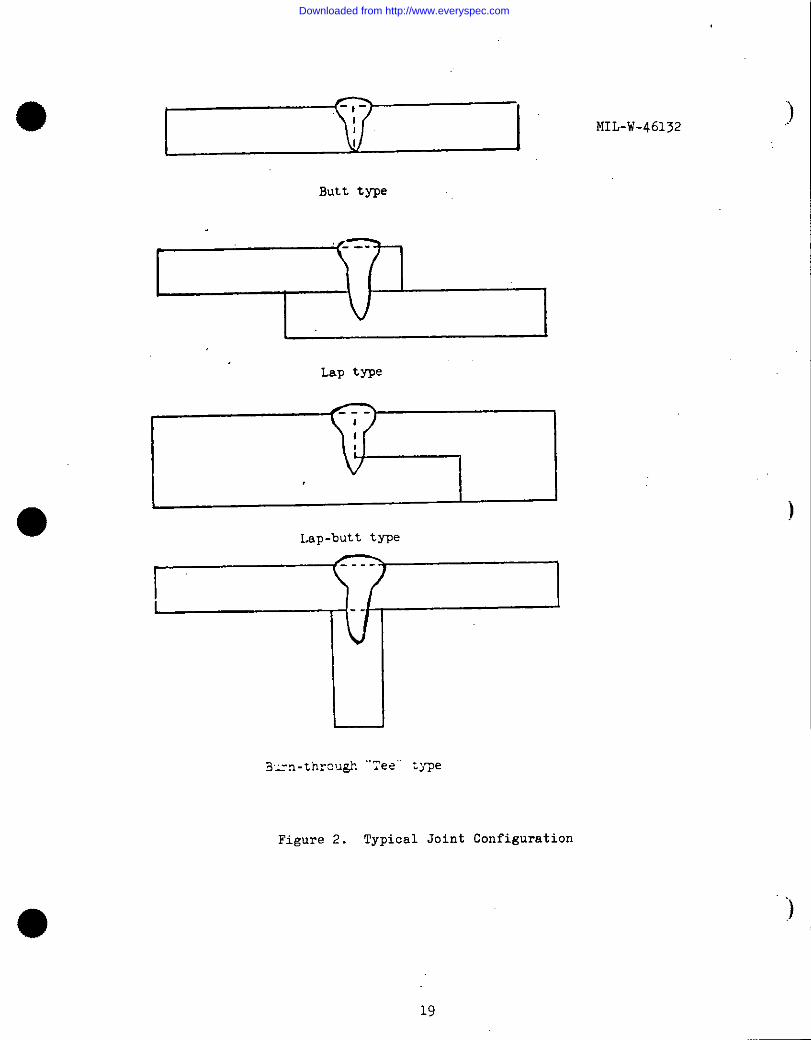
3.6.3 Penetration, buildup, and ❑elt-through for butt, lap, and lap-butt
J@!&?. Unless 0therW18e specified by the applicable engineering drawing, all
welds shall exhibit 100 percent penetration. Buildup and melt-through shall
exceed the parent material thickness. Undercut shall not axceed 10 percent ofthe parent material thickness or 0.003 inch whichever is greater. Cosmeticpaaaes may be used to smooth, blend, and increase build up and drop through(ace figure 2).
3.6.4 Penetration for burn-through type “Tee” joints. Unless otherwisespecified by the applicable engineering drawing, all welds shall “penetrate theleg of a “Tee” joint at least equal to the thickness of the thinner member(see figure 2).
3.6.5 Metallurgically sectioned samples. Sectioned samples shall exhibitno cracka when examined at 20 X magnification. Weld penetration andmetallurgical quality sh~llorder.
3.6.6 Weld bead widths.following limits:
Depth of weld
meet the requirements
The width of the weld
Weld
shown in the contract or
bead shall not exceed the
surface width
.010 inch to .125 inch 1 x depth
.125 inch to .250 inch l/2 x depthGreater than .250 inch 1/3 x dapth
4. PROCEDURE
4.1 Equipment qualification. Electron beam welding equipment shall bequalified by the welding activity designated in the contract or order andquality control as follows:
4.1.1 Vacuum chamber pumping equipment and control system. The vacuum
pumping system shall be considered acceptable if the system is capable ofgenerating a working vacuum of 10-4 Torr within fifteen (15) minutes afterthe start of the pumping system.
4.1.2 Voltage meter and current meter shall be calibrated at 90 day
intervals.
Downloaded from http://www.everyspec.com
MIL-W-46132
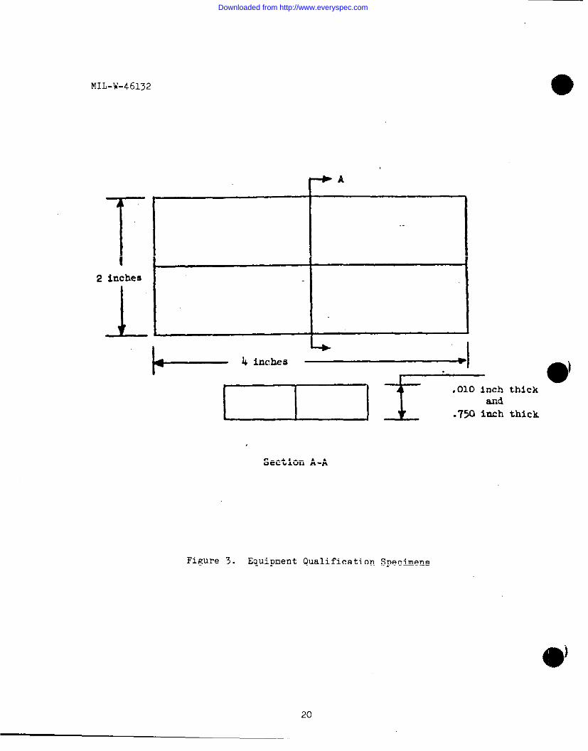
4.1.3 Electron gun, electrical power supply and control system. Thegeneral operating capability of the electron optics, welding parameterinatrwnentation, and work manipulating equipment shall be established throughthe verification of welding results. Welding shall be performed on testblocks of annealed 304 stainless steel conforming to Figure 3, or by continualsurveillance of quality control samples.
4.1.3.1 Preparation of test blocks for welding. Surfaces of the testblocke to be welded shall be free from objectionable films such as oxides,scale, ink, grease, oil or other foreign material detrimental to the weldingprocess.
4.1.3.2thicknessfollowing
Welding sequence.shown in Figure 3,order for all test
(a) One test weld shallpass.
A series of two (2) butt welds, of each
four (4) inches in length shall be made in thewelds:
be made using appropriate schedule and a single
(b) All electrical parameter instrumentation, including travel speedcontrole, shall be set back to zero.
(c) The identical welding schedule used in 4.1.3.2 (a) shall bere-established and the next test weld completed.
4.1.3.3 Test block evaluation. The welded test block shall be sectioned as.
shown in Figure 3.
4.1.3.4 Failure to meet qualification requirements. Failure of anyindividual weld pass to achieve the required penetration in any section shallbe cause for failure of the machine qualification test.
4.1.4 X-RaY radiation ❑onitoring. Check of X-ray radiation leakage shall
be made on all external surfaces of the equipment. During the radiationleakage monitoring procedure, the electron beam welding equipment shall beoperated at 90 percent of maximum power, with the electron beam grosslydefocused.
4.1.4.1 X-R.sy indication. In the event of any indication of X-rayradiation leakage, the area in question shall be rechecked with X-ray film toconfirm radiation leakage.
4.1.4.2 X-Fiay limitations. X-Ray radiation on any surface of the equipmentindicated by the meter and confirmed by the X-ray film shall not exceed the
permissible radiation levels outlined in NBS Handbook 60, X-ray protection.
●
Downloaded from http://www.everyspec.com
●4.1.4.3 Radiation tests failure. Electron beam
conforming to the maximum X-ray radiation limit as
shall be considered as having failed the equipment
MIL-W-461>2
welding equipment, notdefined in NBS Handbooksafety test.
60,
4.2 Operator certification. Electron beam welding equipment production
operators shall be certified by the designated welding activity and qualiitycontrol a8 follows:
4.2.1 Certification test equipment. Certification tests of all electronbeam welding equipment production operatnrs shall be performed on previouslyqualified electron beam welding equipment.
.4.2.2 Certification requirements. Certification of an electron beamwelding equipment production operator shall be dependent upon his ability toact-up the machine, to weld parts and assemblies”in accordance with thefollowing procedures.
4.2.2.1 Column assembly and alignment. Starting with an electrnn beam
welder in which the column is out of alignment and the filamant has beenremoved, the oeprator shall prepare the machine fnr welding.
4.2.2.2 Certification procedure. Certification procedure shall consist of
the operator setting up and welding two (2) consecutive, acceptable specimens
● of each of the configurations confirming to Figures 4, 5, and 6. Material
shall be annealed 304 stainless steel.
4.2.2.3 Preparation of test specimens for welding. Surfacas of the testeneciraens to be welded shall be free from ob.iectionable films such as oxides..=–– —....scale, ink, grease, oil or other foreign material detrimental to the weldingpr0cesf3. Parta shall be wiped clean with
4.2.2.4
thicknessfollowing
Welding sequence. Each series
shown in Figure 4, of all threeorder:
alcohol or acetone prior to welding.
of two (2) specimens, of eachconfigurations shall be made in the
(a) One certification weld shall be made using the appropriate scheduleand
(b) All
(c) There-established and t~e second certification weld completed.
a single pass.
electrical parameter instrumentation shall be returned to zero.
identical welding schedule used in (a) above shall be
4.2.2.5 Certification requirements. Failure nf the operatnr to meet the
requirements specified in 3.6, in any weld pass, shall be cause for hisfailure of the production operator certification test.
5
Downloaded from http://www.everyspec.com
.7
MIL-W-46132
4.3 Establishment of weld schedules. Electron beam welding schedules shallbe as established by the procuring activity for each specific application andfor each machine to be used in production.
4.5.1 Samples. The number of samples required to establish a weldingschedule shall be determined by the procuring activity, and shall be recordedon the welding schedule sheet (see attachment 1). The number of specimens
required ghould reflect previous welding experience with related materials andconfigurations, part application and life requirements. Samples used toestablish a weld schedule do not necessarily have to be actual parts, but maybe simulated joints. If a simulated joint configuration ia used, a sketch,including the dimensions, must be included in the weld schedule sheet (seeattachment 1).
4.3.2 Target location. Beam focusing targets shall be located in such amanner as to isolate the work piece from any target splatter and heatgenerated during column alignment and beam adjustment procedures.
4.3.3 Preheating. Preheating, by defocused beam techniques, shall not bepermitted unless such procedure has been authorized by the procuring activity.
4.3.4 Filler material. The use of filler materials in electron beam weldsshall be permitted when certified filler wire is used.
4.3.5 Repair weldin&. Repair weldiug by electron beam welding shall bepermitted only when authorized by the procuring activity.
4.3.6 Joint efficiency. Electron beam welded joints shall meet therequirements of the applicable engineering drawing and 3.6.
4.3.7 Production welders identification. Each welded production assembly
shall be marked so as to positively identify it with the welding operator whomade the welds. The welder’s identification symbol shall be assigned by theQuality Control Activity. Identification shall remain on the part at leastuntil final inspection and acceptance of the weld.
4.3.7.1 Identification area. Unless otherwise specified by the applicableengineering drawing, the welder’s identification symbol shall be marked in thevicinity of the weld. The marking shall not be injurious to theserviceability of the part.
4.4 Welding of carbon and low alloy steels. Carbon and low alloy steelsshall be welded with the filler materials, when used, as detailed below.
4.4.1 Post-weld thermal treatment. All welded joints, with one or moremembers made from 4130, 4135, 4140, or 4340 steel shall be post-weld thermaltreated. Weldnents used in the annealed condition shall be post-weld process
Downloaded from http://www.everyspec.com
MIL-W-46132
annealed. Weldments made from details previously hardened to obtain highstrength shall be post-weld stress relieved except the holding temperatureshall be 500 below the tempering temperature. Weldments requiring otherthermal treatments shall be processed in accordance with drawingrequirements. T-1 steel shall not be post-weld thermal processed unless sodesignated by the applicable drawing.
4.4.2 Reweld. Weldments which have been thermal treated to obtain anultimate strength above 160,000 psi shall be annealed before discontinuities
are removed for welding.
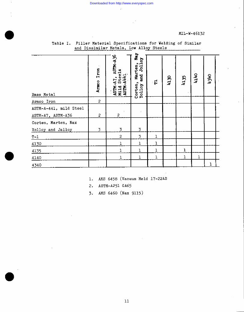
4.4.3 Welding filler materials. Table I shows the appropriate fillermetals to use with the various base metals.
4.5 Welding of stainless and high alloy steels. Stainless and high alloysteels shall be welded with the filler materials, when used, as shown below.
4.5.1 Post-weld thermal treatment. Type 410 stainless steel shall beprocess annealed within twelve (12) hours after welding.
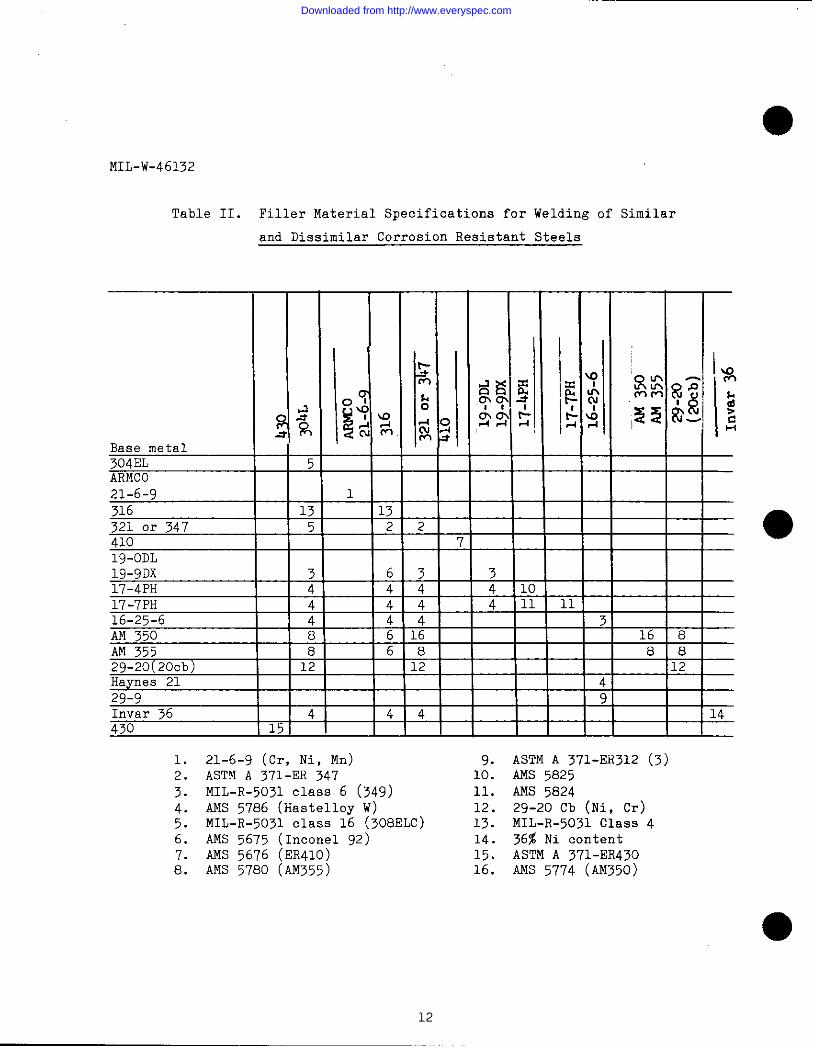
4.5.2 Filler materials. Table II shows the appropriate filler metals touse with the various base metals.
● 4.6 Welding of nickel and cobalt base alloys. Nickel and cobalt-base
alloys shall be welded with the filler materialg, when uged, as shown below.
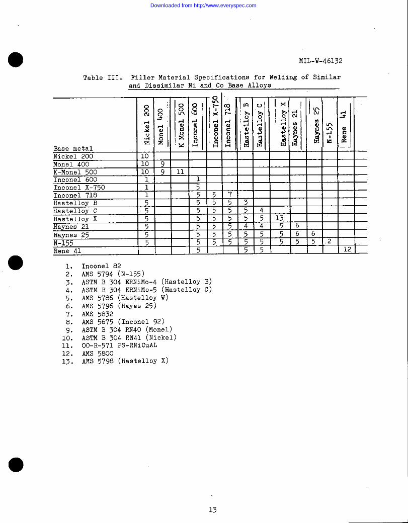
4.6.1 Welding filler materials. Table III shows the appropriate filler
metals to be used with the va?ious base metals.
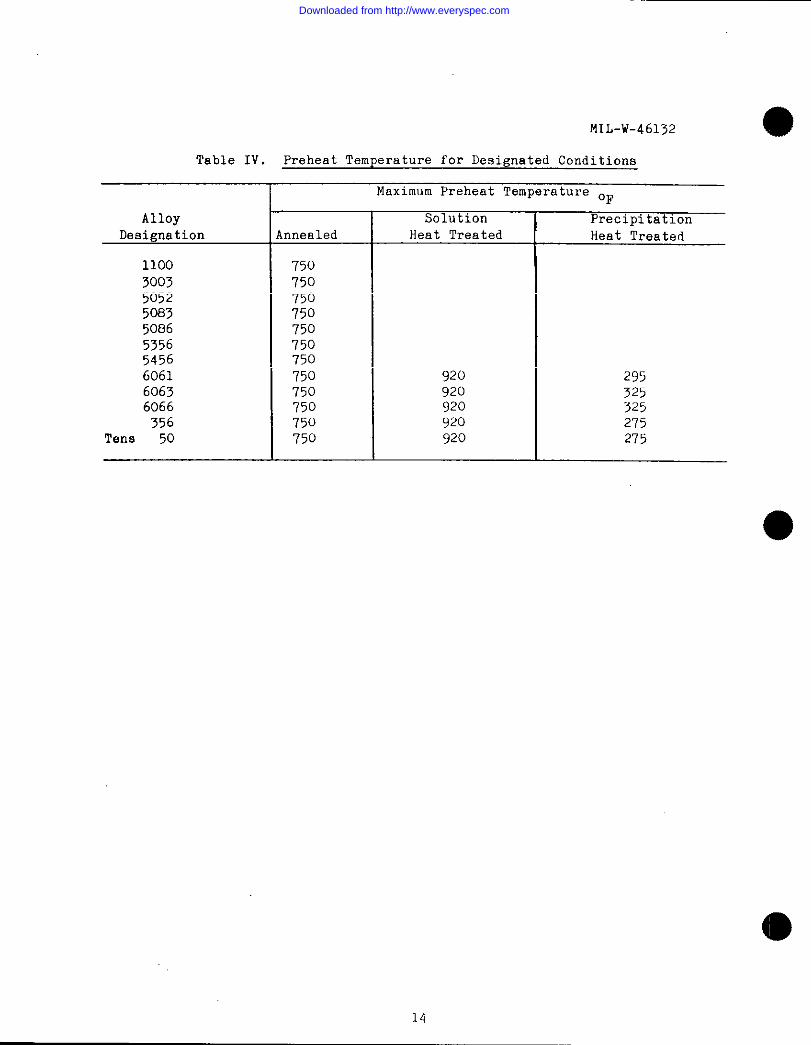
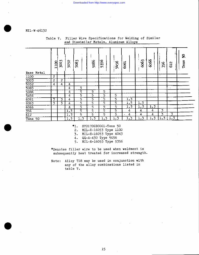
4.7 Welding of aluminum and aluminum alloys. Aluminum and aluminum alloys,after preheating to the applicable maximum temperature shown in table IV,shall be welded with the filler rnater.ials (when used) aS shown in table V.Filler addition is mandatory for welding 6061, 6063, and 6066.
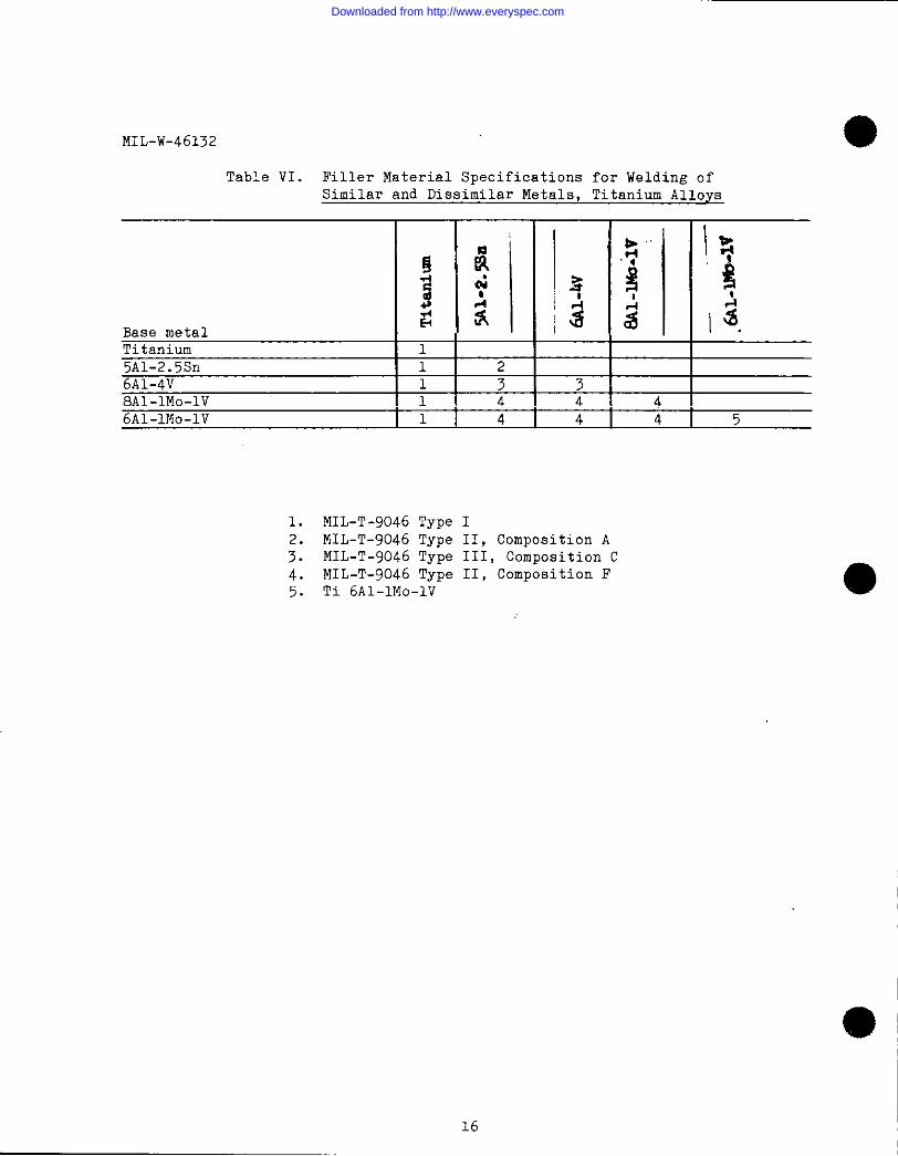
4.8 Welding of titanium and titanium alloys. Titanium and titanium alloys
shall be welded with the filler material, when used, as designated in table VI.
4.9 Welding of refractory metals and alloys. The following refractory
metals and alloys shall be welded only to the metal or alloy of the samedesignation. The filler metal, when used, shall be of the same designation asthe parent metal.
Downloaded from http://www.everyspec.com
MIL-W-46132
Columbium and columbium alloys Tungsten and Tungsten alloys
Columbium C-103 Cb-752 Tungsten W-25ReAS-55 FS-80 D43 Sylvania “A” W-30M0B-66 FS-82 D43C-129y FS-85 SCb-291
Tantalum and Tantalum alloys Molybdenum and molybdenum alloys
Tantalum T-222 Molybdenum TZMT-ill TA-1OW Mo-50Re Mo-O.5Ti
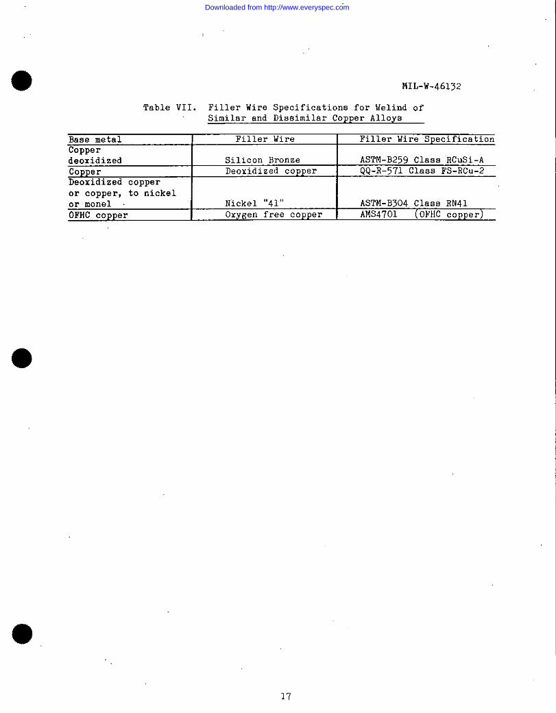
4.10 Welding of copper. Copper shall be welded with the filler materials,when used, as designated in table VII.
5. QUALITY ASSURANCE PROVISIONS
5.1 Equipment qualification. Electron beam welding equipment qualificationshall be maintained by checking weld penetration and quality on sample partswelded with certified schedules. When the sample weldments reproduces theoriginal weld penetration with L 10 percent the welding equipment will retainqualification.
5.1.1 Witnessing of qualification. Quality control shall witness andverify the welding equipment’s compliance to tha requirements of section 4.1 0of this specification.
5.1.2 Sectioning of qualification test blocks. If quality control samples
are not used, the applicable welding ~ctivity shall section the weldedqualification test blocks as shown in figure 7. All qualification welds shallmeet the requirements of section 3.6.
5.2 Operator certification. Production electron beam welding operatorsshall be certified at twelve (12) month intervals or by continual surveillanceof production welding and Q.C . specimens.
5.2.1 Witness of certification. Quality control shall witness and varifythe welding operator’s compliance to the requirement of section 4.2 of thisspecification.
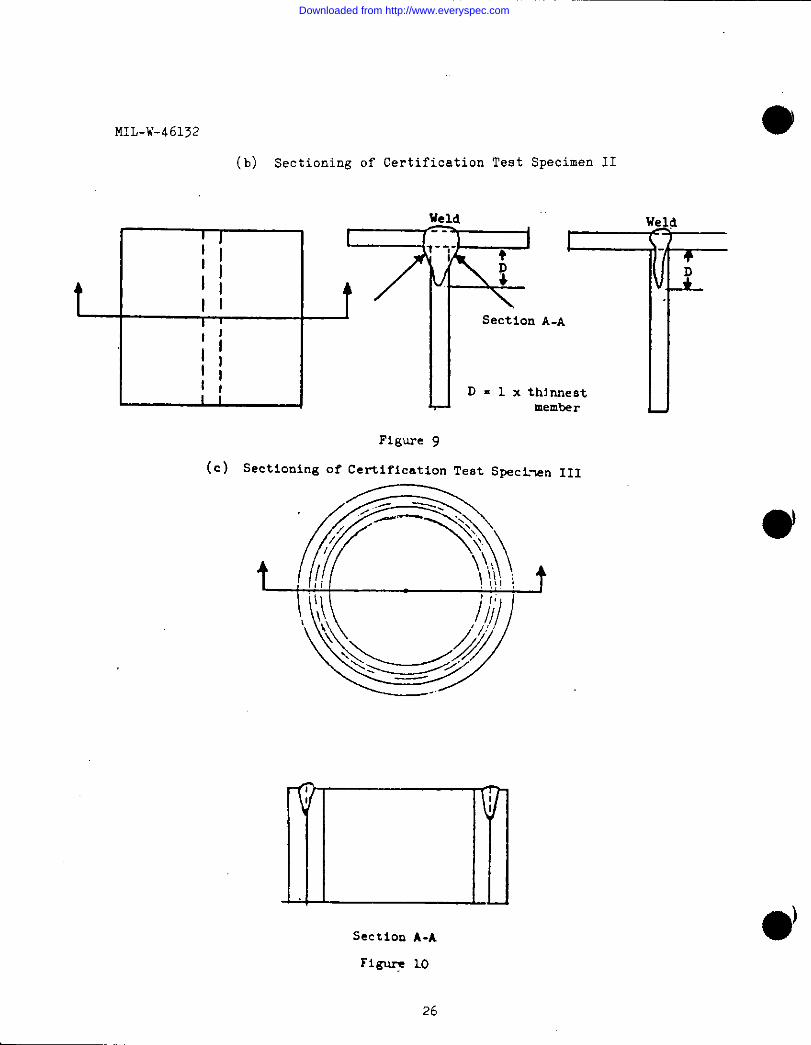
5.2.2 Sectioning of certification test blocks. If there are no Q.C.specimens, the applicable welding activity shall section the weldingcertification test blocks as shown in figures 8, 9, and 10.
Downloaded from http://www.everyspec.com
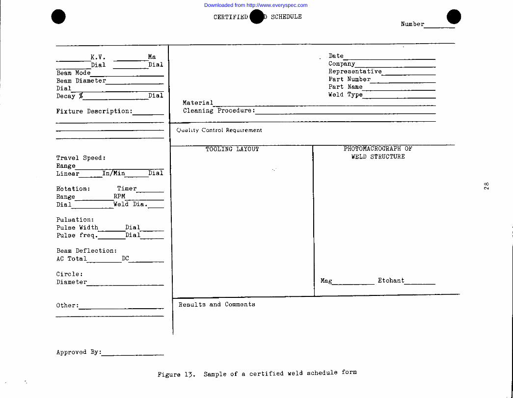
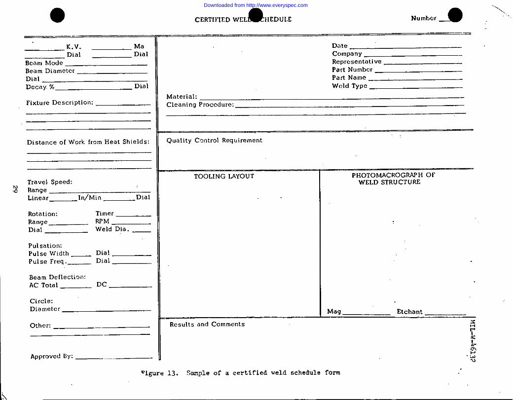
5.3 Weld schedules. Weld schedules shallspecification and the applicable engineeringshall meet the requirements of section 3.6.required for a certified weld schedule. See
MIL-W-46132
satisfy the requirements of thisdrawing. All certification weldsA minimum of two.sainplesareattachment 1 for a suggested
ce~tified weld schedule form. The welds shall be ev.aluetedby:
(a) 20 X inspection of weld surface(b) Mettalographic examination of welded jointm @ 20 X magnification
5.4 Production welder’s identification stamps. Unless otherwise specifiedby the applicable engineering drawing, the following methods of marking areacceptable:
(a) Impression stamping - when required by the contract,(b) Ink marking,(c) Cerdboard or metal tag firmly attached to the part - when required by
the contract.
5.5 Production quality control. Production quality control shall consistof the inspection methods shown below or shall be in accordance with therequirements of the applicable engineering drawing.
5.5.1 Magnetic materials. All magnetic materials shall be degaussed prior
to electron beam welding.
5.5.2 Examination of product. All welds shall be visually examined to
ineure compliance with the requirements of 3.6.1 through 3.6.4. In addition,
the following inspection procedures shall be used as specified in the contractor order.
(a)(b)(c)
5.5.3
Magnetic particle inspection in accordance with MIL-1-6868
Penetrant inspection in accordance with MIL-I-6866Radiographic inspection in accordance with MIL-STD-453 one-halfvalues for porosity.
Tensile strength. When required by the contract or order, tensile
strength tests shall be conducted in accordance with ASTM method E8.
5.5.4 Retests. If the results of the process control tests for aparticular production set-up are not satisfactory, the weld schedule, theparent material, joint configuration, and the welding equipment shall beexamined, and any unsatisfactory conditions corrected.
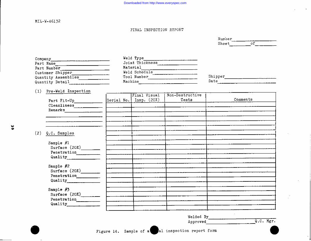
5.5.5 Weld final inspection report shall be used for production control(see attachment 2 for recommended form).
Downloaded from http://www.everyspec.com
MIL-W-46132
6. PREPARATION FOR DELIVRRY
6.1 Packaging. Electron beam welded assemblies shall be packaged forhandling and delivery in accordance with the applicable document (packagingdata sheet or specification) .
7. NOTES
7.1 Definitions.
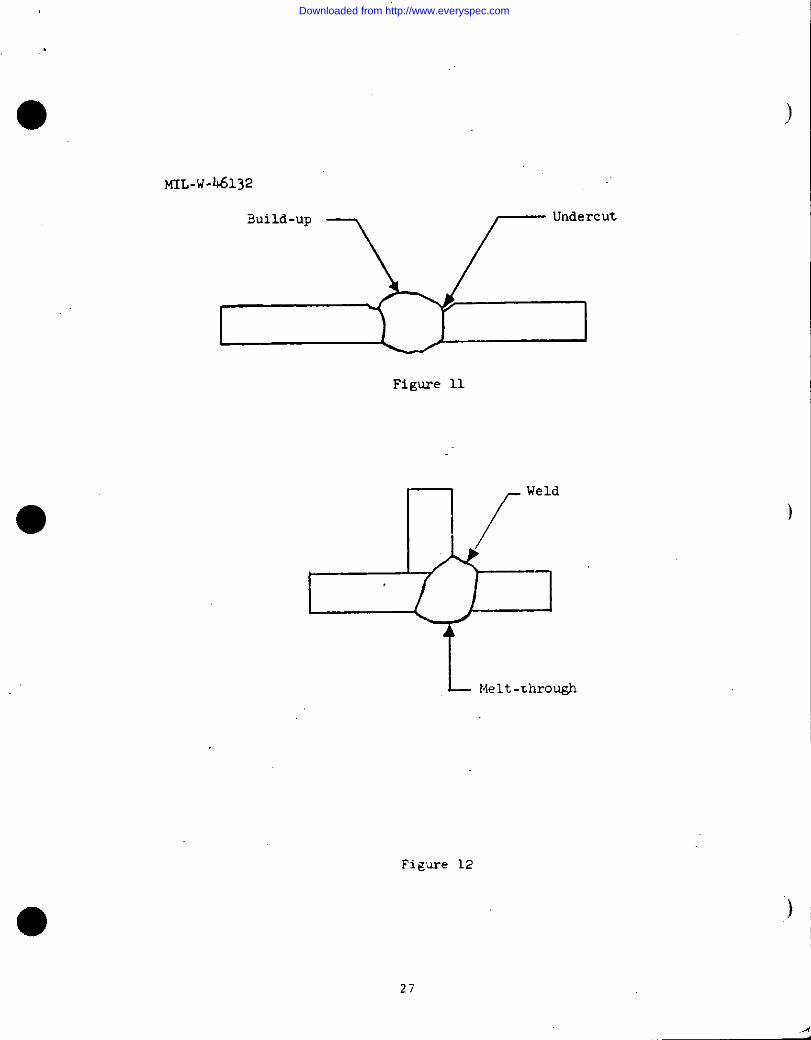
7.1.1 Undercut and buildup. Undercut is evidenced by a reduction of theparent material thickness adjacent to the weld. Buildup is evidenced by anincrease of parent material thickness at the weld (see figure 11).
7.1.2 Melt-through. Melt-through is evidenced by a deposit of weldmaterial on the side opposite that weld (see figure 12) .
Custodian: Preparing activity:
Army - MR Army - MH
Navy - ASAir Force - 11
Review Activities: Project No. THJM-0025
Army - AT, MU,Navy -Air Force -
User activities:
Army - WCNavy - MC. SH, YD
(KBWP# ID-0423A/DIsK O167A. FOR AMMRC USE ONLY)
10
Downloaded from http://www.everyspec.com
4) MIL-W-46132
Table 1. Filler Material Specifications for Welding of Similar
and Dissimilar Metals, Low Alloy Steels
~ h
yi?:
$ 22a alo0b -$$(Lj ~ % so ~$~’; RE
~-~ ‘w s 2
Base Metal!2~~ g$
U*Armco Iron 2
ASTM-A-441, mild Steel
ASTM-A7 , ASTM-A36 2 2
Corten, Marten, Nax
Yolloy and Jalloy 3 3 3
T-1 2 3 1
4130 1 1 1
4135 1 1 1 1
4140 1 1 1 1
4340
1. MIS 6458 (Vacuum Meld 17-22AS
2. ASTM-A251 GA65
3. MS 6460 (liax 9115)
11
Downloaded from http://www.everyspec.com
MIL-W-46132
Table II. Filler Material Specifications for Welding of Similar
and Dissimilar Corrosion Resistant Steels
Base metal
304ELARMCO21-6-9316321 or 34741019-ODL
=
19-9DX 317-4PH 417-7PH 416-25-6 4AM 350 8AM 355 829-20 20cb 12Ha nes 21
29-9Invar 36 4430 15
1.2.
3.4.5.6.
7.8.
1 Irl-!
~: t
ii
c
L 2 ~cd l-m ~
113
2 2
6 34 44 44 46 166 8
12
4 4
21-6-9 (Cr, Ni, Mn)ASTM A 371-ER 347MIL-R-5031 class 6 (349)
AMS 5786 (Hastelloy W)MIL-R-5031 class 16 (308ELc)AMS 5675 (Inconel 92)AMS 5676 (ER41O)AMS 5780 (AM355)
—
-ii
—
F-t- z16 8
8812
14
9.10.11.12.13.14.15.16.
ASTM A 371-Efi312 (3)AMS 5825AMS 582429-20 Cb (Ni, Cr)MIL-R-5031 class 436% Ni contentASTM A 371-ER430AMS 5774 (AM350)
12
Downloaded from http://www.everyspec.com
NIL-W-46132
Table III. Filler Material Specifications for Welding of Similarand Dissimilar Ni and Co Base Alloys
~ ‘.
I
f E: ~ :1 lj : $ “;’ 1; :! ~: ~ ~.-4 w al
2 al c c0
a g $ $‘0
.s 5 !~ ~z x 1; ~ la “ ; g i ? 1
Base metalY l-l \sl Is ~ $ .
Nickel 200 10None1 400 10 9
K-Monel 500 10 9 11Inconel 600 1 1Inconel X-750 1 5Inconel 718 1 5 5 7Hastelloy B 5 5 5 5 3Hastelloy C 5 5 5 5 4Hastelloy X 5 ; 5 5 5 5 13Haynes 21 5 5 5 5 4 4 5 6Haynes 25 5 5 5 5 5 5 5 6 6N-155 5 5 5 5 5 5 5 5 5 .2Rene 41 5 5 5 12
1.2.
3.4.5.6.7.8.
9.10.11.12.13.
Inconel 82AMS 5794 (N-155)ASTMB 304 ERNiMo-4 (Hastelloy B)ASTMB 304 ERNiMo-5 (Hastelloy c)AMS5786 (Hastelloy W)AMS5796 (Hayes 25)AMS5832ANS 5675 (Inconel 92)ASTMB 304 RN40 (Monel )ASTMB 304 RN41 (Nickal)00-R-571 FS-HNiCuALAMS 5800ANS 5798 (Hastelloy X)
13
Downloaded from http://www.everyspec.com
MIL-W-461>2
Table IV. Preheat Temperature for Designated Conditions
AlloyDesignation
110030035052
50035086
53565456606160636066
556Tens 50
Maximum Preheat Temperature ~F
-
nnealed
750750 ~750750750750750750750750750750
SolutionHeat Treated
920920920920920
Precipitation
Heat Treated
295325>25
275275
14
Downloaded from http://www.everyspec.com
● MIL-W-46132
Table V.
Base Metal110030035052508350865456606160636066356612Tens 50
Filler Wire Specifications for Welding of Similarand Dissimilar Metals, Aluminum Alloys
~ g : #
B222444
454545
33453345
41,3 ;1,3 51,3 1,3
I IQ‘~ ~ “~;*
,In
5 55 5 55 5 55 5 55 5 55 5. 55 5 5
1,3 1,3 1,3
I: s
!07
1~ ~, ~ +1 “;I
1,31,3 1,3
4 4 34 4 3 3
1,3 1,3 1,3 1,3
*1 . STO170GBOO01 -Tens 50MIL-E-16053 Type llCO
;: MIL-E-16053 Type 4043
4. QQ-A-430 Type 5056
5. MIL-E-16053 Type 5356
*Denotes filler wire to be used when weldment issubsequently heat treated for increased strength.
Note: Alloy 718 may be used in conJ~ctiOn withany of the alloy combinations listed intable V.
15
Downloaded from http://www.everyspec.com
MIL-W-46132
Table VI. Filler Material SpecificationsSimilar and Dissimilar Metals,
for Welding ofTitanium Alloys
~ I~9 a1! $ : “$’ “$$ 2 ~; g @
Base metalTitanium 15A1-2.5Sn 1 26A1-4V 1 3 38A1-lMO-lV 1 4 4 46A1-lMO-lV 1 4 4 4 5
1. MIL-T-9046 Type I2. MIL-T-9046 Type II, Composition A
3. MIL-T-9046 Type III, Composition C
4. MIL-T-9046 Type II, Composition F5. Ti 6A1-lMO-lV
16
Downloaded from http://www.everyspec.com
MIL-W-46132
Table VII. Filler Wire Specifications for \ielind of
Similar and Dissimilar Copper Alloys
Base metal Filler Wire Filler Wire SpecificationCopperdeoxidized Silicon Bronze ASTM-B259 Class RCuSi-A
Copper Deoxidized copperDeoxidized copper
QQ-R-571 class Fs-Rc”_2
or copper, to nickelor monel Nickel “41” ASTM-B304 class RN41
OFHC copper Oxygen free copper AMS4701 (OFl{Ccopper)
●
17
Downloaded from http://www.everyspec.com
MIL-W-46132
L_ I¬ roundoff corners
Figure 1. Typical Butt Joint Configuration
18
Downloaded from http://www.everyspec.com
1 1“ MIL-W-46132
Butt type
diiiaLap-butt type
[’ 1
3_-n.thra@. “Tee” :j’pe
Figure 2. Typical Joint Configuration
.)
)
19
Downloaded from http://www.everyspec.com
MIL-W-46132
2 Inches
1
SectionA-A
Figure 3. Equipment Qualification Specimens
20
thick
thick
Downloaded from http://www.everyspec.com
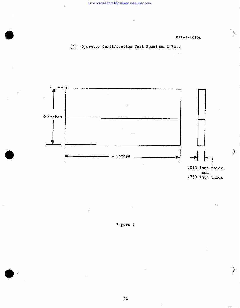
r ‘2 inche6
1
MIL-W-461>2
(A) Operator Certification Test Specimen I Butt
.010 inch thickand
.750 inch thick
Figure 4
.)
“)
)
21
Downloaded from http://www.everyspec.com
MIL-W-46132
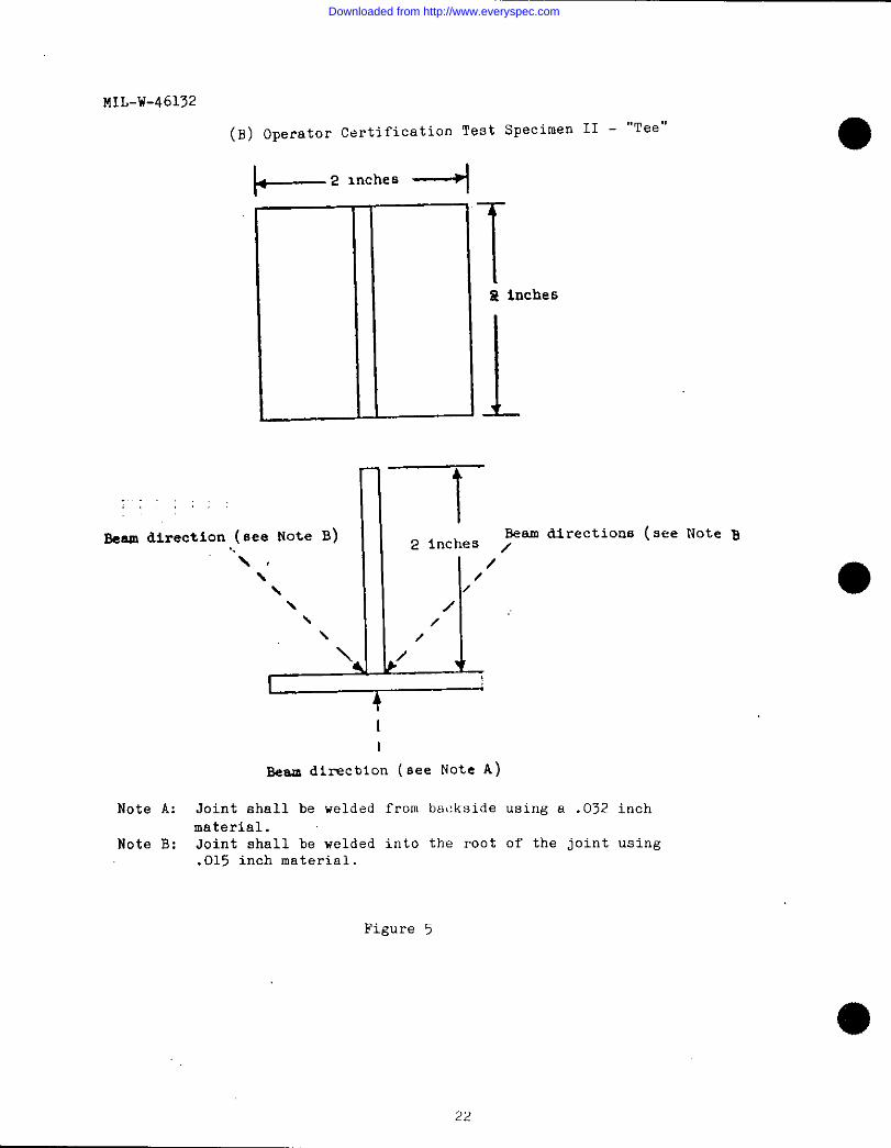
(B) Operator Certification Test
l+-’ l“’”s --l
Specimen II - “Tee”
Til inches
1
T;, ,, ,:
‘“’J’Jt
Beam direction (Bee Note B) Beam dlrectious (see Note B2 inches z
“\ , /\ /\ /\ /,\ /\ /\/
14II
Beam direcbion (see Note A)
Note A: Joint shall be welded from backside using a .032 inch
material.Note B: Joint shall be welded into the root of the joint using
.015 inch material.
Figure 5
22
Downloaded from http://www.everyspec.com
)MIL-W-46132
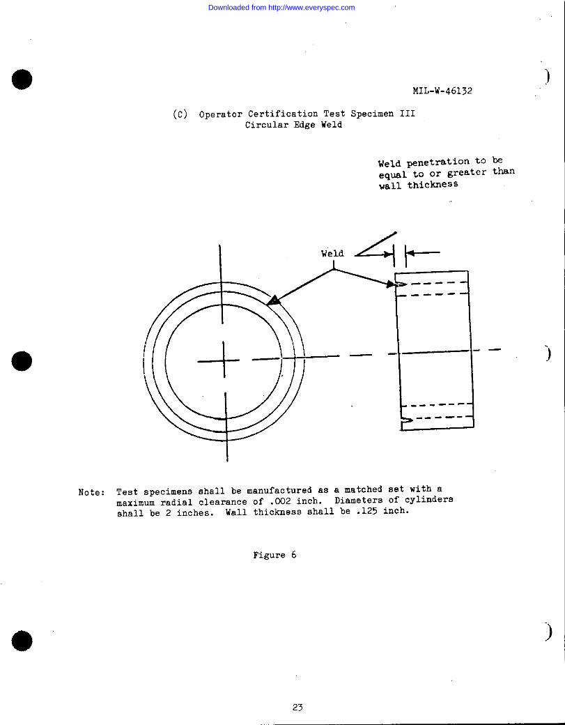
(C) Operator Certification Test Specimen IIICircular Edge Weld
Weld penetration tO beeqMl to or greater thanvail thiCklless
J- *I ----
Note: Test specimens shall be manufactured as a matched set with amaximum radial clearance of .002 inch. Diameters of cylinders
shall be 2 inches. Wall thickness shall be .125 inch.
)
Figure 6
)
23
Downloaded from http://www.everyspec.com
MIL-W-46132
$A
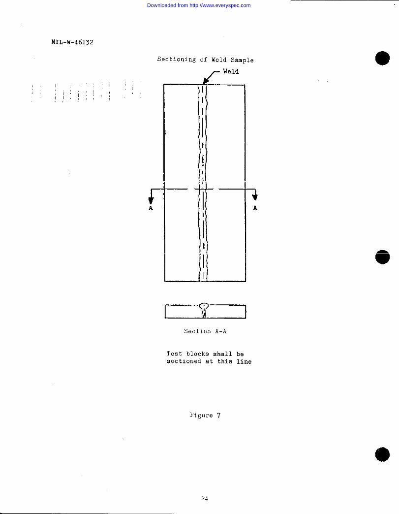
Sectioning of Weld Sample
—.
i
I
I
I
I
I-—
1 1’ I
Sec!tion A-A
Test blocks shallsectioned at this
beline
Figure 7
Downloaded from http://www.everyspec.com
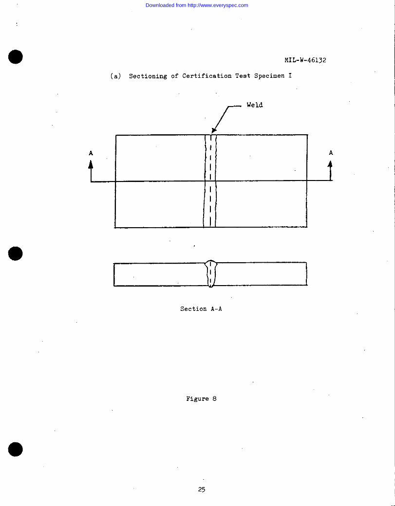
o(a) Sectioning of Certification
MIL-W-46132
Test Specimen I
f
Weld
i
A
I
II
II
III
Section A-A
Figure 8
25
Downloaded from http://www.everyspec.com
MIL-W-46132
t-
(b) Sectioning of Certification Test Specimen II
Section ,
We
-i
k-A
D = 1 x thinnestmemher L
3Figure9
(c) Sectioning of Certification Test Specl%n III
D
&
+
-L
)●section A-A
FigureLO
26
Downloaded from http://www.everyspec.com
MIL-w-b6132
Eiuild-up
Figure 11
[
~ Melt -through
)
)
:)
27
Downloaded from http://www.everyspec.com
K.V. MaDial Dial
Beam ModeBeam DiameterDialDecay % Dial
Fixture Description:
Travel Speed:RangeLinear In/Min Dial— —
Rotation: Timer
Range RPMDial Weld Die.
Pulsation:Pulse Width DialFulse freq. Dial
Beam Deflection:AC Total DC
Circle:Diameter
Other:
Approved By:
CERTIFIEDe
SCHEDULENumber ●
DateCompanyRepresentativePart NumberPart NameWeld Type
MaterialCleaning Procedure:
oualztyControlRequirement
TOOLING LAYOUT
Results and Comments
PHOTONACROGRAPH OFWELD STRUCTURE
m.
Mag Etchant
Figure 13. Sample of a certified weld schedule form
Downloaded from http://www.everyspec.com
—————.
K.V. MaDial Dial
Beam Mode
Beam DiameterDial
Decay % Dial
Fixture Description:
Distance of Work from Heat Shields:
Travel Speed:
& RangeLinear —InlMin —Dial
Rotation: Timer
Range RPM
Dial Weld Dia. _
Pulsation:
Pulse Width _
Pulse Freq.
Beam Deflection:
AC Total
Circle:Diameter
Dial
Dial
DC
Othcc
Approved By: .
CERTIFIED WEL a HEDULE
....
-s x...
Number
—.=— ——
Date
Company
Representative
Part Number
Part Name
Weld TYP~
Material:
Cleaning Procedure:
Quality Cmtrol Requirement
TOOLf NG LAYOUT
Results and Comments
PHOTOMACROGRAPH OFWELD STRUCTURE
Mag Etcha nt
‘igure 13. Sample of a certified weld schedule form
Downloaded from http://www.everyspec.com
MIL-w-46132
FINAL INSPECTIOI$REPORT
NumberSheet of
Company Weld Type
Part Name Joint Thickness
Part Number Material
Customer Shipper Weld Schedule‘QuantityAssemblies Tool Number Shipper
Quantity Detail Machine Date
(1) Pre-Weld Inspection
Part Fit-UpCleanlinessRemarks
w0
(2) Q.C. Samples
Sample #1Surface (20X)PenetrationQuality
Sample #2Surface (20X)PenetrationQuality
Sample #3
Surface (20X)PenetrationQuality
Final Visual Non-Destructive
Serial No. Imp. (20X) Tests Comments,
I I I II
Welded ByApproved Q.C. Ngr.
Figure 14. Sample of aoal inspection report form ●
Downloaded from http://www.everyspec.com