Embed Size (px)
Citation preview
CALICE Collaboration Meeting March 2014
Roman Pöschl
LAL Orsay
On behalf of:
D. Grondin, J. Giraud
J. Bonis, P. Cornebise, A. Thiebault, C. Bourgeois, A. Gonnin M. Frotin
Ecal mechanics
Expert work presented by a layman
CALICE Collaboration Meeting Argonne/IL March 2014
CALICE Collaboration Meeting March 2014
2
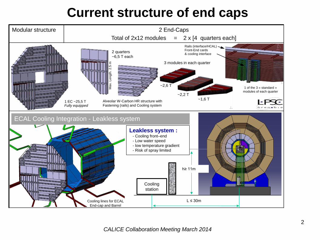
Modular structure 2 End-Caps
Total of 2x12 modules = 2 x [4 quarters each]
Rails (interface/HCAL)
Front-End cards & cooling interface
1 of the 3 « standard »
modules of each quarter
Alveolar W-Carbon HR structure with
Fastening (rails) and Cooling system
2 quarters
~6,5 T each
3 modules in each quarter
~1,6 T ~2,2 T
~2,6 T
Fully equipped 1 EC ~25,5 T
Cooling
station
h≥ 11m
L ≤ 30m
ECAL Cooling Integration - Leakless system
Cooling lines for ECAL
End-cap and Barrel
Max.
Length
. 2.5
m
Leakless system : - Cooling front–end
- Low water speed
- low temperature gradient
- Risk of spray limited
Current structure of end caps
CALICE Collaboration Meeting March 2014
3
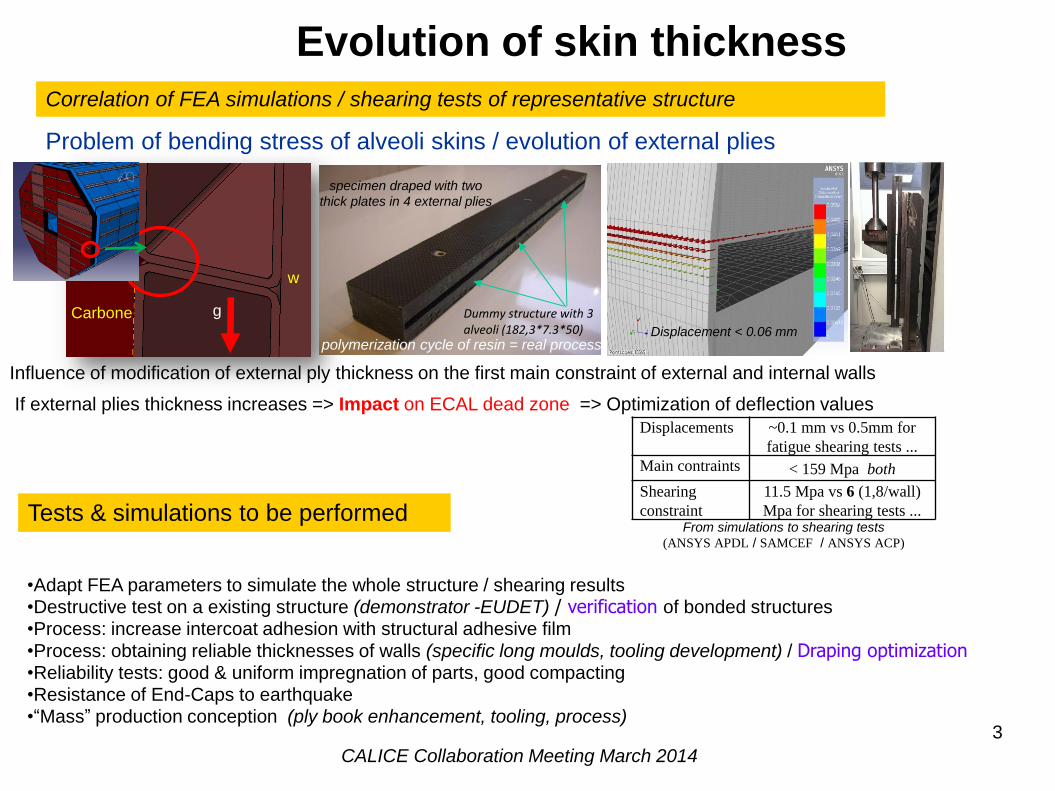
Correlation of FEA simulations / shearing tests of representative structure
Displacement < 0.06 mm
Displacements ~0.1 mm vs 0.5mm for
fatigue shearing tests ...
Main contraints < 159 Mpa both
Shearing
constraint
11.5 Mpa vs 6 (1,8/wall)
Mpa for shearing tests ... From simulations to shearing tests
(ANSYS APDL / SAMCEF / ANSYS ACP)
Tests & simulations to be performed
Carbone
w
g Dummy structure with 3 alveoli (182,3*7.3*50)
polymerization cycle of resin = real process
specimen draped with two
thick plates in 4 external plies
Problem of bending stress of alveoli skins / evolution of external plies
Influence of modification of external ply thickness on the first main constraint of external and internal walls
If external plies thickness increases => Impact on ECAL dead zone => Optimization of deflection values
•Adapt FEA parameters to simulate the whole structure / shearing results •Destructive test on a existing structure (demonstrator -EUDET) / verification of bonded structures •Process: increase intercoat adhesion with structural adhesive film
•Process: obtaining reliable thicknesses of walls (specific long moulds, tooling development) / Draping optimization •Reliability tests: good & uniform impregnation of parts, good compacting •Resistance of End-Caps to earthquake •“Mass” production conception (ply book enhancement, tooling, process)
Evolution of skin thickness
CALICE Collaboration Meeting March 2014
4
-500
0
500
1000
1500
2000
2500
0 0.2 0.4 0.6 0.8 1 1.2
Sh
eari
ng
Eff
ort
(N
)
Displacement (mm)
Force (N)Linear (Force (N))
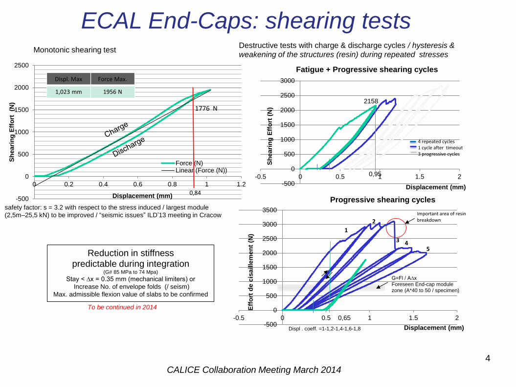
0,84
1776 N
Displ. Max Force Max.
1,023 mm 1956 N
safety factor: s = 3.2 with respect to the stress induced / largest module
(2,5m–25,5 kN) to be improved / “seismic issues” ILD’13 meeting in Cracow
Monotonic shearing test
-500
0
500
1000
1500
2000
2500
3000
-0.5 0 0.5 1 1.5 2
Sh
eari
ng
Eff
ort
(N
)
Displacement (mm)
Fatigue + Progressive shearing cycles
4 repeated cycles 1 cycle after timeout 3 progressive cycles
0,95
2158
Reduction in stiffness predictable during integration
(G# 85 MPa to 74 Mpa)
Stay < ∆x = 0.35 mm (mechanical limiters) or
Increase No. of envelope folds (/ seism)
Max. admissible flexion value of slabs to be confirmed
Displ . coeff. =1-1,2-1,4-1,6-1,8
G=Fl / A∆x
Foreseen End-cap module zone (A*40 to 50 / specimen)
Destructive tests with charge & discharge cycles / hysteresis &
weakening of the structures (resin) during repeated stresses
To be continued in 2014
Important area of resin breakdown
0,65 -500
0
500
1000
1500
2000
2500
3000
3500
-0.5 0 0.5 1 1.5 2
Eff
ort
de c
isaille
men
t (N
)
Displacement (mm)
Progressive shearing cycles
1
2
3 4 5
ECAL End-Caps: shearing tests
CALICE Collaboration Meeting March 2014
5
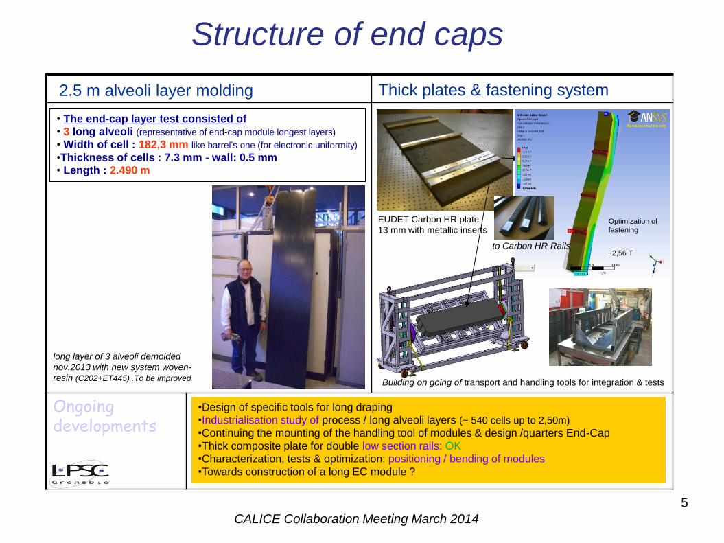
Ongoing developments
•Design of specific tools for long draping •Industrialisation study of process / long alveoli layers (~ 540 cells up to 2,50m)
•Continuing the mounting of the handling tool of modules & design /quarters End-Cap
•Thick composite plate for double low section rails: OK •Characterization, tests & optimization: positioning / bending of modules
•Towards construction of a long EC module ?
Thick plates & fastening system 2.5 m alveoli layer molding
• The end-cap layer test consisted of • 3 long alveoli (representative of end-cap module longest layers)
• Width of cell : 182,3 mm like barrel’s one (for electronic uniformity)
•Thickness of cells : 7.3 mm - wall: 0.5 mm • Length : 2.490 m
long layer of 3 alveoli demolded
nov.2013 with new system woven-
resin (C202+ET445) .To be improved Building on going of transport and handling tools for integration & tests
~2,56 T
Optimization of
fastening
to Carbon HR Rails
EUDET Carbon HR plate
13 mm with metallic inserts
Structure of end caps
CALICE Collaboration Meeting March 2014
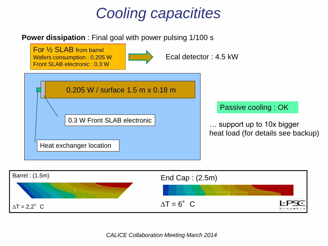
Power dissipation : Final goal with power pulsing 1/100 s
Barrel : (1.5m)
T = 2,2°C
For ½ SLAB from barrel
Wafers consumption : 0.205 W Front SLAB electronic : 0.3 W
Ecal detector : 4.5 kW
0.205 W / surface 1.5 m x 0.18 m
0.3 W Front SLAB electronic
Heat exchanger location
End Cap : (2.5m)
T = 6°C
Passive cooling : OK
Cooling capacitites
… support up to 10x bigger
heat load (for details see backup)
CALICE Collaboration Meeting March 2014
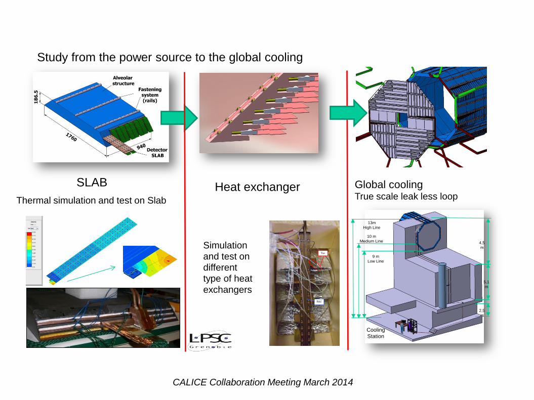
Study from the power source to the global cooling
SLAB Heat exchanger Global cooling True scale leak less loop
Simulation and test on
different type of heat
exchangers
Thermal simulation and test on Slab
cooling
station
13m
High Line
9 m
Low Line
10 m
Medium Line
2,5
m
5,1
m
4,5
m
Cooling
Station
CALICE Collaboration Meeting March 2014
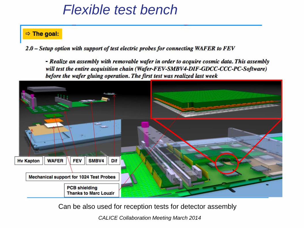
Flexible test bench
Can be also used for reception tests for detector assembly
CALICE Collaboration Meeting March 2014
9
9 Groupe XXX
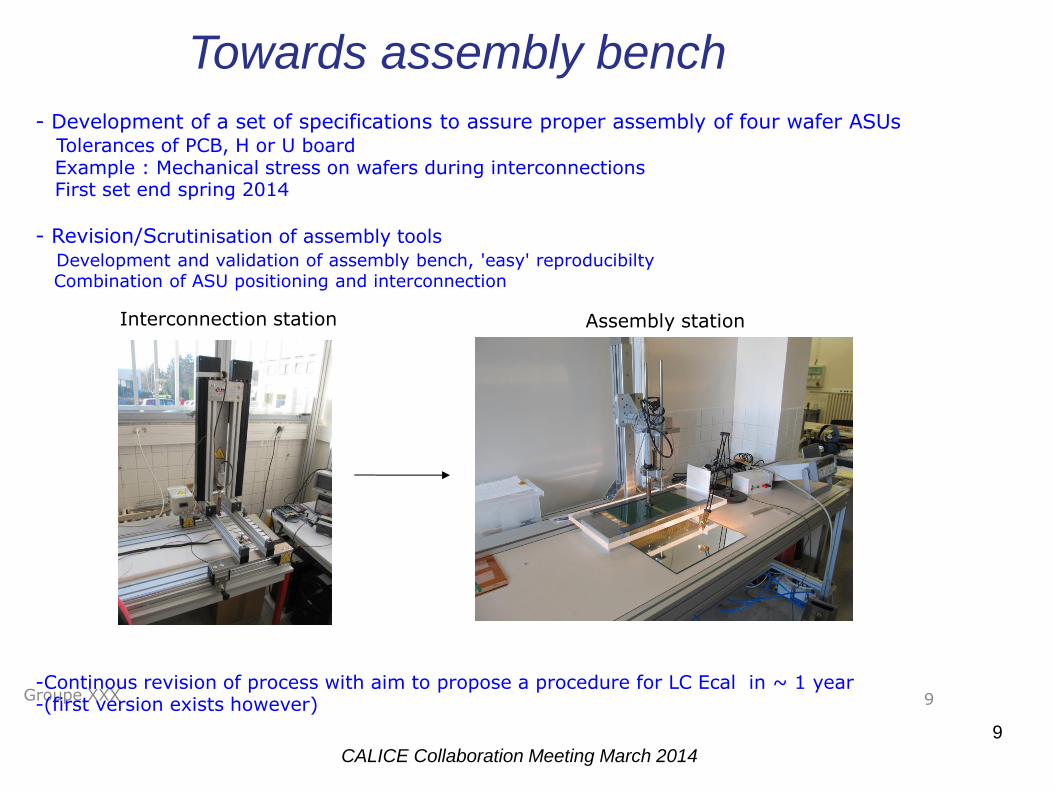
- Development of a set of specifications to assure proper assembly of four wafer ASUs Tolerances of PCB, H or U board Example : Mechanical stress on wafers during interconnections First set end spring 2014
- Revision/Scrutinisation of assembly tools
Development and validation of assembly bench, 'easy' reproducibilty Combination of ASU positioning and interconnection
-Continous revision of process with aim to propose a procedure for LC Ecal in ~ 1 year -(first version exists however)
Interconnection station Assembly station
Towards assembly bench
CALICE Collaboration Meeting March 2014
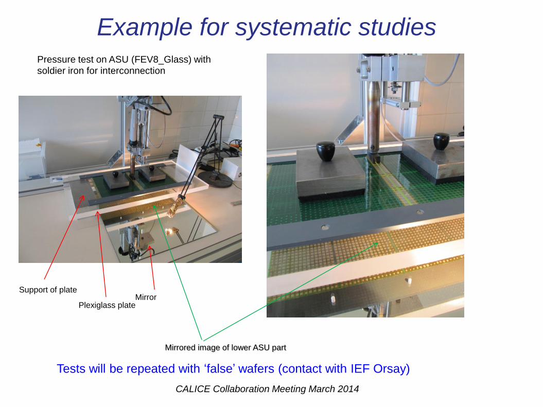
Pressure test on ASU (FEV8_Glass) with soldier iron for interconnection
Mirror Plexiglass plate
Support of plate
Mirrored image of lower ASU part
Example for systematic studies
Tests will be repeated with ‘false’ wafers (contact with IEF Orsay)
CALICE Collaboration Meeting March 2014
11 Groupe XXX
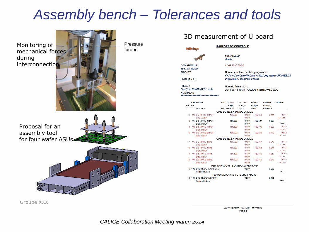
Pressure probe
3D measurement of U board
Monitoring of mechanical forces during interconnection
Proposal for an assembly tool for four wafer ASUs
Assembly bench – Tolerances and tools
CALICE Collaboration Meeting March 2014
Summary
- Studies for critical mechanical issues of end caps
Examination of shear forces (not only) on end cap walls
End cap demonstrator is part of AIDA2 proposal
- Continuous development of a cooling system
Ready for tech. Prototype, studies for ‘real’ size detector
Passive cooling seems to be feasible
- Towards assembly bench Flexible test beanch to assure tests before actual assembly
Production of short layers with 4 wafers but development of methods applicable to long layers
Definition of set of specifications to be respected for detector assembly
‘Where mechanics and electronics meet’
Aim is to present first proposal for mass production in ~ 1 year
Assembly bench is part of AIDA2 proposal
CALICE Collaboration Meeting March 2014
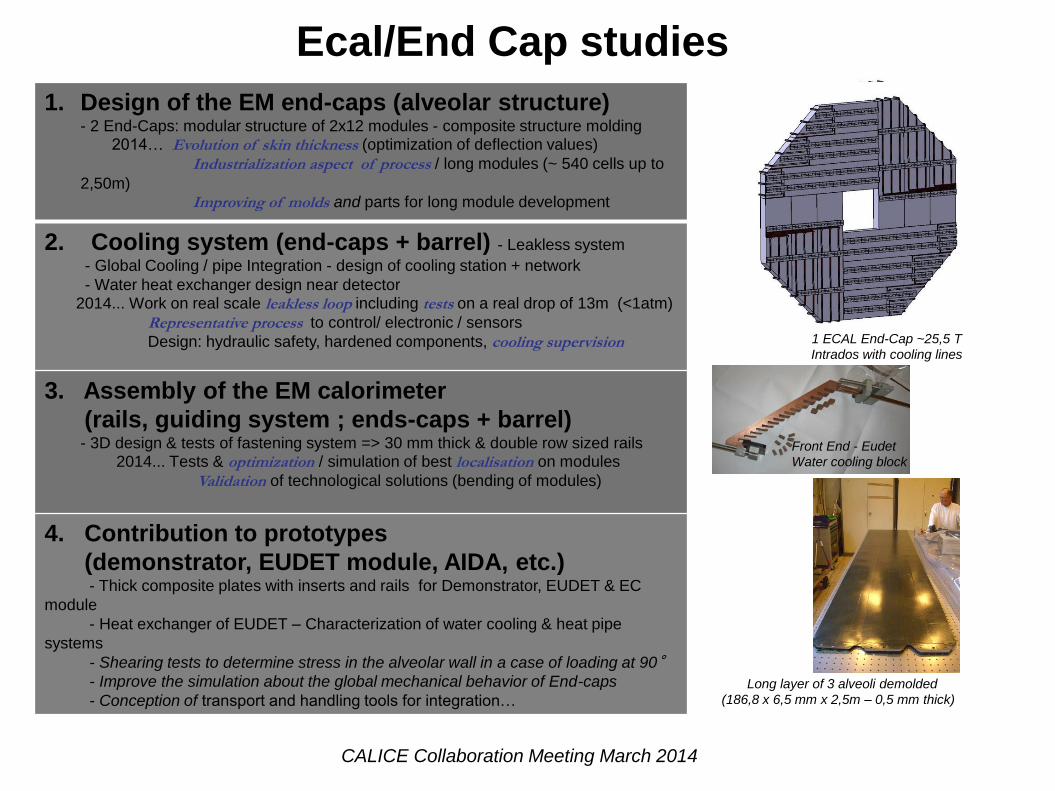
1 ECAL End-Cap ~25,5 T
Intrados with cooling lines
Long layer of 3 alveoli demolded
(186,8 x 6,5 mm x 2,5m – 0,5 mm thick)
Front End - Eudet
Water cooling block
1. Design of the EM end-caps (alveolar structure) - 2 End-Caps: modular structure of 2x12 modules - composite structure molding 2014… Evolution of skin thickness (optimization of deflection values)
Industrialization aspect of process / long modules (~ 540 cells up to
2,50m) Improving of molds and parts for long module development
2. Cooling system (end-caps + barrel) - Leakless system
- Global Cooling / pipe Integration - design of cooling station + network
- Water heat exchanger design near detector 2014... Work on real scale leakless loop including tests on a real drop of 13m (<1atm)
Representative process to control/ electronic / sensors
Design: hydraulic safety, hardened components, cooling supervision
3. Assembly of the EM calorimeter
(rails, guiding system ; ends-caps + barrel) - 3D design & tests of fastening system => 30 mm thick & double row sized rails 2014... Tests & optimization / simulation of best localisation on modules
Validation of technological solutions (bending of modules)
4. Contribution to prototypes
(demonstrator, EUDET module, AIDA, etc.) - Thick composite plates with inserts and rails for Demonstrator, EUDET & EC
module
- Heat exchanger of EUDET – Characterization of water cooling & heat pipe
systems
- Shearing tests to determine stress in the alveolar wall in a case of loading at 90°
- Improve the simulation about the global mechanical behavior of End-caps
- Conception of transport and handling tools for integration…
1 ECAL End-Cap ~25,5 T
Intrados with cooling lines
Long layer of 3 alveoli demolded
(186,8 x 6,5 mm x 2,5m – 0,5 mm thick)
Front End - Eudet
Water cooling block
Ecal/End Cap studies
CALICE Collaboration Meeting March 2014
14
Fro
nt
elec
tro
nic
(W
)
Waf
er (
W)
Tota
l EC
AL
(W)
Tem
par
atu
re v
aria
tio
n n
ear
th
e e
xch
ange
r
(°c)
(Th
erm
al c
on
tact
re
sist
ance
)
Tem
per
atu
re v
aria
tio
n a
lon
g th
e
SLA
B (
°c)
Tem
pér
atu
re a
t th
e en
d o
f th
e
SLA
B (
°c)
(wat
er t
emp
: 18
°c)
Remark
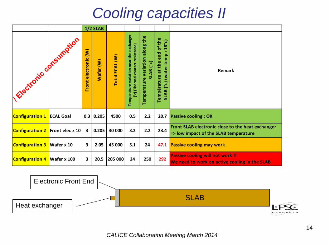
Configuration 1 ECAL Goal 0.3 0.205 4500 0.5 2.2 20.7 Passive cooling : OK
Configuration 2 Front elec x 10 3 0.205 30 000 3.2 2.2 23.4Front SLAB electronic close to the heat exchanger
=> low impact of the SLAB temperature
Configuration 3 Wafer x 10 3 2.05 45 000 5.1 24 47.1 Passive cooling may work
Configuration 4 Wafer x 100 3 20.5 205 000 24 250 292Passive cooling will not work !!
We need to work on active cooling in the SLAB
1/2 SLAB
SLAB
Electronic Front End
Heat exchanger
Cooling capacities II
CALICE Collaboration Meeting March 2014
11 Mars 2014 15
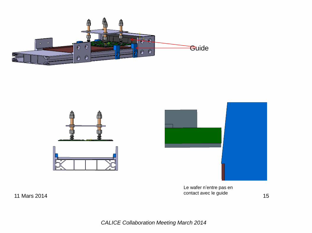
Le wafer n’entre pas en contact avec le guide
Guide
CALICE Collaboration Meeting March 2014
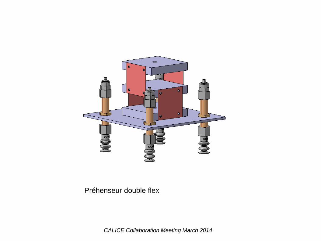
Préhenseur double flex


![The$Progress$On ECal R&D - Indico [Home]The$Progress$On ECal R&D 焦健斌 OnBehalf OfSoLIDECWorking Group 中国物理学会高能物理分会第十二届全国粒子物理学术会](https://img.pdfslide.us/doc/110x75/5a7cf66e7f8b9a2e358d29c5/theprogresson-ecal-rd-indico-hometheprogresson-ecal-rd-onbehalf.jpg)