Embed Size (px)
Citation preview
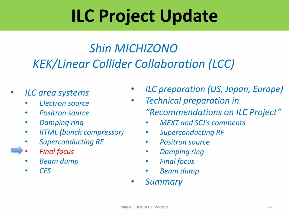
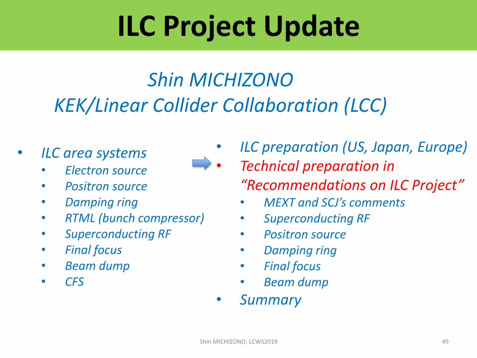
ILC Project Update
Shin MICHIZONOKEK/Linear Collider Collaboration (LCC)
• ILC area systems• Electron source• Positron source• Damping ring• RTML (bunch compressor)• Superconducting RF• Final focus• Beam dump• CFS
Shin MICHIZONO, LCWS2019 1
• ILC preparation (US, Japan, Europe)• Technical preparation in
“Recommendations on ILC Project”• MEXT and SCJ’s comments• Superconducting RF • Positron source• Damping ring• Final focus• Beam dump
• Summary
e- Source
e+ Main Liinac
e+ Source
e- Main Linac
Damping Ring
Beam dump
Interaction point
Physics Detectors
• Creating particles Sources
– polarized elections/positrons
• High quality beams Damping ring
– Low emittance beams• Small beam size (small beam spread)
• Parallel beam (small momentum spread)
• Beam transport RTML (bunch compressor)
• Acceleration Main linac
– superconducting radio frequency (SRF)
• Getting them collided Final focus
– nano-meter beams
• Go to Beam dump
Technology of the ILC
Shin MICHIZONO, LCWS2019 2
e+ RTML
e- RTML

ILC beam structureThe ILC is operated at a repetition rate of 5 Hz.A beam pulse comes every 200 milliseconds.。
Each beam pulse includes 1,312 bunches.Bunch interval is 554 nanoseconds.
Each bunch consists of 20 billion electrons (3.2 nC).Shin MICHIZONO, LCWS2019 3

ILC Project Update
Shin MICHIZONOKEK/Linear Collider Collaboration (LCC)
• ILC area systems• Electron source• Positron source• Damping ring• RTML (bunch compressor)• Superconducting RF• Final focus• Beam dump• CFS
Shin MICHIZONO, LCWS2019 4
• ILC preparation (US, Japan, Europe)• Technical preparation in
“Recommendations on ILC Project”• MEXT and SCJ’s comments• Superconducting RF • Positron source• Damping ring• Final focus• Beam dump
• Summary
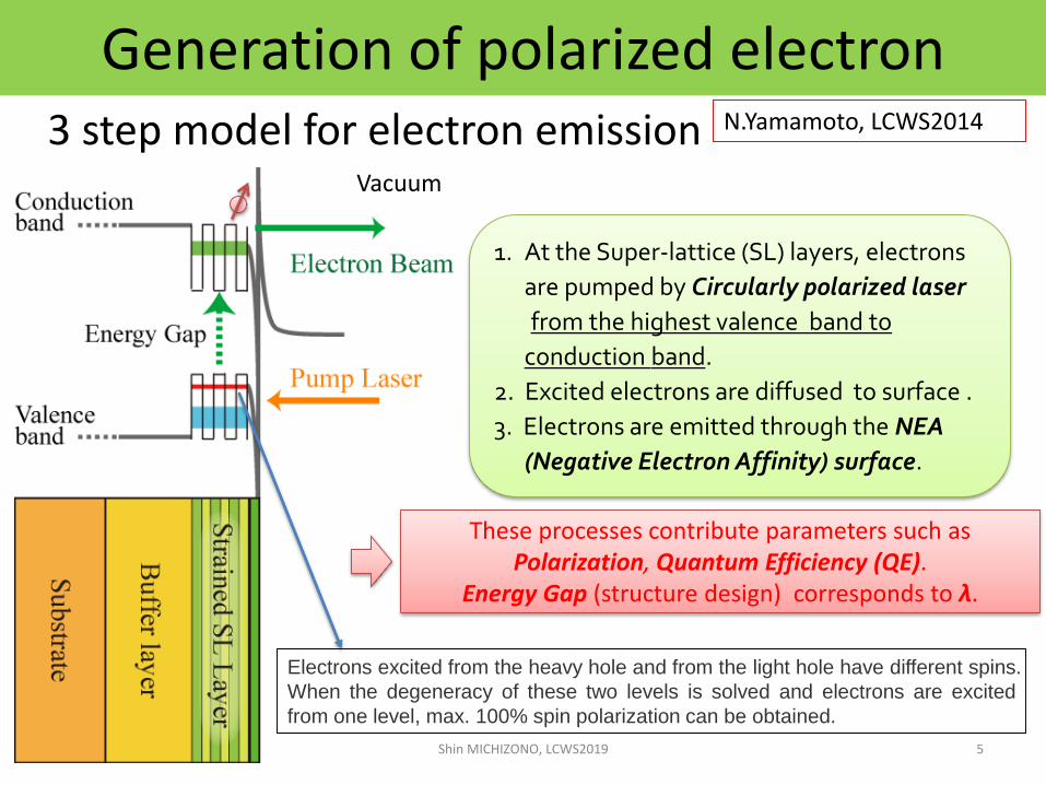
Generation of polarized electron3 step model for electron emission
1. At the Super-lattice (SL) layers, electrons
are pumped by Circularly polarized laser
from the highest valence band to
conduction band.
2. Excited electrons are diffused to surface .
3. Electrons are emitted through the NEA
(Negative Electron Affinity) surface.
These processes contribute parameters such as Polarization, Quantum Efficiency (QE).
Energy Gap (structure design) corresponds to λ.
Vacuum
5
N.Yamamoto, LCWS2014
Shin MICHIZONO, LCWS2019
Electrons excited from the heavy hole and from the light hole have different spins.
When the degeneracy of these two levels is solved and electrons are excited
from one level, max. 100% spin polarization can be obtained.
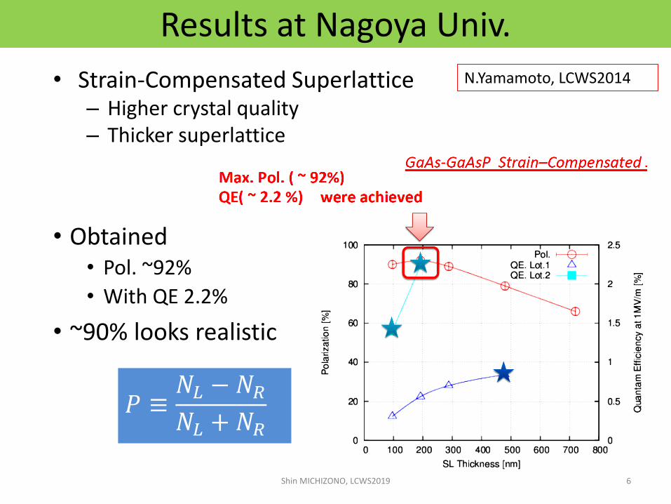
Results at Nagoya Univ.
• Strain-Compensated Superlattice– Higher crystal quality– Thicker superlattice
• Obtained• Pol. ~92%
• With QE 2.2%
• ~90% looks realistic
6
N.Yamamoto, LCWS2014
Shin MICHIZONO, LCWS2019
𝑃 ≡𝑁𝐿 − 𝑁𝑅𝑁𝐿 + 𝑁𝑅
7
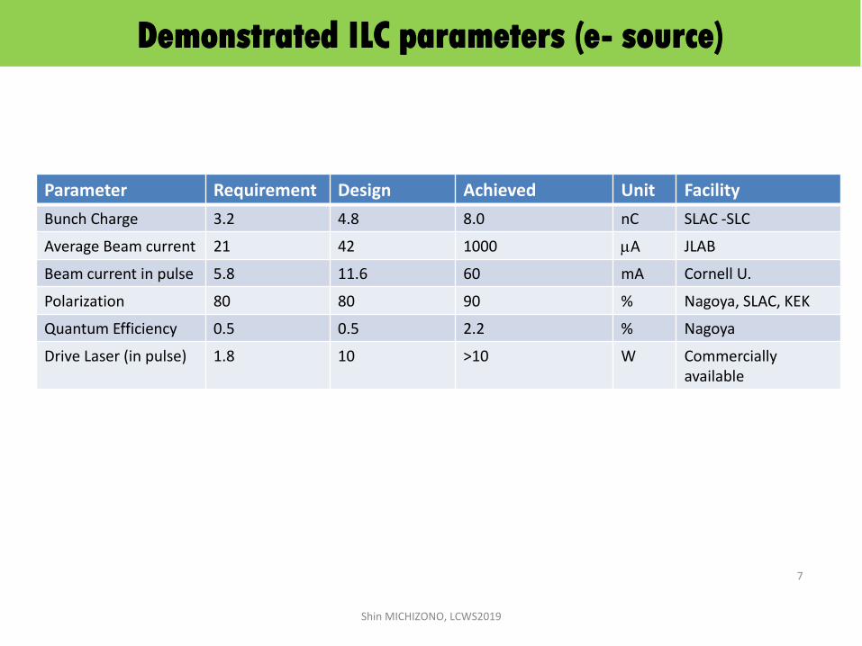
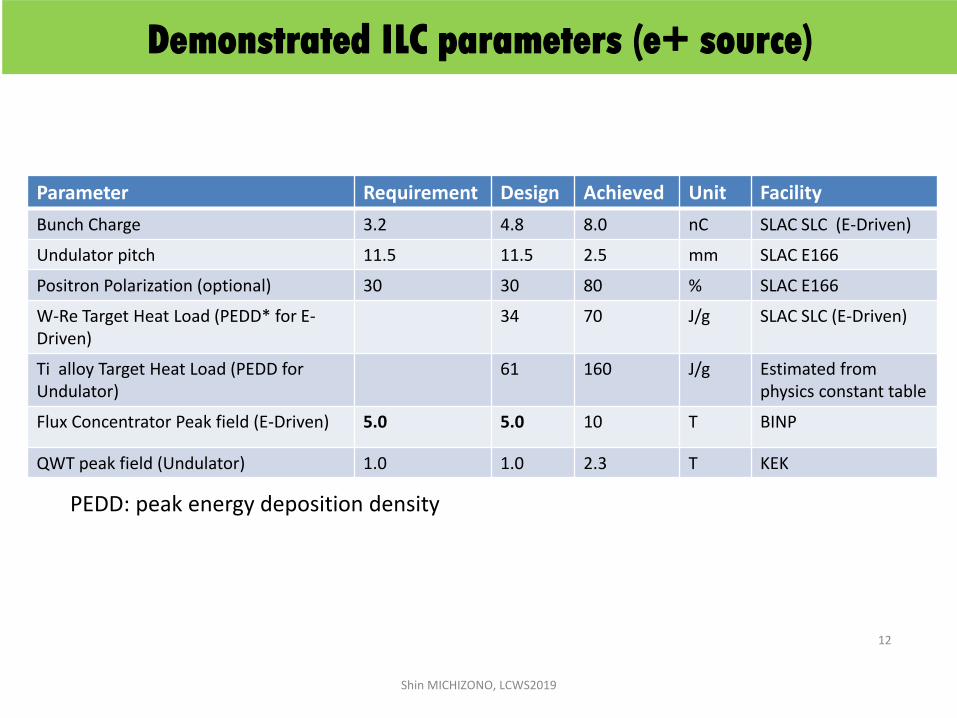
Parameter Requirement Design Achieved Unit Facility
Bunch Charge 3.2 4.8 8.0 nC SLAC -SLC
Average Beam current 21 42 1000 mA JLAB
Beam current in pulse 5.8 11.6 60 mA Cornell U.
Polarization 80 80 90 % Nagoya, SLAC, KEK
Quantum Efficiency 0.5 0.5 2.2 % Nagoya
Drive Laser (in pulse) 1.8 10 >10 W Commercially available
Shin MICHIZONO, LCWS2019
Demonstrated ILC parameters (e- source)
ILC Project Update
Shin MICHIZONOKEK/Linear Collider Collaboration (LCC)
• ILC area systems• Electron source• Positron source• Damping ring• RTML (bunch compressor)• Superconducting RF• Final focus• Beam dump• CFS
Shin MICHIZONO, LCWS2019 8
• ILC preparation (US, Japan, Europe)• Technical preparation in
“Recommendations on ILC Project”• MEXT and SCJ’s comments• Superconducting RF • Positron source• Damping ring• Final focus• Beam dump
• Summary
125GeVelectron
QWT
9Shin MICHIZONO, LCWS2019
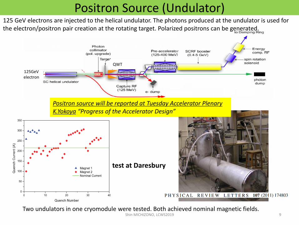
Positron Source (Undulator)125 GeV electrons are injected to the helical undulator. The photons produced at the undulator is used for the electron/positron pair creation at the rotating target. Polarized positrons can be generated.
Two undulators in one cryomodule were tested. Both achieved nominal magnetic fields.
test at Daresbury
Positron source will be reported at Tuesday Accelerator PlenaryK.Yokoya “Progress of the Accelerator Design”

10Shin MICHIZONO, LCWS2019
Positron Source (e-Driven)Extra 3GeV linac is used for the positron generation. High energy electrons are not necessary. (Electron independent commissioning is possible. However, polarization is not available.)
Each beam pulse includes 33x2 bunches.
Total 20x5 beam pulses per sec.
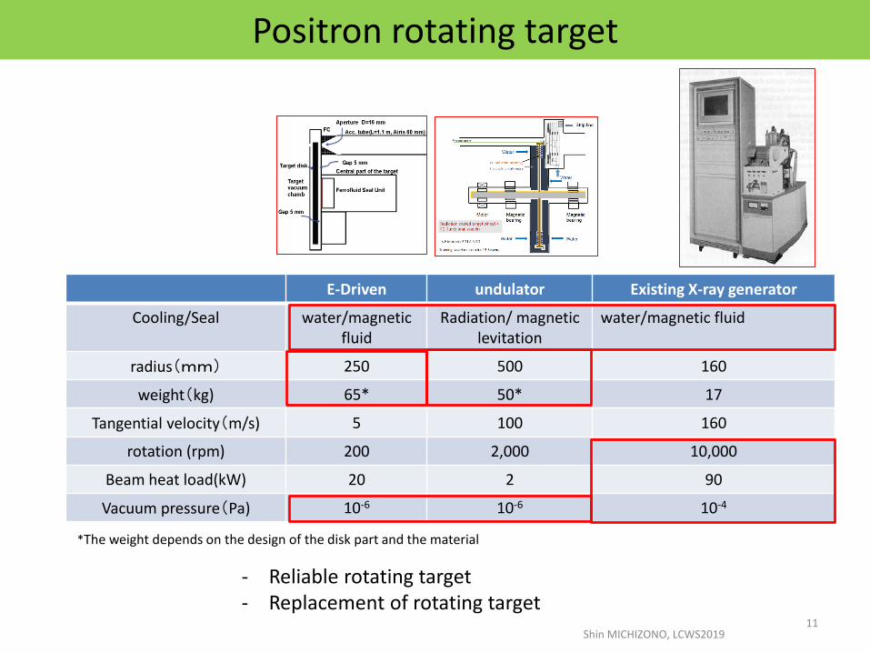
E-Driven undulator Existing X-ray generator
Cooling/Seal water/magnetic fluid
Radiation/ magnetic levitation
water/magnetic fluid
radius(mm) 250 500 160
weight(kg) 65* 50* 17
Tangential velocity(m/s) 5 100 160
rotation (rpm) 200 2,000 10,000
Beam heat load(kW) 20 2 90
Vacuum pressure(Pa) 10-6 10-6 10-4
Positron rotating target
*The weight depends on the design of the disk part and the material
Shin MICHIZONO, LCWS201911
- Reliable rotating target - Replacement of rotating target
12
Parameter Requirement Design Achieved Unit Facility
Bunch Charge 3.2 4.8 8.0 nC SLAC SLC (E-Driven)
Undulator pitch 11.5 11.5 2.5 mm SLAC E166
Positron Polarization (optional) 30 30 80 % SLAC E166
W-Re Target Heat Load (PEDD* for E-Driven)
34 70 J/g SLAC SLC (E-Driven)
Ti alloy Target Heat Load (PEDD for Undulator)
61 160 J/g Estimated from physics constant table
Flux Concentrator Peak field (E-Driven) 5.0 5.0 10 T BINP
QWT peak field (Undulator) 1.0 1.0 2.3 T KEK
Shin MICHIZONO, LCWS2019
Demonstrated ILC parameters (e+ source)
PEDD: peak energy deposition density

ILC Project Update
Shin MICHIZONOKEK/Linear Collider Collaboration (LCC)
• ILC area systems• Electron source• Positron source• Damping ring• RTML (bunch compressor)• Superconducting RF• Final focus• Beam dump• CFS
Shin MICHIZONO, LCWS2019 13
• ILC preparation (US, Japan, Europe)• Technical preparation in
“Recommendations on ILC Project”• MEXT and SCJ’s comments• Superconducting RF • Positron source• Damping ring• Final focus• Beam dump
• Summary
●Existing
●Plan
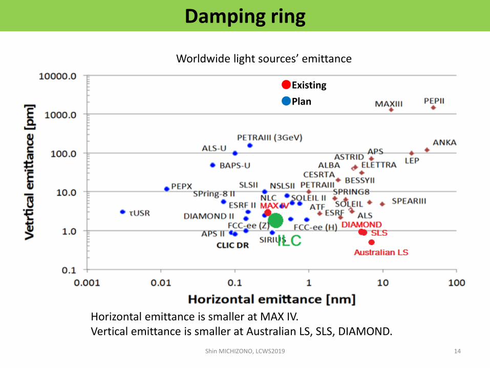
Damping ring
Shin MICHIZONO, LCWS2019 14
Horizontal emittance is smaller at MAX IV.Vertical emittance is smaller at Australian LS, SLS, DIAMOND.
Worldwide light sources’ emittance

Extracted beam signal
Bunch extraction test at ATF
Beam extraction by fast kicker
T.Naito et al., PR ST-AB 14 (2011) 051002 T.Naito et al., NIM A 571 (2007) 599.
Fast Kicker waveform
ATF exp. ILC
DR 5.60 ns 6.15 ns
extraction 302-308ns 554 ns
Bunch-space at ATF exp. and ILC
Shin MICHIZONO, LCWS2019 15
Shin MICHIZONO, LCWS2019 16
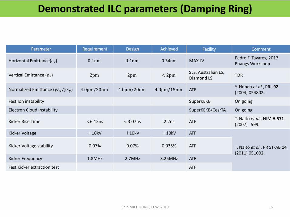
Demonstrated ILC parameters (Damping Ring)
Parameter Requirement Design Achieved Facility Comment
Horizontal Emittance(𝜀𝑥) 0.4nm 0.4nm 0.34nm MAX-IVPedro F. Tavares, 2017 Phangs Workshop
Vertical Emittance (𝜀𝑦) 2pm 2pm < 2pmSLS, Australian LS, Diamond LS
TDR
Normalized Emittance (𝛾𝜀𝑥/𝛾𝜀𝑦) 4.0μm/20nm 4.0μm/20nm 4.0μm/15nm ATFY. Honda et al., PRL 92(2004) 054802.
Fast Ion instability SuperKEKB On going
Electron Cloud Instability SuperKEKB/CesrTA On going
Kicker Rise Time < 6.15ns < 3.07ns 2.2ns ATFT. Naito et al., NIM A 571(2007) 599.
Kicker Voltage ±10kV ±10kV ±10kV ATF
T. Naito et al., PR ST-AB 14(2011) 051002.
Kicker Voltage stability 0.07% 0.07% 0.035% ATF
Kicker Frequency 1.8MHz 2.7MHz 3.25MHz ATF
Fast Kicker extraction test ATF

ILC Project Update
Shin MICHIZONOKEK/Linear Collider Collaboration (LCC)
• ILC area systems• Electron source• Positron source• Damping ring• RTML (bunch compressor)• Superconducting RF• Final focus• Beam dump• CFS
Shin MICHIZONO, LCWS2019 17
• ILC preparation (US, Japan, Europe)• Technical preparation in
“Recommendations on ILC Project”• MEXT and SCJ’s comments• Superconducting RF • Positron source• Damping ring• Final focus• Beam dump
• Summary

RF cavity
Chicane, etc.
Energy difference in the bunch
The optical path difference can be made by the difference in energy.
RTML (Bunch compressor)
“Bunch compressor” compresses the bunch from 6 mm to 0.3 mm before entering the main linac (15GeV).This final bunch length is one or more orders of magnitude longer than FEL etc., so it is not difficult (eg SACLA; FWHM 3 "μm").
If the phase of the RF cavity is jittered, jitter occurs in the arrival time of the beam at the collision point. Therefore, the phase jitter of the RF cavity of the ILC bunch compressor must be kept within 0.24 ° (0.15 mm). (but not difficult compared with the XFEL requirements of ~0.01 °)
Shin MICHIZONO, LCWS2019 18

Shin MICHIZONO, LCWS2019 19
Demonstrated ILC parameters (RTML)
Parameter Requirement Design Achieved Facility Comment
BC phase error 0.24° 0.042° KEK-STF M.Omet, Ph.Dthesis (2014)BC amplitude error 0.5% 0.041% KEK-STF
Horizontal emittance increase (𝛾𝜀𝑥)
1μm
RTML (0.47μm) ,BC (0.43μm),ML (0.00μm), total (0.90μm)
In simulation TDR
Vertical emittanceincrease (𝛾𝜀𝑦)
15 nmRTML (6.4nm) ,ML (4.5nm),total (10.9nm)
In simulation TDR
ILC Project Update
Shin MICHIZONOKEK/Linear Collider Collaboration (LCC)
• ILC area systems• Electron source• Positron source• Damping ring• RTML (bunch compressor)• Superconducting RF• Final focus• Beam dump• CFS
Shin MICHIZONO, LCWS2019 20
• ILC preparation (US, Japan, Europe)• Technical preparation in
“Recommendations on ILC Project”• MEXT and SCJ’s comments• Superconducting RF • Positron source• Damping ring• Final focus• Beam dump
• Summary
Electron Source
Damping Ring
Positron Linac
Electron Linac
Detectors
Positron Source
Beam dump
Beam dump
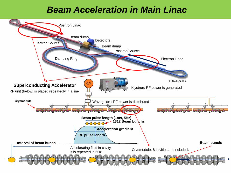
Superconducting Accelerator
DESY Euro-XFEL
RF unit (below) is placed repeatedly in a lineKlystron: RF power is generated
Waveguide : RF power is distributed
Beam bunch:
Cryomodule
Cryomodule: 8 cavities are included。
Interval of beam bunch
Accelerating field in cavity
It is repeated in 5Hz
Acceleration gradient
RF pulse length
Beam pulse length (1ms, 5Hz)1312 Beam bunchs
Beam Acceleration in Main Linac
Shin MICHIZONO, LCWS2019 21

Main Linac at the ILC
22
Tunnel
RTMLRF Distribution
Cryomodules
Shin MICHIZONO, LCWS2019
RF Power Source
# of SRF cavities ~8,000
12 m
~900 cyomodules

Matured SRF technologies
23
Shin MICHIZONO, LCWS2019
R. Geng (JLAB)
ILC:Accept:35 MV/m +/-20%Operate: 31.5MV/m +/-20%
European XFEL800 cavities (10% of ILC ML)

ILC SRF Global Integration Model
FNAL/ANL
CornellJLABKEK
DESY, INFNCERN
SLAC, LCLS-IICEA-Saclay, LAL-Orsay
IHEP, PKU
IUAC,RRCAT
TRIUMF
Hub-Lab
Hub-Lab
Hub-Lab
Hub-Lab
Industryworldwide
ILC Host/Hub-Lab
Hub-
Lab
Hub-lab:
regionally
hosting
integration
& Test Industry:
manufacturing
components
Shin MICHIZONO, LCWS2019 24
~8,000 x 1.1(Yield = 90%)
~ 9,000 cavities of mass-production
Parameter Requirement Achieved Comment
Acc. Gradient in the
cryomodule
31.5 MV/m 32.5MV/m (PXFEL-1, DESY)
31.5MV/m(CM-2, ASTA)
32 MV/m(CM-1&2a,STF)
DESY-Proto-XFEL (ILC-TDR V3, Part-1,
p43)
FNAL-ASTA (E. Harms, AWLC14 May
2014)
STF(KEK news May 22,2019)
Average Q0 in cryomodule 1010 -- (PXFEL-1, DESY)
0.9x10¹⁰(CM-2, ASTA)
0.7x10¹⁰(CM-1&2a,STF)
FNAL-ASTA (E. Harms, AWLC14 May
2014)
KEK-STF report (Y. Yamamoto, STF,2016)
Acc. Gradient at vertical
test
≧35(±20%)
MV/m
≧90%yield
<37 MV/m>
~94%
TDR vol-3 part I, Chapter 2.3
Beam current 5.78mA 6mA (800μs beam pulse length)
DESY-FLASH 9mA-study,
TDR vol-3 part I, p.80
Number of bunches 1312 2400 (800μs beam pulse length)
Bunch charge 3.2nC 3nC (600μs beam pulse length)
2nC (800μs beam pulse length)
Bunch space 554ns 333ns
Bunch length 727μs 800μs
Rf pulse width 1.65ms >1.65ms
RF pulse repetition 5Hz 10Hz DESY XFEL
Shin MICHIZONO, LCWS2019 25
Demonstrated ILC parameters (SRF)
ILC Project Update
Shin MICHIZONOKEK/Linear Collider Collaboration (LCC)
• ILC area systems• Electron source• Positron source• Damping ring• RTML (bunch compressor)• Superconducting RF• Final focus• Beam dump• CFS
Shin MICHIZONO, LCWS2019 26
• ILC preparation (US, Japan, Europe)• Technical preparation in
“Recommendations on ILC Project”• MEXT and SCJ’s comments• Superconducting RF • Positron source• Damping ring• Final focus• Beam dump
• Summary
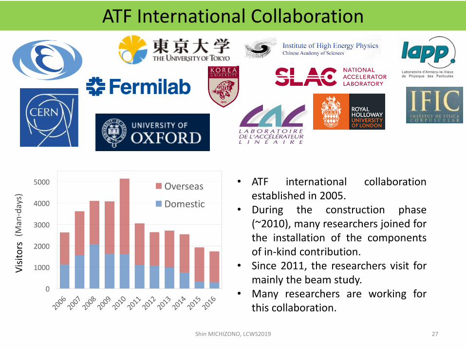
ATF International Collaboration
• ATF international collaborationestablished in 2005.
• During the construction phase(~2010), many researchers joined forthe installation of the componentsof in-kind contribution.
• Since 2011, the researchers visit formainly the beam study.
• Many researchers are working forthis collaboration.
Vis
ito
rs
Shin MICHIZONO, LCWS2019 27

Layout of ILC
Develop the nanometer beam technologies for ILC Key of the luminosity
maintenance 7.7 nm beam at IP (ILC250)
ATF/ATF2: Accelerator Test Facility
1.3 GeV S-band Electron LINAC (~70m)
Damping Ring (~140m)Low emittance electron beam
ATF2: Final Focus Test BeamlineGoal 1:Establish the technique for small beam Goal 2: Stabilize beam position
Shin MICHIZONO, LCWS2019
28

Efficient beam collision can be achieved with high-speed feedback that measures the initial beam position of the pulse train and corrects the position of subsequent bunches in the train.Feedback latency should be less than bunch space.
Depending on the relative position of the beam, beams are greatly scattered by the beam-beam effect.
ILC bunch structure
FONT* Bunch train feedback at final focus
BPM
Kicker
IP
The first bunch does not collide, but the second and subsequent bunches will collide.
CAIN simulation
Shin MICHIZONO, LCWS2019
29
The position of the beam between pulse trains shifts due to ground vibrations and equipment noise.On the other hand, the position of the beam does not change significantly in the pulse train.
*Feedback On Nanosecond Timescaleshttps://journals.aps.org/prab/abstract/10.1103/PhysRevAccelBeams.21.122802
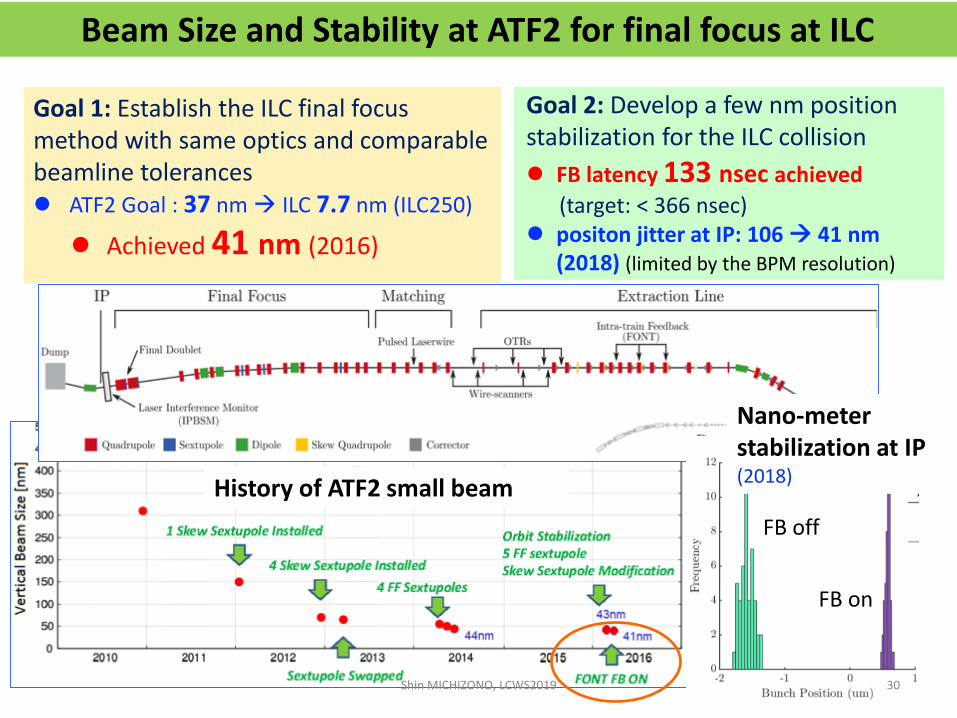
Goal 1: Establish the ILC final focus method with same optics and comparable beamline tolerances ATF2 Goal : 37 nm ILC 7.7 nm (ILC250)
Achieved 41 nm (2016)
Beam Size and Stability at ATF2 for final focus at ILC
Goal 2: Develop a few nm position stabilization for the ILC collision
FB latency 133 nsec achieved
(target: < 366 nsec) positon jitter at IP: 106 41 nm
(2018) (limited by the BPM resolution)
History of ATF2 small beam
Nano-meter stabilization at IP(2018)
FB off
FB on
Shin MICHIZONO, LCWS2019 30
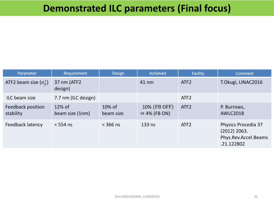
Parameter Requirement Design Achieved Facility Comment
ATF2 beam size (𝜎𝑦∗) 37 nm (ATF2
design)41 nm ATF2 T.Okugi, LINAC2016
ILC beam size 7.7 nm (ILC design) ATF2
Feedback position stability
12% of beam size (1nm)
10% of beam size
10% FB OFF⇒ 4% (FB ON)
ATF2 P. Burrows, AWLC2018
Feedback latency < 554 ns < 366 ns 133 ns ATF2 Physics Procedia 37 (2012) 2063.Phys.Rev.Accel.Beams.21.122802
Demonstrated ILC parameters (Final focus)
Shin MICHIZONO, LCWS2019 31
ILC Project Update
Shin MICHIZONOKEK/Linear Collider Collaboration (LCC)
• ILC area systems• Electron source• Positron source• Damping ring• RTML (bunch compressor)• Superconducting RF• Final focus• Beam dump• CFS
Shin MICHIZONO, LCWS2019 32
• ILC preparation (US, Japan, Europe)• Technical preparation in
“Recommendations on ILC Project”• MEXT and SCJ’s comments• Superconducting RF • Positron source• Damping ring• Final focus• Beam dump
• Summary

33
Water beam dump Req. Des. Achieved unit Comment
ILC 250GeV 2.6 17 - MW Designed for 500GeV beam
SLAC 2mile LINAC - 2.2 0.75 MW ILC beam dump prototype
CEBAF 0.9 1.0 0.73 MW In operation at Jefferson Lab from the 90s to the present. 2 units (2 beam lines). Composite type with aluminum plates arranged in water.
ILC beam dump is designed for 1TeV collision energy, and ILC250 has enough margin.
Beam dump
Shin MICHIZONO, LCWS2019
Shin MICHIZONO, LCWS2019 34
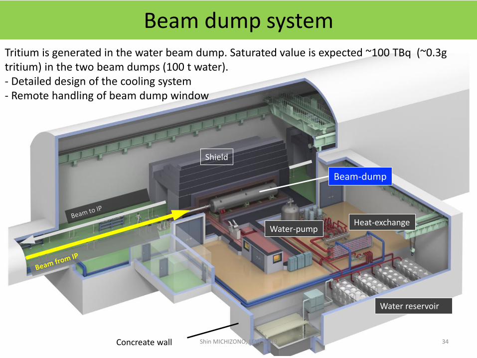
Beam-dump
Shield
Water-pump
Water reservoir
Heat-exchange
Concreate wall
Beam dump systemTritium is generated in the water beam dump. Saturated value is expected ~100 TBq (~0.3g tritium) in the two beam dumps (100 t water).- Detailed design of the cooling system- Remote handling of beam dump window
ILC Project Update
Shin MICHIZONOKEK/Linear Collider Collaboration (LCC)
• ILC area systems• Electron source• Positron source• Damping ring• RTML (bunch compressor)• Superconducting RF• Final focus• Beam dump• CFS
Shin MICHIZONO, LCWS2019 35
• ILC preparation (US, Japan, Europe)• Technical preparation in
“Recommendations on ILC Project”• MEXT and SCJ’s comments• Superconducting RF • Positron source• Damping ring• Final focus• Beam dump
• Summary
Electron Linac
Positron Linac
North
IP
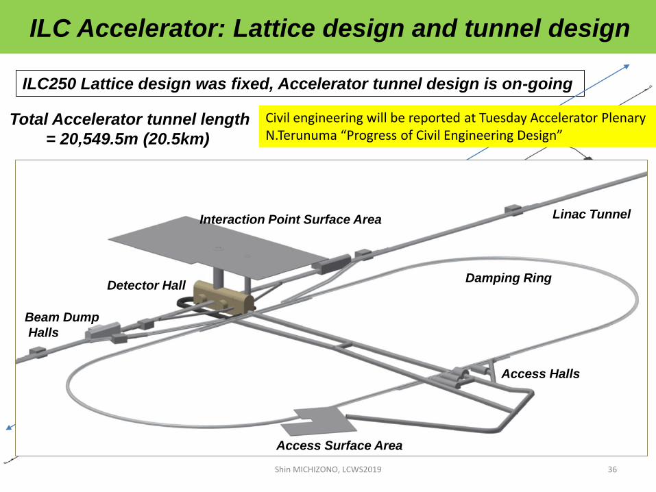
Total Accelerator tunnel length
= 20,549.5m (20.5km)
ILC250 Lattice design was fixed, Accelerator tunnel design is on-going
20.5km
ILC Accelerator: Lattice design and tunnel design
Damping Ring
Interaction Point Surface Area
Detector HallDamping Ring
Linac Tunnel
Access Surface Area
Access Halls
Beam Dump
Halls
Shin MICHIZONO, LCWS2019 36
Civil engineering will be reported at Tuesday Accelerator PlenaryN.Terunuma “Progress of Civil Engineering Design”

Shin MICHIZONO, LCWS2019 37

Tunnel design for Kitakami Candidate Site (ILC250GeV 20.5km)38
Colliding point
Damping RingElectron Linac
Positron Linac
Rey.hori/KEK
Bird’s eye view of ILC in Kitakami candidate site
Shin MICHIZONO, LCWS2019
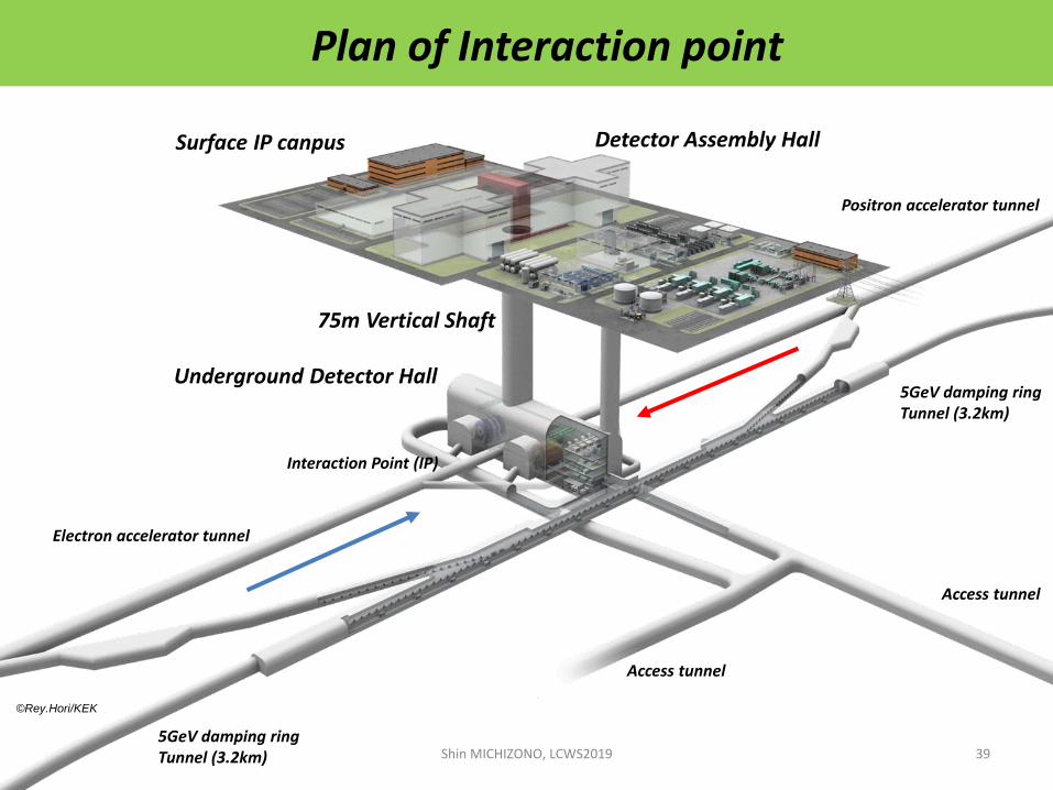
Plan of Interaction point
5GeV damping ringTunnel (3.2km)
Interaction Point (IP)
5GeV damping ringTunnel (3.2km)
Electron accelerator tunnel
Positron accelerator tunnel
Underground Detector Hall
75m Vertical Shaft
Surface IP canpus
Access tunnel
Access tunnel
©Rey.Hori/KEK
Detector Assembly Hall
Shin MICHIZONO, LCWS2019 39

Surface-to-Underground access-tunnel
Access Tunnel (10% down-slope tunnel, about 1km length)
AcceleratorTunnel
Underground Access Hall
Surface Access Station
Shin MICHIZONO, LCWS2019 40
ILC Project Update
Shin MICHIZONOKEK/Linear Collider Collaboration (LCC)
• ILC area systems• Electron source• Positron source• Damping ring• RTML (bunch compressor)• Superconducting RF• Final focus• Beam dump• CFS
Shin MICHIZONO, LCWS2019 41
• ILC preparation (US, Japan, Europe)• Technical preparation in
“Recommendations on ILC Project”• MEXT and SCJ’s comments• Superconducting RF • Positron source• Damping ring• Final focus• Beam dump
• Summary

ILC preparation plan/activity
Shin MICHIZONO, LCWS2019 42
USAUS-Japan Joint Research on ILC Cost ReductionHigh Luminosity ILC Workshop (May 2019) @FNALhttps://indico.fnal.gov/event/20759/https://arxiv.org/abs/1910.01276
European ILC preparation plan as “E-JADE” reporthttps://www.e-jade.eu/sites/sites_custom/site_e-jade/content/e49893/e65922/e73204/ILC-EIPP.E-JADE.v2.12.20180703.pdf
KEK ILC action planhttps://www.kek.jp/en/newsroom/KEK-ILC_ActionPlan_Addendum-EN%20%281%29.pdf
issued on Jan. 2016.Addendum issued on Jan.2018.
European Strategy inputThe International Linear Collider A European Prospective
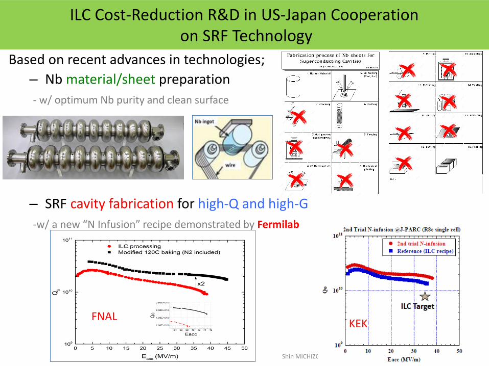
ILC Cost-Reduction R&D in US-Japan Cooperationon SRF Technology
Based on recent advances in technologies;
– Nb material/sheet preparation
- w/ optimum Nb purity and clean surface
– SRF cavity fabrication for high-Q and high-G
-w/ a new “N Infusion” recipe demonstrated by Fermilab
New potential breakthrough: very high Q at very high
gradients with low temperature (120C) nitrogen treatment
4/12/16Alexander Romanenko | FCC Week 2016 - Rome34
- Record Q at fields > 30 MV/m
- Preliminary data indicates potential 15% boost in achievable quench fields
- Can be game changer for ILC!Shin MICHIZONO, LCWS2019
43
FNALKEK
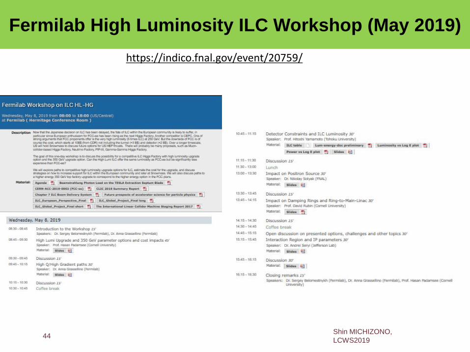
Fermilab High Luminosity ILC Workshop (May 2019)
https://indico.fnal.gov/event/20759/
Shin MICHIZONO,
LCWS201944
Fermilab High Luminosity ILC Workshop (May 2019)
Significant luminosity improvements are made possible by SRF
R&D advances since TDR
Main result is given below – by implementing technically feasible
changes, ILC baseline luminosity of 1.35 x 1034 can be
increased
– Increased number of bunches x2
– Increased rep rate x3
– Increased Q0 x 2
– Beam and IP parameters same as ILC baseline
Effective luminosity with polarization advantage (x 2.5) is
20 x 1034 cm-2s-1 (ILC) vs. 17 x 1034 cm-2s-1 (FCC-ee, including
multiplier of 2 for multiple interaction points)
AC power ~270 MW (ILC) vs. 282 MW (FCC-ee)
Details in https://arxiv.org/abs/1910.01276Shin MICHIZONO,
LCWS201945

Area Tasks
Accelerator Design Design parameter optimization
SCRF
Mass-production and quality control
Superconducting material, cavity properties (electric field, resonance
characteristics)
Hub-lab functioning
System performance stabilization
(Stabilization of the performance and maintenance, including international
transport of CM )
NanobeamMinimizing the beam size and demonstrating stability
Beam handling (DR, RTML, BDS, BD)*Accelerator elements
- Positron source (e+)
- Beam dump
e+: Undulator-driven (polarization) or an electron-driven system (backup), heat
balance of the dump, cooling, safety
CFSBasic Plan by assuming a model site, engineering design, drawings, survey,
assessment
common technical
support
Safety (radiation, high-pressure gas, etc.)
Communication and network
AdministrationGeneral affairs, finacen, int. relations, public relations
Administrative support for ILC pre-lab
Accelerator preparation phase R&Ds
46Shin MICHIZONO, LCWS2019
KEK ILC action plan
Main tasks to be done during 4-year preparation phase
47Shin MICHIZONO, LCWS2019
European ILC preparation plan

48
European ILC preparation plan
Shin MICHIZONO, LCWS2019
European Strategy input document
ILC Project Update
Shin MICHIZONOKEK/Linear Collider Collaboration (LCC)
• ILC area systems• Electron source• Positron source• Damping ring• RTML (bunch compressor)• Superconducting RF• Final focus• Beam dump• CFS
Shin MICHIZONO, LCWS2019 49
• ILC preparation (US, Japan, Europe)• Technical preparation in
“Recommendations on ILC Project”• MEXT and SCJ’s comments• Superconducting RF • Positron source• Damping ring• Final focus• Beam dump
• Summary

Recommendations on ILC Project
Shin MICHIZONO, LCWS2019 50
https://www.kek.jp/en/newsroom/2019/10/02/1000/https://www2.kek.jp/ilc/en/docs/Recommendations_on_ILC_Project_Implementation.pdf
KEK published “Recommendations on ILC Project” based on the discussion at the international WG.
Topics on ILC advisory panel’s report
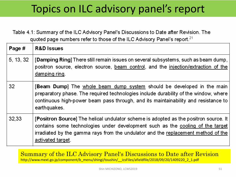
Shin MICHIZONO, LCWS2019 51
Summary of the ILC Advisory Panel's Discussions to Date after Revisionhttp://www.mext.go.jp/component/b_menu/shingi/toushin/__icsFiles/afieldfile/2018/09/20/1409220_2_1.pdf
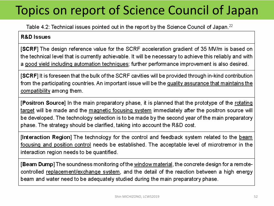
Topics on report of Science Council of Japan
Shin MICHIZONO, LCWS2019 52

Technical preparation
Shin MICHIZONO, LCWS2019 53
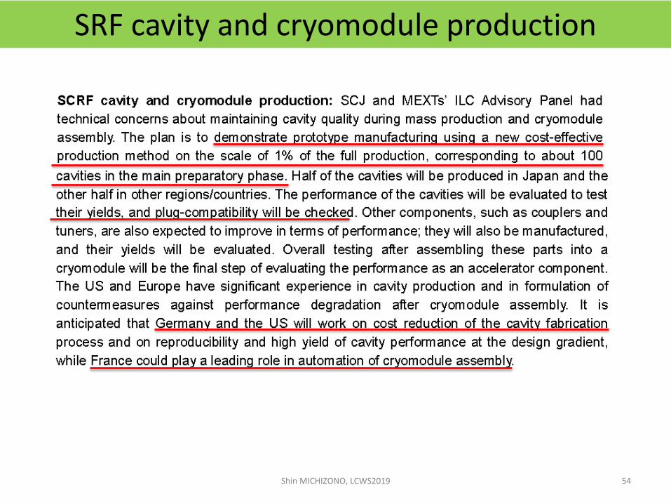
SRF cavity and cryomodule production
Shin MICHIZONO, LCWS2019 54

SRF cryomodule transport
Shin MICHIZONO, LCWS2019 55

Positron source
Shin MICHIZONO, LCWS2019 56
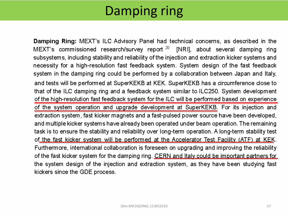
Damping ring
Shin MICHIZONO, LCWS2019 57
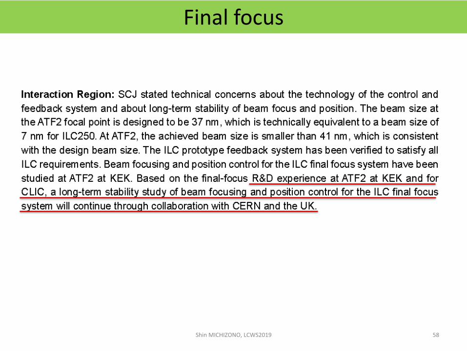
Final focus
Shin MICHIZONO, LCWS2019 58
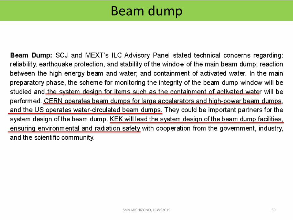
Beam dump
Shin MICHIZONO, LCWS2019 59
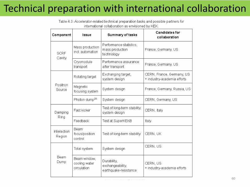
Technical preparation with international collaboration
Shin MICHIZONO, LCWS2019 60

ILC Project Update
Shin MICHIZONOKEK/Linear Collider Collaboration (LCC)
• ILC area systems• Electron source• Positron source• Damping ring• RTML (bunch compressor)• Superconducting RF• Final focus• Beam dump• CFS
Shin MICHIZONO, LCWS2019 61
• ILC preparation (US, Japan, Europe)• Technical preparation in
“Recommendations on ILC Project”• MEXT and SCJ’s comments• Superconducting RF • Positron source• Damping ring• Final focus• Beam dump
• Summary
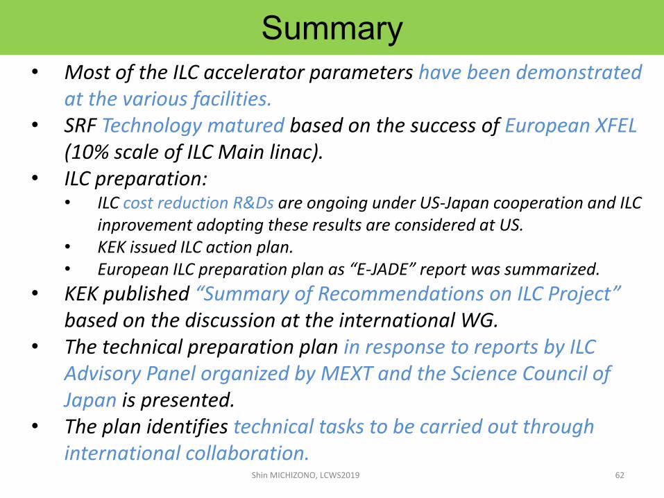
Summary
• Most of the ILC accelerator parameters have been demonstrated at the various facilities.
• SRF Technology matured based on the success of European XFEL(10% scale of ILC Main linac).
• ILC preparation: • ILC cost reduction R&Ds are ongoing under US-Japan cooperation and ILC
inprovement adopting these results are considered at US.• KEK issued ILC action plan. • European ILC preparation plan as “E-JADE” report was summarized.
• KEK published “Summary of Recommendations on ILC Project” based on the discussion at the international WG.
• The technical preparation plan in response to reports by ILC Advisory Panel organized by MEXT and the Science Council of Japan is presented.
• The plan identifies technical tasks to be carried out through international collaboration.
Shin MICHIZONO, LCWS2019 62

Thank you for your attention
Shin MICHIZONO, LCWS201963

ILC beam parameters
Shin MICHIZONO, LCWS2019 64
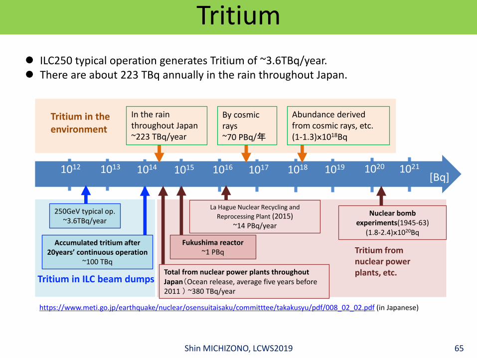
Tritium
https://www.meti.go.jp/earthquake/nuclear/osensuitaisaku/committtee/takakusyu/pdf/008_02_02.pdf (in Japanese)
ILC250 typical operation generates Tritium of ~3.6TBq/year. There are about 223 TBq annually in the rain throughout Japan.
Total from nuclear power plants throughout Japan(Ocean release, average five years before 2011 ) ~380 TBq/year
Tritium from nuclear power plants, etc.
Tritium in the environment
250GeV typical op.~3.6TBq/year
Nuclear bomb experiments(1945-63)
(1.8-2.4)x1020Bq
La Hague Nuclear Recycling and
Reprocessing Plant (2015)~14 PBq/year
Fukushima reactor~1 PBq
Tritium in ILC beam dumps
Accumulated tritium after 20years’ continuous operation
~100 TBq
In the rain throughout Japan~223 TBq/year
By cosmic rays~70 PBq/年
Abundance derived from cosmic rays, etc.(1-1.3)x1018Bq
1012
[Bq]1013 1014 1015 1016 1017 1018 1019 1020 1021
Shin MICHIZONO, LCWS2019 65
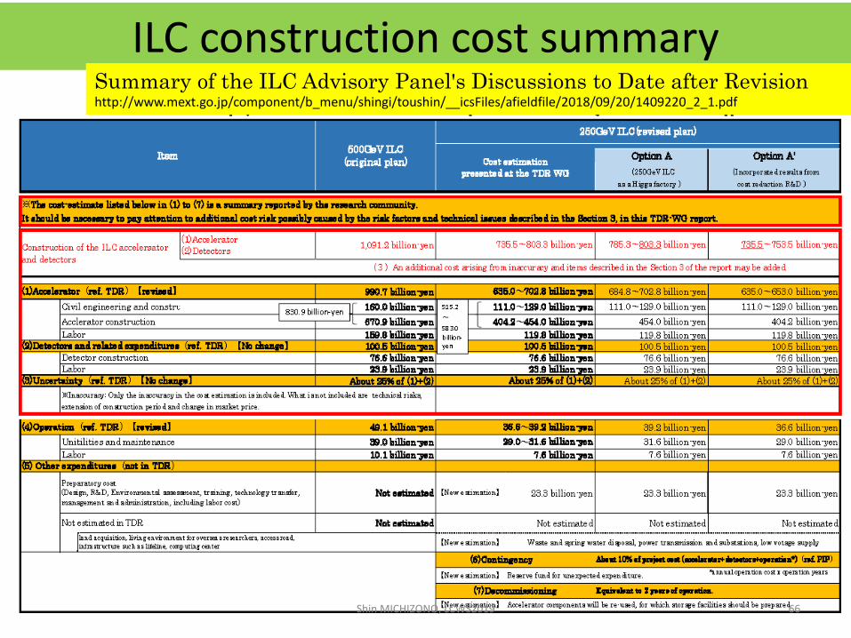
ILC construction cost summary
Shin MICHIZONO, LCWS2019 66
Summary of the ILC Advisory Panel's Discussions to Date after Revisionhttp://www.mext.go.jp/component/b_menu/shingi/toushin/__icsFiles/afieldfile/2018/09/20/1409220_2_1.pdf