Embed Size (px)
Citation preview
DSP56300 Assembly Code Development Using the Motorola Toolsets
by
Ralph Lansford
Motorola, IncorporatedSemiconductor Products Sector6501 William Cannon Drive WestAustin, TX 78735-8598
OnCE and Mfax are trademarks of Motorola, Inc.
© MOTOROLA INC., 1998
Order this document by: APR30/D
Motorola reserves the right to make changes without further notice to any products herein to improve reliability, function, or design. Motorola does not assume any liability arising out of the application or use of any product or circuit described herein; neither does it convey any license under its patent rights nor the rights of others. Motorola products are not designed, intended, or authorized for use as components in systems intended for surgical implant into the body, or other application in which the failure of the Motorola product could create a situation where personal injury or death may occur. Should Buyer purchase or use Motorola products for any such unintended or unauthorized application, Buyer shall indemnify and hold Motorola and its officers, employees, subsidiaries, affiliates, and distributors harmless against all claims, costs, damages, and expenses, and reasonable attorney fees arising out of, directly or indirectly, any claim of personal injury or death associated with such unintended or unauthorized use, even if such claim alleges that Motorola was negligent regarding the design or manufacture of the part. Motorola and are registered trademarks of Motorola, Inc. Motorola, Inc. is an Equal Opportunity/Affirmative Action Employer.
TABLE OF CONTENTS
SECTION 1 INTRODUCTION . . . . . . . . . . . . . . . . . . . . . . . . . . . . . 1-11.1 INTRODUCTION . . . . . . . . . . . . . . . . . . . . . . . . . . . . . . . . . . . . 1-31.2 TERMS AND DEFINITIONS . . . . . . . . . . . . . . . . . . . . . . . . . . . 1-31.3 SCOPE. . . . . . . . . . . . . . . . . . . . . . . . . . . . . . . . . . . . . . . . . . . . 1-4
SECTION 2 SOFTWARE DEVELOPMENT FLOW . . . . . . . . . . . . . 2-12.1 SOFTWARE DEVELOPMENT FLOW . . . . . . . . . . . . . . . . . . . . 2-32.1.1 The “make” Function . . . . . . . . . . . . . . . . . . . . . . . . . . . . . . . 2-32.1.2 Filename Conventions . . . . . . . . . . . . . . . . . . . . . . . . . . . . . . 2-32.1.3 Target Boards . . . . . . . . . . . . . . . . . . . . . . . . . . . . . . . . . . . . 2-42.2 SHARED TOOLSET RESOURCES. . . . . . . . . . . . . . . . . . . . . . 2-6
SECTION 3 SOFTWARE BUILD PROCESS . . . . . . . . . . . . . . . . . 3-13.1 INTRODUCTION . . . . . . . . . . . . . . . . . . . . . . . . . . . . . . . . . . . . 3-33.2 PROJECT MAKEFILE. . . . . . . . . . . . . . . . . . . . . . . . . . . . . . . . 3-43.2.1 UNIX Example . . . . . . . . . . . . . . . . . . . . . . . . . . . . . . . . . . . . 3-43.2.2 Porting from UNIX to DOS. . . . . . . . . . . . . . . . . . . . . . . . . . . 3-73.3 ASSEMBLY CODE FILES . . . . . . . . . . . . . . . . . . . . . . . . . . . . . 3-83.4 LINKER FILES . . . . . . . . . . . . . . . . . . . . . . . . . . . . . . . . . . . . . 3-133.5 LISTING FILES . . . . . . . . . . . . . . . . . . . . . . . . . . . . . . . . . . . . 3-153.6 EXECUTABLE FILE . . . . . . . . . . . . . . . . . . . . . . . . . . . . . . . . . 3-20
SECTION 4 USAGE OF SIMULATOR VERSUS DEBUGGER. . . . 4-14.1 OVERVIEW . . . . . . . . . . . . . . . . . . . . . . . . . . . . . . . . . . . . . . . . 4-34.2 RELATIVE ADVANTAGES . . . . . . . . . . . . . . . . . . . . . . . . . . . . 4-34.3 USER COMMAND DIFFERENCES . . . . . . . . . . . . . . . . . . . . . . 4-4
SECTION 5 HELPFUL CODING AND DEBUGGING TIPS. . . . . . . 5-15.1 ASSEMBLY CODING. . . . . . . . . . . . . . . . . . . . . . . . . . . . . . . . . 5-35.1.1 Using the One-Line Assembler . . . . . . . . . . . . . . . . . . . . . . . 5-35.1.2 Using the Help Command for Registers . . . . . . . . . . . . . . . . 5-45.2 DEBUGGING . . . . . . . . . . . . . . . . . . . . . . . . . . . . . . . . . . . . . . . 5-7
MOTOROLA DSP56300 Assembly Code Development iii

iv DSP56300 Assembly Code Development MOTOROLA
LIST OF FIGURES
Figure 2-1 Assembly Code Development Flow. . . . . . . . . . . . . . . . . . . . . . . . . . 2-5
Figure 3-1 File Hierarchy for Example Software Project. . . . . . . . . . . . . . . . . . . 3-3
Figure 3-2 makefile Components. . . . . . . . . . . . . . . . . . . . . . . . . . . . . . . . . . . . 3-6
MOTOROLA DSP56300 Assembly Code Development v
vi DSP56300 Assembly Code Development MOTOROLA
LIST OF TABLES
Table 2-1 Shared Toolset Resources . . . . . . . . . . . . . . . . . . . . . . . . . . . . . . . . 2-6
Table 4-1 Input and Output Commands: Simulator vs Debugger . . . . . . . . . . . 4-6
MOTOROLA DSP56300 Assembly Code Development vii

viii DSP56300 Assembly Code Development MOTOROLA
LIST OF EXAMPLES
Example 3-1 makefile Listing . . . . . . . . . . . . . . . . . . . . . . . . . . . . . . . . . . . . . . . . . 3-5
Example 3-2 Shell Script for Multi-File UNIX to DOS Conversion . . . . . . . . . . . . 3-7
Example 3-3 makefile Explicit Rule Syntax Comparison . . . . . . . . . . . . . . . . . . . . 3-8
Example 3-4 app1.asm . . . . . . . . . . . . . . . . . . . . . . . . . . . . . . . . . . . . . . . . . . . . . 3-9
Example 3-5 equates.asm . . . . . . . . . . . . . . . . . . . . . . . . . . . . . . . . . . . . . . . . . . 3-11
Example 3-6 Illegal Forward References with Non-Included Equates . . . . . . . . . 3-11
Example 3-7 app1_subs.asm . . . . . . . . . . . . . . . . . . . . . . . . . . . . . . . . . . . . . . . 3-12
Example 3-8 com_f1.asm . . . . . . . . . . . . . . . . . . . . . . . . . . . . . . . . . . . . . . . . . . 3-12
Example 3-9 com_f2.asm . . . . . . . . . . . . . . . . . . . . . . . . . . . . . . . . . . . . . . . . . . 3-13
Example 3-10 app1.cli . . . . . . . . . . . . . . . . . . . . . . . . . . . . . . . . . . . . . . . . . . . . . . 3-14
Example 3-11 app1.ctl . . . . . . . . . . . . . . . . . . . . . . . . . . . . . . . . . . . . . . . . . . . . . . 3-15
Example 3-12 app1.lst . . . . . . . . . . . . . . . . . . . . . . . . . . . . . . . . . . . . . . . . . . . . . . 3-16
Example 3-13 app1.map . . . . . . . . . . . . . . . . . . . . . . . . . . . . . . . . . . . . . . . . . . . . 3-18
Example 3-14 Executable Image Viewed from Simulator . . . . . . . . . . . . . . . . . . . 3-20
Example 5-1 Simulator Confirmation of Legal Instruction . . . . . . . . . . . . . . . . . . . 5-3
Example 5-2 Simulator Alert of Illegal Register . . . . . . . . . . . . . . . . . . . . . . . . . . . 5-3
Example 5-3 Simulator Alert of Illegal Addressing . . . . . . . . . . . . . . . . . . . . . . . . . 5-4
Example 5-4 Simulator Generation of Register Template . . . . . . . . . . . . . . . . . . . 5-4
Example 5-5 Register Template Saved in File . . . . . . . . . . . . . . . . . . . . . . . . . . . 5-5
MOTOROLA DSP56300 Assembly Code Development ix
Example 5-6 Simulator Output of Register Values . . . . . . . . . . . . . . . . . . . . . . . . .5-6
Example 5-7 Register Display Used in Code Comments . . . . . . . . . . . . . . . . . . . .5-6
Example 5-8 Simple Command File Pair . . . . . . . . . . . . . . . . . . . . . . . . . . . . . . . .5-7
Example 5-9 Nested Command Files . . . . . . . . . . . . . . . . . . . . . . . . . . . . . . . . . . .5-7
x DSP56300 Assembly Code Development MOTOROLA
SECTION 1
INTRODUCTION
Introduction
1.1 INTRODUCTION . . . . . . . . . . . . . . . . . . . . . . . . . . . . . . . . . . . . .1-31.2 TERMS AND DEFINITIONS . . . . . . . . . . . . . . . . . . . . . . . . . . . .1-31.3 SCOPE . . . . . . . . . . . . . . . . . . . . . . . . . . . . . . . . . . . . . . . . . . . .1-4
1-2 DSP56300 Assembly Code Development MOTOROLA
Introduction
Introduction
1.1 INTRODUCTION
The purpose of this application report is to provide integrated supplementary information for the Motorola assembly code toolsets used for the Motorola DSP56300 family of Digital Signal Processors (DSPs). It covers various aspects of the DSP56300 Assembler, Linker, Simulator, and debugger. A detailed example is supplied for management of multifile assembly code projects in the UNIX environment. Overview-level information concerning the Simulator and the Application Development System (ADS) is related, along with helpful tips for facilitating software development that will be especially beneficial to users new to the toolset.
It is assumed that the reader already has the user’s manuals for the Motorola DSP56300 Assembler, Linker, Simulator, and debugger. These may be found on the Motorola DSP World Wide Web site, beginning at the following address:
http://www.motorola-dsp.com/documentation
Note: The example code presented in this application report may be downloaded from the Motorola DSP website at the following address:
http://www.motorola-dsp.com/documentation/appnotes
1.2 TERMS AND DEFINITIONS
A number of tools are described in this document and represented by acronyms. The following list provides a reference point for the four terms most crucial to the reader’s understanding of the processes under examination.
• ADM—Application Development Modules. This is the DSP evaluation board in the ADS. The ADM generally does not contain analog/digital conversion hardware.
• ADS—Application Development System. This is a multiboard DSP development system consisting of a host card (available for several platforms), a Command Converter (universal for all platforms and all Motorola DSPs), an ADM, and the Motorola debugger (in both text-based and Graphical User Interface versions). As opposed to an Evaluation Module system, ADS versions are available for several platforms, but the ADS generally does not include analog/digital conversion hardware.
• CLAS—Callable modules Linker relocatable Assembler and Simulator. This includes the Assembler, Linker, Simulator (in both text-based and Graphical User Interface versions), librarian, lint, and various object file format conversion utilities.
MOTOROLA DSP56300 Assembly Code Development 1-3
Introduction
Scope
C source code is included, allowing the user to integrate these tools into customer-designed tools by using the callable modules, which the Linker may then link into an executable object file.
• DSP563xxEVM—Evaluation Module. This is a single board, generally including a codec (analog/digital converter). It comprises the hardware portion of a low-cost DSP evaluation system that employs an IBM-compatible PC as the development host. The Domain debugger is the software portion of the evaluation module system.
1.3 SCOPE
This document addresses the use of the following software tools:
• UNIX and DOS-based “make” utilities
• From “CLAS” package:
– Motorola DSP56300 Assembler (asm56300)
– Motorola DSP Linker (dsplnk)
– Motorola DSP56300 Simulator (sim56300/gui56300)
• From “ADS” package:
– Motorola DSP56300 debugger (ads56300/gds56300)
This document does NOT address the use of the following software tools:
• C Compilers (e.g., Motorola “g563c”)
• Domain debugger (for Evaluation Modules; runs only on IBM PC-compatible computer)
Note: The Domain debugger implements the same features as the Motorola debugger but uses a somewhat different interface.
1-4 DSP56300 Assembly Code Development MOTOROLA
SECTION 2
SOFTWARE DEVELOPMENT FLOW
Software Development Flow
2.1 SOFTWARE DEVELOPMENT FLOW. . . . . . . . . . . . . . . . . . . . .2-32.1.1 The “make” Function. . . . . . . . . . . . . . . . . . . . . . . . . . . . . . . .2-32.1.2 Filename Conventions . . . . . . . . . . . . . . . . . . . . . . . . . . . . . .2-32.1.3 Target Boards . . . . . . . . . . . . . . . . . . . . . . . . . . . . . . . . . . . . .2-42.2 SHARED TOOLSET RESOURCES . . . . . . . . . . . . . . . . . . . . . .2-6
2-2 DSP56300 Assembly Code Development MOTOROLA
Software Development Flow
Software Development Flow
2.1 SOFTWARE DEVELOPMENT FLOW
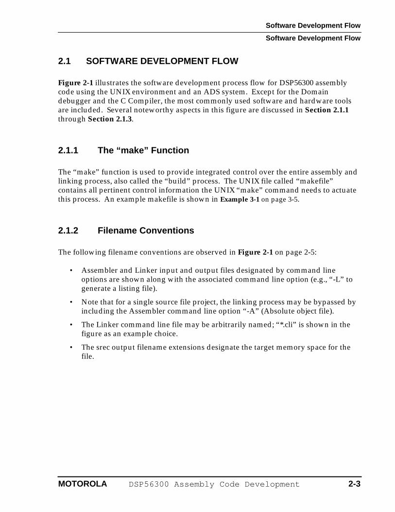
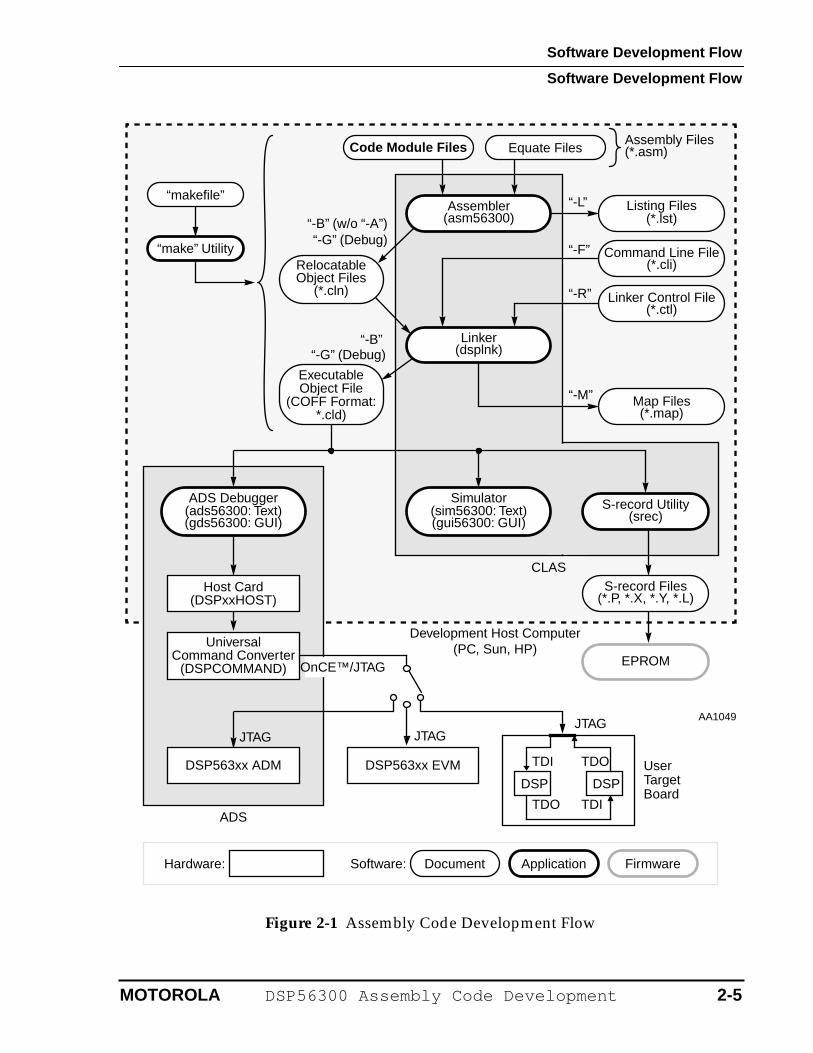
Figure 2-1 illustrates the software development process flow for DSP56300 assembly code using the UNIX environment and an ADS system. Except for the Domain debugger and the C Compiler, the most commonly used software and hardware tools are included. Several noteworthy aspects in this figure are discussed in Section 2.1.1 through Section 2.1.3.
2.1.1 The “make” Function
The “make” function is used to provide integrated control over the entire assembly and linking process, also called the “build” process. The UNIX file called “makefile” contains all pertinent control information the UNIX “make” command needs to actuate this process. An example makefile is shown in Example 3-1 on page 3-5.
2.1.2 Filename Conventions
The following filename conventions are observed in Figure 2-1 on page 2-5:
• Assembler and Linker input and output files designated by command line options are shown along with the associated command line option (e.g., “-L” to generate a listing file).
• Note that for a single source file project, the linking process may be bypassed by including the Assembler command line option “-A” (Absolute object file).
• The Linker command line file may be arbitrarily named; “*.cli” is shown in the figure as an example choice.
• The srec output filename extensions designate the target memory space for the file.
MOTOROLA DSP56300 Assembly Code Development 2-3
Software Development Flow
Software Development Flow
2.1.3 Target Boards
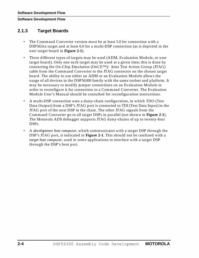
• The Command Converter version must be at least 5.0 for connection with a DSP563xx target and at least 6.0 for a multi-DSP connection (as is depicted in the user target board in Figure 2-1).
• Three different types of targets may be used (ADM, Evaluation Module, or user target board). Only one such target may be used at a given time; this is done by connecting the On-Chip Emulation (OnCE™)/ Joint Test Action Group (JTAG) cable from the Command Converter to the JTAG connector on the chosen target board. The ability to use either an ADM or an Evaluation Module allows the usage of all devices in the DSP56300 family with the same toolset and platform. It may be necessary to modify jumper connections on an Evaluation Module in order to reconfigure it for connection to a Command Converter. The Evaluation Module User’s Manual should be consulted for reconfiguration instructions.
• A multi-DSP connection uses a daisy-chain configuration, in which TDO (Test Data Output) from a DSP’s JTAG port is connected to TDI (Test Data Input) in the JTAG port of the next DSP in the chain. The other JTAG signals from the Command Converter go to all target DSPs in parallel (not shown in Figure 2-1). The Motorola ADS debugger supports JTAG daisy-chains of up to twenty-four DSPs.
• A development host computer, which communicates with a target DSP through the DSP’s JTAG port, is indicated in Figure 2-1. This should not be confused with a target host computer, used in some applications to interface with a target DSP through the DSP’s host port.
2-4 DSP56300 Assembly Code Development MOTOROLA
Software Development Flow
Software Development Flow
Figure 2-1 Assembly Code Development Flow
Code Module Files Equate FilesAssembly Files
Assembler(asm56300)
Map Files
(*.asm)
“-L”
“-B” (w/o “-A”)“-G” (Debug)
Relocatable
Linker(dsplnk)
(*.map)
Executable
ADS Debugger(ads56300: Text)(gds56300: GUI)
Linker Control File(*.ctl)
Command Line File(*.cli)
“-M”
“-B” “-G” (Debug)
“-F”
“-R”
“makefile”
“make” Utility
S-record Files(*.P, *.X, *.Y, *.L)
EPROM
Host Card(DSPxxHOST)
Universal
Hardware:
DSP563xx EVM UserDSPDSP
TDI
TDI
TDO
TDO
JTAGJTAGJTAG
Object Files(*.cln)
Object File(COFF Format:
*.cld)
Application
TargetBoard
Development Host Computer(PC, Sun, HP)
OnCE™/JTAGCommand Converter
(DSPCOMMAND)
Document FirmwareSoftware:
CLAS
Simulator(sim56300: Text)(gui56300: GUI)
S-record Utility(srec)
DSP563xx ADM
ADS
Listing Files(*.lst)
AA1049
MOTOROLA DSP56300 Assembly Code Development 2-5

Software Development Flow
Shared Toolset Resources
2.2 SHARED TOOLSET RESOURCES
Table 2-1 shows how software and hardware tools are shared among various DSP device types. Examples of Motorola DSP families are the DSP56000, DSP56300, and DSP56600 families.
Table 2-1 Shared Toolset Resources
Tool Applicability Software Tools Hardware Tools
For all DSPs Linker, utilities host card, Command Converter
Per DSP family Assembler, Simulator, ADS debugger
(n/a)
Per DSP device (n/a) ADM, Evaluation Module
2-6 DSP56300 Assembly Code Development MOTOROLA
SECTION 3
SOFTWARE BUILD PROCESS
Software Build Process
3.1 INTRODUCTION . . . . . . . . . . . . . . . . . . . . . . . . . . . . . . . . . . . . .3-33.2 PROJECT MAKEFILE . . . . . . . . . . . . . . . . . . . . . . . . . . . . . . . . .3-43.2.1 UNIX Example. . . . . . . . . . . . . . . . . . . . . . . . . . . . . . . . . . . . .3-43.2.2 Porting from UNIX to DOS . . . . . . . . . . . . . . . . . . . . . . . . . . .3-73.3 ASSEMBLY CODE FILES. . . . . . . . . . . . . . . . . . . . . . . . . . . . . .3-83.4 LINKER FILES. . . . . . . . . . . . . . . . . . . . . . . . . . . . . . . . . . . . . .3-133.5 LISTING FILES . . . . . . . . . . . . . . . . . . . . . . . . . . . . . . . . . . . . .3-153.6 EXECUTABLE FILE . . . . . . . . . . . . . . . . . . . . . . . . . . . . . . . . .3-20
3-2 DSP56300 Assembly Code Development MOTOROLA
Software Build Process
Introduction
3.1 INTRODUCTION
In this section an example software project is used to illustrate the build process (assembly and linking) outlined in the previous section. The sample files have been written to demonstrate key concepts while remaining as simple and short as possible. This section uses italics for files and boldface for commands.
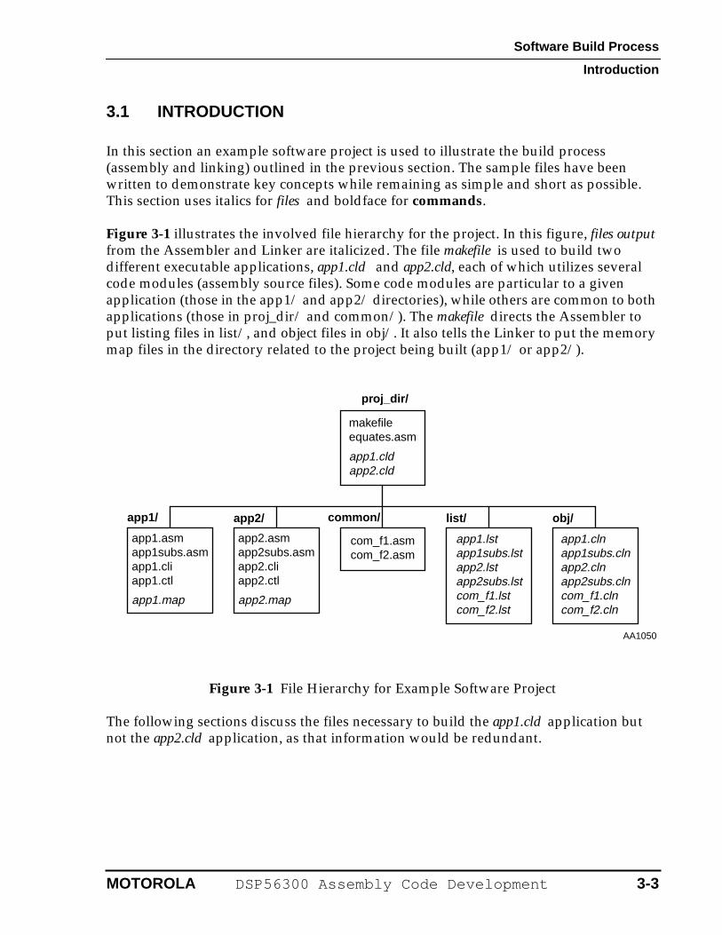
Figure 3-1 illustrates the involved file hierarchy for the project. In this figure, files output from the Assembler and Linker are italicized. The file makefile is used to build two different executable applications, app1.cld and app2.cld, each of which utilizes several code modules (assembly source files). Some code modules are particular to a given application (those in the app1/ and app2/ directories), while others are common to both applications (those in proj_dir/ and common/). The makefile directs the Assembler to put listing files in list/, and object files in obj/. It also tells the Linker to put the memory map files in the directory related to the project being built (app1/ or app2/).
Figure 3-1 File Hierarchy for Example Software Project
The following sections discuss the files necessary to build the app1.cld application but not the app2.cld application, as that information would be redundant.
makefile
app1.cldapp2.cld
app1.asmapp1subs.asmapp1.cliapp1.ctl
app1.map
com_f1.asmcom_f2.asm
app1.clnapp1subs.clnapp2.clnapp2subs.clncom_f1.clncom_f2.cln
app1.lstapp1subs.lstapp2.lstapp2subs.lstcom_f1.lstcom_f2.lst
app2.asmapp2subs.asmapp2.cliapp2.ctl
app2.map
equates.asm
proj_dir/
obj/app2/ common/app1/ list/
AA1050
MOTOROLA DSP56300 Assembly Code Development 3-3
Software Build Process
Project makefile
3.2 PROJECT MAKEFILE
Subsections of Section 3.2 explain both the use of makefile in the Sun UNIX environment and the means by which it can be ported to DOS for IBM-compatible PC use.
3.2.1 UNIX Example
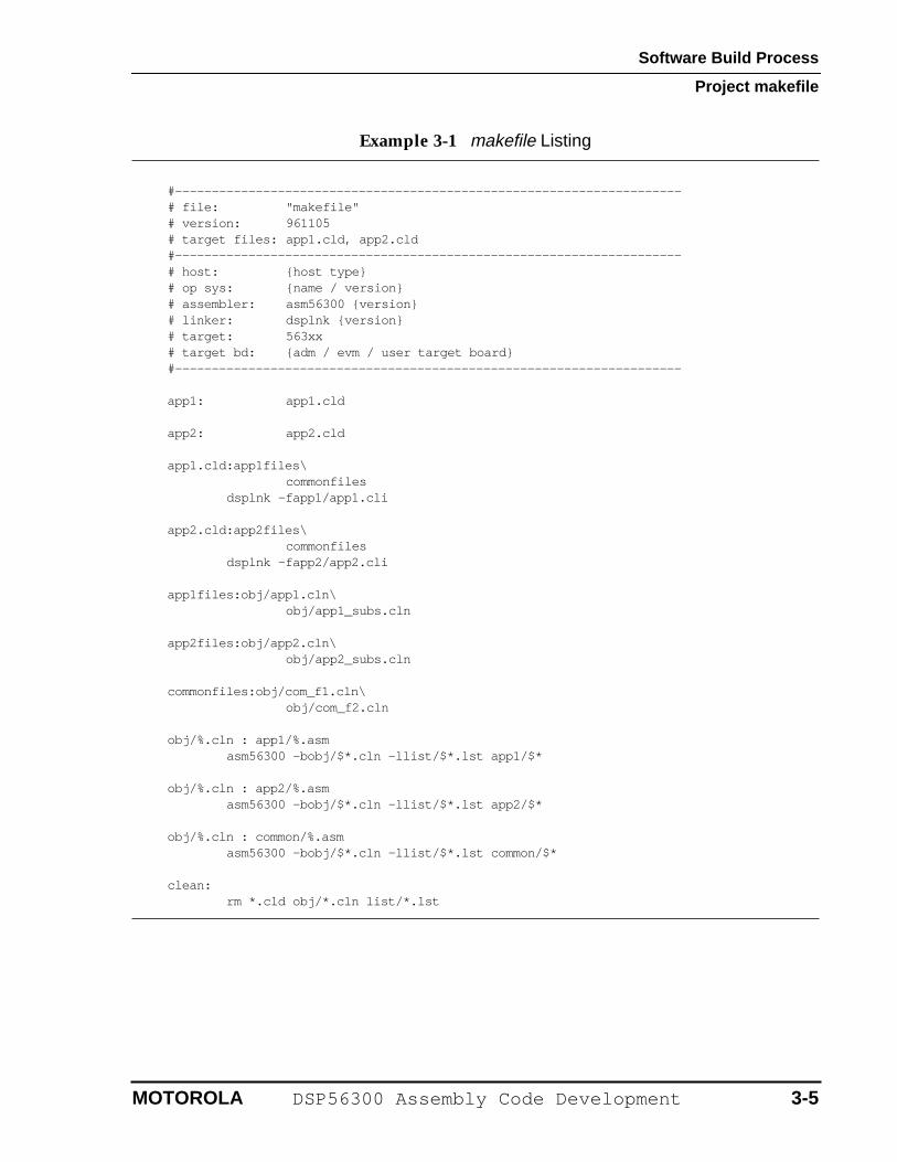
A listing of the makefile, which runs under the SUN implementation of the UNIX make command, is contained in Example 3-1. The mechanics of the makefile are covered in Figure 3-2 on page 3-6. The applications app1.cld and app2.cld are created from the UNIX command line prompt by making proj_dir/ the working directory and then typing make app1 or make app2, respectively. The cleanup option can be invoked with make clean in order to remove the Assembler output files. This is useful when a rebuild is desired to use dependency files that have not been changed since the previous build of the same application. All path specifications in the makefile are relative to the directory containing the makefile.
3-4 DSP56300 Assembly Code Development MOTOROLA
Software Build Process
Project makefile
Example 3-1 makefile Listing
#--------------------------------------------------------------------- # file: "makefile" # version: 961105# target files: app1.cld, app2.cld#--------------------------------------------------------------------- # host: {host type}# op sys: {name / version}# assembler: asm56300 {version}# linker: dsplnk {version}# target: 563xx# target bd: {adm / evm / user target board}#---------------------------------------------------------------------
app1: app1.cld
app2: app2.cld
app1.cld:app1files\ commonfiles
dsplnk -fapp1/app1.cli
app2.cld:app2files\commonfiles
dsplnk -fapp2/app2.cli
app1files:obj/app1.cln\obj/app1_subs.cln
app2files:obj/app2.cln\obj/app2_subs.cln
commonfiles:obj/com_f1.cln\obj/com_f2.cln
obj/%.cln : app1/%.asmasm56300 -bobj/$*.cln -llist/$*.lst app1/$*
obj/%.cln : app2/%.asmasm56300 -bobj/$*.cln -llist/$*.lst app2/$*
obj/%.cln : common/%.asmasm56300 -bobj/$*.cln -llist/$*.lst common/$*
clean:rm *.cld obj/*.cln list/*.lst
MOTOROLA DSP56300 Assembly Code Development 3-5
Software Build Process
Project makefile
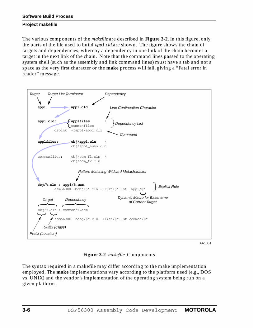
The various components of the makefile are described in Figure 3-2. In this figure, only the parts of the file used to build app1.cld are shown. The figure shows the chain of targets and dependencies, whereby a dependency in one link of the chain becomes a target in the next link of the chain. Note that the command lines passed to the operating system shell (such as the assembly and link command lines) must have a tab and not a space as the very first character or the make process will fail, giving a “Fatal error in reader” message.
Figure 3-2 makefile Components
The syntax required in a makefile may differ according to the make implementation employed. The make implementations vary according to the platform used (e.g., DOS vs. UNIX) and the vendor’s implementation of the operating system being run on a given platform.
Target
Dependency List
Line Continuation Character
Dynamic Macro for BasenameTarget Dependency
Command
Target List Terminator
Pattern Matching Wildcard Metacharacter
of Current Target
Prefix (Location)
Suffix (Class)
obj/%.cln : common/%.asm
asm56300 -bobj/$*.cln -llist/$*.lst common/$*
commonfiles: obj/com_f1.cln \obj/com_f2.cln
Explicit Rule
app1files: obj/app1.cln \obj/app1_subs.cln
app1.cld: app1files \commonfiles
dsplnk -fapp1/app1.cli
app1: app1.cld
Dependency
AA1051
obj/%.cln : app1/%.asmapp1/$*asm56300 -bobj/$*.cln -llist/$*.lst
3-6 DSP56300 Assembly Code Development MOTOROLA
Software Build Process
Project makefile
In the UNIX environment, additional information on the makefile and the make command may be obtained from the on-line manual pages (man make at the UNIX prompt).
3.2.2 Porting from UNIX to DOS
If the project is being used in the DOS environment, the following changes must be made:
1. Change all directory and filenames to legal DOS names and use “\” instead of “/” to denote directories. This would apply to the files themselves and to the file references in the makefile.
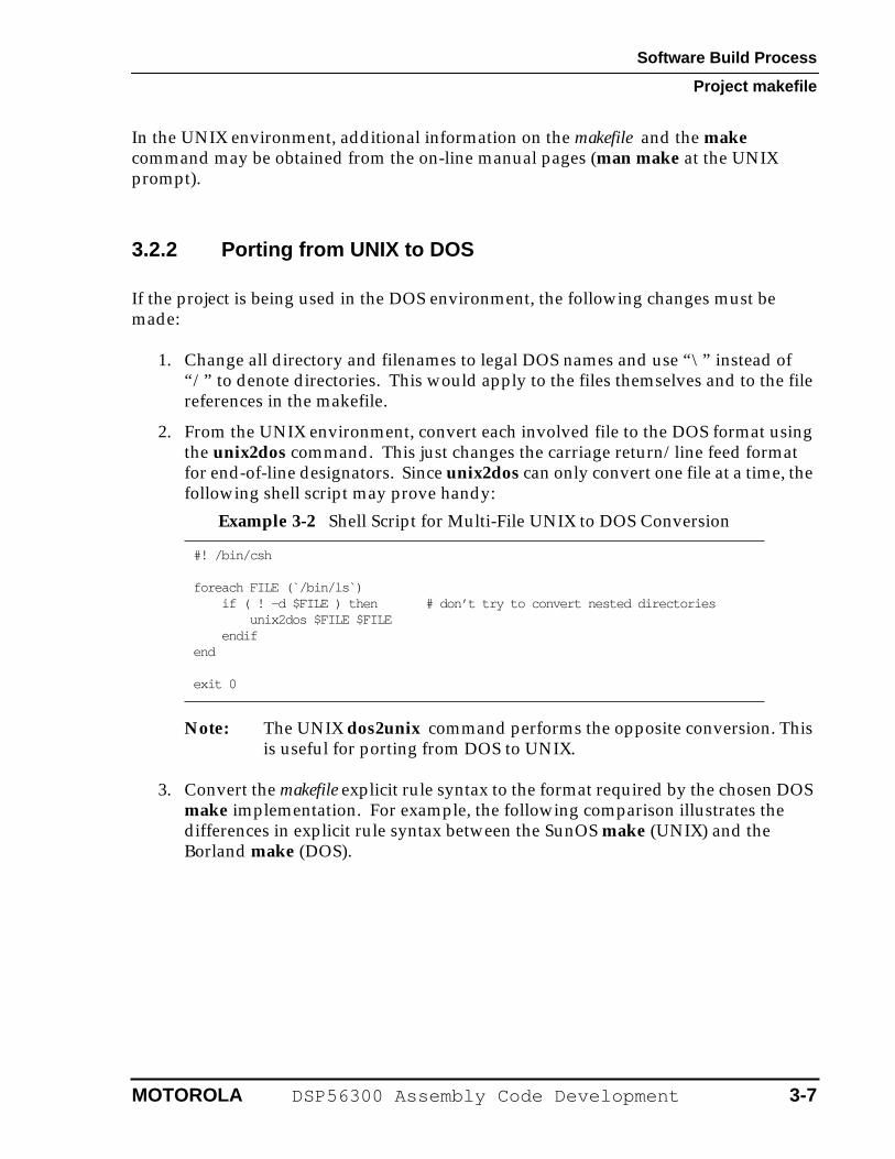
2. From the UNIX environment, convert each involved file to the DOS format using the unix2dos command. This just changes the carriage return/line feed format for end-of-line designators. Since unix2dos can only convert one file at a time, the following shell script may prove handy:
Note: The UNIX dos2unix command performs the opposite conversion. This is useful for porting from DOS to UNIX.
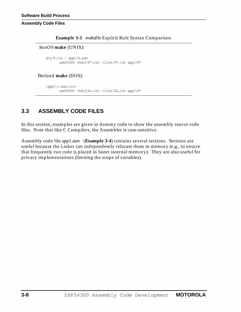
3. Convert the makefile explicit rule syntax to the format required by the chosen DOS make implementation. For example, the following comparison illustrates the differences in explicit rule syntax between the SunOS make (UNIX) and the Borland make (DOS).
Example 3-2 Shell Script for Multi-File UNIX to DOS Conversion
#! /bin/csh
foreach FILE (̀ /bin/ls̀ ) if ( ! -d $FILE ) then # don’t try to convert nested directories unix2dos $FILE $FILE endifend
exit 0
MOTOROLA DSP56300 Assembly Code Development 3-7
Software Build Process
Assembly Code Files
3.3 ASSEMBLY CODE FILES
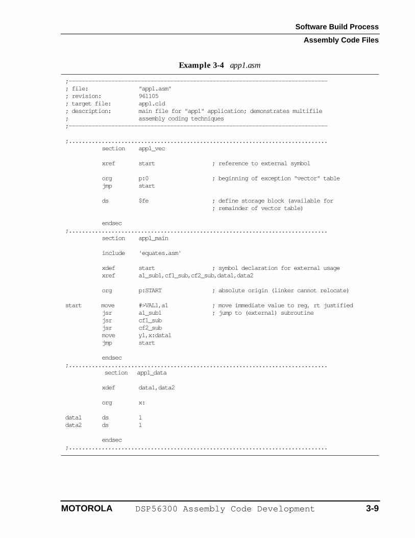
In this section, examples are given in dummy code to show the assembly source code files. Note that like C Compilers, the Assembler is case-sensitive.
Assembly code file app1.asm (Example 3-4) contains several sections. Sections are useful because the Linker can independently relocate them in memory (e.g., to ensure that frequently run code is placed in faster internal memory). They are also useful for privacy implementations (limiting the scope of variables).
Example 3-3 makefile Explicit Rule Syntax Comparison
SunOS make (UNIX):
obj/%.cln : app1/%.asmasm56300 -bobj/$*.cln -llist/$*.lst app1/$*
Borland make (DOS):
{app1\}.asm.cln:asm56300 -bobj\$&.cln -llist\$&.lst app1\$*
3-8 DSP56300 Assembly Code Development MOTOROLA
Software Build Process
Assembly Code Files
Example 3-4 app1.asm
;------------------------------------------------------------------------------- ; file: "app1.asm"; revision: 961105; target file: app1.cld; description: main file for "app1" application; demonstrates multifile; assembly coding techniques;-------------------------------------------------------------------------------
;...............................................................................section app1_vec
xref start ; reference to external symbol
org p:0 ; beginning of exception "vector" table jmp start
ds $fe ; define storage block (available for ; remainder of vector table)
endsec;...............................................................................
section app1_main
include 'equates.asm'
xdef start ; symbol declaration for external usagexref a1_sub1,cf1_sub,cf2_sub,data1,data2
org p:START ; absolute origin (linker cannot relocate) start move #>VAL1,a1 ; move immediate value to reg, rt justified
jsr a1_sub1 ; jump to (external) subroutinejsr cf1_subjsr cf2_submove y1,x:data1jmp start
endsec;............................................................................... section app1_data
xdef data1,data2
org x: data1 ds 1data2 ds 1
endsec;...............................................................................
MOTOROLA DSP56300 Assembly Code Development 3-9
Software Build Process
Assembly Code Files
Relocatable portions of code or data may be designated by using an indefinite origin for a given memory space (such as “x:”). The first such portion in a given assembly source file will be mapped beginning at location zero in the specified memory space in the relocatable image that the Assembler produces. The Linker may relocate this portion of the code or data to a new address in the executable image. The relocation may be seen by comparing the *.lst and *.map files.
Privacy limitations may be imposed on symbols (which are memory locations or values, such as equates). Symbols defined within a section are not normally visible outside that section. The Assembler directive xdef is used inside a “source” section to define the symbol for use in another section (the “destination” section). The xref directive is used inside the “destination” section to reference symbols defined using xdef in the “source” section. These two sections may or may not be in the same file.
An alternate method is to declare a symbol as a global inside a section or to define the symbol outside any section. This results in a globally defined symbol that can be referenced from other sections without using xref. More detailed information on this and related subjects may be found in the Software Project Management section in the Motorola DSP Assembler Reference Manual.
In a section, externally defined symbols result in “holes” in the relocatable image file generated by the Assembler. These “holes” are unresolved external references. The Linker must then “plug” the holes by resolving the references.
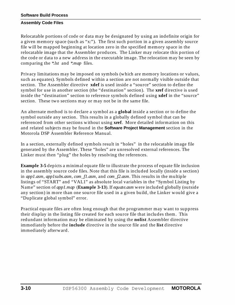
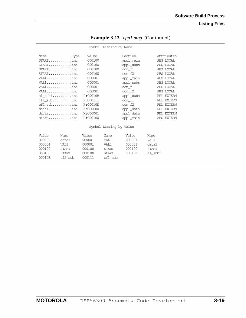
Example 3-5 depicts a minimal equate file to illustrate the process of equate file inclusion in the assembly source code files. Note that this file is included locally (inside a section) in app1.asm, app1subs.asm, com_f1.asm, and com_f2.asm. This results in the multiple listings of “START” and “VAL1” as absolute local variables in the “Symbol Listing by Name” section of app1.map (Example 3-13). If equate.asm were included globally (outside any section) in more than one source file used in a given build, the Linker would give a “Duplicate global symbol” error.
Practical equate files are often long enough that the programmer may want to suppress their display in the listing file created for each source file that includes them. This redundant information may be eliminated by using the nolist Assembler directive immediately before the include directive in the source file and the list directive immediately afterward.
3-10 DSP56300 Assembly Code Development MOTOROLA
Software Build Process
Assembly Code Files
An alternate way of using an equate file is to explicitly specify it in the build process (in makefile ) rather than including it in each source file that uses it. The result is assembly of the equate file into a separate relocatable image file (*.cln ). This could be referred to as the “discrete equate file method”, as opposed to the “included equate file method” previously described.
This method has the advantage of equate file inclusion in the dependency process. If the equate file is edited, a succeeding build will automatically cause any files dependent on it to be reassembled and relinked (for the application being rebuilt).
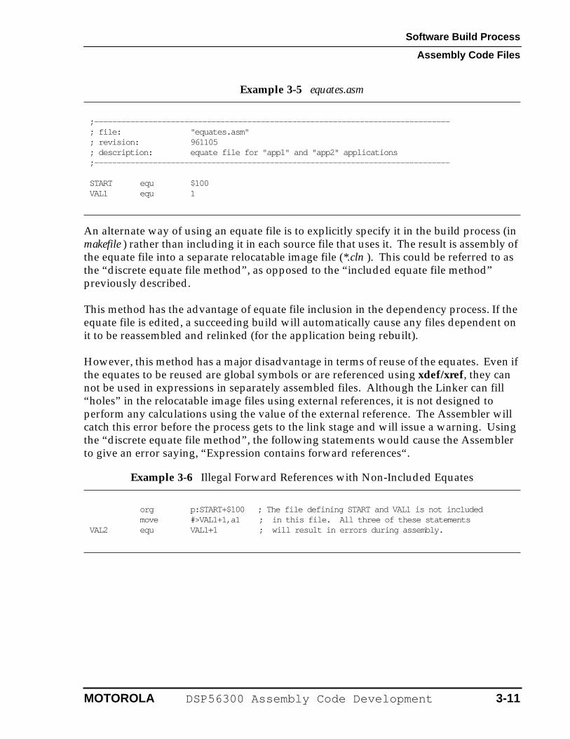
However, this method has a major disadvantage in terms of reuse of the equates. Even if the equates to be reused are global symbols or are referenced using xdef/xref, they can not be used in expressions in separately assembled files. Although the Linker can fill “holes” in the relocatable image files using external references, it is not designed to perform any calculations using the value of the external reference. The Assembler will catch this error before the process gets to the link stage and will issue a warning. Using the “discrete equate file method”, the following statements would cause the Assembler to give an error saying, “Expression contains forward references“.
Example 3-5 equates.asm
;------------------------------------------------------------------------------- ; file: "equates.asm"; revision: 961105; description: equate file for "app1" and "app2" applications;-------------------------------------------------------------------------------
START equ $100VAL1 equ 1
Example 3-6 Illegal Forward References with Non-Included Equates
org p:START+$100 ; The file defining START and VAL1 is not included move #>VAL1+1,a1 ; in this file. All three of these statementsVAL2 equ VAL1+1 ; will result in errors during assembly.
MOTOROLA DSP56300 Assembly Code Development 3-11
Software Build Process
Assembly Code Files
c
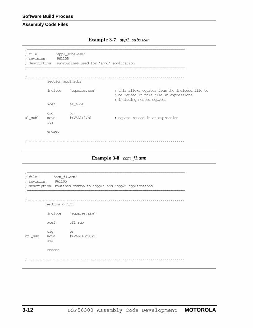
Example 3-7 app1_subs.asm
;------------------------------------------------------------------------------- ; file: "app1_subs.asm"; revision: 961105; description: subroutines used for "app1" application;-------------------------------------------------------------------------------
;...............................................................................section app1_subs
include 'equates.asm' ; this allows equates from the included file to ; be reused in this file in expressions, ; including nested equates
xdef a1_sub1
org p: a1_sub1 move #>VAL1+1,b1 ; equate reused in an expression
rts
endsec
;...............................................................................
Example 3-8 com_f1.asm
;------------------------------------------------------------------------------- ; file: "com_f1.asm"; revision: 961105; description: routines common to "app1" and "app2" applications;-------------------------------------------------------------------------------
;............................................................................... section com_f1
include 'equates.asm'
xdef cf1_sub
org p: cf1_sub move #>VAL1+$c0,x1
rts
endsec
;...............................................................................
3-12 DSP56300 Assembly Code Development MOTOROLA
Software Build Process
Linker Files
3.4 LINKER FILES
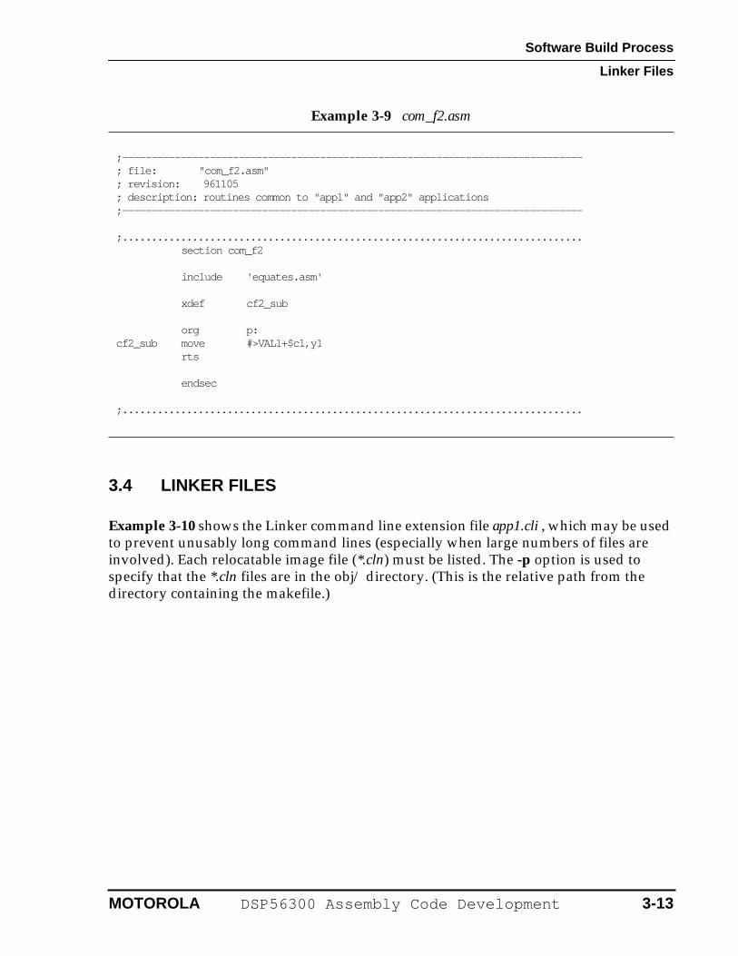
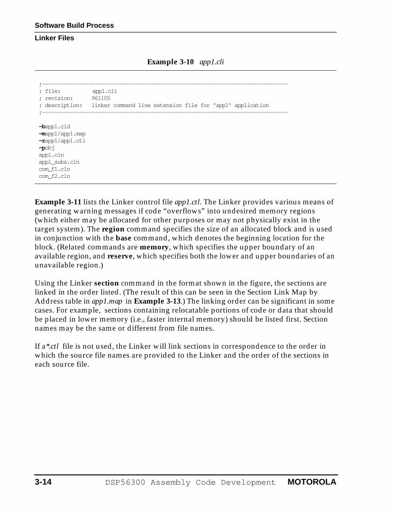
Example 3-10 shows the Linker command line extension file app1.cli , which may be used to prevent unusably long command lines (especially when large numbers of files are involved). Each relocatable image file (*.cln) must be listed. The -p option is used to specify that the *.cln files are in the obj/ directory. (This is the relative path from the directory containing the makefile.)
Example 3-9 com_f2.asm
;------------------------------------------------------------------------------- ; file: "com_f2.asm"; revision: 961105; description: routines common to "app1" and "app2" applications;-------------------------------------------------------------------------------
;...............................................................................section com_f2
include 'equates.asm'
xdef cf2_sub
org p: cf2_sub move #>VAL1+$c1,y1
rts
endsec
;...............................................................................
MOTOROLA DSP56300 Assembly Code Development 3-13
Software Build Process
Linker Files
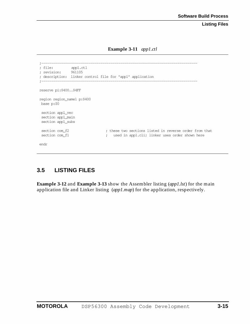
Example 3-11 lists the Linker control file app1.ctl. The Linker provides various means of generating warning messages if code “overflows” into undesired memory regions (which either may be allocated for other purposes or may not physically exist in the target system). The region command specifies the size of an allocated block and is used in conjunction with the base command, which denotes the beginning location for the block. (Related commands are memory, which specifies the upper boundary of an available region, and reserve, which specifies both the lower and upper boundaries of an unavailable region.)
Using the Linker section command in the format shown in the figure, the sections are linked in the order listed. (The result of this can be seen in the Section Link Map by Address table in app1.map in Example 3-13.) The linking order can be significant in some cases. For example, sections containing relocatable portions of code or data that should be placed in lower memory (i.e., faster internal memory) should be listed first. Section names may be the same or different from file names.
If a*.ctl file is not used, the Linker will link sections in correspondence to the order in which the source file names are provided to the Linker and the order of the sections in each source file.
Example 3-10 app1.cli
;------------------------------------------------------------------------------- ; file: app1.cli; revision: 961105; description: linker command line extension file for "app1" application;-------------------------------------------------------------------------------
-b app1.cld-mapp1/app1.map-r app1/app1.ctl-p objapp1.clnapp1_subs.clncom_f1.clncom_f2.cln
3-14 DSP56300 Assembly Code Development MOTOROLA
Software Build Process
Listing Files
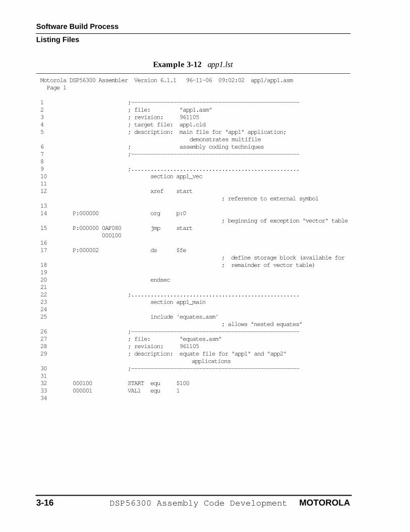
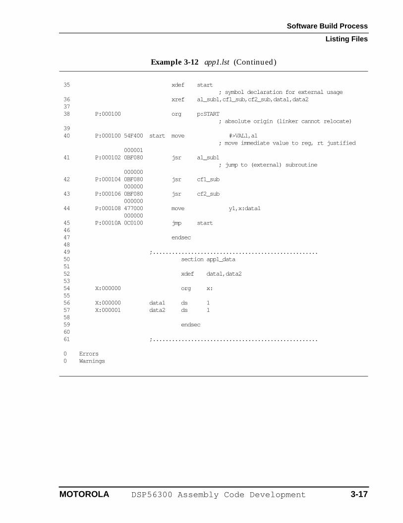
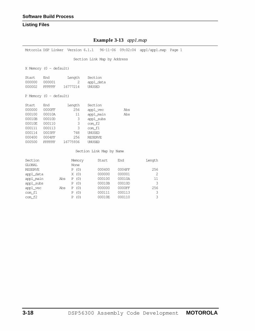
3.5 LISTING FILES
Example 3-12 and Example 3-13 show the Assembler listing (app1.lst) for the main application file and Linker listing (app1.map) for the application, respectively.
Example 3-11 app1.ctl
;------------------------------------------------------------------------------- ; file: app1.ctl; revision: 961105; description: linker control file for "app1" application;-------------------------------------------------------------------------------
reserve pi:$400..$4FF
region region_name1 p:$400 base p:$0
section app1_vec section app1_main section app1_subs
section com_f2 ; these two sections listed in reverse order from that section com_f1 ; used in app1.cli; linker uses order shown here
endr
MOTOROLA DSP56300 Assembly Code Development 3-15
Software Build Process
Listing Files
Example 3-12 app1.lst
Motorola DSP56300 Assembler Version 6.1.1 96-11-06 09:02:02 app1/app1.asm Page 1
1 ;----------------------------------------------------2 ; file: "app1.asm"3 ; revision: 9611054 ; target file: app1.cld5 ; description: main file for "app1" application;
demonstrates multifile6 ; assembly coding techniques7 ;----------------------------------------------------8 9 ;....................................................10 section app1_vec11 12 xref start
; reference to external symbol13 14 P:000000 org p:0
; beginning of exception "vector" table15 P:000000 0AF080 jmp start 00010016 17 P:000002 ds $fe
; define storage block (available for18 ; remainder of vector table)19 20 endsec21 22 ;....................................................23 section app1_main24 25 include 'equates.asm'
; allows "nested equates"26 ;----------------------------------------------------27 ; file: "equates.asm"28 ; revision: 96110529 ; description: equate file for "app1" and "app2"
applications30 ;----------------------------------------------------31 32 000100 START equ $10033 000001 VAL1 equ 134
3-16 DSP56300 Assembly Code Development MOTOROLA
Software Build Process
Listing Files
35 xdef start ; symbol declaration for external usage
36 xref a1_sub1,cf1_sub,cf2_sub,data1,data237 38 P:000100 org p:START ; absolute origin (linker cannot relocate)39 40 P:000100 54F400 start move #>VAL1,a1 ; move immediate value to reg, rt justified 00000141 P:000102 0BF080 jsr a1_sub1 ; jump to (external) subroutine 00000042 P:000104 0BF080 jsr cf1_sub 00000043 P:000106 0BF080 jsr cf2_sub 00000044 P:000108 477000 move y1,x:data1 00000045 P:00010A 0C0100 jmp start46 47 endsec48 49 ;....................................................50 section app1_data51 52 xdef data1,data253 54 X:000000 org x:55 56 X:000000 data1 ds 157 X:000001 data2 ds 158 59 endsec60 61 ;....................................................
0 Errors0 Warnings
Example 3-12 app1.lst (Continued)
MOTOROLA DSP56300 Assembly Code Development 3-17
Software Build Process
Listing Files
Example 3-13 app1.map
Motorola DSP Linker Version 6.1.1 96-11-06 09:02:04 app1/app1.map Page 1
Section Link Map by Address
X Memory (0 - default)
Start End Length Section000000 000001 2 app1_data000002 FFFFFF 16777214 UNUSED
P Memory (0 - default)
Start End Length Section000000 0000FF 256 app1_vec Abs000100 00010A 11 app1_main Abs00010B 00010D 3 app1_subs00010E 000110 3 com_f2000111 000113 3 com_f1000114 0003FF 748 UNUSED000400 0004FF 256 RESERVE000500 FFFFFF 16775936 UNUSED
Section Link Map by Name
Section Memory Start End LengthGLOBAL NoneRESERVE P (0) 000400 0004FF 256app1_data X (0) 000000 000001 2app1_main Abs P (0) 000100 00010A 11app1_subs P (0) 00010B 00010D 3app1_vec Abs P (0) 000000 0000FF 256com_f1 P (0) 000111 000113 3com_f2 P (0) 00010E 000110 3
3-18 DSP56300 Assembly Code Development MOTOROLA
Software Build Process
Listing Files
Symbol Listing by Name
Name Type Value Section AttributesSTART............int 000100 app1_main ABS LOCALSTART............int 000100 app1_subs ABS LOCALSTART............int 000100 com_f1 ABS LOCALSTART............int 000100 com_f2 ABS LOCALVAL1.............int 000001 app1_main ABS LOCALVAL1.............int 000001 app1_subs ABS LOCALVAL1.............int 000001 com_f1 ABS LOCALVAL1.............int 000001 com_f2 ABS LOCALa1_sub1..........int P:00010B app1_subs REL EXTERNcf1_sub..........int P:000111 com_f1 REL EXTERNcf2_sub..........int P:00010E com_f2 REL EXTERNdata1............int X:000000 app1_data REL EXTERNdata2............int X:000001 app1_data REL EXTERNstart............int P:000100 app1_main ABS EXTERN
Symbol Listing by Value
Value Name Value Name Value Name000000 data1 000001 VAL1 000001 VAL1000001 VAL1 000001 VAL1 000001 data2000100 START 000100 START 000100 START000100 START 000100 start 00010B a1_sub100010E cf2_sub 000111 cf1_sub
Example 3-13 app1.map (Continued)
MOTOROLA DSP56300 Assembly Code Development 3-19
Software Build Process
Executable File
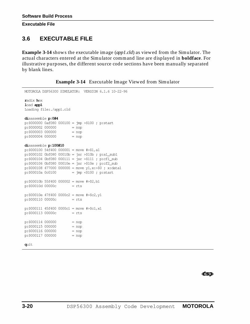
3.6 EXECUTABLE FILE
Example 3-14 shows the executable image (app1.cld) as viewed from the Simulator. The actual characters entered at the Simulator command line are displayed in boldface. For illustrative purposes, the different source code sections have been manually separated by blank lines.
Example 3-14 Executable Image Viewed from Simulator
MOTOROLA DSP56300 SIMULATOR: VERSION 6.1.6 10-22-96
r adix hexl oad app1Loading file:./app1.cld
di sassemble p:0#4p:$000000 0af080 000100 = jmp >$100 ; p:startp:$000002 000000 = nopp:$000003 000000 = nop p:$000004 000000 = nop
di sassemble p:100#10p:$000100 54f400 000001 = move #>$1,a1p:$000102 0bf080 00010b = jsr >$10b ; p:a1_sub1p:$000104 0bf080 000111 = jsr >$111 ; p:cf1_subp:$000106 0bf080 00010e = jsr >$10e ; p:cf2_subp:$000108 477000 000000 = move y1,x:>$0 ; x:data1p:$00010a 0c0100 = jmp <$100 ; p:start
p:$00010b 55f400 000002 = move #>$2,b1p:$00010d 00000c = rts
p:$00010e 47f400 0000c2 = move #>$c2,y1p:$000110 00000c = rts
p:$000111 45f400 0000c1 = move #>$c1,x1p:$000113 00000c = rts
p:$000114 000000 = nop p:$000115 000000 = nopp:$000116 000000 = nop p:$000117 000000 = nop
quit
3-20 DSP56300 Assembly Code Development MOTOROLA
SECTION 4
USAGE OF SIMULATOR VERSUS DEBUGGER
Usage of Simulator versus Debugger
4.1 OVERVIEW . . . . . . . . . . . . . . . . . . . . . . . . . . . . . . . . . . . . . . . . .4-34.2 RELATIVE ADVANTAGES . . . . . . . . . . . . . . . . . . . . . . . . . . . . .4-34.3 USER COMMAND DIFFERENCES . . . . . . . . . . . . . . . . . . . . . .4-4
4-2 DSP56300 Assembly Code Development MOTOROLA
Usage of Simulator versus Debugger
Overview
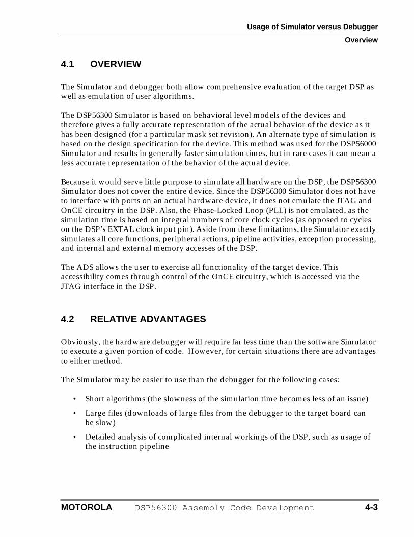
4.1 OVERVIEW
The Simulator and debugger both allow comprehensive evaluation of the target DSP as well as emulation of user algorithms.
The DSP56300 Simulator is based on behavioral level models of the devices and therefore gives a fully accurate representation of the actual behavior of the device as it has been designed (for a particular mask set revision). An alternate type of simulation is based on the design specification for the device. This method was used for the DSP56000 Simulator and results in generally faster simulation times, but in rare cases it can mean a less accurate representation of the behavior of the actual device.
Because it would serve little purpose to simulate all hardware on the DSP, the DSP56300 Simulator does not cover the entire device. Since the DSP56300 Simulator does not have to interface with ports on an actual hardware device, it does not emulate the JTAG and OnCE circuitry in the DSP. Also, the Phase-Locked Loop (PLL) is not emulated, as the simulation time is based on integral numbers of core clock cycles (as opposed to cycles on the DSP’s EXTAL clock input pin). Aside from these limitations, the Simulator exactly simulates all core functions, peripheral actions, pipeline activities, exception processing, and internal and external memory accesses of the DSP.
The ADS allows the user to exercise all functionality of the target device. This accessibility comes through control of the OnCE circuitry, which is accessed via the JTAG interface in the DSP.
4.2 RELATIVE ADVANTAGES
Obviously, the hardware debugger will require far less time than the software Simulator to execute a given portion of code. However, for certain situations there are advantages to either method.
The Simulator may be easier to use than the debugger for the following cases:
• Short algorithms (the slowness of the simulation time becomes less of an issue)
• Large files (downloads of large files from the debugger to the target board can be slow)
• Detailed analysis of complicated internal workings of the DSP, such as usage of the instruction pipeline
MOTOROLA DSP56300 Assembly Code Development 4-3
Usage of Simulator versus Debugger
User Command Differences
The ADS is necessary, or tends to be more useful, in these situations:
• DSP interfaced with external hardware that can not easily be simulated
• Timing needs investigation with a resolution smaller than single core clock cycles
• Very long algorithms (may take a prohibitively long time to simulate)
• Usage of peripherals which are running much more slowly than the core clock: the Simulator must execute every core clock cycle, regardless of the peripheral clock division.
Obviously, there are many other situations in which usage of the actual hardware is necessary (for observing voltage levels, measuring current consumption, etc.).
4.3 USER COMMAND DIFFERENCES
The commands and usage of the Simulator and debugger are designed to be as close to identical as possible. However, there are a few differences that are either related to the nature of simulation or that result from hardware that is not simulated.
• Cxxxxx and host commands—The debugger uses special commands that are dedicated to the nontarget boards comprising the ADS. The Cxxxxx commands (cchange, cdisplay, cforce, etc.) are used to perform actions on the Command Converter board. The host command is used to configure the Host board. These commands do not exist in the Simulator.
• Display command—Because they are not simulated, the Simulator does not display the registers in the PLL and JTAG/OnCE subsections of the DSP. However, the Simulator displays several count registers—for example, clock cycle and instruction count registers—that are not part of the actual DSP and are not provided by the debugger.
• Go and break commands—Due to the lack of JTAG/OnCE simulation, the Simulator handles the go and break commands differently than does the debugger. The debugger uses the break command to specify the breakpoint occurrence count (i.e., to stop on the nth occurrence) because this functionality is built into the OnCE circuitry. The Simulator uses the go command to specify the breakpoint occurrence count. This allows the user to resume execution and use a different occurrence count with a single command.
• History command—The history command displays the last 32 executed instructions along with the addresses from which they were fetched. This command is available on the Simulator but not the debugger.
4-4 DSP56300 Assembly Code Development MOTOROLA
Usage of Simulator versus Debugger
User Command Differences
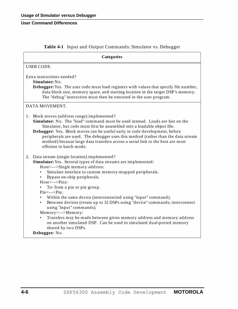
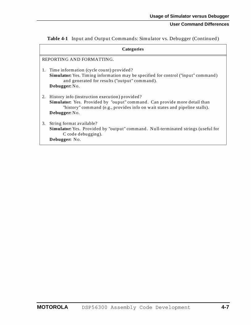
• Input and output commands—The debugger needs to use the JTAG/OnCE interface in order to transfer blocks of data between a file (or the console) in the development host computer and the target DSP’s internal or external memory. In the course of these actions, the OnCE module forces the DSP to execute instructions that actually do the reads or writes of the DSP’s memory. Because the Simulator bypasses the debug interface by not simulating it, it offers simplified input and output functions as well as features not included in the debugger. The Simulator also provides reporting and formatting functions not available in the debugger, such as instruction timing and history information. Table 4-1 compares the Simulator and debugger implementations of input and output.
• Load command—The methodology required to use the load command is subtly different in the Simulator than it is in the debugger. This issue also involves various other commands that access external memory locations.
– With the debugger, it is necessary to perform any appropriate initialization of Bus Interface Unit (BIU) registers before executing a program load that will result in writes to external memory locations (either program or data). This must be done because the OnCE module actuates downloads to memory by forcing core (specifically, Program Control Unit) writes to the designated addresses, without regard to whether the addresses are internal or external. The BIU register initialization may be done by explicitly entered debugger commands, by debugger command files, or by previously executed DSP code. Note that this must also be done before any other debugger accesses to external memory locations (display, change, etc.).
– Using the Simulator, no BIU register initialization is necessary before program loads (or before other Simulator accesses to external memory locations).
– Also note that the BIU must always be initialized before the user code attempts to access external memory locations (true whether the Simulator or debugger is used).
• Radix command—The default radix is decimal in the Simulator, but hexadecimal in the debugger. A possible way to avoid confusion is to begin commonly used Simulator command files with “radix hex”.
• Reset and force commands—Using the Simulator, the DSP being simulated is reset with the reset command, and halted by typing control-C. On the debugger, these functions are performed by using the force command—"force reset", or "force break", respectively.
MOTOROLA DSP56300 Assembly Code Development 4-5
Usage of Simulator versus Debugger
User Command Differences
Table 4-1 Input and Output Commands: Simulator vs. Debugger
Categories
USER CODE.
Extra instructions needed?Simulator: No.Debugger: Yes. The user code must load registers with values that specify file number,
data block size, memory space, and starting location in the target DSP’s memory. The "debug" instruction must then be executed in the user program.
DATA MOVEMENT.
1. Block moves (address range) implemented?Simulator: No. The "load" command must be used instead. Loads are fast on the
Simulator, but code must first be assembled into a loadable object file.Debugger: Yes. Block moves can be useful early in code development, before
peripherals are used. The debugger uses this method (rather than the data stream method) because large data transfers across a serial link to the host are most efficient in batch mode.
2. Data stream (single location) implemented?Simulator: Yes. Several types of data streams are implemented:
Host<—>Single memory address:• Simulate interface to custom memory-mapped peripherals.• Bypass on-chip peripherals.Host<—>Pins:• To/from a pin or pin group.Pin<—>Pin:• Within the same device (interconnected using "input" command).• Between devices (create up to 32 DSPs using "device" commands; interconnect
using "input" commands).Memory<—>Memory:• Transfers may be made between given memory address and memory address
on another simulated DSP. Can be used to simulated dual-ported memory shared by two DSPs.
Debugger: No.
4-6 DSP56300 Assembly Code Development MOTOROLA
Usage of Simulator versus Debugger
User Command Differences
REPORTING AND FORMATTING.
1. Time information (cycle count) provided?Simulator: Yes. Timing information may be specified for control ("input" command)
and generated for results ("output" command).Debugger: No.
2. History info (instruction execution) provided?Simulator: Yes. Provided by "ouput" command. Can provide more detail than
"history" command (e.g., provides info on wait states and pipeline stalls).Debugger: No.
3. String format available?Simulator: Yes. Provided by "output" command. Null-terminated strings (useful for
C code debugging).Debugger: No.
Table 4-1 Input and Output Commands: Simulator vs. Debugger (Continued)
Categories
MOTOROLA DSP56300 Assembly Code Development 4-7
Usage of Simulator versus Debugger
User Command Differences
4-8 DSP56300 Assembly Code Development MOTOROLA
SECTION 5
HELPFUL CODING AND DEBUGGING TIPS
Helpful Coding and Debugging Tips
5.1 ASSEMBLY CODING . . . . . . . . . . . . . . . . . . . . . . . . . . . . . . . . .5-35.1.1 Using the One-Line Assembler . . . . . . . . . . . . . . . . . . . . . . . .5-35.1.2 Using the Help Command for Registers . . . . . . . . . . . . . . . . .5-45.2 DEBUGGING. . . . . . . . . . . . . . . . . . . . . . . . . . . . . . . . . . . . . . . .5-7
5-2 DSP56300 Assembly Code Development MOTOROLA
Helpful Coding and Debugging Tips
Assembly Coding
5.1 ASSEMBLY CODING
The following sections contain a few useful tips for quicker, easier, and more error-free assembly code writing.
5.1.1 Using the One-Line Assembler
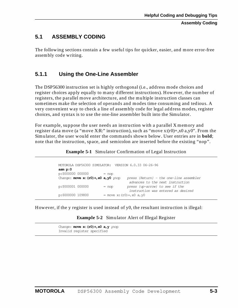
The DSP56300 instruction set is highly orthogonal (i.e., address mode choices and register choices apply equally to many different instructions). However, the number of registers, the parallel move architecture, and the multiple instruction classes can sometimes make the selection of operands and modes time consuming and tedious. A very convenient way to check a line of assembly code for legal address modes, register choices, and syntax is to use the one-line assembler built into the Simulator.
For example, suppose the user needs an instruction with a parallel X memory and register data move (a “move X:R:” instruction), such as “move x:(r0)+,x0 a,y0”. From the Simulator, the user would enter the commands shown below. User entries are in bold; note that the instruction, space, and semicolon are inserted before the existing “nop”.
However, if the y register is used instead of y0, the resultant instruction is illegal:
Example 5-1 Simulator Confirmation of Legal Instruction
MOTOROLA DSP56300 SIMULATOR: VERSION 6.0.33 06-26-96asm p:0p:$000000 000000 = nopChange: move x:(r0)+,x0 a,y0 ; nop press {Return} - the one-line assembler
advances to the next instructionp:$000001 000000 = nop press {up-arrow} to see if the
instruction was entered as desiredp:$000000 109800 = move x:(r0)+,x0 a,y0
Example 5-2 Simulator Alert of Illegal Register
Change: move x:(r0)+,x0 a,y ; nopInvalid register specified
MOTOROLA DSP56300 Assembly Code Development 5-3
Helpful Coding and Debugging Tips
Assembly Coding
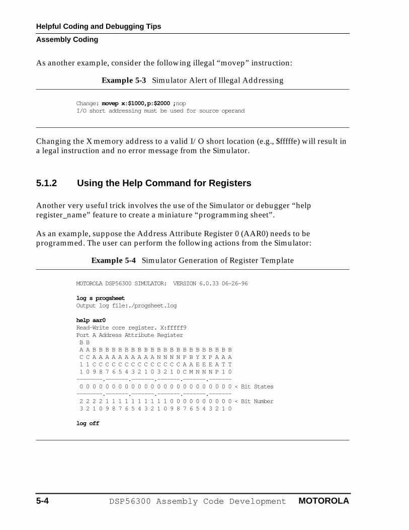
As another example, consider the following illegal “movep” instruction:
Changing the X memory address to a valid I/O short location (e.g., $fffffe) will result in a legal instruction and no error message from the Simulator.
5.1.2 Using the Help Command for Registers
Another very useful trick involves the use of the Simulator or debugger “help register_name” feature to create a miniature “programming sheet”.
As an example, suppose the Address Attribute Register 0 (AAR0) needs to be programmed. The user can perform the following actions from the Simulator:
Example 5-3 Simulator Alert of Illegal Addressing
Change: movep x:$1000,p:$2000 ; nopI/O short addressing must be used for source operand
Example 5-4 Simulator Generation of Register Template
MOTOROLA DSP56300 SIMULATOR: VERSION 6.0.33 06-26-96
log s progsheetOutput log file:./progsheet.log
help aar0Read-Write core register. X:fffff9Port A Address Attribute Register B B A A B B B B B B B B B B B B B B B B B B B B B B C C A A A A A A A A A A N N N N P B Y X P A A A 1 1 C C C C C C C C C C C C C C A A E E E A T T 1 0 9 8 7 6 5 4 3 2 1 0 3 2 1 0 C M N N N P 1 0--------.-------.-------.-------.-------.------- 0 0 0 0 0 0 0 0 0 0 0 0 0 0 0 0 0 0 0 0 0 0 0 0 < Bit States--------.-------.-------.-------.-------.------- 2 2 2 2 1 1 1 1 1 1 1 1 1 1 0 0 0 0 0 0 0 0 0 0 < Bit Number 3 2 1 0 9 8 7 6 5 4 3 2 1 0 9 8 7 6 5 4 3 2 1 0
log off
5-4 DSP56300 Assembly Code Development MOTOROLA
Helpful Coding and Debugging Tips
Assembly Coding
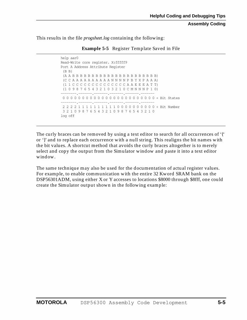
This results in the file progsheet.log containing the following:
The curly braces can be removed by using a text editor to search for all occurrences of ‘{‘ or ‘}’ and to replace each occurrence with a null string. This realigns the bit names with the bit values. A shortcut method that avoids the curly braces altogether is to merely select and copy the output from the Simulator window and paste it into a text editor window.
The same technique may also be used for the documentation of actual register values. For example, to enable communication with the entire 32 Kword SRAM bank on the DSP56301ADM, using either X or Y accesses to locations $8000 through $8fff, one could create the Simulator output shown in the following example:
Example 5-5 Register Template Saved in File
help aar0Read-Write core register. X:fffff9Port A Address Attribute Register {B B} {A A B B B B B B B B B B B B B B B B B B B B B B} {C C A A A A A A A A A A N N N N P B Y X P A A A} {1 1 C C C C C C C C C C C C C C A A E E E A T T} {1 0 9 8 7 6 5 4 3 2 1 0 3 2 1 0 C M N N N P 1 0}--------.-------.-------.-------.-------.------- 0 0 0 0 0 0 0 0 0 0 0 0 0 0 0 0 0 0 0 0 0 0 0 0 < Bit States--------.-------.-------.-------.-------.------- 2 2 2 2 1 1 1 1 1 1 1 1 1 1 0 0 0 0 0 0 0 0 0 0 < Bit Number 3 2 1 0 9 8 7 6 5 4 3 2 1 0 9 8 7 6 5 4 3 2 1 0log off
MOTOROLA DSP56300 Assembly Code Development 5-5
Helpful Coding and Debugging Tips
Assembly Coding
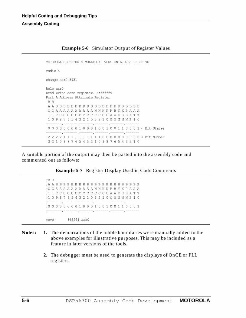
A suitable portion of the output may then be pasted into the assembly code and commented out as follows:
Notes: 1. The demarcations of the nibble boundaries were manually added to the above examples for illustrative purposes. This may be included as a feature in later versions of the tools.
2. The debugger must be used to generate the displays of OnCE or PLL registers.
Example 5-6 Simulator Output of Register Values
MOTOROLA DSP56300 SIMULATOR: VERSION 6.0.33 06-26-96
radix h
change aar0 8931
help aar0Read-Write core register. X:fffff9Port A Address Attribute Register B B A A B B B B B B B B B B B B B B B B B B B B B B C C A A A A A A A A A A N N N N P B Y X P A A A 1 1 C C C C C C C C C C C C C C A A E E E A T T 1 0 9 8 7 6 5 4 3 2 1 0 3 2 1 0 C M N N N P 1 0--------.-------.-------.-------.-------.------- 0 0 0 0 0 0 0 0 1 0 0 0 1 0 0 1 0 0 1 1 0 0 0 1 < Bit States--------.-------.-------.-------.-------.------- 2 2 2 2 1 1 1 1 1 1 1 1 1 1 0 0 0 0 0 0 0 0 0 0 < Bit Number 3 2 1 0 9 8 7 6 5 4 3 2 1 0 9 8 7 6 5 4 3 2 1 0
Example 5-7 Register Display Used in Code Comments
;B B;A A B B B B B B B B B B B B B B B B B B B B B B;C C A A A A A A A A A A N N N N P B Y X P A A A;1 1 C C C C C C C C C C C C C C A A E E E A T T;1 0 9 8 7 6 5 4 3 2 1 0 3 2 1 0 C M N N N P 1 0;-------.-------.-------.-------.-------.-------;0 0 0 0 0 0 0 0 1 0 0 0 1 0 0 1 0 0 1 1 0 0 0 1 ;-------.-------.-------.-------.-------.-------
move #$8931,aar0
5-6 DSP56300 Assembly Code Development MOTOROLA
Helpful Coding and Debugging Tips
Debugging
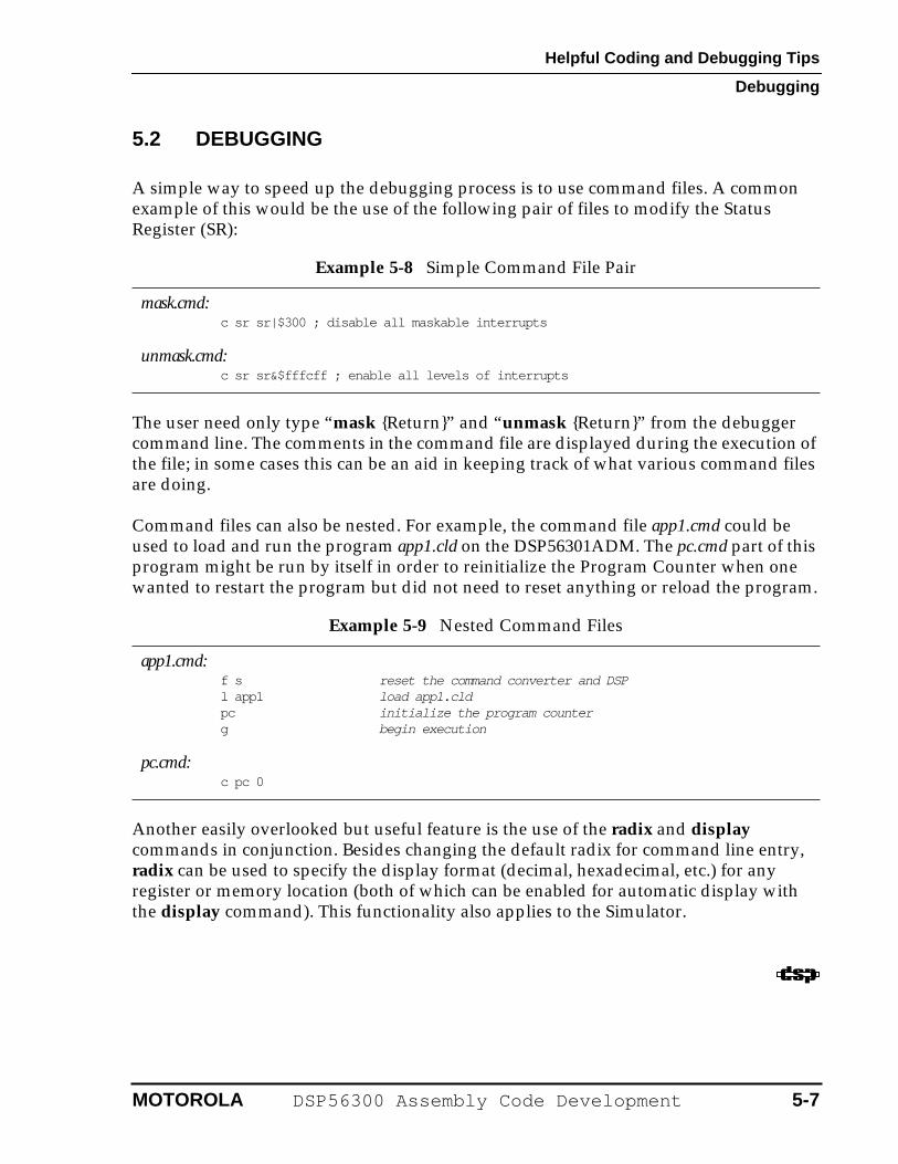
5.2 DEBUGGING
A simple way to speed up the debugging process is to use command files. A common example of this would be the use of the following pair of files to modify the Status Register (SR):
The user need only type “mask {Return}” and “unmask {Return}” from the debugger command line. The comments in the command file are displayed during the execution of the file; in some cases this can be an aid in keeping track of what various command files are doing.
Command files can also be nested. For example, the command file app1.cmd could be used to load and run the program app1.cld on the DSP56301ADM. The pc.cmd part of this program might be run by itself in order to reinitialize the Program Counter when one wanted to restart the program but did not need to reset anything or reload the program.
Another easily overlooked but useful feature is the use of the radix and display commands in conjunction. Besides changing the default radix for command line entry, radix can be used to specify the display format (decimal, hexadecimal, etc.) for any register or memory location (both of which can be enabled for automatic display with the display command). This functionality also applies to the Simulator.
Example 5-8 Simple Command File Pair
mask.cmd:c sr sr|$300 ; disable all maskable interrupts
unmask.cmd: c sr sr&$fffcff ; enable all levels of interrupts
Example 5-9 Nested Command Files
app1.cmd: f s reset the command converter and DSPl app1 load app1.cldpc initialize the program counterg begin execution
pc.cmd: c pc 0
MOTOROLA DSP56300 Assembly Code Development 5-7
Helpful Coding and Debugging Tips
Debugging
5-8 DSP56300 Assembly Code Development MOTOROLA