Embed Size (px)
Citation preview

f the
dingetchmber
ing
t and
ssing
Appendix AInstruction Timing and RestrictionsThis appendix describes the various aspects of execution timing analysis for eachinstruction mnemonic and for various instruction sequences. The section consists ofollowing tables and information:
■ Tables showing how to calculate DSP56300 core instruction timing for eachinstruction mnemonic (instruction timing)
■ Tables showing the number of instruction program words for each instructionmnemonic (instruction program words)
■ Description of various sequences that cause timing delays and stalls in theexecution (instruction sequence delays)
■ Description of various instruction sequences that are forbidden and causeundefined operation (instruction sequence restrictions)
A.1 Overview
The number of oscillator clock cycles per instruction depends on many factors, incluthe number of words per instruction, the addressing mode, whether the instruction fpipeline is full, the number of external bus accesses, cache hit/miss/burst, and the nuof wait states inserted into each external access.
Table A-1 lists instruction timing and is based on the assumption that all instructioncycles are counted in clock cycles and the instruction fetch pipeline is full. The followterms are used inside the table:
■ T: clock cycles for the normal case:
— All instructions fetched from the internal program memory
— No interlocks with previous instructions
— Addressing mode is the Post-Update mode (post-increment, post-decremenpost offset by N) or the No-Update mode.
■ + pru : Pre-update specifies clock cycles added for using the pre-update addremodes (pre-decrement and offset by N addressing modes).
Motorola DSP56300 Family Manual A-1
Overview
iate
■ + lab: Long absolute specifies clock cycles added for using the Long AbsoluteAddress mode.
■ + lim: Long immediate specifies clock cycles added for using the long immeddata addressing mode.
Note: A dash under one or more of the columnspru , lab, or lim indicates that thiscolumn is not applicable to the corresponding instruction.
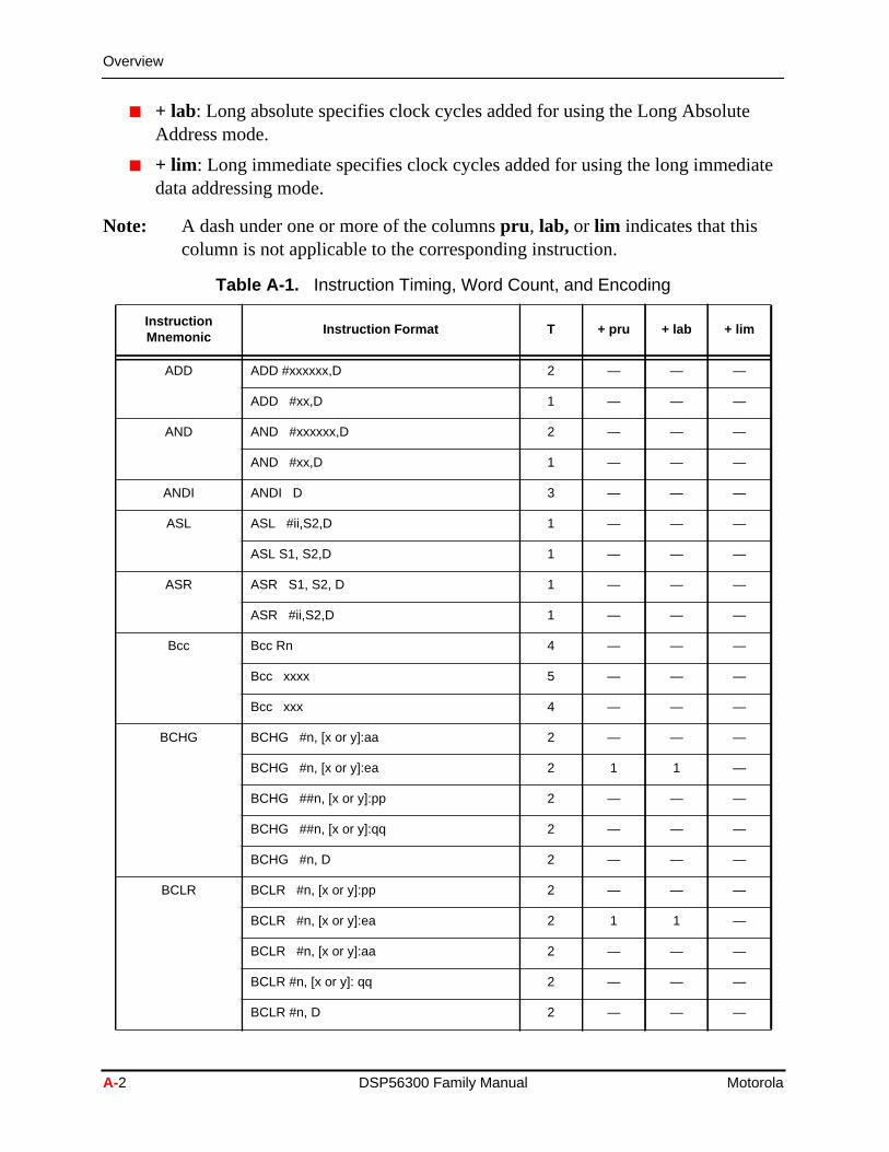
Table A-1. Instruction Timing, Word Count, and Encoding
InstructionMnemonic
Instruction Format T + pru + lab + lim
ADD ADD #xxxxxx,D 2 — — —
ADD #xx,D 1 — — —
AND AND #xxxxxx,D 2 — — —
AND #xx,D 1 — — —
ANDI ANDI D 3 — — —
ASL ASL #ii,S2,D 1 — — —
ASL S1, S2,D 1 — — —
ASR ASR S1, S2, D 1 — — —
ASR #ii,S2,D 1 — — —
Bcc Bcc Rn 4 — — —
Bcc xxxx 5 — — —
Bcc xxx 4 — — —
BCHG BCHG #n, [x or y]:aa 2 — — —
BCHG #n, [x or y]:ea 2 1 1 —
BCHG ##n, [x or y]:pp 2 — — —
BCHG ##n, [x or y]:qq 2 — — —
BCHG #n, D 2 — — —
BCLR BCLR #n, [x or y]:pp 2 — — —
BCLR #n, [x or y]:ea 2 1 1 —
BCLR #n, [x or y]:aa 2 — — —
BCLR #n, [x or y]: qq 2 — — —
BCLR #n, D 2 — — —
A-2 DSP56300 Family Manual Motorola
Overview
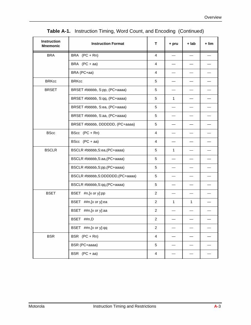
BRA BRA (PC + Rn) 4 — — —
BRA (PC + aa) 4 — — —
BRA (PC+aa) 4 — — —
BRKcc BRKcc 5 — — —
BRSET BRSET #bbbbb, S:pp, (PC+aaaa) 5 — — —
BRSET #bbbbb, S:qq, (PC+aaaa) 5 1 — —
BRSET #bbbbb, S:ea, (PC+aaaa) 5 — — —
BRSET #bbbbb, S:aa, (PC+aaaa) 5 — — —
BRSET #bbbbb, DDDDDD, (PC+aaaa) 5 — — —
BScc BScc (PC + Rn) 4 — — —
BScc (PC + aa) 4 — — —
BSCLR BSCLR #bbbbb,S:ea,(PC+aaaa) 5 1 — —
BSCLR #bbbbb,S:aa,(PC+aaaa) 5 — — —
BSCLR #bbbbb,S:pp,(PC+aaaa) 5 — — —
BSCLR #bbbbb,S:DDDDDD,(PC+aaaa) 5 — — —
BSCLR #bbbbb,S:qq,(PC+aaaa) 5 — — —
BSET BSET #n,[x or y]:pp 2 — — —
BSET ##n,[x or y]:ea 2 1 1 —
BSET ##n,[x or y]:aa 2 — — —
BSET ##n,D 2 — — —
BSET ##n,[x or y]:qq 2 — — —
BSR BSR (PC + Rn) 4 — — —
BSR (PC+aaaa) 5 — — —
BSR (PC + aa) 4 — — —
Table A-1. Instruction Timing, Word Count, and Encoding (Continued)
InstructionMnemonic
Instruction Format T + pru + lab + lim
Motorola Instruction Timing and Restrictions A-3

Overview
BSSET BSSET #bbbbb,S:pp,(PC+aaaa) 5 — — —
BSSET #bbbbb,S:ea,(PC+aaaa) 5 1 — —
BSSET #bbbbb,S:aa,(PC+aaaa) 5 — — —
BSSET #bbbbb,S:DDDDDD,(PC+aaaa) 5 — — —
BSSET #bbbbb,S:qq,(PC+aaaa) 5 — — —
BTST BTST #n,[x or y]:pp 2 — — —
BTST #n,[x or y]:ea 2 1 1 —
BTST #n,[x or y]:aa 2 — — —
BTST #n,D 2 — — —
BTST #n,[x or y]:qq 2 — — —
CLB CLB S,D 1 — — —
CMP CMP #iiiiii,D 2 — — —
CMP #iii,D 1 — — —
CMPU CMPU S1, S2 1 — — —
DEBUG/DEBUGcc
DEBUG 1 — — —
DEBUGcc 5 — — —
DEC DEC D 1 — — —
DIV DIV S, D 1 — — —
DMAC DMAC S1,S2,D (ss,su,uu) 1 — — —
DO DO #xxx,aaaa 5 — — —
DO DDDDDD,aaaa 5 — — —
DO S:<ea>,aaaa 5 1 — —
DO S:<aa>,aaaa 5 — — —
DO FOREVER DO FOREVER ,(aaaa) 4 — — —
DOR DOR #xxx,(PX+aaaa) 5 — — —
DOR DDDDDD,(PC+aaaa) 5 — — —
DOR S:ea,(PC+aaaa) 5 1 — —
DOR S:aa,(PC+aaaa) 5 — — —
Table A-1. Instruction Timing, Word Count, and Encoding (Continued)
InstructionMnemonic
Instruction Format T + pru + lab + lim
A-4 DSP56300 Family Manual Motorola

Overview
DOR FOREVER DOR FOREVER,(PC+aaaa)
ENDDO ENDDO 1 — — —
EOR EOR #xx,D 2 — — —
EOR #iii,D 1 — — —
EXTRACT EXTRACT S1,S2,D 1 — — —
EXTRACT #iiii,s,D 2 — — —
EXTRACTU EXTRACTU S1,S2,D 1 — — —
EXTRACTU #iiii,s,D 2 — — —
IFcc IFcc 1 — — —
ILLEGAL ILLEGAL 5 — — —
INC INC D 1 — — —
INSERT INSERT S1,S2,D 1 — — —
INSERT #iiii,qqq,D 2 — — —
Jcc Jcc xxx 4 — — —
Jcc ea 4 0 0 —
JCLR JCLR #n,[x or y]:ea,xxxx 4 1 — —
JCLR #n,[x or y]:pp,xxxx 4 — — —
JCLR #n,[x or y]:aa,xxxx 4 — — —
JCLR #n,S,xxxx 4 — — —
JCLR #n,[x or y]:qq,xxxx 4 — — —
JMP JMP aa 3 — — —
JMP ea 3 1 1 —
JScc JScc aa 4 — — —
JScc ea 4 0 0 —
Table A-1. Instruction Timing, Word Count, and Encoding (Continued)
InstructionMnemonic
Instruction Format T + pru + lab + lim
Motorola Instruction Timing and Restrictions A-5

Overview
JSCLR JSCLR #n,[x or y]:pp,xxxx 4 — — —
JSCLR #n,[x or y]:ea,xxxx 4 1 — —
JSCLR #n,[x or y]:aa,xxxx 4 — — —
JSCLR #n,S,xxxx 4 — — —
JSCLR #n,[x or y]:qq,xxxx 4 — — —
JSET JSET #n,[x or y]:pp,xxxx 4 — — —
JSET #n,[x or y]:ea,xxxx 4 1 — —
JSET #n,[x or y]:aa,xxxx 4 — — —
JSET #n,S,xxxx 4 — — —
JSET #n,[x or y]:qq,xxxx 4 — — —
JSR JSR aa 3 — — —
JSR ea 3 1 1 —
JSSET JSSET #n,[x or y]:pp,xxxx 4 — — —
JSSET #n,[x or y]:ea,xxxx 4 1 — —
JSSET #n,[x or y]:aa,xxxx 4 — — —
JSSET #n,S,xxxx 4 — — —
JSSET #n,[x or y]:qq,xxxx 4 — — —
LSL LSL S,D 1 — — —
LSL #ii,D 1 — — —
LSR LSR #ii,D 1 — — —
LSR S,D 1 — — —
LRA LRA (PC + Rn) → 0DDDDD 3 — — —
LRA (PC + aaaa) → 0DDDDD 3 — — —
LUA, LEA LUA ea → 0DDDDD 3 — — —
LUA (Rn + aa) → 01DDDD 3 — — —
MACI MACI ± #xxxxxx,S,D 2 — — —
MAC MAC ± 2**s,QQ,d 1 — — —
MAC S1,S2,D (su,uu) 1 — — —
Table A-1. Instruction Timing, Word Count, and Encoding (Continued)
InstructionMnemonic
Instruction Format T + pru + lab + lim
A-6 DSP56300 Family Manual Motorola

Overview
MACRI MACRI ± #iiiiii,QQ,D 2 — — —
MACR MACR ±2**s,QQ,d 1 — — —
MAX MAX A,B 1 — — —
MAXM MAXM A,B 1 — — —
MERGE MERGE S,D 1 — — —
MOVE No parallel data Move (DALU) 1 — — —
MOVE #xx,D 1 — — —
MOVE S,D 1 — — —
MOVE ea (U move, address registerupdate)
1 — — —
MOVE [x or y]:ea,D 1 1 1 1
MOVE S,[x or y]:ea 1 1 1 1
MOVE #xxxxxx,D 1 1 1 1
MOVE [x or y]:aa,D 1 — — —
MOVE [x or y]aa 2 — — —
MOVE [x or y]:(Rn+xxx),D 2 — — —
MOVE S,[x or y]:(Rn+xxx) 2 — — —
MOVE [x or y]:(Rn+xxxx),D 3 — — —
MOVE S,[x or y]:(Rn+xxxx) 3 — — —
MOVE X:ea,D1,S2,D2 1 1 1 1
MOVE S1,S:ea S2,D2 1 1 1 1
MOVE #xxxxxx,D1 S2,D2 1 1 1 1
MOVE S1,D1 Y:ea,D2 1 1 1 1
MOVE S1,D1 S2,Y:ea 1 1 1 1
MOVE S1,D1 #xxxxxx,D2 1 1 1 1
MOVE A,X:ea X0,A 1 1 — —
MOVE B,X:ea X0,B 1 1 — —
MOVE Y0 A,A,Y:ea 1 1 — —
Table A-1. Instruction Timing, Word Count, and Encoding (Continued)
InstructionMnemonic
Instruction Format T + pru + lab + lim
Motorola Instruction Timing and Restrictions A-7

Overview
MOVE cont. MOVE Y0 B,B,Y:ea 1 1 — —
MOVE L:ea,DMOVE S,L:ea
1 1 1 —
MOVE X:eax,D1 Y:eay,D2 1 — — —
MOVE X:eax,D1 S2,Y:eay 1 — — —
MOVE S1,X:eax Y:eay,D2 1 — — —
MOVE S1,X:eax S2,Y:eay 1 — — —
MOVEC MOVEC #xx,D1 1 — — —
MOVEC [x or y]:ea,D1 1 1 1 1
MOVEC S1,[x or y]:ea 1 1 1 1
MOVEC #xxxxxx,D1 1 1 1 1
MOVEC [x or y]:aa,D1 1 — — —
MOVEC S1,[x or y]:aa 1 — — —
MOVEC S1,D2 1 — — —
MOVEC S2,D1 1 — — —
MOVEM MOVEM S,P:ea 6 1 1 —
MOVEM P:ea,D 6 1 1 —
MOVEM S,P:aa 6 — — —
MOVEM P:aa,D 6 — — —
MOVEP MOVEP [x or y]:pp,[x or y]:ea 2 1 1 0
MOVEP [x or y]:ea,[x or y]:pp 2 1 1 0
MOVEP [x or y]:qq,[x or y]:ea 2 1 1 0
MOVEP [x or y]:ea,[x or y]:qq 2 1 1 0
MOVEP [x or y]:pp,P:ea 6 1 1 —
MOVEP P:ea,[x or y]:pp 6 1 1 —
MOVEP [x or y]:qq,P:ea 6 1 1 —
MOVEP P:ea,[x or y]:qq 6 1 1 —
MOVEP [x or y]:pp,D 1 — — —
Table A-1. Instruction Timing, Word Count, and Encoding (Continued)
InstructionMnemonic
Instruction Format T + pru + lab + lim
A-8 DSP56300 Family Manual Motorola

Overview
MOVEP cont. MOVEP S,[x or y]:pp 1 — — —
MOVEP [x or y]:qq,D 1 — — —
MOVEP S,[x or y]:qq 1 — — —
MPY MPY S1,S2,D (su,uu) 1 — — —
MPY ± 2**s,QQ,d 1 — — —
MPYI MPYI (I)#xxxxxx,S,D 2 — — —
MPYR MPYR ± 2**s,QQ,d 1 — — —
MPYRI MPYRI ± #iiiiii,QQ,D 2 — — —
NOP NOP 1 — — —
NORM NORM 5 — — —
NORMF NORMF S,D 1 — — —
OR OR #xx,D 2 — — —
OR #iii,D 1 — — —
ORI OR(I) D 3 — — —
PFLUSH PFLUSH 1 — — —
PFLUSHUN PFLUSHUN 1 — — —
PFREE PFREE 1 — — —
PLOCK PLOCK ea 2 1 1 —
PLOCKR PLOCKR (PC+aaaa) 4 — — —
PUNLOCK PUNLOCK ea 2 1 1 —
PUNLOCKR PUNLOCKR (PC+aaaa) 4 — — —
REP REP #xxx 5 — — —
REP S 5 — — —
REP [x or y]:ea 5 1 — —
REP [x or y]:aa 5 — — —
RESET RESET 7 — — —
RTI/RTS RTI 3 — — —
RTS 3 — — —
Table A-1. Instruction Timing, Word Count, and Encoding (Continued)
InstructionMnemonic
Instruction Format T + pru + lab + lim
Motorola Instruction Timing and Restrictions A-9

Instruction Sequence Delays
se a
pes of
r datack. The
A.2 Instruction Sequence Delays
Because of pipelining in the DSP56300 core, certain instruction sequences can caudelay in the execution of instructions. Most of these sequences are caused by asource-destination conflict or by the need to access the external bus. There are six tysequence delays:
■ External bus wait states
■ Instruction fetch delays
■ Data ALU interlocks
■ Address register interlocks
■ Stack extension delays
■ Pipeline interlocks
A.2.1 External Bus Wait States
An external bus wait state is caused by an instruction accessing the external bus foread or write. The execution time of the instruction is increased by the number of clocycles equal to the number of wait states programmed for that external data accessexact number of wait states depends on the type of memory accessed.
STOP STOP 10 — — —
SUB SUB #xx,D 2 — — —
SUB #iii,D 1 — — —
Tcc Tcc S1,D1,S2,D2 1 — — —
Tcc S1,D1 1 — — —
Tcc S2,D2 1 — — —
TRAP/TRAPcc
TRAP 9 — — —
TRAPcc 9 — — —
VSL VSL S,i,L:ea 1 1 1 —
WAIT WAIT 10 — — —
Table A-1. Instruction Timing, Word Count, and Encoding (Continued)
InstructionMnemonic
Instruction Format T + pru + lab + lim
A-10 DSP56300 Family Manual Motorola

Instruction Sequence Delays
the
she
n of
0,ovengas itsthe
terdingcle
sscond
en.
A.2.2 Instruction Fetch Delays
At an external instruction fetch, the effective number of stall states in the pipeline is number specified in the Bus Control Register (BCR).
A.2.3 Data ALU Interlock
A Data ALU interlock is caused by one of the following sequences:
■ Arithmetic stall: Occurs when an instruction uses one of the Data ALU register(A0, A1, A2, B0, B1, or B2) or accumulators (A or B) as a source register for tmove portion of the instruction when the preceding instruction is an arithmeticinstruction1 that uses the same accumulator as its destination. Delays executiothe initiating instruction by one clock cycle.
■ Transfer stall:Occurs when an instruction uses one of the Data ALU registers (AA1, A2, B0, B1, or B2) or accumulators (A or B) as a source register for the mportion of the instruction when the preceding instruction uses the correspondiaccumulator or one of the Data ALU registers that comprise the accumulator destination register in the move portion of that instruction. Delays execution ofinitiating instruction by one instruction cycle.
■ Status stall:Occurs when an instruction reads the contents of the Status Regis(SR) for either a move operation or bit testing and the preceding or the seconpreceding instruction is an arithmetic instruction. Delays execution of the initiatinstruction by two instruction cycles for a move operation or one instruction cyfor bit testing.
A.2.4 Address Register Interlocks
An address register interlock is caused by one of the following sequences:
■ Conditional Transfer Interlock: Occurs when a Transfer On-Condition (Tcc)instruction is followed by an instruction that explicitly specifies one of the addregeneration registers (R0–R7) as its source operand. Delays execution of the seinstruction by one instruction cycle.
■ Address Generation Interlock: Occurs when the move portion of an instructionuses one of the AGU registers R0–R7 for address generation or for addresscalculation, while one of the three preceding instruction cycles uses one of thregister set (Ri, Ni or Mi) members as a destination register in its move portioConsiderExample A-1.
1. An arithmetic instruction uses the internal Data ALU data paths.
Motorola Instruction Timing and Restrictions A-11
Instruction Sequence Delays
R0 astion,
typesd the
the
ehee
.
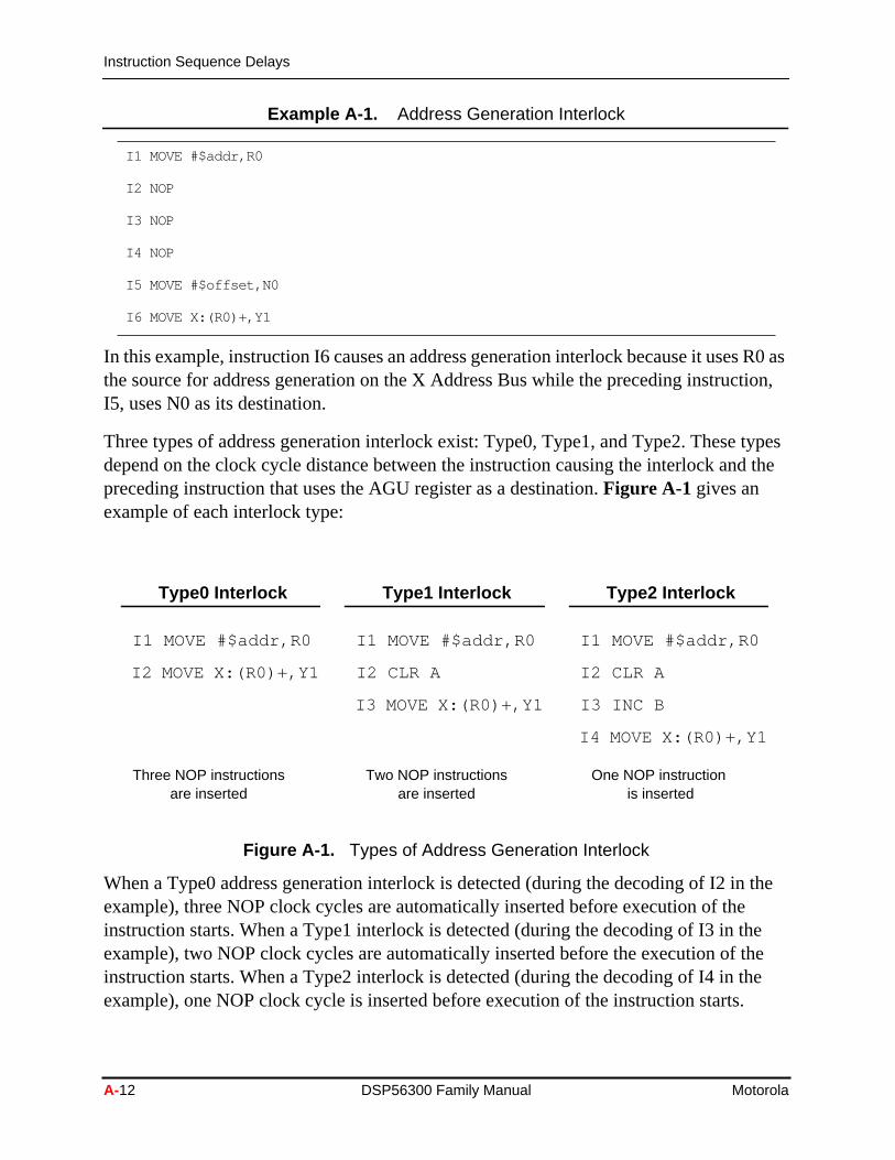
In this example, instruction I6 causes an address generation interlock because it usesthe source for address generation on the X Address Bus while the preceding instrucI5, uses N0 as its destination.
Three types of address generation interlock exist: Type0, Type1, and Type2. Thesedepend on the clock cycle distance between the instruction causing the interlock anpreceding instruction that uses the AGU register as a destination.Figure A-1 gives anexample of each interlock type:
When a Type0 address generation interlock is detected (during the decoding of I2 inexample), three NOP clock cycles are automatically inserted before execution of theinstruction starts. When a Type1 interlock is detected (during the decoding of I3 in thexample), two NOP clock cycles are automatically inserted before the execution of tinstruction starts. When a Type2 interlock is detected (during the decoding of I4 in thexample), one NOP clock cycle is inserted before execution of the instruction starts
Example A-1. Address Generation Interlock
I1 MOVE #$addr,R0
I2 NOP
I3 NOP
I4 NOP
I5 MOVE #$offset,N0
I6 MOVE X:(R0)+,Y1
Figure A-1. Types of Address Generation Interlock
Type0 Interlock
I1 MOVE #$addr,R0
I2 MOVE X:(R0)+,Y1
Type1 Interlock
I1 MOVE #$addr,R0
I2 CLR A
I3 MOVE X:(R0)+,Y1
Type2 Interlock
I1 MOVE #$addr,R0
I2 CLR A
I3 INC B
I4 MOVE X:(R0)+,Y1
Three NOP instructionsare inserted
Two NOP instructionsare inserted
One NOP instructionis inserted
A-12 DSP56300 Family Manual Motorola

Instruction Sequence Delays
e
s theeding thelock is
dress
two noif I3 bere the
n theagedrmed.r aen theword
tacksion
only
Note: Only clock cycles are counted to determine when interlock cycles should binserted.
When an instruction using one of the AGU registers as an address generation enterdecoding stage of the DSP56300 core, the distance from that instruction to the precinstruction using the register as destination is measured in clock cycles to determineexistence and type of address generation interlock. Once an address generation interdetected, the appropriate number of NOP clock cycles is inserted. The followinginstructions take these additional cycles into account for detecting a possible new adgeneration interlock.Example A-2 demonstrates this feature.
In this example, a Type1 interlock is detected during the decoding phase of I 3 and NOP cycles are inserted before that instruction executes. During the decoding of I4,address generation interlock is detected, so no NOP cycles are inserted. However, were an instruction that did not use R0, a Type2 address generation interlock woulddetected during the decoding phase of I4, and one NOP cycle would be inserted befoinstruction executes.
A.2.5 Stack Extension Delays
Some instructions access the System Stack (SS) as part of their normal activity. WheSS is either completely full or empty, the special stack extension mechanism is engand the access completes only after an access to data memory is automatically perfoThis delays the decoding and the execution phases of that instruction. A stack-full ostack-empty state is defined by the contents of the Stack Counter (SC) register. Whstack counter equals 14, the on-chip hardware stack contains fourteen words (a stackis a 48-bit long word combined from the low and the high portions of the stack). The sis declared as stack-full, and any additional push operation activates the stack extenmechanism. When the stack counter equals 2, the on-chip hardware stack containstwo words. The stack is declared as stack-empty, and any additional pop operationsactivate the stack extension mechanism. The instructions/cases listed inTable A-2 causean access to the system stack and may engage the stack extension mechanism.
Example A-2. Detection of Address Generation Interlock
I1 MOVE #$addr,R0
I2 CLR A
I3 MOVE X:(R0)+,Y1
I4 MOVE X:(R0)+,Y0
Motorola Instruction Timing and Restrictions A-13

Instruction Sequence Delays
:
Table A-3 shows how many clock cycles are added in the various instructions/casesdescribed.
:
Table A-2. Instructions That Access the System Stack
Instruction Description
JSR, Jcc All the conditional and unconditional Jump to Subroutine instructions (e.g., JSR, JSSET,and so on). These instructions perform a stack PUSH operation that stores the PC and theSR on top of the stack for the use of the ‘Return from Subroutine’ instruction that terminatesthe subroutine execution.
RET The two Return from Subroutine instructions, RTS and RTI. These instructions perform astack POP operations that pulls the PC and (optionally) the SR out from the top of stack inorder to return to the calling procedure and restore the status bits and loop flag state.
END-OF-DO A condition of the hardware inside the Program Control Unit. This hardware detects a fetchfrom the last address of a loop initiated when the Loop Counter equals 1. This conditiondefines the end of the loop, thus performing a stack POP operation. This POP operationrestores the loop flag, purges the top of stack (PC:SR), and pulls LA and LC from the newtop of stack.
LOOP All the hardware-loop initiating instructions (e.g., DO) with all their options. Theseinstructions perform a stack double-PUSH operation that first stores the previous values ofLA and LC on top of the stack. Then the DO instruction stores the contents of SR and PC onthe new top of stack. This PC value is used every loop iteration to return to the top of looplocation and start fetch from there. DO performs two accesses to the stack instead of thenormal single access done by most stack operations.
ENDDO A special instruction that forces an end-of-do condition during a hardware loop. LikeEND-OF-DO, ENDDO performs two accesses to the stack instead of the normal singleaccess done by most stack operations.
SSHWR All the explicit stack PUSH instructions that use SSH as their destination (e.g., the MOVER0,SSH instruction).
SSHRD All the explicit stack POP instructions that use SSH as their source (e.g., the MOVE SSH,Y1instruction).
Table A-3. Stack Extension Delays
CASEStack Full Condition
( + clock cycles )Stack Empty Condition
( + clock cycles )
JSR, Jcc 2 —
RET — 3
END-OF-DO — 5
DO 4 —
ENDDO — 5
SSHWR 2 —
SSHRD — 3
A-14 DSP56300 Family Manual Motorola

Instruction Sequence Delays
e
ions
nd
f theyction
eTI
s
A.2.6 Program Flow Control Delays
When flow-control instructions execute, some boundary cases exist and introduceinterlocks into the program flow. These interlocks lengthen the decoding phase of thinstructions, thus delaying execution. The following sequences represent unusualoperations that will probably never be used. The detection of these cases and thegeneration of interlocks is done to maintain object code compatibility between theDSP56300 core and the 56000 family of DSPs. The following terms are used in thisdiscussion:
■ I1: An address of an instruction, where I2, I3, and I4 indicate the next instructin the program flow
■ MOVE: any type of MOVE, MOVEM, MOVEP, MOVEC, BSET, BCHG, BCLR,and BTST
■ LA: the last address of a DO LOOP
■ (LA – 1): the address of an instruction word located at LA – 1
■ CR: Control Register, every one of the registers LA, LC, SR, SP, SSH, SSL, aOMR
A.2.6.1 JMP to LA or to LA – 1
When I1 is any type of JMP with its target address equal to LA, the decoding phase oinstruction following the instruction at LA is delayed by 2 clock cycles. When I1 is antype of JMP with its target address equal to LA – 1, the decoding phase of the instrufollowing the instruction at LA is delayed by one clock cycle.
A.2.6.2 RTI to LA or to LA – 1
When I1 is an RTI instruction whose return address is LA, the decoding phase of thinstruction following the instruction at LA is delayed by 2 clock cycles. When I1 is an Rinstruction whose return address is LA – 1, the decoding phase of the instructionfollowing the instruction at LA is delayed by one clock cycle.
A.2.6.3 Conditional Instructions
When I1 is a conditional change of flow instruction (such as Jcc) and the condition ifalse, the decoding phase of I2 is delayed by one clock cycle.
Motorola Instruction Timing and Restrictions A-15

Instruction Sequence Restrictions
bento
of I1
ction
nst oftackre
d as
d a
ne of
A.2.6.4 Interrupt Abort
When I1 is an instruction with a decoding phase that is longer than one cycle, it mayaborted by the Interrupt Control Unit. In this case, a 1 clock cycle “hole” is inserted ithe pipeline, after which the instruction at the interrupt vector is decoded.
A.2.6.5 Degenerated DO loop
When I1 is a DO loop but the loop contains only one instruction, the decoding phaseis lengthened by one clock cycle.
A.2.6.6 Annulled REP and DO
If the repeat count of a REP instruction is zero, the decoding phase of the REP instruis lengthened by one clock cycle. If the repeat count of a DO instruction is zero, thedecoding phase of the DO instruction is lengthened by three clock cycles.
A.3 Instruction Sequence Restrictions
Because of the pipelining in the DSP56300 core central processor, certain instructiosequences are forbidden. Use of these sequences causes undefined operation. Mothese restricted sequences cause contention for an internal resource, such as the SRegister. The DSP Assembler flags these as assembly errors. The following terms aused in this discussion:
■ MOVE: any type of MOVE, MOVEM, MOVEP, MOVEC
■ MOVEM: any type of MOVE to/from the Program space
■ LA: the last address of a DO LOOP
■ Two-words <inst>: a double-word instruction in which the second word is usean immediate data or absolute address
■ Single-word <inst>: an instruction with an addressing mode that does not neesecond word extension
A.3.1 Restrictions Near the End of DO Loops
Proper DO loop operation is not guaranteed for an instruction sequence similar to othe following sequences.
A-16 DSP56300 Family Manual Motorola
Instruction Sequence Restrictions
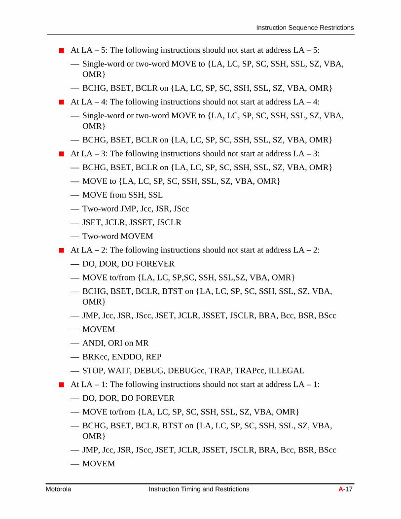
■ At LA – 5: The following instructions should not start at address LA – 5:
— Single-word or two-word MOVE to {LA, LC, SP, SC, SSH, SSL, SZ, VBA,OMR}
— BCHG, BSET, BCLR on {LA, LC, SP, SC, SSH, SSL, SZ, VBA, OMR}
■ At LA – 4: The following instructions should not start at address LA – 4:
— Single-word or two-word MOVE to {LA, LC, SP, SC, SSH, SSL, SZ, VBA,OMR}
— BCHG, BSET, BCLR on {LA, LC, SP, SC, SSH, SSL, SZ, VBA, OMR}
■ At LA – 3: The following instructions should not start at address LA – 3:
— BCHG, BSET, BCLR on {LA, LC, SP, SC, SSH, SSL, SZ, VBA, OMR}
— MOVE to {LA, LC, SP, SC, SSH, SSL, SZ, VBA, OMR}
— MOVE from SSH, SSL
— Two-word JMP, Jcc, JSR, JScc
— JSET, JCLR, JSSET, JSCLR
— Two-word MOVEM
■ At LA – 2: The following instructions should not start at address LA – 2:
— DO, DOR, DO FOREVER
— MOVE to/from {LA, LC, SP,SC, SSH, SSL,SZ, VBA, OMR}
— BCHG, BSET, BCLR, BTST on {LA, LC, SP, SC, SSH, SSL, SZ, VBA,OMR}
— JMP, Jcc, JSR, JScc, JSET, JCLR, JSSET, JSCLR, BRA, Bcc, BSR, BScc
— MOVEM
— ANDI, ORI on MR
— BRKcc, ENDDO, REP
— STOP, WAIT, DEBUG, DEBUGcc, TRAP, TRAPcc, ILLEGAL
■ At LA – 1: The following instructions should not start at address LA – 1:
— DO, DOR, DO FOREVER
— MOVE to/from {LA, LC, SP, SC, SSH, SSL, SZ, VBA, OMR}
— BCHG, BSET, BCLR, BTST on {LA, LC, SP, SC, SSH, SSL, SZ, VBA,OMR}
— JMP, Jcc, JSR, JScc, JSET, JCLR, JSSET, JSCLR, BRA, Bcc, BSR, BScc
— MOVEM
Motorola Instruction Timing and Restrictions A-17

Instruction Sequence Restrictions
e
s).
— ANDI, ORI on MR
— BRKcc, ENDDO, REP
— STOP, WAIT, DEBUG, DEBUGcc, TRAP, TRAPcc, ILLEGAL
Note: A one-word conditional branch instruction at LA-1 is not allowed.
When two consecutive LAs have a conditional branch instruction at LA-1 of thinternal loop, the device does not operate properly. For example, the followingsequence may generate incorrect results:
DO #5, LABEL1NOPDO #4, LABEL2NOPMOVE (R0) +BSCC _DEST ; conditional branch at LA-1 of internal loopNOP ; internal LA
LABEL2NOP ; external LA
LABEL1NOPNOP
_DEST NOPNOPRTS
Workaround: Put an additional NOP between LABEL2 and LABEL1.
■ At LA: The following instructions should not start at address LA:
— Any two-word instruction
— MOVE to {LA, LC, SP, SC, SSH, SSL, SZ, VBA, OMR}
— MOVE from SSH, SSL
— BCHG, BSET, BCLR on {LA, LC, SP, SC, SSH, SSL, SZ, VBA, OMR}
— BTST on SSH
— JMP, JSR, BRA, BSR, Jcc, JScc, Bcc, BScc
— MOVE to/from Program space {MOVEM, MOVEP (only the P space option
— RESET
— RTI, RTS
— ANDI, ORI on MR
— BRKcc, ENDDO, REP
— STOP, WAIT, DEBUG, DEBUGcc, TRAP, TRAPcc, ILLEGAL
A-18 DSP56300 Family Manual Motorola

Instruction Sequence Restrictions
s:
ged
to
DO
,
R,
R
cc}
sidestede
DO
A.3.2 General DO Restrictions
The general restrictions on DO instructions are as follows:
■ A DO loop should be initialized and aborted using only the following instructionDO, DOR, DO FOREVER, ENDDO, and BRKcc.
■ The LF and the FV bits in the Status Register (SR) should not be explicitly chanusing the MOVE, BCHG, BSET, BCLR, ANDI, or ORI instructions.
■ Proper DO loop operation is not guaranteed if an instruction sequence similarone of the following sequences is used.
— SSH cannot be used as the source for the Loop-Count for a DO, DOR, or aFOREVER instruction.
— The following instructions should not appear within four words before a DODOR, or DO FOREVER:
• BCHG, BCLR, BSET, MOVE on/to SSH,SSL
• BCHG, BCLR, BSET, MOVE on/to SP, SC
— The following instructions should not appear immediately before a DO, DOor DO FOREVER:
• MOVE from SSH
• BTST on SSH
• BCHG, BCLR, BSET, MOVE to/on {LA, LC, SP, SC, SSH, SSL}
• JSR, JScc, JSSET, JSCLR to LA whenever LF is set
• BSR, BScc, to LA whenever LF is set
— The following instructions should not appear in a DO, DOR, or DO FOREVEloop:
• {JMP, Jcc, JSR, JScc, JSET, JCLR, JSSET, JSCLR, BRA, Bcc, BSR, BS
When Stack Extension mode is enabled, use of the BRKcc or ENDDO instructions inDO loops may cause an improper operation. If the loop is not nested and has no neloop inside it, this restriction is relevant only if LA or LC values are in use outside thloop. If Stack Extension is used, emulate the BRKcc or ENDDO as shown in thefollowing examples in which there is a split between two cases, finite DO loops and FOREVER loops.
Motorola Instruction Timing and Restrictions A-19

Instruction Sequence Restrictions
Example A-3. Finite DO Loops
BRKcc
Original code:
do #N,label1..........
do #M,label2..........BRKcc..........
label2..........
label1
Will be replaced by:
do #N, label1..........
do #M, label2..........Jcc fix_brk_routine..........
nop_before_label2nop ; This instruction must be NOP.
label2..........
label1........
fix_brk_routinemove #1,lcjmp nop_before_label2
ENDDO------Original code:
do #M,label1..........
do #N,label2..........ENDDO..........
A-20 DSP56300 Family Manual Motorola

Instruction Sequence Restrictions
label2..........
label1
Will be replaced by:
do #M, label1..........
do #N, label2..........JMP fix_enddo_routine
nop_after_jmpNOP ; This instruction must be NOP...........
label2..........
label1........
fix_enddo_routinemove #1,lcmove #nop_after_jmp,lajmp nop_after_jmp
Example A-4. DO FOREVER Loops
BRKcc-----Original code:
do #M,label1..........
do forever,label2..........BRKcc..........
label2..........
label1
Will be replaced by:
do #M,label1..........
do forever,label2
Motorola Instruction Timing and Restrictions A-21

Instruction Sequence Restrictions
.....
.....JScc fix_brk_forever_routine ; <---
note: JScc and not Jcc..........
nop_before_label2nop ; This instruction must be NOP.
label2..........
label1........
fix_brk_forever_routinemove ssh,x:<..> ; <..> is some reserved not used
address (for temporary data)move #nop_before_label2,sshbclr #16,ssl ;move #1,lcrti ; <---- note: "rti" and not "rts" !
ENDDO------Original code:
do #M,label1..........
do forever,label2..........ENDDO..........
label2..........
label1
Will be replaced by:
do #M,label1..........
do forever,label2..........JSR fix_enddo_routine ; <--- note:
JSR and not JMPnop_after_jmp
NOP ; This instruction should be NOP..........
A-22 DSP56300 Family Manual Motorola
Instruction Sequence Restrictions
O
label2..........
label1........
fix_enddo_routinenopmove #1,lcbclr #16,sslmove #nop_after_jmp,larti ; <--- note: "rti" and not "rts"
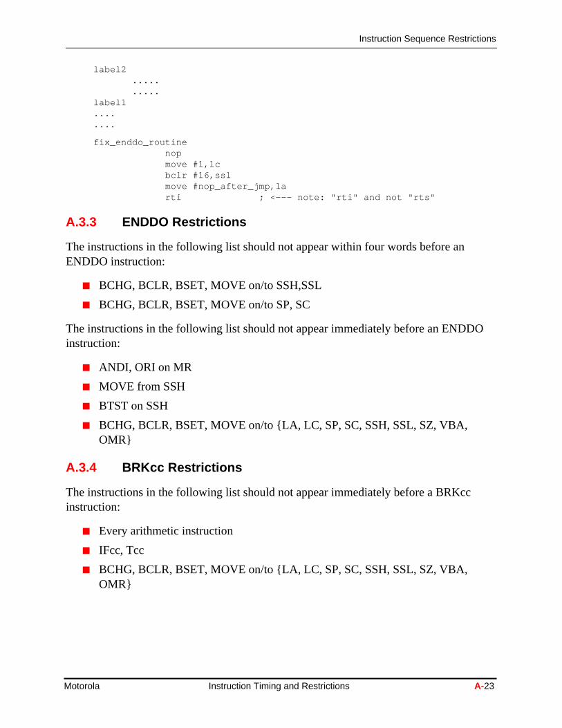
A.3.3 ENDDO Restrictions
The instructions in the following list should not appear within four words before anENDDO instruction:
■ BCHG, BCLR, BSET, MOVE on/to SSH,SSL
■ BCHG, BCLR, BSET, MOVE on/to SP, SC
The instructions in the following list should not appear immediately before an ENDDinstruction:
■ ANDI, ORI on MR
■ MOVE from SSH
■ BTST on SSH
■ BCHG, BCLR, BSET, MOVE on/to {LA, LC, SP, SC, SSH, SSL, SZ, VBA,OMR}
A.3.4 BRKcc Restrictions
The instructions in the following list should not appear immediately before a BRKccinstruction:
■ Every arithmetic instruction
■ IFcc, Tcc
■ BCHG, BCLR, BSET, MOVE on/to {LA, LC, SP, SC, SSH, SSL, SZ, VBA,OMR}
Motorola Instruction Timing and Restrictions A-23

Instruction Sequence Restrictions
I or
one
ting
A.3.5 RTI and RTS Restrictions
The instructions in the following list should not appear within four words before an RTRTS instruction:
■ BCHG, BCLR, BSET, MOVE on/to SSH,SSL
■ BCHG, BCLR, BSET, MOVE on/to SP, SC
The instructions in the following list should not appear immediately before an RTIinstruction:
■ MOVE, BCHG, BCLR, BSET on {SSH, SSL, SP, SC}
■ MOVE, BTST from/on SSH
■ ANDI, ORI on {MR, CCR}
■ ENDDO
The instructions in the following list should not appear immediately before an RTSinstruction:
■ MOVE, BCHG, BCLR, BSET on {SSH, SSL, SP, SC}
■ MOVE, BTST from/on SSH
■ ENDDO
A.3.6 SR Manipulation Restrictions
Changing values of bits in the Status Register (SR) should not be done explicitly usingof the MOVE, BCHG, BSET, BCLR instructions, but only using the ANDI or ORIinstructions with the appropriate 8-bit portion on the SR (MR, EMR, CCR).
A.3.7 SP/SC and SSH/SSL Manipulation Restrictions
The instructions in List A should not be executed within four instructions before execuany of the instructions in List B.
List A
■ MOVE to (SP, SC)
■ BCHG, BSET, BCLR on (SP, SC)
List B
■ MOVE to/from {SSH,SSL}
A-24 DSP56300 Family Manual Motorola

Instruction Sequence Restrictions
ionot
■ BTST, BCHG, BSET, BCLR on {SSH,SSL}
■ JSET, JCLR, JSSET, JSCLR on {SSH,SSL}
A.3.8 Fast Interrupt Routines
The following instructions cannot be used in a fast interrupt routine:
■ DO, DO FOREVER, REP
■ ENDDO, BRKcc
■ RTI, RTS
■ STOP, WAIT
■ TRAP, TRAPcc
■ ANDI, ORI on {MR, CCR}
■ MOVE from SSH
■ BTST on SSH
■ MOVE to {LA, LC, SP, SC, SSH, SSL}
■ BCHG, BSET, BCLR on {LA, LC, SP, SC, SSH, SSL}
A.3.9 REP Restrictions
The REP instruction can repeat any single-word instruction except the REP instructitself and any instruction that changes program flow. The following instructions are nallowed to follow a REP instruction (cannot be repeated):
■ REP, DO, DO FOREVER
■ ENDDO, BRKcc
■ JMP, Jcc, JCLR, JSET
■ JSR, JScc, JSCLR, JSSET
■ BRA, Bcc
■ BSR, BScc
■ RTS, RTI
■ TRAP, TRAPcc
■ WAIT, STOP
Motorola Instruction Timing and Restrictions A-25

Instruction Sequence Restrictions
. Two
SHR).
SH
ltSL
R,
esultSL
A.3.10 Stack Extension Restrictions
The following instructions, related to the operation of the on-chip hardware stackextension, cannot be used whenever the stack extension is enabled:
■ MOVE to EP
■ BCHG, BSET, BCLR on EP
■ MOVE to SC with a value greater than 15
The following instructions, related to the operation of the on-chip hardware stackextension, cannot be placed in the stack error vector locations whenever the stackextension is enabled:
■ JSR, JScc, JSCLR, JSSET
■ BSR, BScc
A.3.11 Stack Extension Enable Restrictions
When stack extansion is enabled, the read result from stack may be improper if twoprevious executed instructions cause sequential read and write operations with SSHcases are possible:
■ Case 1:
— For the first executed instruction: move from SSH or bit manipulation on S(i.e., JCLR, BRCLR, JSET, BRSET, BTST, BSSET, JSSET, BSCLR, JSCL
— For the second executed instruction: move to SSH or bit manipulation on S(i.e., JSR, BSR, JScc, BScc).
— For the third executed instruction: an SSL or SSH read from the stack resumay be improper. Move from SSH or SSL or bit manipulation on SSH or S(i.e., BSET, BCLR, BCHG, JCLR, BRCLR, JSET, BRSET, BTST, BSSET,JSSET, BSCLR, JSCLR).
Workaround: Add two NOP instructions before the third executed instruction.
■ Case 2:
— For the first executed instruction: bit manipulation on SSH (i.e., BSET, BCLBCJG).
— For the second executed instruction: an SSL or SSH read from the stack rmay be improper. Move from SSH or SSL or bit manipulation on SSH or S
A-26 DSP56300 Family Manual Motorola

Peripheral Pipeline Restrictions
n.
ivelylines
e ofesen
tivity.ve the
anyheralit isityst Datalyfore
(i.e., BSET, BCLR, BCHG, JCLR, BRCLR, JSET, BRSET, BTST, BSSET,JSSET, BSCLR, JSCLR).
Workaround: Add two NOP instructions before the second executed instructio
A.4 Peripheral Pipeline Restrictions
The DSP56300 core is based on a highly optimized pipeline engine. Despite the relatdeep pipeline (seven stages), the latency effects normally associated with long pipeare minimal because most of these effects are transparent to the user. Such designtechniques as forwarding and interlocking alleviate the need for a thorough knowledgthe machine’s pipeline in order to avoid data dependencies. This knowledge becomnecessary only when you are further optimizing the code. The assembler detects whtransparency does not exist (e.g., pointer restrictions) and generates an appropriatewarning message. However, the pipeline is exposed to the user during peripheral acThis section describes the cases in which you must take precautions in order to achiedesired functionality.
A.4.1 Polling a Peripheral Device for Write
When data is written to a peripheral device, there is a two-cycle pipeline delay until status bits affected by this operation are updated. For example, you operate a peripport using the polling technique. You look for the Data Empty flag to be set, and whenset, you write new data to the Transmit Data Register. If you try to read the status bwithin the next two cycles, the flag is mistakenly read as set due to the pipeline delaassociated with the peripheral operations. Therefore, if you assume that the TransmiRegister is empty and write a new data word, this data word overwrites the previouswritten data. To achieve the correct functionality, you must wait at least two cycles beattempting to read the Status Register after a write to the Transmit Data register.ExampleA-5 shows the correct sequence for transmit operations.
Example A-5. Providing a Wait for Proper Data Writes
send
movep x:(r0)+,x:STX ; send new data
nop ; pipeline delay
nop ; pipeline delay
poll
jclr #TDE,x:SCSR,poll ; wait for data empty
jmp send ; go to send data
Motorola Instruction Timing and Restrictions A-27

Sixteen-Bit Compatibility Mode Restrictions
de of of theou
s:
e isory.
cent
befter
A.4.2 Writing to a Read-Only Register
Writing to a read-only register is an operation that normally has no effect, but if a reaoperation from the same register is attempted within the following two cycles, the valuthe read data is the value of the data that was written instead of the unchanged dataread-only register. To ensure that the correct data is read after the write operation, ymust wait at least two cycles before performing the read.
A.4.3 XY Memory Data Move
An XY memory data move does not work properly in either of the following situation
■ The X-memory move destination is internal I/O and the Y-memory move sourca register used as destination in the previous adjacent move from non Y-mem
■ The Y-memory move destination is a register used as source in the next adjamove to non Y-memory.
Here are examples cases (where x:(r1) is a peripheral):
Example 1:
move #$12,y0move x0,x:(r7) y0,y:(r3) (while x:(r7) is a peripheral).
Example 2:
mac x1,y0,a x1,x:(r1)+ y:(r6)+,y0move y0,y1
To address this problem, use one of the following alternatives:
■ Separate these two consecutive moves by any other instruction.
■ Split the XY Data Move to two moves.
A.5 Sixteen-Bit Compatibility Mode Restrictions
When there is a return from a long interrupt (by the RTI instruction), and the firstinstruction after the RTI is a move to a DALU register (A, B, X, Y), the move may notcorrect if the 16-bit arithmetic mode bit (bit 17 of SR) is changed due to restoring SR aRTI. To address this problem, replace the RTI with the following sequence:
movec ssl,srnoprti
A-28 DSP56300 Family Manual Motorola