Embed Size (px)
Citation preview
xx/xx
J. Aerosp. Technol. Manag., São José dos Campos, v10, e0818, 2018
doi: 10.5028/jatm.v10.763 originaL paper
1.K. N. Toosi University of Technology – Faculty of Aerospace Engineering – Tehran/Tehran – Iran. 2.Islamic Azad University – Faculty of Mechanical Engineering – Takestan/Qazvin – Iran.
Author for correspondence: Amin Jafarimoghaddam | K. N. Toosi University of Technology – Faculty of Aerospace Engineering | Mirdamad Blvd, No. 470 | Tehran/Tehran – Iran | Email: [email protected]
received: Aug. 12, 2016 | accepted: Feb. 14, 2017
Section editor: Paulo Celso Greco
aBStraCt: This study aims to fi rst introduce a formulation which is quite simple for obtaining dielectric-barrier discharge plasma spatial body force. This new model comprises a combination of an empirical model and a numerical one. Although there are still some limitations in the new model (restriction to specifi c geometry, maximum voltage amplitude of 30 kV, maximum frequency of 30 kHz, dielectric coeffi cient of 2.8 and Debye length of 0.0001 m), it is straightforward compared to the existing ones. The model possesses a high accuracy for the abovementioned band. It is proposed an approximate integral solution for the wall jet problem which is associated with the induced jet produced by dielectric barrier discharge plasma actuator. The approximate integral solution for the wall jet is verifi ed by similarity, and the details are extensively discussed.
KeyWordS: DBD, Plasma actuator, Body force, Lumped circuit element, Electro-static model.
INTRODUCTION
Among the many models and schemes proposed so far to control the behavior of the fl uid fl ow, dielectric-barrier discharge (DBD) plasma actuator might be counted as the most recent one (Yang and Chung 2015; Gad-el-Hak 2000; Braun et al. 2009; Corke et al. 2010). Such an actuator has been used mainly for aerodynamic purposes, as fl ow reattachment, which subsequently leads to enhancing lift and drag reduction (Gad-el-Hak 2000; Braun et al. 2009; Corke et al. 2010; Moreau 2007; Cattafesta and Sheplak 2011; Zhang et al. 2010; Aberoumand et al. 2016). Owing to the fact that experimental investigations on DBD plasma actuators demand high costs for providing the setup apparatus, Computational Fluid Dynamics (CFD) is taken into account to understand the impact of DBD plasma actuators on a variety of applications. Since the result of applying DBD plasma actuator is inducing a body force, CFD is fi rst headed to obtain this Lorentz body force.
Th en the acquired body force is substituted into the fl ow equations as a source term in order to obtain the velocity and pressure distribution due to the presence of such actuators. Some models (both empirical and numerical) have been introduced so far to simulate DBD plasma body force. Among the fi rst, earliest models, there is the Roth model for predicting the induced body force (Mertz and Corke 2008). It is an empirical approach in which the body force term is proportional to the spatial derivative of the second power of the electric fi eld. However, the eff ect of charge density is ignored in this model and it fi rst requires the calculation of electric fi eld. Moreover, this model has been criticized by Mertz and Corke (2008), as it predicts the existence of a body force even in a 0-charge density condition.
DBD Plasma: Explicit Model with Integral Approximate Solution to Wall JetAmin Jafarimoghaddam1, Sadegh Aberoumand2
Jafarimoghaddam A; Aberoumand S (2018) DBD Plasma: Explicit Model with Integral Approximate Solution to Wall Jet. J Aerosp Tecnol Manag, 10: e0818. doi: 10.5028/jatm.v10.763.
how to cite
Jafarimoghaddam A https://orcid.org/0000-0002-3122-9815
Aberoumand S https://orcid.org/0000-0002-2342-7563
Jafarimoghaddam A https://orcid.org/0000-0002-3122-9815
Aberoumand S https://orcid.org/0000-0002-2342-7563
J. Aerosp. Technol. Manag., São José dos Campos, v10, e0818, 2018
Jafarimoghaddam A, Aberoumand Sxx/xx02/20
In addition, it is just a spatial model and does not provide any information about the temporal behavior of the actuator. One of the well-known and earliest models is the Shyy model, which contains the effects of applied voltage frequency, plasma discharge time, collision efficiency factor and electron charge on the spatial plasma body force. Finally, the model proposes a direct formulation for predicting the horizontal and vertical body force of the DBD plasma actuator. However, it requires some empirical fittings for calculating the parameters. Furthermore, the linear decrease in the electric field from the edge of the exposed electrode to the end of the covered one, which is the result of simulating by this model, disagrees with previous reports by Thompson and Moeller (2012). Besides, among the numerical models, Suzen Huang and Lumped Circuit Element Electro-Static are considered as the most prominent for simulating the DBD plasma body force (Thompson and Moeller 2012). Lumped Circuit Element is an auxiliary model associated with the Single Potential Model (electro-static model with a relation between charge density and electric potential). Using the sub-circuit scheme allows this model to timely predict the location where the charge exists. Thus, the Poisson equation for electric potential is solved at this location rather than in the whole region over the encapsulated electrode (Mertz 2010). The other merit of this model may be found in considering the effect of applied voltage frequency on DBD plasma body force, which subsequently results in predicting the plasma dissipation.
Suzen Huang is a dual potential model which assumes that the electro-magnetic behavior of the DBD plasma actuator is due to the effects of electric potential and charge density simultaneously. Then, by solving 2 governing Poisson equations for both electric potential and charge density, the DBD plasma body force can be easily calculated. Besides, there is the Full Electro-Magnetic Model, which solves the Columbic field coupled with the drift diffusion. Therefore, the model solves the continuity, momentum and energy equations plus 2 Poisson equations for electric potential and charge density (Mertz 2010). Overall, all of the abovementioned models (apart from the Full Electro-Magnetic Model) have drawbacks and also some of them are more amenable to numerical simulation than the others. Nevertheless, there is still complexity and even there is not yet a direct explicit formulation for predicting DBD plasma body force. The complexity comes from tackling the systems of ordinary differential equations (ODEs) and partial differential equations (PDEs); in addition, there would be more computational complexity when we deal with the Full Electro-Magnetic Model. Therefore, the need for a direct and simple explicit formulation for calculating the induced body force of DBD plasma actuator is undeniable. The goal of the present study is to first resolve this issue. Here it is worth to note that the vertical component of the DBD plasma body force is negligible in comparison with the horizontal one (Yang and Chung 2015). Therefore, the problem is reduced to just formulate the x-component of the body force. To proceed with this, we have used an empirical model resulted from the PIV data (Yang and Chung 2015), which reveals that the horizontal component of the body force can be assumed as to have a Rayleigh distribution over the x-direction and an exponential distribution along the y-direction. As it will be verified, there are 3 empirical factors within the model.
Therefore, by estimating the x-component of the body force (as the result of many numerical simulations conducted by Lumped Circuit Element Electro-Static Model) to be within the recommended form (Yang and Chung 2015), a new formulation/model is born, which really provides a more convenient simulation path for DBD plasma body force. Further it can be noted that the new formulation is explicit; therefore, the simulation procedure is straightforward and very fast. More details about constructing the new formulation will be provided in the following sections.
In the next part of the present paper, a discussion around the DBD plasma wall jet is provided. As we know, wall jet has been a classic problem in fluid mechanics and, so far, apart from series solutions, there is not an explicit closed form solution for that. Coming to this point in which DBD plasma actuator mainly causes a flow jet along the wall, it is also worth to provide a scheme for solving the flow equations and one to specialize the solution for specific DBD plasma configurations. Here we mention that the wall jet problem has been first solved by Glauert (1956). Moreover, the author further proposed an implicit solution for the wall jet problem, which, individually, has received many attentions from researchers in this field so far, considering that there are some other types of solutions including numerical and analytical ones. We are not to repeat these methodologies in here but, instead, a new approximate and closed form solution will be provided. This solution is mainly based on that of integral momentum equations (IME) and will be validated via the similarity solution.
J. Aerosp. Technol. Manag., São José dos Campos, v10, e0818, 2018
DBD Plasma: Explicit Model with Integral Approximate Solution to Wall Jet xx/xx03/20
FORMULATING THE DIELECTRIC-BARRIER DISCHARGE PLASMA BODY FORCELumped CirCuit eLement eLeCtro-StatiC modeL
Single Potential Model can be simply used for simulating the DBD plasma body force. This model is extensively discussed by Aberoumand et al. (2016). Thus, in the present study, we have only provided a brief introduction to this model.
Electrical potential is governed by the following Poisson equation (Aberoumand et al. 2016):
The charge density is obtained from the 1-D estimation of electric charge (Aberoumand et al. 2016) as:
By presenting the net charge in a region with the presence of electric field, the induced body force of the DBD plasma actuator can be calculated by:
In general, the model deals with solving Eq. 1 in a mathematical plain, obtaining the induced body force due to the presence of plasma and then mapping the domain into the physical space of the problem. Lumped Circuit Element Model is an approach which considers electrodes, air and dielectric material as capacitor elements. A finite number of electrical sub-circuits (subscripted by n for the modified form of Lumped Circuit Element — Mertz 2010) is considered for any path line from the exposed electrode to the encapsulated one. Since the Single Potential Model is not complete (the effect of applied voltage frequency is neglected and it is assumed that plasma is presented in the whole region over the encapsulated electrode), it requires some modifications. Hence, Lumped Circuit Element Electro-Static Model is used as an auxiliary model for timely predicting the plasma extent and for including the effect of applied voltage frequency. The governing equations are:
where Vn(t) is the voltage at the virtual electrode in each element of the encapsulated one, which is assumed to be on the surface of dielectric material (virtual electrode); Vapp(t) represents the applied voltage; Ipn (t) is the current through the plasma resistance for each element; Rn is the air resistance in each section; vv is a coefficient representing the increase in the sweep velocity by the increase in applied voltage amplitude. According to Orlov (2006), vv can be assumed to be 10 m/s / kV; Can and Cdn are capacitor elements of air and dielectric material for each element, respectively; kn is a constant representing the Zener diode in each element, which is assumed to be 0 or 1 depending on the presence of plasma — if the difference between the applied voltage and the voltage at each element of the virtual electrode (in each time step) exceeds the critical voltage (the minimum voltage required for the formation of plasma), then the Zener diode factor is assumed to be 1; otherwise, it is assumed to be 0.
(1)
(2)
(3)
(4)
(5)
(6)
→ →
J. Aerosp. Technol. Manag., São José dos Campos, v10, e0818, 2018
Jafarimoghaddam A, Aberoumand Sxx/xx04/20
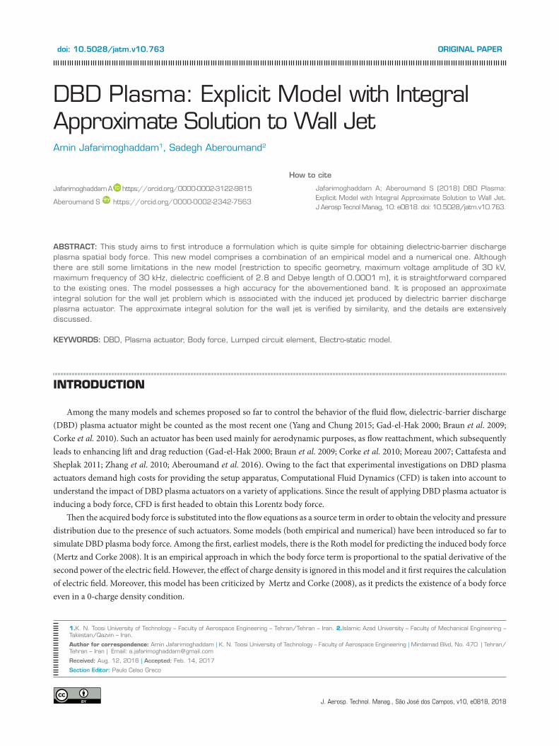
These factors are well-discussed in Mertz (2010). In the present paper, Eqs. 4 to 6 are solved using 2nd-order Runge-Kutta. Then, Eq. 1 are solved by the classical Gauss-Seidel explicit algorithm for spatial-time re-corrected conditions. Finally, the obtained spatial and steady body force was substituted into Navier-Stokes equations as the source term to validate the model with the previous experimental report of Debiasi and Jiun-Ming (2011). The schematics of the model is drawn in Fig. 1.
Figure 1. Engaged equations for the Lumped Circuit Element Electro-Static Model (Mertz 2010).
“Virtual” ElectrodeExposed Electrode
ExperimentModi�ed lumped circuit element
Velocity (m/s)0
0
1
2
3
4
5
6
7
8× 10⁻³
0.5 1 4 4.5 51.5 2 2.5 3 3.5
Y-D
irec
tion
(m)
modeL VaLidationJust as our previous study (Aberoumand et al. 2016), we used vorticity-stream function numerical approach for simulating
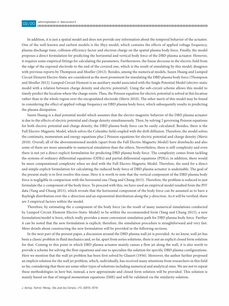
the effect of DBD plasma body force on velocity distribution. The discretization methodology for the body force based equations are the same as our previous paper (see Aberoumand et al. 2016). A comparison between experimental measurements reported by Debiasi and Jiun-Ming (2011) — at the threshold voltage of 12 kV, 25,000 Hz for the applied voltage frequency, Kapton as the dielectric material and the specific geometries used in the experiment — and the present numerical simulation is shown in Fig. 2. It indicates that the simulated plasma agrees with the experiment. In this case, Debye length was chosen to be 0.00001 based on the previous research by Ibrahim and Skote (2014).
Figure 2. Comparison between experimental results by Debiasi and Jiun-Ming (2011) and numerical simulation.
J. Aerosp. Technol. Manag., São José dos Campos, v10, e0818, 2018
DBD Plasma: Explicit Model with Integral Approximate Solution to Wall Jet xx/xx05/20
impLementation of Lumped CirCuit eLement eLeCtro-StatiC modeL for a Variety of dieLeCtriC-Barrier diSCharge pLaSma ConfigurationS
Here, simulating the DBD plasma body force via Lumped Circuit Element Electro-Static Model is continued for many actuator configurations. The applied configurations changed with changing the voltage amplitude, voltage frequency, dielectric coefficient and Debye length. Although the changing band for the abovementioned factors is vast enough to include a variety of DBD plasma configurations, we cannot simply proceed with applying different electrode lengths as well as different dielectric thicknesses. Basically, the specific hurdles of Lumped Circuit Element Electro-Static Model cause this limitation to arise.
The hurdles are mainly due to the fact that, to proceed with DBD plasma body force simulation by Lumped Circuit Element Electro-Static Model, we primary need some empirical values/factors. We followed the guidelines provided by Mertz (2010); thus the critical voltage was set to be 1 kV and the increase in sweep velocity was assumed to be 10 m/s / kV
together with the
assumption of a sine wave threshold voltage. Nevertheless, it would be doubtful to relate such empirical factors to any type of actuator geometries or fluid flow conditions. In the close future, authors will resolve this limitation from the upcoming formulation by proposing a more general (naturally, not free from empirical data) correlation.
propoSing the formuLation and diSCuSSionFollowing our previous discussion, we again insist that the y-component of the DBD plasma body force is negligible compared
to the x-component body force. Further based on a previous study (Yang and Chung 2015), the horizontal component of the body force can be expressed as:
where a, b and c are constant factors relating to the actuator configuration.Here, it is assumed that each result by Lumped Circuit Element Electro-Static Model corresponds to the certain values of a,
b and c. Applying Advanced Least Square Technique (Jafarimoghaddam et al. 2016; Jafarimoghaddam and Aberoumand (2016a, 2016b, 2016c); Aberoumand et al. 2017; Aberoumand et al. 2016), the most suitable factors were identified for each case. By simply repeating this procedure for a variety of cases with different configurations, the following explicit formulation was achieved:
where D is the Debye length; V0 is the voltage amplitude of the threshold voltage; f is the voltage frequency; e is the dielectric coefficient. The above formulation is highly accurate and only falls within about 5% error with the acquired results from the Lumped
Circuit Element Electro-Static Model (average R-Square for each case is about 0.95). In Eq. 8, all the variables must be in SI scale, and subsequently the acquired body force will be expressed in N/m3 per unit.
It should be noted that the maximum extent of spatial body force in the x-direction as well as the maximum induced body force by the actuator have been controlled whilst the most fitted vertical extension of the body force, together with the total induced body force over the spatial domain, has been optimized for each case. After the corresponding factors for each case were obtained, a general optimization process was performed to functionalize the structure of factors on the basis of DBD plasma configuration.
The explicit form of the proposed model provides a more convenient way for DBD plasma simulation mainly in flow control applications. Limitations of the model must be also considered: both electrodes of the actuator have 0.5 in; vertical and horizontal distance between the electrodes is 0.003 in; the dielectric coefficient is up to 2.8; the maximum band for voltage amplitude is 30 kV; the maximum band for voltage frequency is 30 kHz; Debye length can be modeled up to 0.00001 m; the minimum voltage amplitude
(7)
(8)
J. Aerosp. Technol. Manag., São José dos Campos, v10, e0818, 2018
Jafarimoghaddam A, Aberoumand Sxx/xx06/20
required for plasma formation is considered to be 1 kV. Therefore, practically, there would be almost no body force for voltage amplitudes lower than 1 kV. This assumption is made just because the suitability has been proved previously by authors and some other researchers (see Mertz 2010). Further advancement is restricted because the engaged empirical factors are at least strongly reliant on geometrical factors of the actuator. We could proceed to obtain a more general formulation for including different actuator geometries by assuming the previous empirical factors for any case, but the outcome would not be highly reliable. Furthermore, it can be considered that the Lumped Circuit Element Electro-Static is just a model for simulating the DBD plasma body force and, more precisely, it does not contain the whole phenomena engaged with the plasma formation. For example, Electro-Static in overall is for modeling the cold plasma, which is mainly referred to the low-pressure plasma (atmospheric pressure). Actually, that is why we call it Electro-Static, because, in low pressure, the energy of electrons cannot be easily transferred to the neutral air, and so the temperature of ions is quite different than the air itself; subsequently, there is not a temperature equilibrium between plasma and air phases.
Therefore, because of low-working pressure, drift diffusion can be ignored with respect to the electro-static forces (columbic forces). As another example of assumptions within the Electro-Static models, the Debye length is based on assuming a working temperature for ions. In addition, 3 main time scales defined for plasma formation allow assuming that the actuator works in a quasi-steady mode and, moreover, for applying the acquired body force into the flow equations, one enjoys the benefit of continuous phase assumption (it is a normal assumption but still an assumption). Disclosing the many assumptions in plasma simulation mainly by this model (Lumped Circuit Element Electro-Static Model) is not within the scope of the present paper, but it is in Mertz (2010). Generally, it is mainly the mathematical convenience rather than the accuracy of the model which motivates researchers to apply it. Nonetheless, the outcome results by this model can be still reliable when the model is applied with whole considerations. By the way, here we have laid trust in the results of Lumped Circuit Element Electro-Static Model as it has been used by many researchers over the past decade. Then, by combining the results by this model with an empirical relation proposed in Yang and Chung (2015), a more general and straightforward model has been achieved. The outcome results by the presented model were compared to the ones by the Lumped Circuit Element Electro-Static Model. This comparison was done for different plasma configurations as shown in the figures provided.
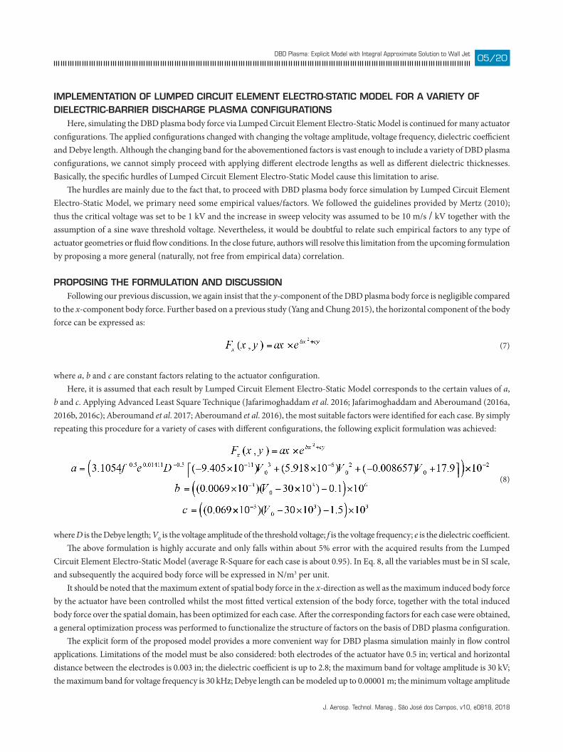
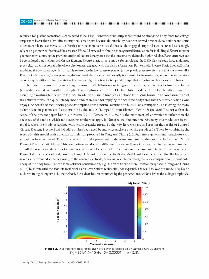
All the results are shown for the x-component body force, which is the main and the governing target of the preset study. Figure 3 shows the spatial body force by Lumped Circuit Element Electro-Static Model and it can be verified that the body force is vertically extended at the beginning of the covered electrode, decaying in a relatively large distance compared to the horizontal decay of the body force. For the same actuator configuration, Fig. 3 is fitted to the general relation proposed in Yang and Chung (2015) by minimizing the absolute total error using Least Square Techniques; consequently, the result follows our model (Eq. 8) and is shown in Fig. 4. Figure 5 shows the body force distribution estimated by the proposed model for 1 kV as the voltage amplitude.
Figure 3. X-component body force over the covered electrode by Lumped Circuit Element (V0 = 30 kV; f = 10 kHz; D = 0.00001 m; e = 2.8).
Body force (N/m3)
X-coordinate (mm)
Y-co
ordi
nate
(mm
)
4
3.5
3
2.5
2
1.5
1
0.5
00 1 2 3 4 5 6 7
0
500
1,000
1,500
2,000
2,500
3,000
3,500
J. Aerosp. Technol. Manag., São José dos Campos, v10, e0818, 2018
DBD Plasma: Explicit Model with Integral Approximate Solution to Wall Jet xx/xx07/20
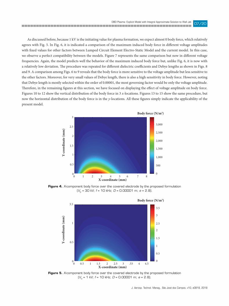
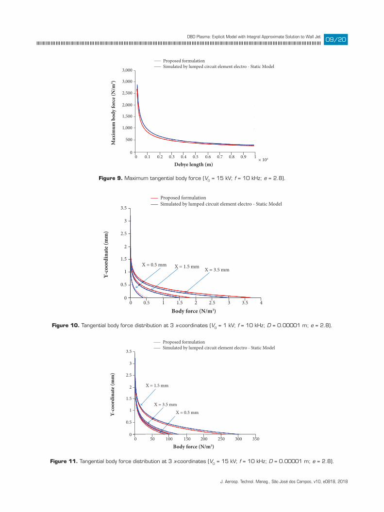
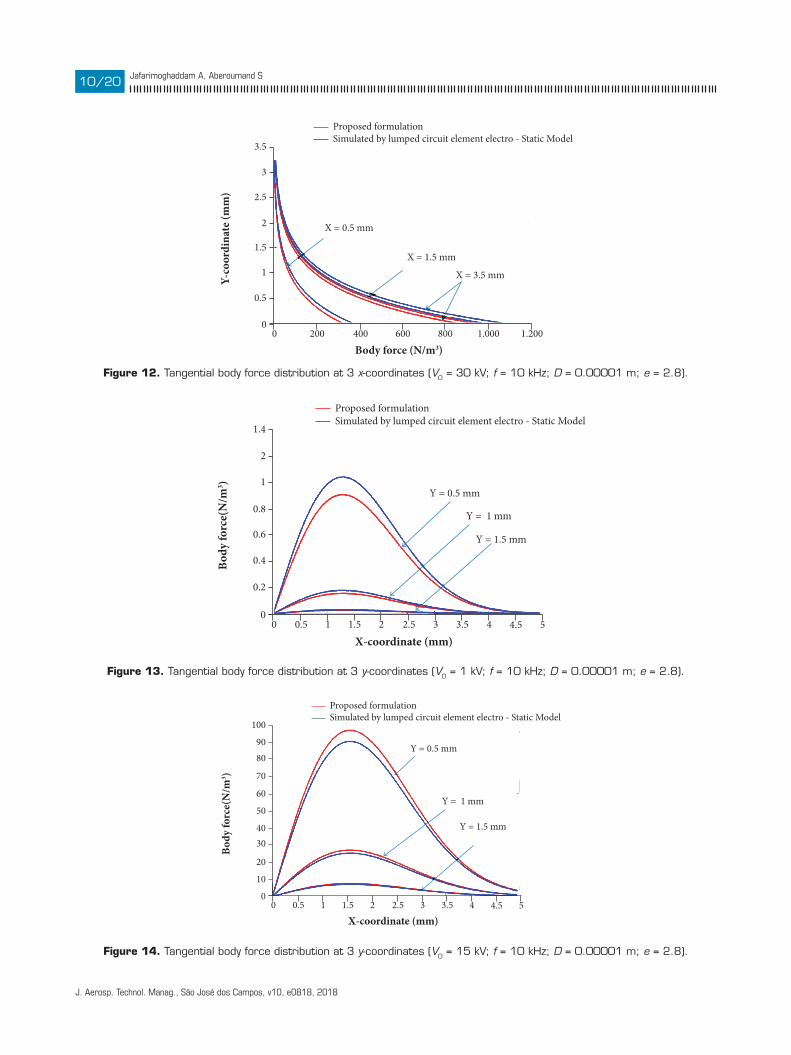
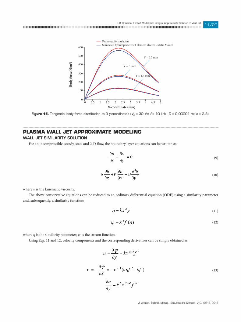
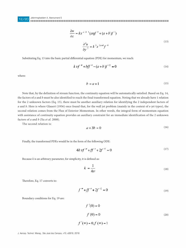
As discussed before, because 1 kV is the initiating value for plasma formation, we expect almost 0 body force, which relatively agrees with Fig. 5. In Fig. 6, it is indicated a comparison of the maximum induced body force in different voltage amplitudes with fixed values for other factors between Lumped Circuit Element Electro-Static Model and the current model. In this case, we observe a perfect compatibility between the models. Figure 7 represents the same comparison but now in different voltage frequencies. Again, the model predicts well the behavior of the maximum induced body force but, unlike Fig. 6, it is now with a relatively low deviation. The procedure was repeated for different dielectric coefficients and Debye lengths as shown in Figs. 8 and 9. A comparison among Figs. 6 to 9 reveals that the body force is more sensitive to the voltage amplitude but less sensitive to the other factors. Moreover, for very small values of Debye length, there is also a high sensitivity in body force. However, noting that Debye length is mostly selected within the order of 0.00001, the most governing factor would be only the voltage amplitude. Therefore, in the remaining figures at this section, we have focused on displaying the effect of voltage amplitude on body force. Figures 10 to 12 show the vertical distribution of the body force in 3 x-locations. Figures 13 to 15 show the same procedure, but now the horizontal distribution of the body force is in the y-locations. All these figures simply indicate the applicability of the present model.
Figure 4. X-component body force over the covered electrode by the proposed formulation (V0 = 30 kV; f = 10 kHz; D = 0.00001 m; e = 2.8).
Figure 5. X-component body force over the covered electrode by the proposed formulation (V0 = 1 kV; f = 10 kHz; D = 0.00001 m; e = 2.8).
Body force (N/m3)
X-coordinate (mm)
Y-co
ordi
nate
(mm
)
3
2.5
2
1.5
1
0.5
00 1 2 3 4 5 6 7 8
0
500
1,000
1,500
2,000
2,500
3,000
Body force (N/m3)
X-coordinate (mm)
Y-co
ordi
nate
(mm
)
3.5
1
0.5
00 0.5 1 1.5 2 2.5 3 .53 4 4.5
0
0.5
1
1.5
2
2.5
3.5
3
J. Aerosp. Technol. Manag., São José dos Campos, v10, e0818, 2018
Jafarimoghaddam A, Aberoumand Sxx/xx08/20
Proposed formulationSimulated by lumped circuit element electro - Static Model
Peal voltage amplitude (V)0
0
3,500
3,000
2,500
2,000
1,500
1,000
500
0.5 1 1.5 2 2.5 3× 10⁴
Max
imum
hor
izon
tal b
ody
forc
e (N
/m3 )
Proposed formulationSimulated by lumped circuit element electro - Static Model
Voltage frequency (Hz)0
920
990
980
970
960
950
940
930
0.5 1 1.5 2 2.5 3× 10⁴
Max
imum
hor
izon
tal b
ody
forc
e (N
/m3 )
Proposed formulationSimulated by lumped circuit element electro - Static Model
Dielectric coe�cient0
840
900
890
880
870
860
850
5 10 15 20 25 30
Max
imum
bod
y fo
rce
(N/m
3 )
Figure 6. Maximum tangential body force (f = 10 kHz; D = 0.00001 m; e = 2.8).
Figure 7. Maximum tangential body force (V0 = 15 kV; D = 0.00001 m; e = 2.8).
Figure 8. Maximum tangential body force (V0 = 15 kV; f = 10 kHz; D = 0.00001 m).
J. Aerosp. Technol. Manag., São José dos Campos, v10, e0818, 2018
DBD Plasma: Explicit Model with Integral Approximate Solution to Wall Jet xx/xx09/20
Proposed formulationSimulated by lumped circuit element electro - Static Model
Debye length (m)0
0
3,000
3,000
2,500
2,000
1,500
1,000
500
0.1 0.2 0.3 0.4 0.5 0.6 0.7 0.8 0.9 1 × 10⁴
Max
imum
bod
y fo
rce
(N/m
3 )
Proposed formulationSimulated by lumped circuit element electro - Static Model
Body force (N/m3)0
0
3.5
3
2.5
2
1.5
1
0.5
0.5
X = 0.5 mm X = 1.5 mm X = 3.5 mm
1 1.5 2 2.5 3 3.5 4
Y-co
ordi
nate
(mm
)
Proposed formulationSimulated by lumped circuit element electro - Static Model
Body force (N/m3)0
0
3.5
3
2.5
2
1.5
1
0.5
50
X = 0.5 mm
X = 1.5 mm
X = 3.5 mm
100 150 200 250 300 350
Y-co
ordi
nate
(mm
)
Figure 9. Maximum tangential body force (V0 = 15 kV; f = 10 kHz; e = 2.8).
Figure 10. Tangential body force distribution at 3 x-coordinates (V0 = 1 kV; f = 10 kHz; D = 0.00001 m; e = 2.8).
Figure 11. Tangential body force distribution at 3 x-coordinates (V0 = 15 kV; f = 10 kHz; D = 0.00001 m; e = 2.8).
J. Aerosp. Technol. Manag., São José dos Campos, v10, e0818, 2018
Jafarimoghaddam A, Aberoumand Sxx/xx10/20
Proposed formulationSimulated by lumped circuit element electro - Static Model
Body force (N/m3)0
0
3.5
3
2.5
2
1.5
1
0.5
200
X = 0.5 mm
X = 1.5 mm
X = 3.5 mm
400 600 800 1.000 1.200
Y-co
ordi
nate
(mm
)
Proposed formulationSimulated by lumped circuit element electro - Static Model
X-coordinate (mm)0
0
1.4
2
1
0.8
0.6
0.4
0.2
0.5 1 1.5 2 2.5 3 3.5 4 4.5 5
Y = 0.5 mm
Y = 1.5 mm
Y = 1 mm
Body
forc
e(N
/m3 )
Proposed formulationSimulated by lumped circuit element electro - Static Model
X-coordinate (mm)0
0
100
9080
70
60
40
50
30
10
20
0.5 1 1.5 2 2.5 3 3.5 4 4.5 5
Y = 0.5 mm
Y = 1.5 mm
Y = 1 mm
Body
forc
e(N
/m3 )
Figure 12. Tangential body force distribution at 3 x-coordinates (V0 = 30 kV; f = 10 kHz; D = 0.00001 m; e = 2.8).
Figure 13. Tangential body force distribution at 3 y-coordinates (V0 = 1 kV; f = 10 kHz; D = 0.00001 m; e = 2.8).
Figure 14. Tangential body force distribution at 3 y-coordinates (V0 = 15 kV; f = 10 kHz; D = 0.00001 m; e = 2.8).
J. Aerosp. Technol. Manag., São José dos Campos, v10, e0818, 2018
DBD Plasma: Explicit Model with Integral Approximate Solution to Wall Jet xx/xx11/20
Proposed formulationSimulated by lumped circuit element electro - Static Model
X-coordinate (mm)0
0
600
500
400
300
200
100
0.5 1 1.5 2 2.5 3 3.5 4 4.5 5
Y = 0.5 mm
Y = 1.5 mm
Y = 1 mmBo
dy fo
rce(
N/m
3 )
Figure 15. Tangential body force distribution at 3 y-coordinates (V0 = 30 kV; f = 10 kHz; D = 0.00001 m; e = 2.8).
PLASMA WALL JET APPROXIMATE MODELINGWaLL Jet SimiLarity SoLution
For an incompressible, steady-state and 2-D flow, the boundary layer equations can be written as:
where υ is the kinematic viscosity.The above conservative equations can be reduced to an ordinary differential equation (ODE) using a similarity parameter
and, subsequently, a similarity function:
where η is the similarity parameter; ψ is the stream function.Using Eqs. 11 and 12, velocity components and the corresponding derivatives can be simply obtained as:
(9)
(10)
(11)
(12)
(13)
J. Aerosp. Technol. Manag., São José dos Campos, v10, e0818, 2018
Jafarimoghaddam A, Aberoumand Sxx/xx12/20
Substituting Eq. 13 into the basic partial differential equation (PDE) for momentum, we reach:
where:
Note that, by the definition of stream function, the continuity equation will be automatically satisfied. Based on Eq. 14, the factors of a and b must be also identified to reach the final transformed equation. Noting that we already have 1 relation for the 2 unknown factors (Eq. 15), there must be another auxiliary relation for identifying the 2 independent factors of a and b. Here is where Glauert (1956) once found that, for the wall jet problem (mainly in the context of e-jet types), the second relation comes from the Flux of Exterior Momentum. In other words, the integral form of momentum equation with assistance of continuity equation provides an auxiliary constraint for an immediate identification of the 2 unknown factors of a and b (Xu et al. 2008).
The second relation is:
Finally, the transformed PDEs would be in the form of the following ODE:
Because k is an arbitrary parameter, for simplicity, it is defined as:
Therefore, Eq. 17 converts to:
Boundary conditions for Eq. 19 are:
(13)
(14)
(15)
(16)
(17)
(18)
(19)
(20)
J. Aerosp. Technol. Manag., São José dos Campos, v10, e0818, 2018
DBD Plasma: Explicit Model with Integral Approximate Solution to Wall Jet xx/xx13/20
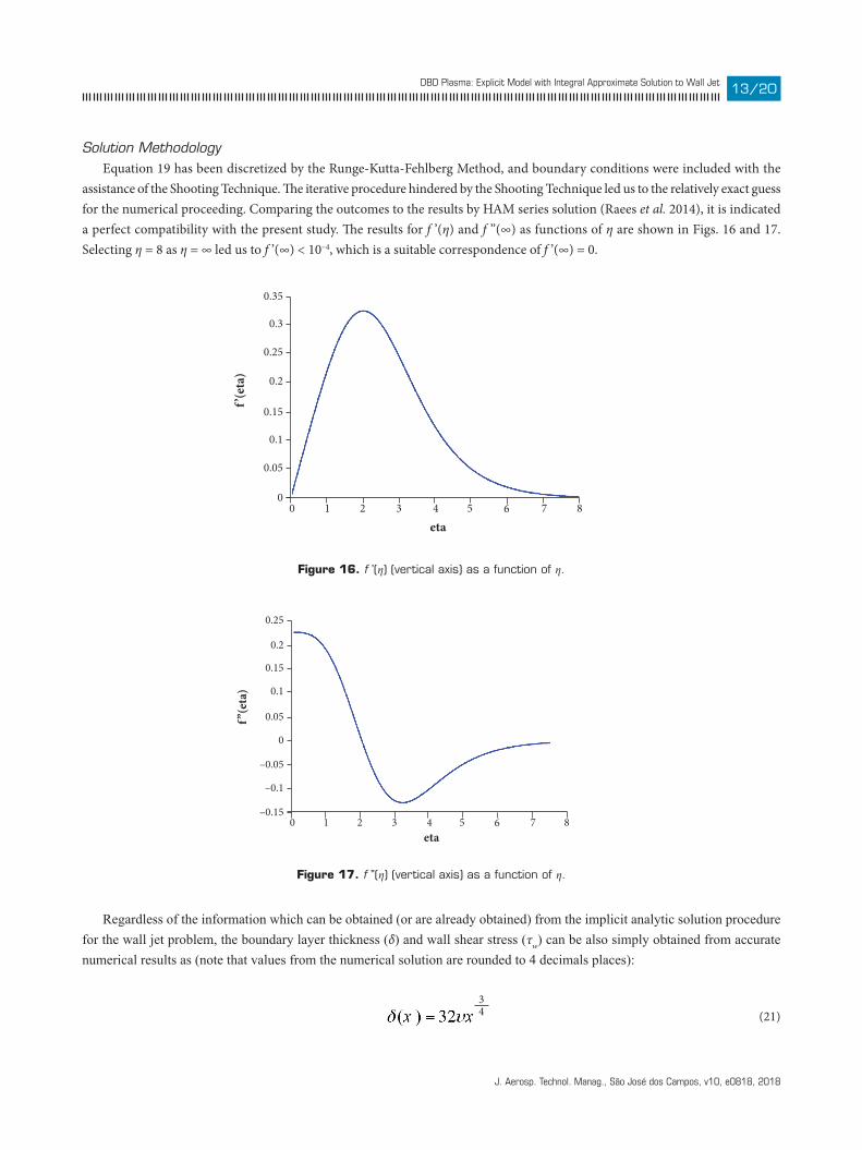
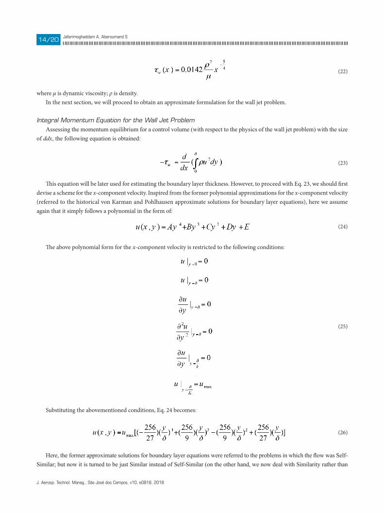
Solution MethodologyEquation 19 has been discretized by the Runge-Kutta-Fehlberg Method, and boundary conditions were included with the
assistance of the Shooting Technique. The iterative procedure hindered by the Shooting Technique led us to the relatively exact guess for the numerical proceeding. Comparing the outcomes to the results by HAM series solution (Raees et al. 2014), it is indicated a perfect compatibility with the present study. The results for f ’(η) and f ’’(∞) as functions of η are shown in Figs. 16 and 17. Selecting η = 8 as η = ∞ led us to f ’(∞) < 10–4, which is a suitable correspondence of f ’(∞) = 0.
00
0.35
0.3
0.25
0.2
0.15
0.1
0.05
1 2 3
f’(eta)
eta4 5 6 7 8
0–0.15
0.25
0.2
0.15
0.1
0.05
0
–0.05
–0.1
1 2 3 4 5 6 7 8
f’’(eta)
eta
Figure 16. f ’(η) (vertical axis) as a function of η.
Figure 17. f ’’(η) (vertical axis) as a function of η.
Regardless of the information which can be obtained (or are already obtained) from the implicit analytic solution procedure for the wall jet problem, the boundary layer thickness (δ) and wall shear stress (τw) can be also simply obtained from accurate numerical results as (note that values from the numerical solution are rounded to 4 decimals places):
(21)34
J. Aerosp. Technol. Manag., São José dos Campos, v10, e0818, 2018
Jafarimoghaddam A, Aberoumand Sxx/xx14/20
where μ is dynamic viscosity; ρ is density.In the next section, we will proceed to obtain an approximate formulation for the wall jet problem.
Integral Momentum Equation for the Wall Jet ProblemAssessing the momentum equilibrium for a control volume (with respect to the physics of the wall jet problem) with the size
of ddx, the following equation is obtained:
This equation will be later used for estimating the boundary layer thickness. However, to proceed with Eq. 23, we should first devise a scheme for the x-component velocity. Inspired from the former polynomial approximations for the x-component velocity (referred to the historical von Karman and Pohlhausen approximate solutions for boundary layer equations), here we assume again that it simply follows a polynomial in the form of:
The above polynomial form for the x-component velocity is restricted to the following conditions:
Substituting the abovementioned conditions, Eq. 24 becomes:
Here, the former approximate solutions for boundary layer equations were referred to the problems in which the flow was Self-Similar; but now it is turned to be just Similar instead of Self-Similar (on the other hand, we now deal with Similarity rather than
(22)
(23)
(24)
(26)
(25)
J. Aerosp. Technol. Manag., São José dos Campos, v10, e0818, 2018
DBD Plasma: Explicit Model with Integral Approximate Solution to Wall Jet xx/xx15/20
Self-Similarity). Therefore, assuming an unknown stretching/shrinking x-dependent function (Umax) seems to be necessary for proceeding with approximate solutions for Similar flows. Now the problem is just to identify Umax as a function of x (after that, boundary layer thickness can be easily achieved with respect to IME). For this, one can simply assume that Umax follows the following relation:
In Eq. 27, A and n are factors corresponded to the similarity solution. Therefore, it is easily calculated that: A = 08086υ–1/3 and n = –2/3 .
Substituting Eq. 27 into Eq. 26 and then using Eq. 26 in Eq. 23 (IME), we will have:
where:
Finally, the boundary layer thickness can be simply achieved as:
Moreover, wall shear stress will be obtained as:
Note that, in the present study, we aim to propose an approximate closed form solution for the wall jet problem instead of a compact scheme for the solution of wall jet just by IME means. In our close future studies, we will proceed with the solution of wall jet problem just by IME means, absolutely independent of similarity results (it is still in progress by the authors).
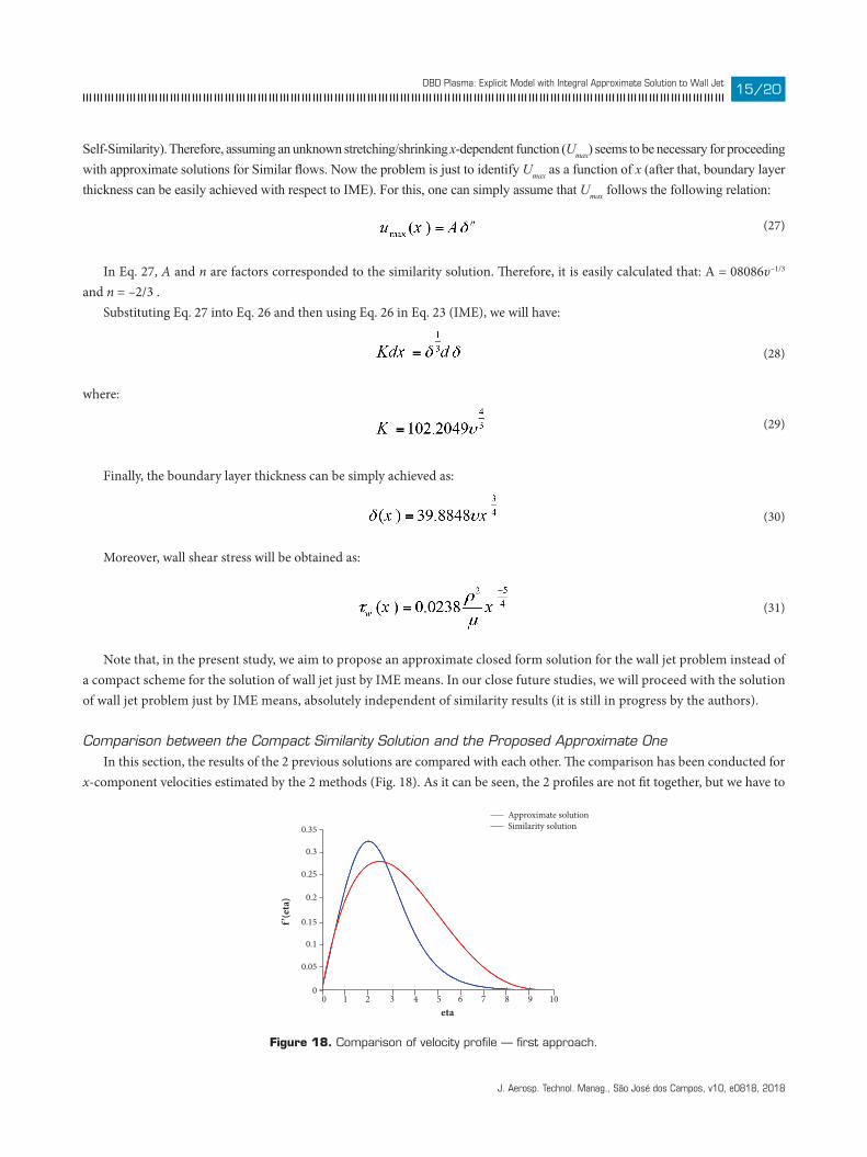
Comparison between the Compact Similarity Solution and the Proposed Approximate OneIn this section, the results of the 2 previous solutions are compared with each other. The comparison has been conducted for
x-component velocities estimated by the 2 methods (Fig. 18). As it can be seen, the 2 profiles are not fit together, but we have to
Figure 18. Comparison of velocity profile — first approach.
Approximate solutionSimilarity solution
00
0.35
0.3
0.25
0.2
0.15
0.1
0.05
1 32 54 6 7 8 9 10
f’(eta)
eta
(27)
(28)
(29)
(30)
(31)
J. Aerosp. Technol. Manag., São José dos Campos, v10, e0818, 2018
Jafarimoghaddam A, Aberoumand Sxx/xx16/20
note that the boundary layer thickness and also wall shear stress have relatively better approximations by this method. Overall, boundary layer thickness has the best fit with the similarity solution by this method while wall shear stress possesses a lower accuracy with the similarity solution. However, the velocity profile estimated by this method is really weak to predict the velocity profile by similarity solution. Therefore, in the next section, the velocity profile proposed by IME solution will receive a slight modification, but at the cost of losing accuracy for predicting wall shear stress.
Modified Approximate SolutionIn this section, we will modify the former proposed profile for the x-component velocity. However, by doing this, we lose the
accuracy for wall shear stress estimation. Reminding our purpose in the present study, this modification can really be counted as a step for achieving a relatively closed form solution for the wall jet problem. Consider Eq. 27 for estimating Umax but now in the form of:
where a is an arbitrary parameter for including our modification. It can be proved that, if a is selected to be 1.3414, the boundary layer thickness will be automatically adapted to the similarity
solution and, further, the maximum jet velocity and its location will be also adapted to the results of similarity solution. Nevertheless, as mentioned before, wall shear stress will greatly lose its accuracy compared to that of the similarity solution. Here, just the results for velocity profile are validated by those of similarity solution, and details about the new polynomial form for velocity and manipulation of wall shear stress will be included in the last section of the present paper.
a note regarding the dieLeCtriC-Barrier diSCharge pLaSma inCLuSion and diSCuSSionIn this section, we will discuss about specializing the results of wall jet solution for specific DBD plasma configuration. It is
obvious that the wall jet problem is solved regardless of the physical cause of the jet. According to the results of similarity solution and the proposed approximate solutions (both the former and the modified one), by passing through the jet, boundary layer thickness grows from 0 to infinity and, inversely, maximum jet velocity decays from infinity to 0. In the case of wall jet produced as the result of DBD plasma actuator, the maximum induced velocity is restricted to the actuator configuration, which cannot be infinity at the beginning of the jet. Therefore, there must be a location after the jet origin (a particular one) where the solution of DBD plasma wall jet starts from. This location must be dependent on the actuator configuration and on the closed-form body force proposed by the present research (Eq. 8). In our close future studies, we will also propose such a relation with respect to our new proposed model for DBD plasma body force.
Summarizing the neW aChieVementS By the preSent StudyDBD plasma body force was explicitly formulated as:
In Eq. 33, all the variables are in the SI unit. Moreover, the model is restricted to the specific geometry; furthermore, there are bands for variables within the proposed model.
(32)
(33)6
J. Aerosp. Technol. Manag., São José dos Campos, v10, e0818, 2018
DBD Plasma: Explicit Model with Integral Approximate Solution to Wall Jet xx/xx17/20
Wall Jet Problem — First Approximate SolutionResults of similarity solution were combined with the IME analysis; finally, by considering a scheme for the x-component
velocity, an approximate close form solution was proposed as:
In Eq. 34, δ was obtained as:
and umax was achieved as:
Finally, wall shear stress was formulated as:
Compared to the results by similarity solution:
Except for wall shear stress, boundary layer thickness and maximum x-velocity are well-approximated. But here we note again that the x-velocity profile by this approximation is not suitably corresponded to that of the similarity solution (Fig. 18).
Modified Approximate Solution for the Wall Jet ProblemFor this, the former proposed model was modified by introducing an auxiliary factor; finally, the proposed model became in
the following form:
But now, δ, umax and τw are:
(34)
(35)
(36)
(37)
(40)
(39)
(38)
J. Aerosp. Technol. Manag., São José dos Campos, v10, e0818, 2018
Jafarimoghaddam A, Aberoumand Sxx/xx18/20
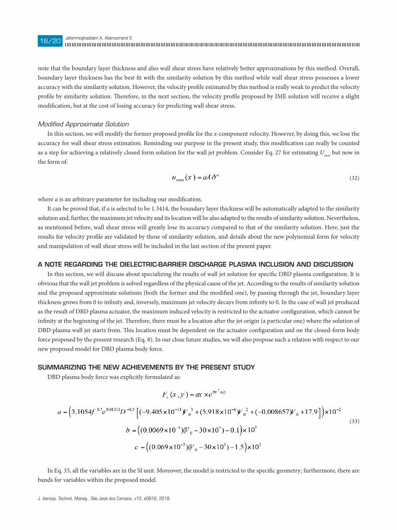
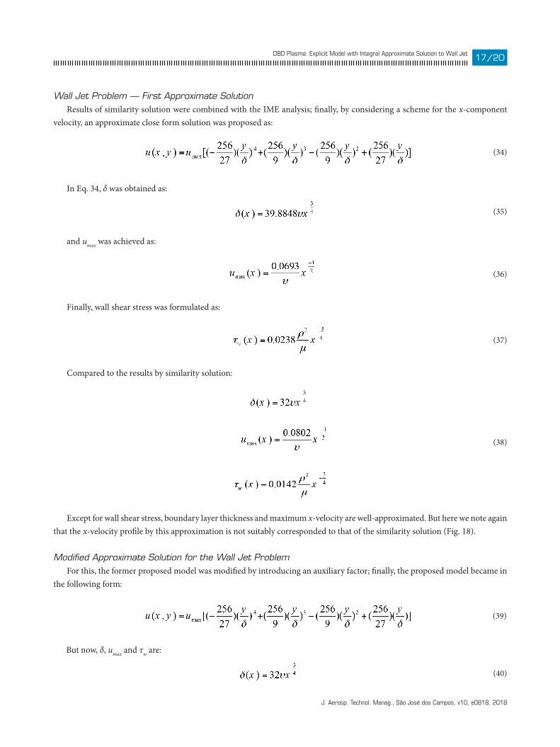
Boundary layer thickness and maximum x-velocity are excellently approximated by this model and, further, the proposed formulation for the x-component velocity profile (Eq. 39) is almost corresponded to that of the similarity solution (Fig. 19). Although the proposed approximate closed form solution (Eq. 39) might be suitable for engineering applications, mainly because the relation is closed form and straightforward, here we are not allowed to use its result for wall shear stress because it is not really corresponded to that of the similarity solution. Then we recommend using the result of the similarity solution instead. The proposed approximate solutions fully satisfy the IME and further they are completely compatible to the nature of the problem, but in different scales. Finally, based on the formulation of maximum x-velocity, by empirically estimating the maximum x-component velocity induced by the DBD plasma body force, it will be easy to identify the location where the plasma jet begins. However, as mentioned, it is still in progress to determine this location independently of the experimental results.
Figure 19. Comparison of velocity profile — second approach.
CONCLUSION
In the present study, 2 main goals have been targeted. The first was to introduce an explicit and straightforward formulation for DBD plasma body force. For this, we showed that the proposed formulation (model) agrees well with the results by Lumped Circuit Element Electro-Static Model. Secondly, we proceeded with proposing a new approximate model for the wall jet problem. The model chiefly comprised a combination of similarity solution and IME analysis. We further showed that the first approximate model was not appropriate as it could not predict the behavior of the x-component velocity especially at the infinity (where the flow is supposed to express an exponential trend). However, the second modified approximate solution was really appropriate, especially for engineering applications, but there was just 1 major drawback in which the second model could not almost predict the wall shear stress. For this, we recommend using the results via similarity solution. Finally, as the main purpose of the second part of the present research, we aimed mainly to propose a scheme to obtain approximate closed form solution and not to derive the solution just by IME analysis. Therefore, some further researches are still needed to resolve the drawbacks within the present study.
(40)
Modi�ed approximate solutionSimilarity solution
00
0.35
0.3
0.25
0.2
0.15
0.1
0.05
1 32 54 6 7 8
f’(eta)
eta
J. Aerosp. Technol. Manag., São José dos Campos, v10, e0818, 2018
DBD Plasma: Explicit Model with Integral Approximate Solution to Wall Jet xx/xx19/20
AUTHOR’S CONTRIBUTION
Conceptualization, Jafarimoghaddam A; Methodology, Jafarimoghaddam A; Investigation, Jafarimoghaddam A and Aberoumand S; Writing – Original Draft, Jafarimoghaddam A and Aberoumand S; Writing – Review & Editing, Jafarimoghaddam A and Aberoumand S; Resources, Jafarimoghaddam A and Aberoumand S; Supervision, Jafarimoghaddam A.
REFERENCESAberoumand S, Jafarimoghaddam A, Aberoumand H (2016) Numerical investigation on the impact of DBD plasma actuators on temperature enhancement in the channel flow. Heat Trans Asian Res 46(5):497-510. doi: 10.1002/htj.21227
Aberoumand S, Jafarimoghaddam A, Aberoumand H, Javaherdeh K (2017) On the viscosity of Ag/oil based nanofluids: a correlation. Heat Trans Asian Res 46(1):18-28. doi: 10.1002/htj.21193
Aberoumand S, Jafarimoghaddam A, Moravej M, Aberoumand H, Javaherdeh K (2016) Experimental study on the rheological behavior of silver-heat transfer oil nanofluid and suggesting two empirical based correlations for thermal conductivity and viscosity of oil based nanofluids. Appl Therm Eng 101:362-372. doi: 10.1016/j.applthermaleng.2016.01.148
Braun EM, Lu FK, Wilson DR (2009) Experimental research in aerodynamic control with electric and electromagnetic fields. Progr Aero Sci 45(1-3):30-49. doi: 10.1016/j.paerosci.2008.10.003
Cattafesta LN, Sheplak M (2011) Actuators for active flow control. Ann Rev Fluid Mech 43:247-272. doi 10.1146/annurev-fluid-122109-160634
Corke TC, Enloe CL, Wilkinson SP (2010) Dielectric barrier discharge plasma actuators for flow control. Ann Rev Fluid Mech 42:505-529. doi: 10.1146/annurev-fluid-121108-145550
Debiasi M, Jiun-Ming L (2011) Experimental study of a DBD-Plasma driven channel flow. Proceedings of the 49th AIAA Aerospace Sciences Meeting including the New Horizons Forum and Aerospace Exposition, Aerospace Sciences Meetings; Orlando, USA.
Gad-el-Hak M (2000) Flow control: passive, active, and reactive flow management. Cambridge: Cambridge University Press.
Glauert MB (1956) The wall jet. J Fluid Mech 1:625-643. doi: 10.1017/S002211205600041X
Ibrahim IH, Skote M (2014) Simulating plasma actuators in a channel flow configuration by utilizing the modified Suzen-Huang model. Comput Fluid 99:144-155. doi: 10.1016/j.compfluid.2014.04.017
Jafarimoghaddam A, Aberoumand S (2016a) An empirical investigation on Cu/ethylene glycol nanofluid through a concentric annular tube and proposing a correlation for predicting Nusselt number. Alexandria Engineering Journal 55:1047-1052. doi: 10.1016/j.aej.2016.03.005
Jafarimoghaddam A, Aberoumand S (2016b) Exact approximations for skin friction coefficient and convective heat transfer coefficient for a class of power law fluids flow over a semi-infinite plate: Results from similarity solutions. Eng Sci Tech Int J 20(3):1115-1121. doi: 10.1016/j.jestch.2016.10.020
Jafarimoghaddam A, Aberoumand S (2016c) Introducing an optimized airfoil shape using panel method: a short report. Eur J Adv Eng Tech 3(7):47-52.
Jafarimoghaddam A, Aberoumand S, Aberoumand H, Javaherdeh K (2016) Experimental study on Cu/oil nanofluids through concentric annular tube: a correlation. Heat Trans Asian Res 46(3):251-260. doi: 10.1002/htj.21210
Mertz BE (2010) Refinement, validation, and implementation of Lumped Circuit Element Model for single dielectric barrier discharge plasma actuators (PhD thesis). Notre Dame: University of Notre Dame.
Mertz BE, Corke TC (2008) Time-dependent dielectric barrier dishcharge plasma actuator modeling. Proceedings of the 47th AIAA Aerospace Sciences Meeting; Orlando, USA.
Moreau E (2007) Airflow control by non-thermal plasma actuators. J Phys D Appl Phys 40(3):605-636. doi: 10.1088/0022-3727/40/3/S01
Orlov DM (2006) Modelling and simulation of single dielectric barrier discharge plasma actuators [Master’s thesis]. Notre Dame: University of Notre Dame.
Raees A, Xu H, Raees-ul-Haq M (2014) Explicit solutions of wall jet flow subject to a convective boundary condition. Bound Value Probl 2014:163. doi: 10.1186/1687-2770-2014-163
Thompson RJ, Moeller TM (2010) Numerical investigations of plasma actuator Lorentz body forces. Proceedings of the 50th AIAA Aerospace Sciences Meeting including the New Horizons Forum and Aerospace Exposition; Nashville, USA.
J. Aerosp. Technol. Manag., São José dos Campos, v10, e0818, 2018
Jafarimoghaddam A, Aberoumand Sxx/xx20/20
Xu H, Liao SJ, Wu GX (2008) A family of new solutions on the wall jet. European Journal of Mechanics - B/Fluids 27(3):322-334. doi: 10.1016/j.euromechflu.2007.07.002
Yang Q, Chung YM (2015) Numerical study of reducing turbulent skin-friction drag using DBD plasma actuators. Proceedings of the European Drag Reduction and Flow Control Meeting (EDRFCM 2015); Cambridge, UK.
Zhang PF, Wang JJ, Feng LH, Wang GB (2010) Experimental study of plasma flow control on highly swept delta wing. AIAA J 48(1):249-252. doi: 10.2514/1.40274