Embed Size (px)
Citation preview
Yiping Feng and Eliazar [email protected]@slac.stanford.edu
LUSI DOE Review Aug. 20, 2008 DCO Design, Baseline, & Risks p. 1
Diagnostics & Common Optics Diagnostics & Common Optics Design, Baseline, & RisksDesign, Baseline, & Risks
Yiping Feng – DCO Lead ScientistEliazar Ortiz – DCO Lead Engineer
LUSI CD-2 Lehman ReviewAugust 20, 2008
Lead Engineer: Eliazar Ortiz Mechanical Engineer: Marc Campell Mechanical Engineer: Nadine Kurita Design Engineer: Rick JacksonDesigner: Don ArnettDesigner: Ben Bigornia
Yiping Feng and Eliazar [email protected]@slac.stanford.edu
LUSI DOE Review Aug. 20, 2008 DCO Design, Baseline, & Risks p. 2
Outline
Physics requirementsSafetyComponents distributionEngineering/design statusValue engineering/managementBasis of estimateProcurement strategyCosts & scheduleCritical pathRisk analysisSummary
Yiping Feng and Eliazar [email protected]@slac.stanford.edu
LUSI DOE Review Aug. 20, 2008 DCO Design, Baseline, & Risks p. 3
DCO Team
Specifications and component concept developed by DCO scientific/technical team
Yiping Feng, DCO lead scientistInstrument liaisons & DCO scientists
David Fritz, XPP instr., attenuator, harmonic rejection mirrorsMarc Messerschmidt, XPP instr.Sébastien Boutet, CXI instr., slits system, pulse pickerAymeric Robert, XCS instr., focusing lens, offset monochromator
Niels van Bakel, X-ray detectors supportGunther Haller/Dieter Freytag, EE support
Components engineered byDCO engineering team
Eliazar Ortiz –
Lead EngineerMarc Campell –
Mechanical EngineerNadine Kurita –
Mechanical EngineerRick Jackson –
Design EngineerDon Arnett –
DesignerBen Bigornia –
Designer
Yiping Feng and Eliazar [email protected]@slac.stanford.edu
LUSI DOE Review Aug. 20, 2008 DCO Design, Baseline, & Risks p. 4
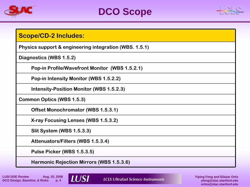
DCO Scope
Scope/CD-2 Includes:
Physics support & engineering integration (WBS. 1.5.1)
Diagnostics (WBS 1.5.2)
Pop-in Profile/Wavefront Monitor (WBS 1.5.2.1)
Pop-in Intensity Monitor (WBS 1.5.2.2)
Intensity-Position Monitor (WBS 1.5.2.3)
Common Optics (WBS 1.5.3)
Offset Monochromator (WBS 1.5.3.1)
X-ray Focusing Lenses (WBS 1.5.3.2)
Slit System (WBS 1.5.3.3)
Attenuators/Filters (WBS 1.5.3.4)
Pulse Picker (WBS 1.5.3.5)
Harmonic Rejection Mirrors (WBS 1.5.3.6)
Yiping Feng and Eliazar [email protected]@slac.stanford.edu
LUSI DOE Review Aug. 20, 2008 DCO Design, Baseline, & Risks p. 5
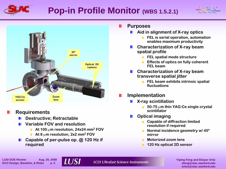
Pop-in Profile Monitor (WBS 1.5.2.1)
RequirementsDestructive; RetractableVariable FOV and resolution
At 100 μm resolution, 24x24 mm2
FOVAt 8 μm resolution, 2x2 mm2
FOV
Capable of per-pulse op. @ 120 Hz if required
YAG:Cescreen
45ºmirror
Optical 2D camera
Zoomlens
PurposesAid in alignment of X-ray optics
FEL is serial operation, automation enables maximum productivity
Characterization of X-ray beam spatial profile
FEL spatial mode structureEffects of optics on fully coherent FEL beam
Characterization of X-ray beam transverse spatial jitter
FEL beam exhibits intrinsic spatial fluctuations
ImplementationX-ray scintillation
50-75 μm thin YAG:Ce single crystal scintillator
Optical imagingCapable of
diffraction limited
resolution if requiredNormal incidence geometry w/ 45º
mirrorMotorized zoom lens120 Hz optical 2D sensor
Yiping Feng and Eliazar [email protected]@slac.stanford.edu
LUSI DOE Review Aug. 20, 2008 DCO Design, Baseline, & Risks p. 6
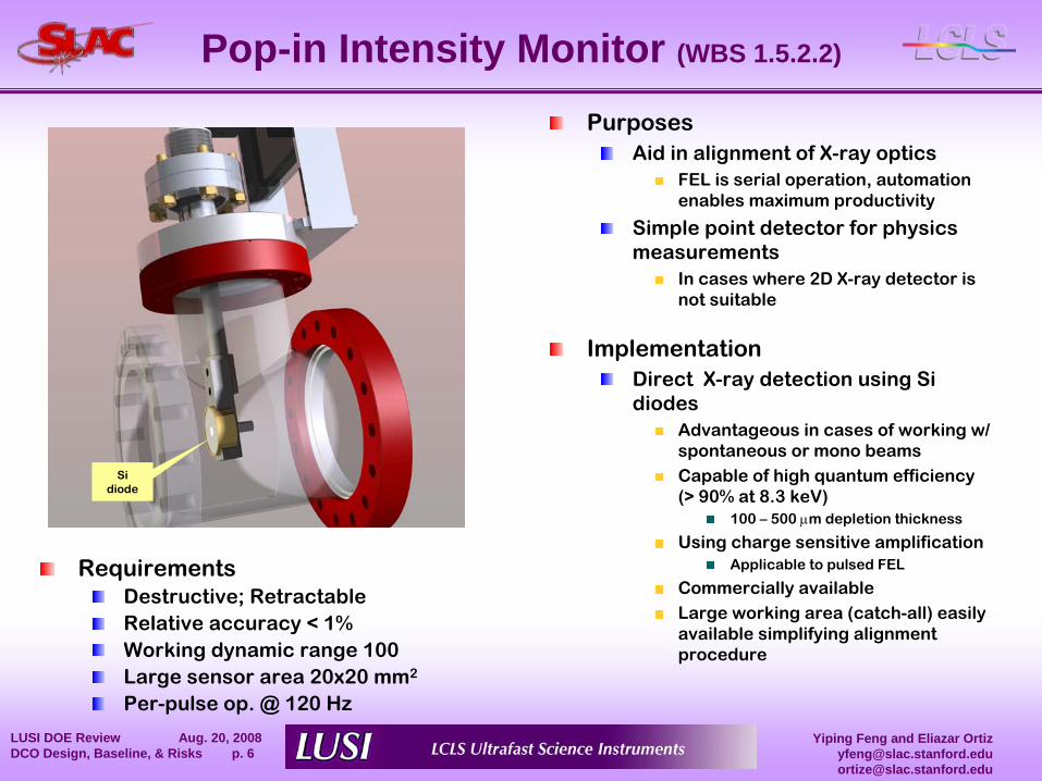
Pop-in Intensity Monitor (WBS 1.5.2.2)
RequirementsDestructive; RetractableRelative accuracy < 1%Working dynamic range 100Large sensor area 20x20 mm2
Per-pulse op. @ 120 Hz
Sidiode
PurposesAid in alignment of X-ray optics
FEL is serial operation, automation enables maximum productivity
Simple point detector for physics measurements
In cases where 2D X-ray detector is not suitable
ImplementationDirect X-ray detection using Si diodes
Advantageous in cases of working w/ spontaneous or mono beamsCapable of high quantum efficiency (> 90% at 8.3 keV)
100 –
500 μm depletion thickness
Using charge sensitive amplificationApplicable to pulsed FEL
Commercially availableLarge working area (catch-all) easily available simplifying alignment procedure
Yiping Feng and Eliazar [email protected]@slac.stanford.edu
LUSI DOE Review Aug. 20, 2008 DCO Design, Baseline, & Risks p. 7
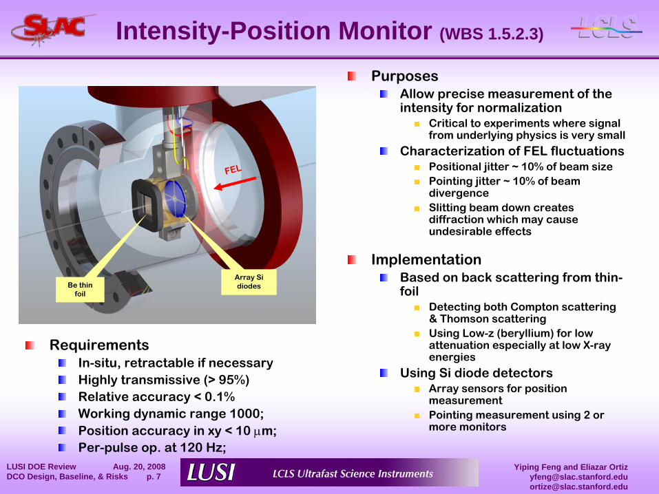
Be thin foil
Array Si diodes
Intensity-Position Monitor (WBS 1.5.2.3)
RequirementsIn-situ, retractable if necessaryHighly transmissive (> 95%)Relative accuracy < 0.1%Working dynamic range 1000;Position accuracy in xy < 10 μm;Per-pulse op. at 120 Hz;
FEL
PurposesAllow precise measurement of the intensity for normalization
Critical to experiments where signal from underlying physics is very small
Characterization of FEL fluctuationsPositional jitter ~ 10% of beam size Pointing jitter ~ 10% of beam divergenceSlitting beam down creates diffraction which may cause undesirable effects
ImplementationBased on back scattering from thin-
foil
Detecting both Compton scattering & Thomson scattering Using Low-z (beryllium) for low attenuation especially at low X-ray energies
Using Si diode detectorsArray sensors for position measurementPointing measurement using 2 or more monitors
Yiping Feng and Eliazar [email protected]@slac.stanford.edu
LUSI DOE Review Aug. 20, 2008 DCO Design, Baseline, & Risks p. 8
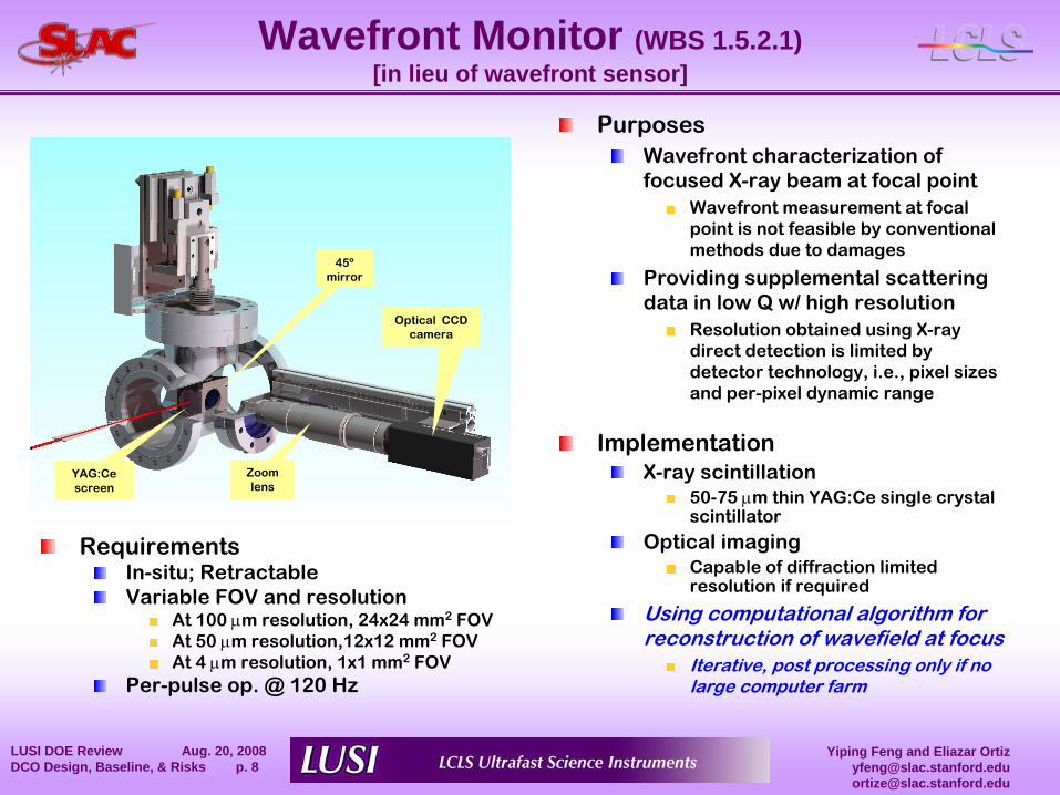
Wavefront Monitor (WBS 1.5.2.1) [in lieu of wavefront sensor]
YAG:Cescreen
45ºmirror
Optical CCD camera
Zoomlens
PurposesWavefront characterization of focused X-ray beam at focal point
Wavefront measurement at focal point is not feasible by conventional methods due to damages
Providing supplemental scattering data in low Q w/ high resolution
Resolution obtained using X-ray direct detection is limited by detector technology, i.e., pixel sizes and per-pixel dynamic range
ImplementationX-ray scintillation
50-75 μm thin YAG:Ce single crystal scintillator
Optical imagingCapable of
diffraction limited
resolution if required
Using computational algorithm for reconstruction of wavefield at focus
Iterative, post processing only if no large computer farm
RequirementsIn-situ; RetractableVariable FOV and resolution
At 100 μm resolution, 24x24 mm2
FOVAt 50 μm resolution,12x12 mm2
FOVAt 4 μm resolution, 1x1 mm2
FOVPer-pulse op. @ 120 Hz
Yiping Feng and Eliazar [email protected]@slac.stanford.edu
LUSI DOE Review Aug. 20, 2008 DCO Design, Baseline, & Risks p. 9
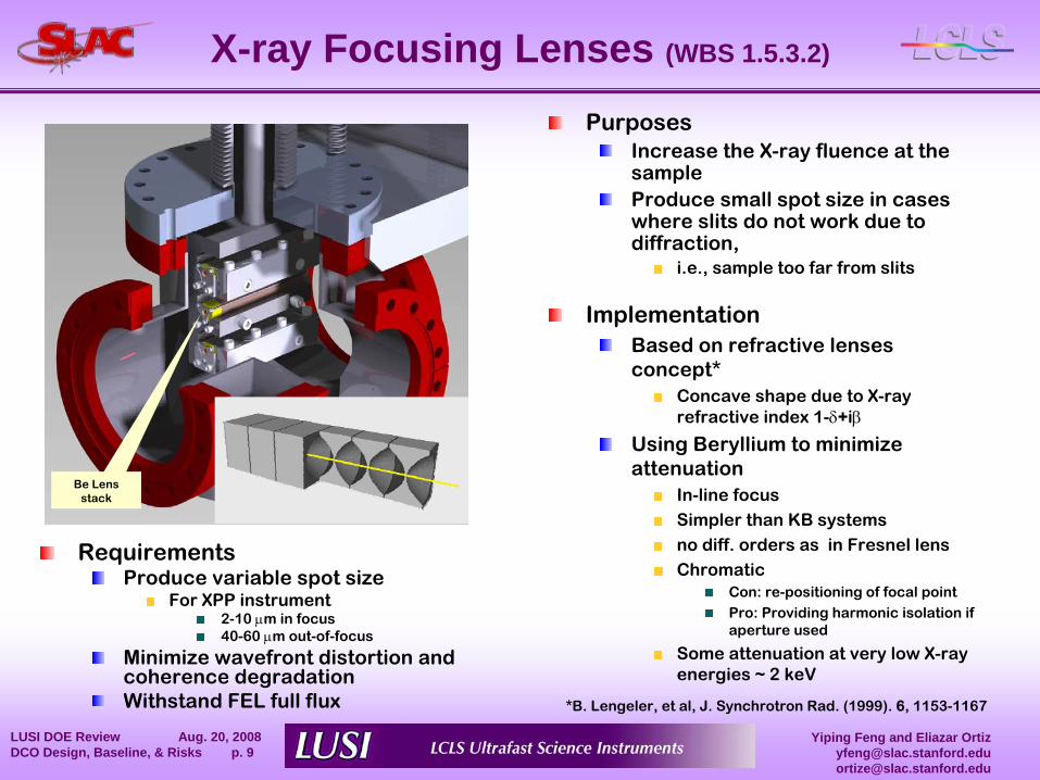
X-ray Focusing Lenses (WBS 1.5.3.2)
Be Lensstack
PurposesIncrease the X-ray fluence at the sampleProduce small spot size in cases where slits do not work due to diffraction,
i.e., sample too far from slits
ImplementationBased on refractive lenses concept*
Concave shape due to X-ray refractive index 1-δ+iβ
Using Beryllium to minimize attenuation
In-line focusSimpler than KB systemsno diff. orders as in Fresnel lensChromatic
Con: re-positioning of focal pointPro: Providing harmonic isolation if aperture used
Some attenuation at very low X-ray energies ~ 2 keV
RequirementsProduce variable spot size
For XPP instrument 2-10 μm in focus40-60 μm out-of-focus
Minimize wavefront distortion and coherence degradationWithstand FEL full flux *B. Lengeler, et al, J. Synchrotron Rad. (1999). 6, 1153-1167
Yiping Feng and Eliazar [email protected]@slac.stanford.edu
LUSI DOE Review Aug. 20, 2008 DCO Design, Baseline, & Risks p. 10
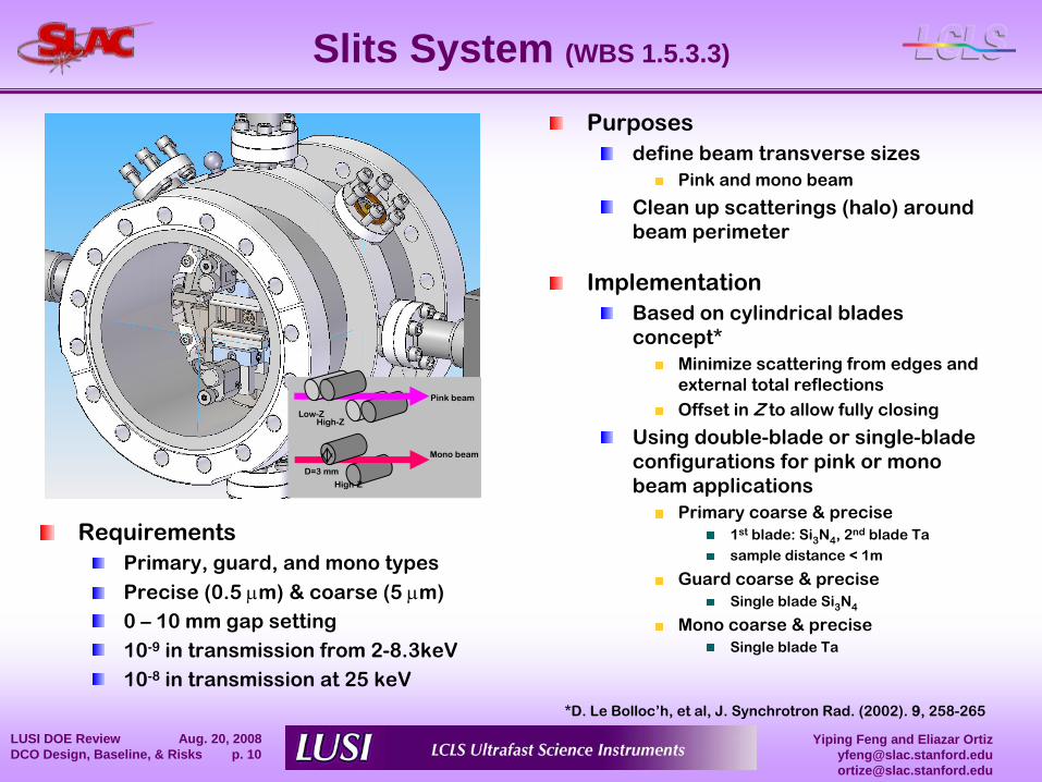
Slits System (WBS 1.5.3.3)
Purposesdefine beam transverse sizes
Pink and mono beam
Clean up scatterings (halo) around beam perimeter
ImplementationBased on cylindrical blades concept*
Minimize scattering from edges and external total reflectionsOffset in Z to allow fully closing
Using double-blade or single-blade configurations for pink or mono beam applications
Primary coarse & precise1st
blade: Si3
N4
, 2nd
blade Tasample distance < 1m
Guard coarse & preciseSingle blade Si3
N4
Mono coarse & preciseSingle blade Ta
High-ZLow-Z
High-Z
Pink beam
Mono beam
D=3 mm
RequirementsPrimary, guard, and mono types
Precise (0.5 μm) & coarse (5 μm)0 –
10 mm gap setting10-9
in transmission from 2-8.3keV10-8
in transmission at 25 keV
*D. Le Bolloc’h, et al, J. Synchrotron Rad. (2002). 9, 258-265
Yiping Feng and Eliazar [email protected]@slac.stanford.edu
LUSI DOE Review Aug. 20, 2008 DCO Design, Baseline, & Risks p. 11
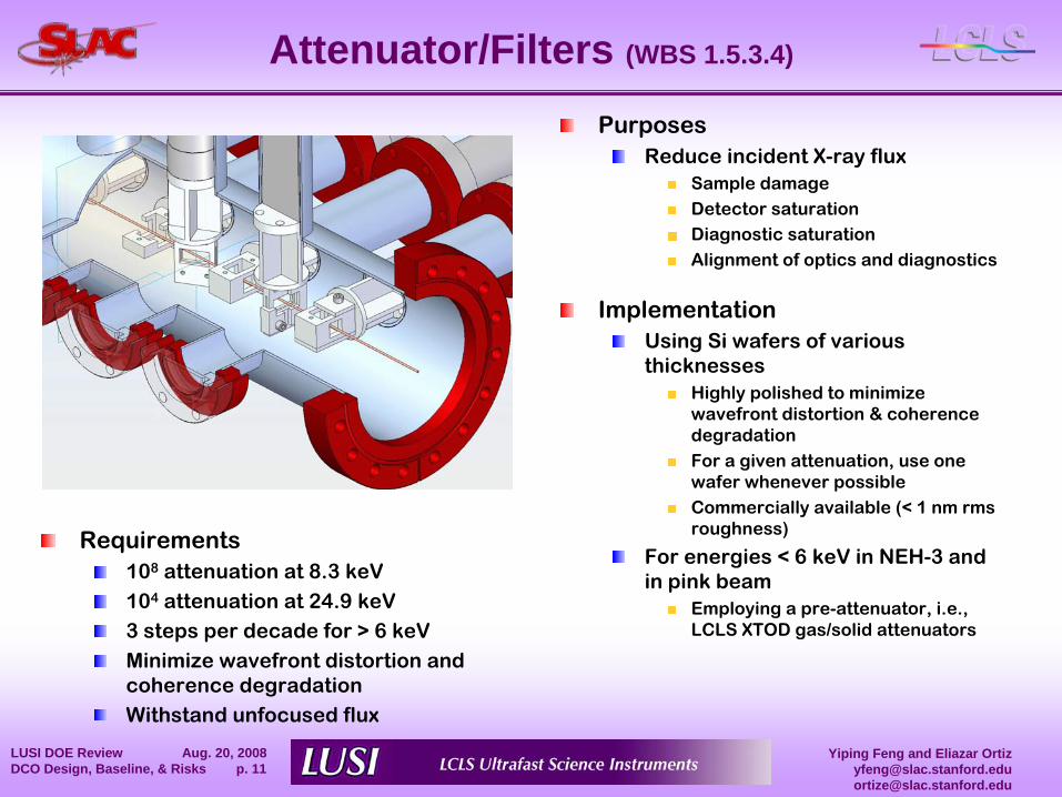
Attenuator/Filters (WBS 1.5.3.4)
PurposesReduce incident X-ray flux
Sample damageDetector saturationDiagnostic saturationAlignment of optics and diagnostics
ImplementationUsing Si wafers of various thicknesses
Highly polished to minimize wavefront distortion & coherence degradationFor a given attenuation, use one wafer whenever possible Commercially available (< 1 nm rms roughness)
For energies < 6 keV in NEH-3 and in pink beam
Employing a pre-attenuator, i.e., LCLS XTOD gas/solid attenuators
Requirements108
attenuation at 8.3 keV104
attenuation at 24.9 keV3 steps per decade for > 6 keVMinimize wavefront distortion and coherence degradationWithstand unfocused flux
Yiping Feng and Eliazar [email protected]@slac.stanford.edu
LUSI DOE Review Aug. 20, 2008 DCO Design, Baseline, & Risks p. 12
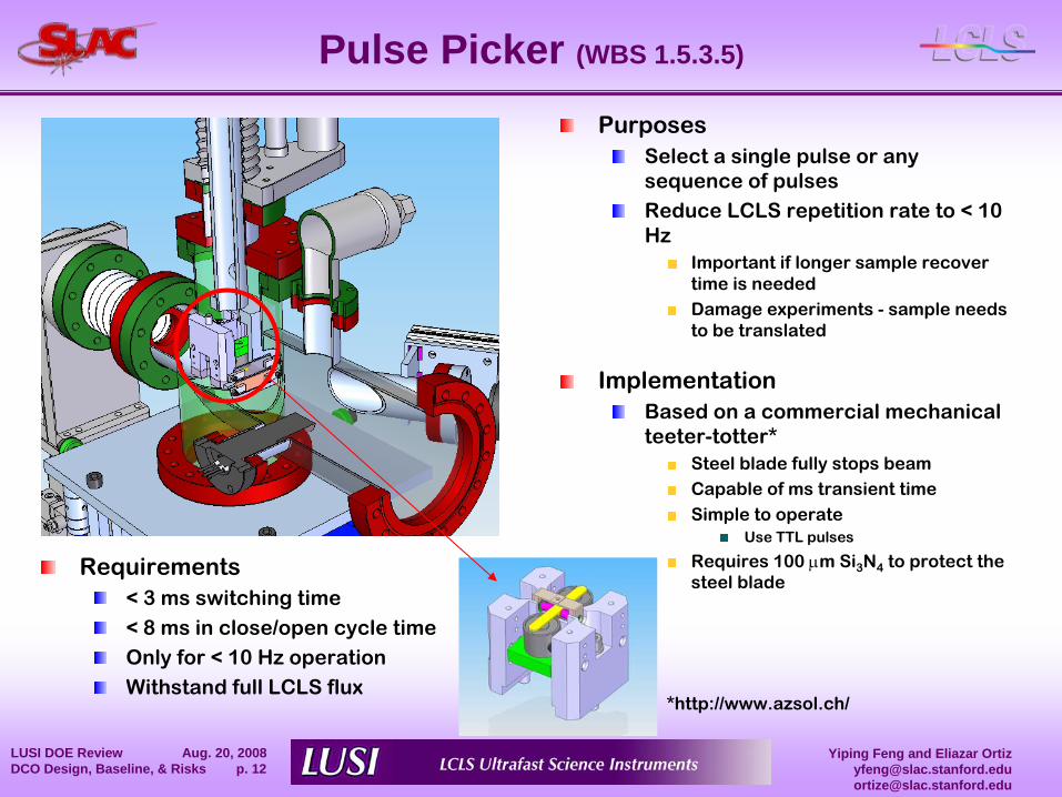
Pulse Picker (WBS 1.5.3.5)
*http://www.azsol.ch/
PurposesSelect a single pulse or any sequence of pulsesReduce LCLS repetition rate to < 10 Hz
Important if longer sample recover time is neededDamage experiments -
sample needs to be translated
ImplementationBased on a commercial mechanical teeter-totter*
Steel blade fully stops beamCapable of ms transient time Simple to operate
Use TTL pulses
Requires 100 μm Si3
N4
to protect the steel blade
Requirements< 3 ms switching time< 8 ms in close/open cycle timeOnly for < 10 Hz operationWithstand full LCLS flux
Yiping Feng and Eliazar [email protected]@slac.stanford.edu
LUSI DOE Review Aug. 20, 2008 DCO Design, Baseline, & Risks p. 13
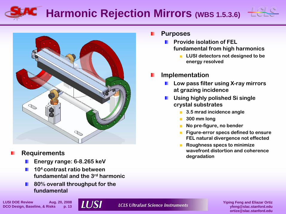
Harmonic Rejection Mirrors (WBS 1.5.3.6)
PurposesProvide isolation of FEL fundamental from high harmonics
LUSI detectors not designed to be energy resolved
ImplementationLow pass filter using X-ray mirrors at grazing incidenceUsing highly polished Si single crystal substrates
3.5 mrad incidence angle300 mm long No pre-figure, no benderFigure-error specs defined to ensure FEL natural divergence not effectedRoughness specs to minimize wavefront distortion and coherence degradation
RequirementsEnergy range: 6-8.265 keV104 contrast ratio between fundamental and the 3rd
harmonic80% overall throughput for the fundamental
Yiping Feng and Eliazar [email protected]@slac.stanford.edu
LUSI DOE Review Aug. 20, 2008 DCO Design, Baseline, & Risks p. 14
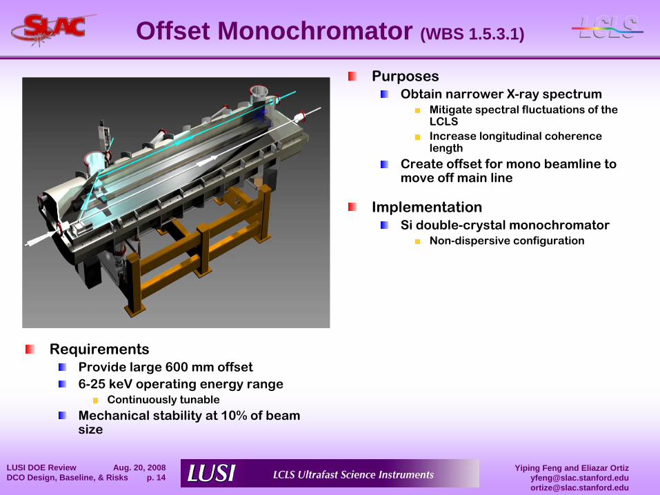
Offset Monochromator (WBS 1.5.3.1)
PurposesObtain narrower X-ray spectrum
Mitigate spectral fluctuations of the LCLSIncrease longitudinal coherence length
Create offset for mono beamline to move off main line
ImplementationSi double-crystal monochromator
Non-dispersive configuration
RequirementsProvide large 600 mm offset6-25 keV operating energy range
Continuously tunable
Mechanical stability at 10% of beam size

Yiping Feng and Eliazar [email protected]@slac.stanford.edu
LUSI DOE Review Aug. 20, 2008 DCO Design, Baseline, & Risks p. 15
SafetySafety issues are considered at every stage of the design, fabrication and installation process per SLAC Integrated Safety and Environmental Management
SystemDefine WorkAnalyze Hazards:
Identify hazards associated with the design and operation of the
LUSI project Each design review addresses appropriate safety considerations for the level of completion of the design and the particular item covered
Develop ControlsControls are planned to mitigate or eliminate hazard capable of causing injury to personnel, harm to the environment, or damage to critical hardware
Perform WorkObtain feedback and improve
The Hazards Analysis Report (HAR), PM-391-001-34 R0, documents the safety analysis of the LUSI instrument design/build/install & testSafety considerations (some examples)
Pressure/Vacuum Vessel SafetyCompliant with 10CFR851
Seismic SafetyDesigns compliant with: Seismic Design Specification for Buildings, Structures, Equipment, and Systems, SLAC-I-720-0A24E-002-R002
MechanicalEngineered solutions that prevent potential “pinch-points”
with moving machinery
Hoisting and RiggingHoisting and rigging is performed by qualified personnel only with an approved lift plan.
Yiping Feng and Eliazar [email protected]@slac.stanford.edu
LUSI DOE Review Aug. 20, 2008 DCO Design, Baseline, & Risks p. 16
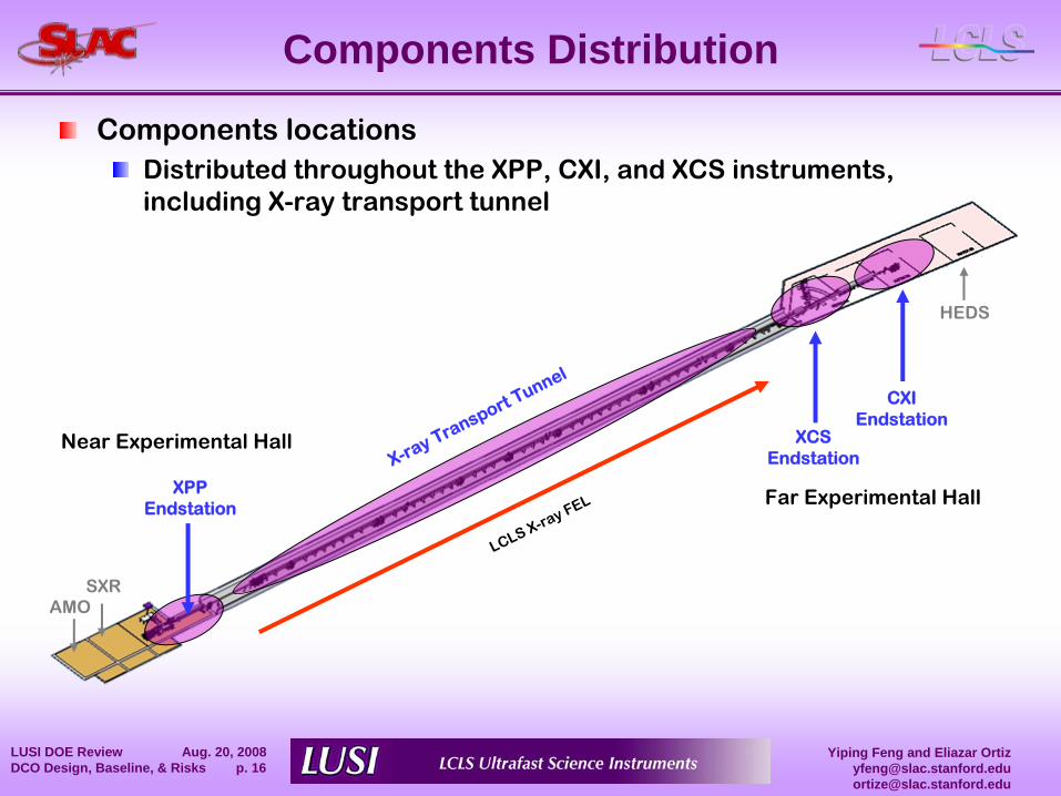
Components Distribution
Components locationsDistributed throughout the XPP, CXI, and XCS instruments, including X-ray transport tunnel
SXR
CXIEndstation
Near Experimental Hall
Far Experimental Hall
X-ray Transport Tunnel
XCSEndstation
XPPEndstation
AMO
HEDS
LCLS X-ray FEL
Yiping Feng and Eliazar [email protected]@slac.stanford.edu
LUSI DOE Review Aug. 20, 2008 DCO Design, Baseline, & Risks p. 17
Components Distribution (cont.)
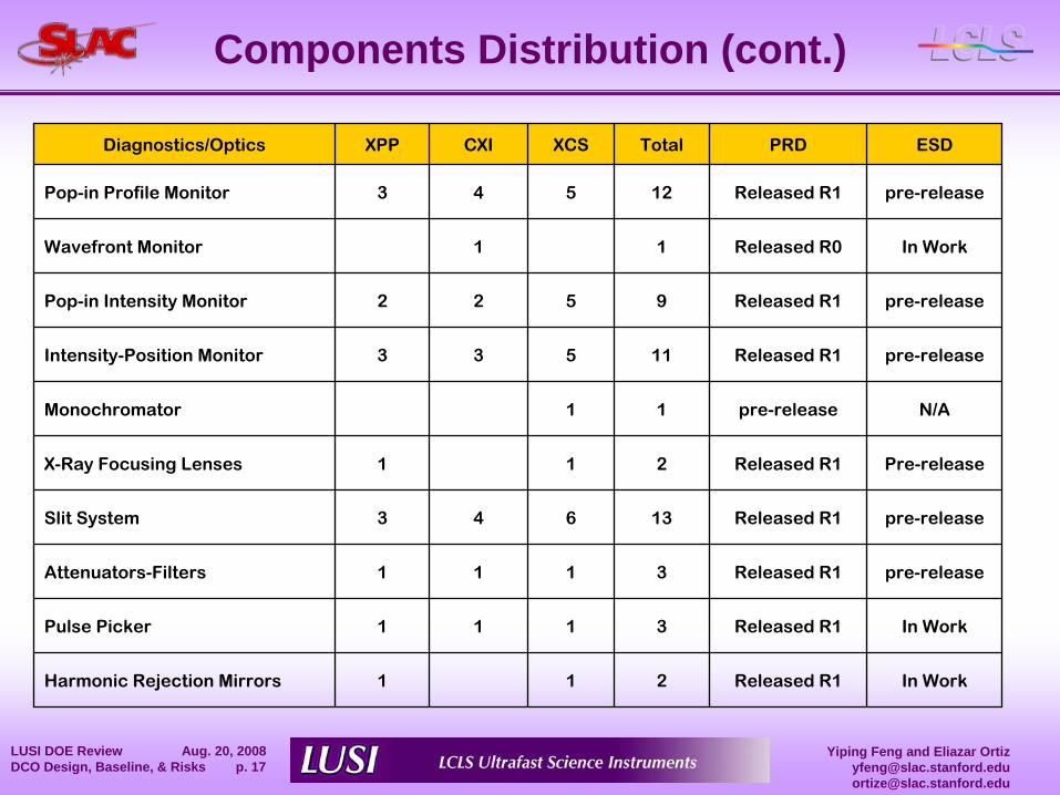
Diagnostics/Optics XPP CXI XCS Total PRD ESD
Pop-in Profile Monitor 3 4 5 12 Released R1 pre-release
Wavefront Monitor 1 1 Released R0 In Work
Pop-in Intensity Monitor 2 2 5 9 Released R1 pre-release
Intensity-Position Monitor 3 3 5 11 Released R1 pre-release
Monochromator 1 1 pre-release N/A
X-Ray Focusing Lenses 1 1 2 Released R1 Pre-release
Slit System 3 4 6 13 Released R1 pre-release
Attenuators-Filters 1 1 1 3 Released R1 pre-release
Pulse Picker 1 1 1 3 Released R1 In Work
Harmonic Rejection Mirrors 1 1 2 Released R1 In Work
Yiping Feng and Eliazar [email protected]@slac.stanford.edu
LUSI DOE Review Aug. 20, 2008 DCO Design, Baseline, & Risks p. 18
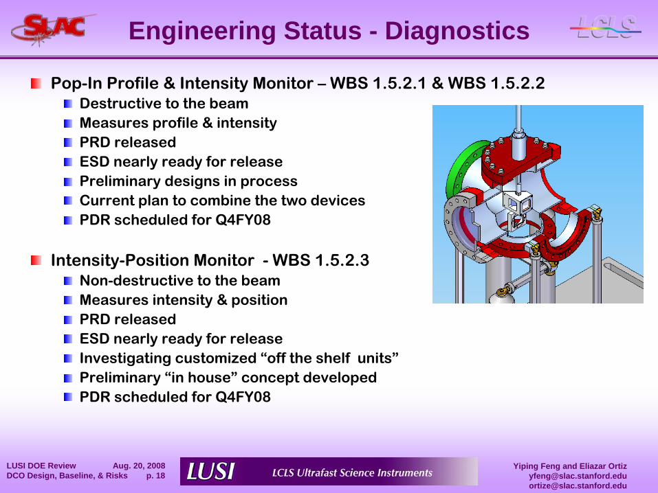
Engineering Status - Diagnostics
Pop-In Profile & Intensity Monitor –
WBS 1.5.2.1 & WBS 1.5.2.2Destructive to the beamMeasures profile & intensityPRD releasedESD nearly ready for releasePreliminary designs in processCurrent plan to combine the two devicesPDR scheduled for Q4FY08
Intensity-Position Monitor -
WBS 1.5.2.3Non-destructive to the beamMeasures intensity & positionPRD releasedESD nearly ready for releaseInvestigating customized “off the shelf units”Preliminary “in house”
concept developedPDR scheduled for Q4FY08
Yiping Feng and Eliazar [email protected]@slac.stanford.edu
LUSI DOE Review Aug. 20, 2008 DCO Design, Baseline, & Risks p. 19
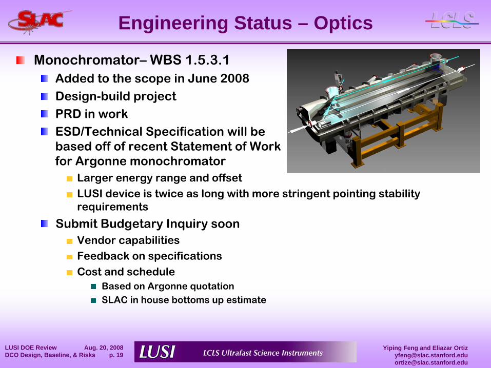
Engineering Status – Optics
Monochromator–
WBS 1.5.3.1Added to the scope in June 2008
Design-build projectPRD in workESD/Technical Specification will be based off of recent Statement of Work for Argonne monochromator
Larger energy range and offsetLUSI device is twice as long with more stringent pointing stability requirements
Submit Budgetary Inquiry soonVendor capabilitiesFeedback on specificationsCost and schedule
Based on Argonne quotationSLAC in house bottoms up estimate
Yiping Feng and Eliazar [email protected]@slac.stanford.edu
LUSI DOE Review Aug. 20, 2008 DCO Design, Baseline, & Risks p. 20
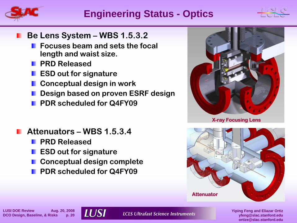
Engineering Status - Optics
Be Lens System –
WBS 1.5.3.2Focuses beam and sets the focal length and waist size.PRD ReleasedESD out for signatureConceptual design in workDesign based on proven ESRF designPDR scheduled for Q4FY09
Attenuators –
WBS 1.5.3.4PRD ReleasedESD out for signatureConceptual design completePDR scheduled for Q4FY09
Attenuator
X-ray Focusing Lens
Yiping Feng and Eliazar [email protected]@slac.stanford.edu
LUSI DOE Review Aug. 20, 2008 DCO Design, Baseline, & Risks p. 21
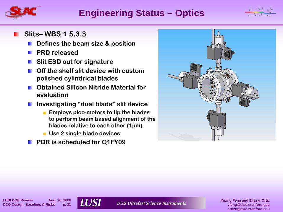
Engineering Status – Optics
Slits–
WBS 1.5.3.3Defines the beam size & positionPRD releasedSlit ESD out for signatureOff the shelf slit device with custom polished cylindrical bladesObtained Silicon Nitride Material for evaluationInvestigating “dual blade”
slit deviceEmploys pico-motors to tip the blades to perform beam based alignment of the blades relative to each other (1μm).Use 2 single blade devices
PDR is scheduled for Q1FY09
Yiping Feng and Eliazar [email protected]@slac.stanford.edu
LUSI DOE Review Aug. 20, 2008 DCO Design, Baseline, & Risks p. 22
Engineering Status - Optics
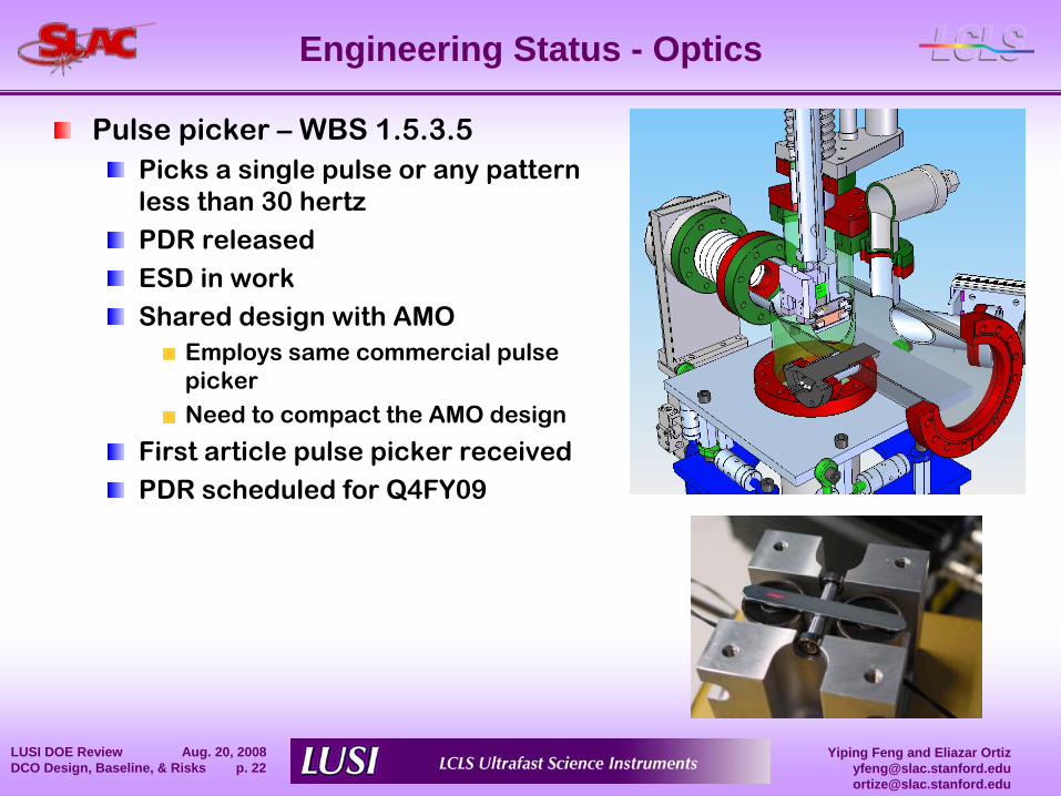
Pulse picker –
WBS 1.5.3.5Picks a single pulse or any pattern less than 30 hertzPDR releasedESD in work
Shared design with AMOEmploys same commercial pulse pickerNeed to compact the AMO design
First article pulse picker receivedPDR scheduled for Q4FY09
Yiping Feng and Eliazar [email protected]@slac.stanford.edu
LUSI DOE Review Aug. 20, 2008 DCO Design, Baseline, & Risks p. 23
Engineering Status – Optics
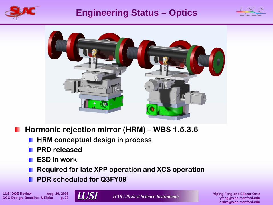
Harmonic rejection mirror (HRM) –
WBS 1.5.3.6HRM conceptual design in process
PRD releasedESD in workRequired for late XPP operation and XCS operation
PDR scheduled for Q3FY09
Yiping Feng and Eliazar [email protected]@slac.stanford.edu
LUSI DOE Review Aug. 20, 2008 DCO Design, Baseline, & Risks p. 24
Engineering Status
Major Upcoming MilestonesQ4 FY2008 –
PDR Pop-In Profile Monitor
Q4 FY2008 –
PDR Pop-In Intensity MonitorQ4 FY2008 –
PDR Pulse PickerQ1 FY2009 –
PDR Intensity-Position Monitor
Q1 FY2009 –
PDR Slit SystemQ1 FY2009 –
FDR Slits systemQ1 FY2009 –
FDR Pulse picker
Yiping Feng and Eliazar [email protected]@slac.stanford.edu
LUSI DOE Review Aug. 20, 2008 DCO Design, Baseline, & Risks p. 25
Value Engineering / Management
Component Value Management /Design Alternatives Considered
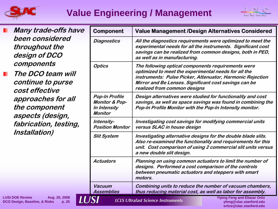
Diagnostics All the diagnostics requirements were optimized to meet the experimental needs for all the instruments. Significant cost savings can be realized from common designs, both in PED, as well as in manufacturing.
Optics The following optical components requirements were optimized to meet the experimental needs for all the instruments: Pulse Picker, Attenuator, Harmonic Rejection Mirror and Be Lenses. Significant cost savings can be realized from common designs
Pop-In Profile Monitor & Pop-
In Intensity Monitor
Design alternatives were studied for functionality and cost savings, as well as space savings was found in combining the Pop-In Profile Monitor with the Pop-In Intensity monitor.
Intensity-
Position MonitorInvestigating cost savings for modifying commercial units versus SLAC in house design
Slit System Investigating alternative designs for the double blade slits. Also re-examined the functionality and requirements for this unit. Cost comparison of using 2 commercial slit units versus a new double slit design.
Actuators Planning on using common actuators to limit the number of designs. Performed a cost comparison of the controls between pneumatic actuators and steppers with smart motors.
Vacuum Assemblies
Combining units to reduce the number of vacuum chambers, thus reducing material cost, as well as labor for assembly.
Many trade-offs have been considered throughout the design of DCO componentsThe DCO team will continue to purse cost effective approaches for all the component aspects (design, fabrication, testing, Installation)
Yiping Feng and Eliazar [email protected]@slac.stanford.edu
LUSI DOE Review Aug. 20, 2008 DCO Design, Baseline, & Risks p. 26
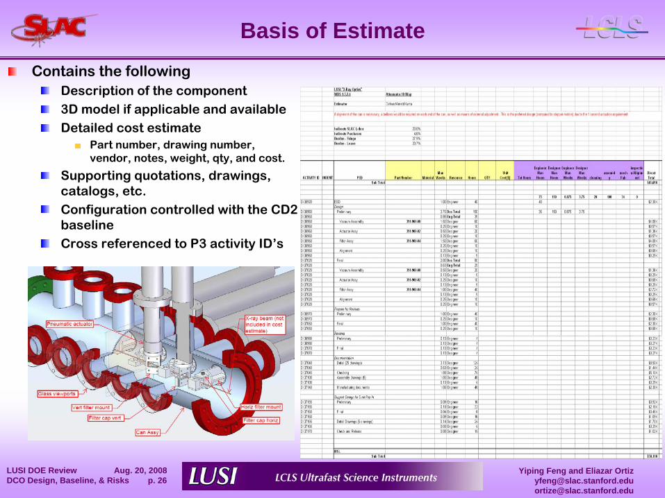
Basis of EstimateContains the following
Description of the component3D model if applicable and availableDetailed cost estimate
Part number, drawing number, vendor, notes, weight, qty, and cost.
Supporting quotations, drawings, catalogs, etc.Configuration controlled with the CD2 baselineCross referenced to P3 activity ID’s
Yiping Feng and Eliazar [email protected]@slac.stanford.edu
LUSI DOE Review Aug. 20, 2008 DCO Design, Baseline, & Risks p. 27
Procurement Strategy
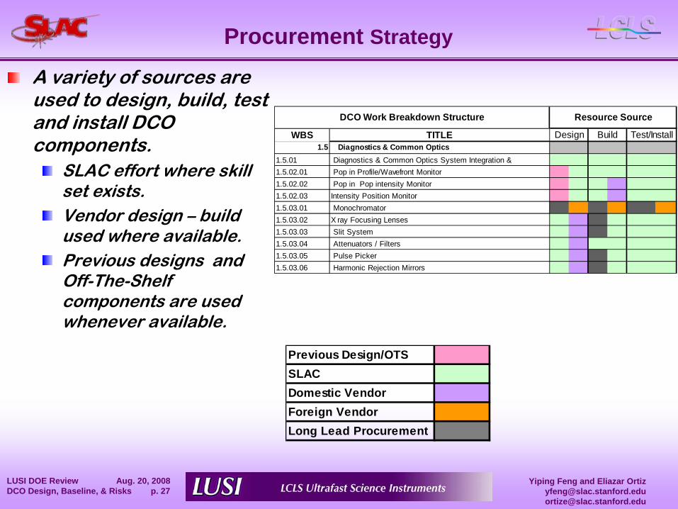
WBS TITLE1.5 Diagnostics & Common Optics
1.5.01 Diagnostics & Common Optics System Integration &1.5.02.01 Pop in Profile/Wavefront Monitor1.5.02.02 Pop in Pop intensity Monitor1.5.02.03 Intensity Position Monitor1.5.03.01 Monochromator1.5.03.02 X ray Focusing Lenses1.5.03.03 Slit System1.5.03.04 Attenuators / Filters1.5.03.05 Pulse Picker1.5.03.06 Harmonic Rejection Mirrors
DCO Work Breakdown Structure Resource Source
Design Test/InstallBuild
Previous Design/OTSSLACDomestic VendorForeign VendorLong Lead Procurement
A variety of sources are used to design, build, test and install DCO components.
SLAC effort where skill set exists.Vendor design – build used where available.Previous designs and Off-The-Shelf components are used whenever available.
Yiping Feng and Eliazar [email protected]@slac.stanford.edu
LUSI DOE Review Aug. 20, 2008 DCO Design, Baseline, & Risks p. 28
DCO Cost & Schedule
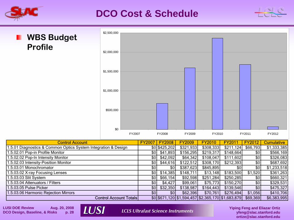
WBS Budget Profile
$0
$500,000
$1,000,000
$1,500,000
$2,000,000
$2,500,000
FY2007 FY2008 FY2009 FY2010 FY2011 FY2012
Control Account FY2007 FY2008 FY2009 FY2010 FY2011 FY2012 Cumulative1.5.01 Diagnostics & Common Optics System Integration & Design $0 $425,202 $321,933 $308,333 $211,124 $66,793 $1,333,3851.5.02.01 Pop-in Profile Monitor $0 $41,893 $156,295 $219,317 $148,664 $0 $566,1691.5.02.02 Pop-In Intensity Monitor $0 $42,092 $64,342 $108,047 $111,602 $0 $326,0831.5.02.03 Intensity-Position Monitor $0 $44,616 $122,512 $308,170 $212,393 $0 $687,6921.5.03.01 Monochromator $0 $0 $387,623 $845,895 $0 $0 $1,233,5181.5.03.02 X-ray Focusing Lenses $0 $14,385 $148,711 $13,148 $183,500 $1,520 $361,2631.5.03.03 Slit System $0 $66,154 $92,598 $251,284 $250,285 $0 $660,3211.5.03.04 Attenuators / Filters $0 $4,427 $99,061 $75,773 $150,270 $0 $329,5311.5.03.05 Pulse Picker $0 $32,350 $138,987 $164,443 $139,546 $0 $475,3271.5.03.06 Harmonic Rejection Mirrors $0 $0 $62,396 $70,761 $276,494 $1,056 $410,706
Control Account Totals $0 $671,120 $1,594,457 $2,365,170 $1,683,879 $69,369 $6,383,995
Yiping Feng and Eliazar [email protected]@slac.stanford.edu
LUSI DOE Review Aug. 20, 2008 DCO Design, Baseline, & Risks p. 29
DCO Cost & Schedule
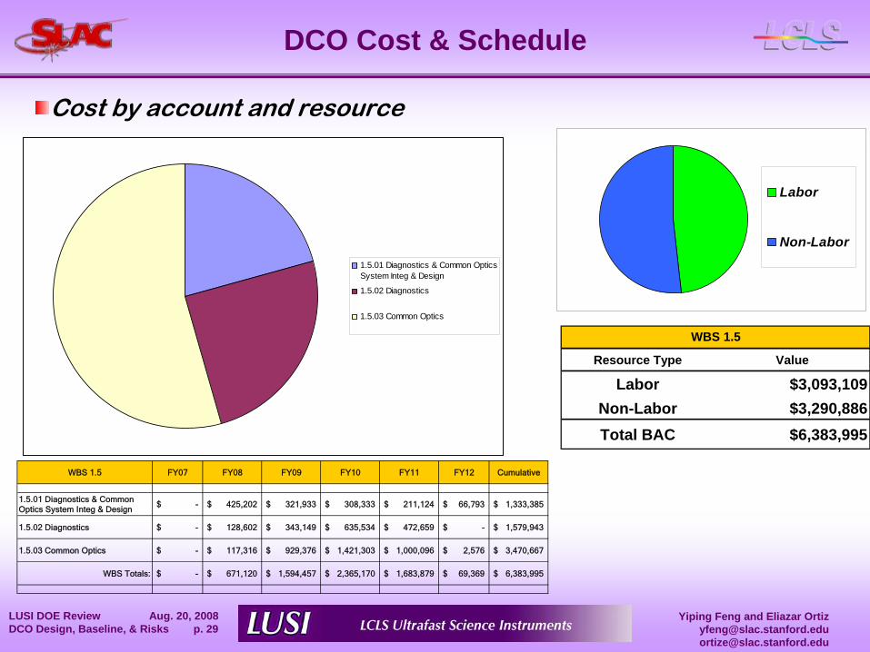
Resource Type Value
Labor $3,093,109Non-Labor $3,290,886Total BAC $6,383,995
WBS 1.5
Labor
Non-Labor
WBS 1.5 FY07 FY08 FY09 FY10 FY11 FY12 Cumulative
1.5.01 Diagnostics & Common Optics System Integ & Design
-$ 425,202$ 321,933$ 308,333$ 211,124$ 66,793$ 1,333,385$
1.5.02 Diagnostics -$ 128,602$ 343,149$ 635,534$ 472,659$ -$ 1,579,943$
1.5.03 Common Optics -$ 117,316$ 929,376$ 1,421,303$ 1,000,096$ 2,576$ 3,470,667$
WBS Totals: -$ 671,120$ 1,594,457$ 2,365,170$ 1,683,879$ 69,369$ 6,383,995$
1.5.01 Diagnostics & Common OpticsSystem Integ & Design
1.5.02 Diagnostics
1.5.03 Common Optics
Cost by account and resource
Yiping Feng and Eliazar [email protected]@slac.stanford.edu
LUSI DOE Review Aug. 20, 2008 DCO Design, Baseline, & Risks p. 30
DCO Cost & Schedule
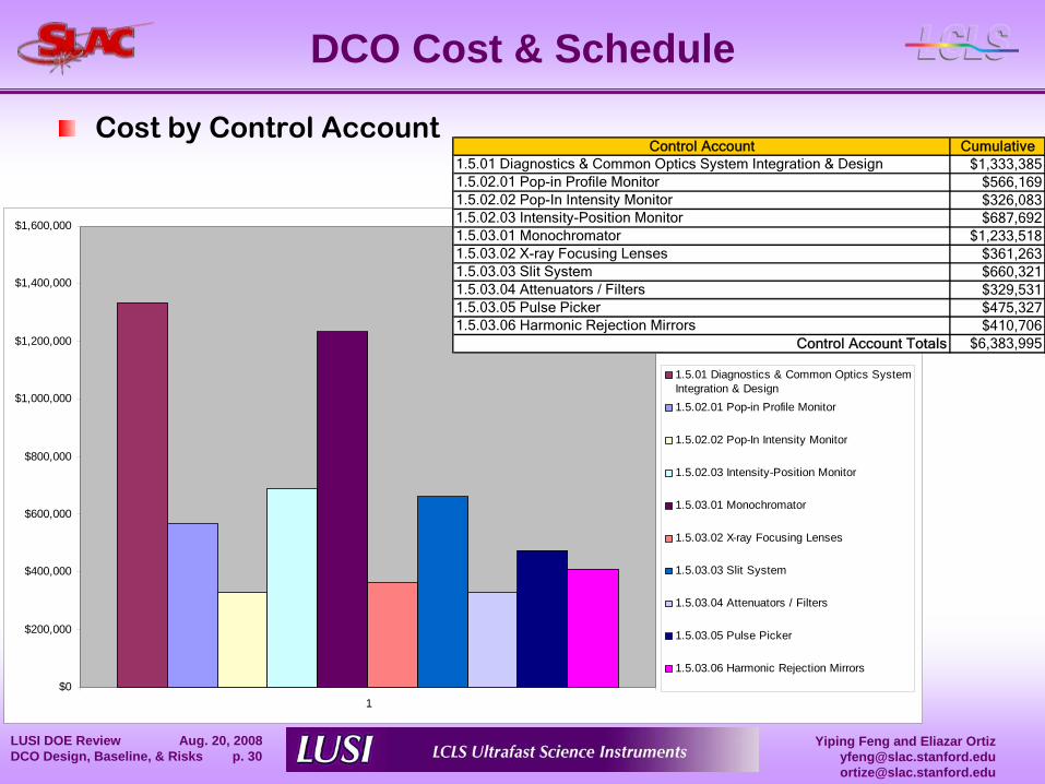
Cost by Control Account
$0
$200,000
$400,000
$600,000
$800,000
$1,000,000
$1,200,000
$1,400,000
$1,600,000
1
1.5.01 Diagnostics & Common Optics SystemIntegration & Design1.5.02.01 Pop-in Profile Monitor
1.5.02.02 Pop-In Intensity Monitor
1.5.02.03 Intensity-Position Monitor
1.5.03.01 Monochromator
1.5.03.02 X-ray Focusing Lenses
1.5.03.03 Slit System
1.5.03.04 Attenuators / Filters
1.5.03.05 Pulse Picker
1.5.03.06 Harmonic Rejection Mirrors
Control Account Cumulative1.5.01 Diagnostics & Common Optics System Integration & Design $1,333,3851.5.02.01 Pop-in Profile Monitor $566,1691.5.02.02 Pop-In Intensity Monitor $326,0831.5.02.03 Intensity-Position Monitor $687,6921.5.03.01 Monochromator $1,233,5181.5.03.02 X-ray Focusing Lenses $361,2631.5.03.03 Slit System $660,3211.5.03.04 Attenuators / Filters $329,5311.5.03.05 Pulse Picker $475,3271.5.03.06 Harmonic Rejection Mirrors $410,706
Control Account Totals $6,383,995
Yiping Feng and Eliazar [email protected]@slac.stanford.edu
LUSI DOE Review Aug. 20, 2008 DCO Design, Baseline, & Risks p. 31
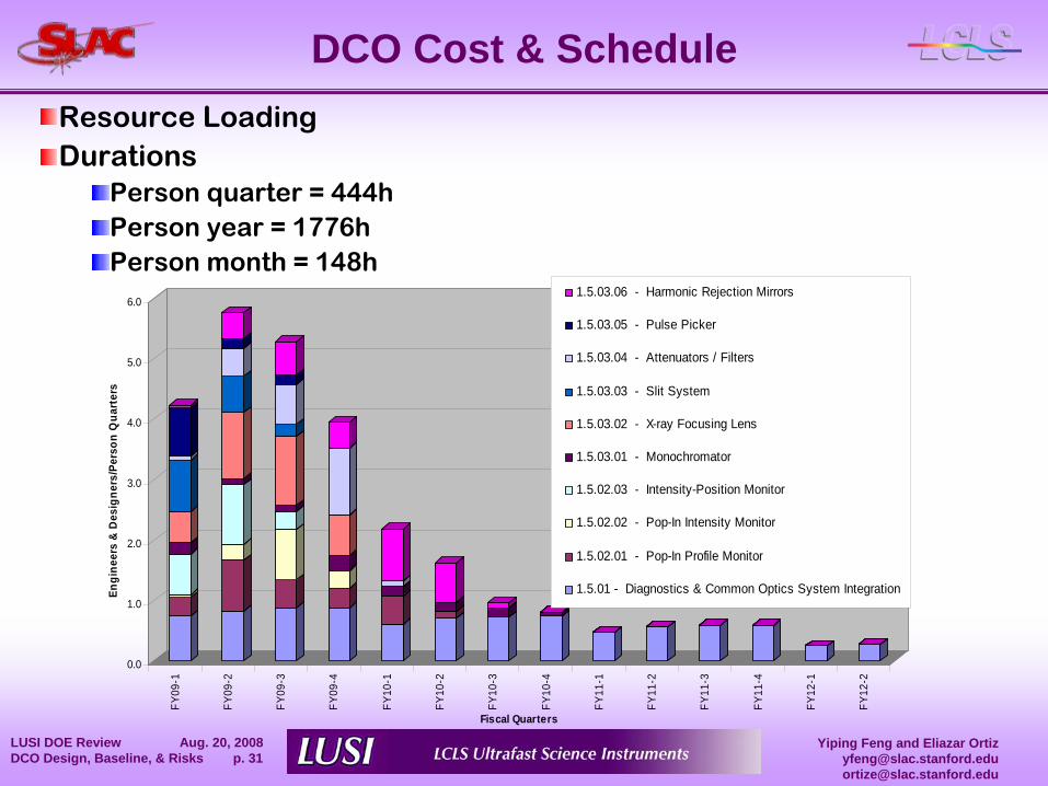
DCO Cost & ScheduleResource LoadingDurations
Person quarter = 444hPerson year = 1776hPerson month = 148h
0.0
1.0
2.0
3.0
4.0
5.0
6.0
Engi
neer
s &
Des
igne
rs/P
erso
n Q
uart
ers
FY09
-1
FY09
-2
FY09
-3
FY09
-4
FY10
-1
FY10
-2
FY10
-3
FY10
-4
FY11
-1
FY11
-2
FY11
-3
FY11
-4
FY12
-1
FY12
-2
Fiscal Quarters
1.5.03.06 - Harmonic Rejection Mirrors
1.5.03.05 - Pulse Picker
1.5.03.04 - Attenuators / Filters
1.5.03.03 - Slit System
1.5.03.02 - X-ray Focusing Lens
1.5.03.01 - Monochromator
1.5.02.03 - Intensity-Position Monitor
1.5.02.02 - Pop-In Intensity Monitor
1.5.02.01 - Pop-In Profile Monitor
1.5.01 - Diagnostics & Common Optics System Integration
Yiping Feng and Eliazar [email protected]@slac.stanford.edu
LUSI DOE Review Aug. 20, 2008 DCO Design, Baseline, & Risks p. 32
DCO Cost & Schedule
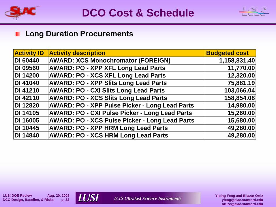
Long Duration Procurements
Activity ID Activity description Budgeted costDI 60440 AWARD: XCS Monochromator (FOREIGN) 1,158,831.40DI 09560 AWARD: PO - XPP XFL Long Lead Parts 11,770.00DI 14200 AWARD: PO - XCS XFL Long Lead Parts 12,320.00DI 41040 AWARD: PO - XPP Slits Long Lead Parts 75,881.19DI 41210 AWARD: PO - CXI Slits Long Lead Parts 103,066.04DI 42110 AWARD: PO - XCS Slits Long Lead Parts 158,854.08DI 12820 AWARD: PO - XPP Pulse Picker - Long Lead Parts 14,980.00DI 14105 AWARD: PO - CXI Pulse Picker - Long Lead Parts 15,260.00DI 16005 AWARD: PO - XCS Pulse Picker - Long Lead Parts 15,680.00DI 10445 AWARD: PO - XPP HRM Long Lead Parts 49,280.00DI 14840 AWARD: PO - XCS HRM Long Lead Parts 49,280.00
Yiping Feng and Eliazar [email protected]@slac.stanford.edu
LUSI DOE Review Aug. 20, 2008 DCO Design, Baseline, & Risks p. 33
DCO Cost & Schedule
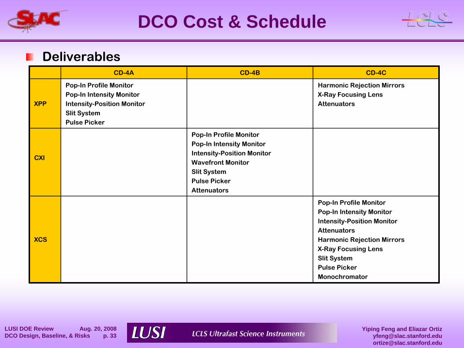
DeliverablesCD-4A CD-4B CD-4C
XPP
Pop-In Profile MonitorPop-In Intensity MonitorIntensity-Position MonitorSlit SystemPulse Picker
Harmonic Rejection MirrorsX-Ray Focusing LensAttenuators
CXI
Pop-In Profile MonitorPop-In Intensity MonitorIntensity-Position MonitorWavefront MonitorSlit SystemPulse PickerAttenuators
XCS
Pop-In Profile MonitorPop-In Intensity MonitorIntensity-Position Monitor AttenuatorsHarmonic Rejection MirrorsX-Ray Focusing LensSlit SystemPulse PickerMonochromator
Yiping Feng and Eliazar [email protected]@slac.stanford.edu
LUSI DOE Review Aug. 20, 2008 DCO Design, Baseline, & Risks p. 34
Critical Path1st
Critical PathDriven by funding milestones on long duration part procurement
AWARD: PO -
XCS XFL Long Lead Parts
2nd
Critical PathPDR -
Prelim Design Review -
Intensity Position MonAWARD: PO -
XPP IO Mon 1st Article PartsAWARD: PO -
XCS HRM Long Lead Parts
Additional float could be generated by allocating procurement funds to DCO earlier TOTAL SCHEDULE FLOAT for DCO is 80 days.
Yiping Feng and Eliazar [email protected]@slac.stanford.edu
LUSI DOE Review Aug. 20, 2008 DCO Design, Baseline, & Risks p. 35
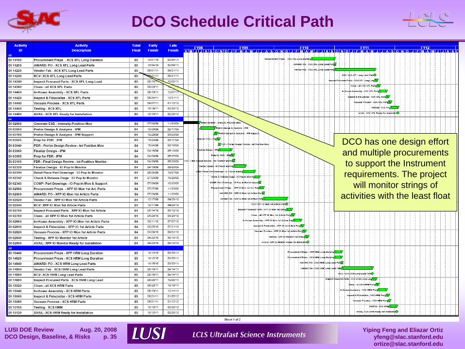
DCO Schedule Critical Path
DCO has one design effort and multiple procurements to support the Instrument requirements. The project
will monitor strings of activities with the least float
Yiping Feng and Eliazar [email protected]@slac.stanford.edu
LUSI DOE Review Aug. 20, 2008 DCO Design, Baseline, & Risks p. 36
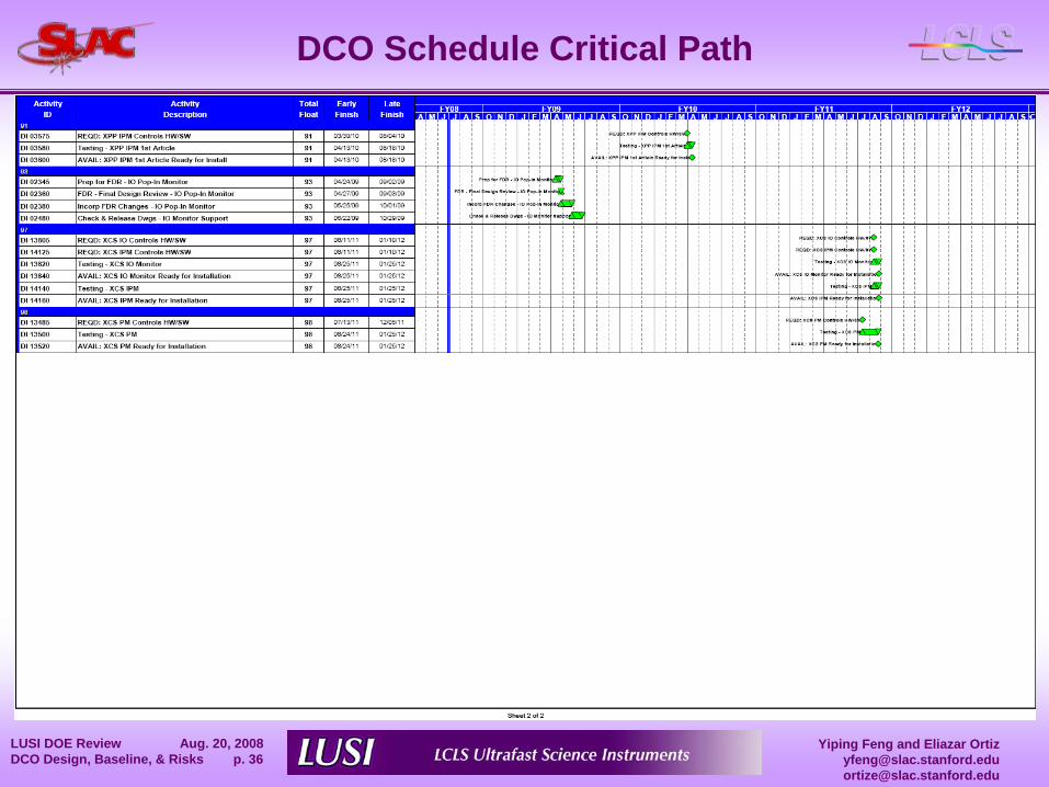
DCO Schedule Critical Path
Yiping Feng and Eliazar [email protected]@slac.stanford.edu
LUSI DOE Review Aug. 20, 2008 DCO Design, Baseline, & Risks p. 37
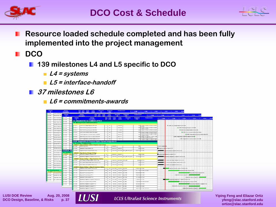
DCO Cost & Schedule
Resource loaded schedule completed and has been fully implemented into the project managementDCO
139 milestones L4 and L5 specific to DCOL4 = systemsL5 = interface-handoff
37 milestones L6L6 = commitments-awards
Yiping Feng and Eliazar [email protected]@slac.stanford.edu
LUSI DOE Review Aug. 20, 2008 DCO Design, Baseline, & Risks p. 38
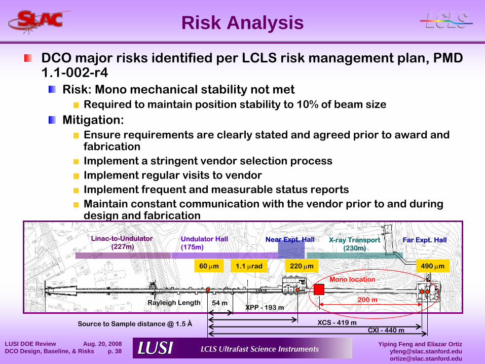
Risk Analysis
DCO major risks identified per LCLS risk management plan, PMD 1.1-002-r4
Risk: Mono mechanical stability not metRequired to maintain position stability to 10% of beam size
Mitigation:Ensure requirements are clearly stated and agreed prior to award
and fabrication Implement a stringent vendor selection process Implement regular visits to vendor Implement frequent and measurable status reports Maintain constant communication with the vendor prior to and during design and fabrication
Linac-to-Undulator(227m)
Undulator Hall (175m)
Near Expt. Hall X-ray Transport(230m)
Far Expt. Hall
Source to Sample distance @ 1.5 ÅCXI -
440 mXCS -
419 m
XPP -
193 m54 mRayleigh Length
60 μm 220 μm 490 μm1.1 μrad
Mono location
200 m
Yiping Feng and Eliazar [email protected]@slac.stanford.edu
LUSI DOE Review Aug. 20, 2008 DCO Design, Baseline, & Risks p. 39
Summary
Scope of DCO components for XPP, CXI, and XCS instruments fully definedThe design of key diagnostics devices and optical components is mature and based on proven developments
at FLASH, SPPS, synchrotron sources worldwideby LCLS-XTOD group
DCO components have a consistent cost estimate.Resource loaded schedule developed through end of project Critical Path is defined Advanced Procurements identifiedDCO is ready for CD2 approval!