Embed Size (px)
Citation preview
Research ArticleDevelopment and Performance Analysis of Pneumatic Soft-BodiedBionic Actuator
Wenchuan Zhao , Yu Zhang , and Ning Wang
School of Mechanical Engineering, Shenyang University of Technology, Shenyang 110870, China
Correspondence should be addressed to Yu Zhang; [email protected]
Received 10 December 2020; Revised 22 January 2021; Accepted 9 February 2021; Published 19 February 2021
Academic Editor: Donato Romano
Copyright © 2021 Wenchuan Zhao et al. This is an open access article distributed under the Creative Commons AttributionLicense, which permits unrestricted use, distribution, and reproduction in any medium, provided the original work isproperly cited.
The design of a pneumatic soft-bodied bionic actuator derives from the structural characteristics and motion mechanism ofbiological muscles, combined with the nonlinear hyperelasticity of silica gel, which can improve the mobility and environmentaladaptability of soft-bodied bionic robots. Based on Yeoh’s second-order constitutive model of silica gel, the deformation analysismodel of the actuator is established, and the rationality of the structure design and motion forms of the actuator and theaccuracy of the deformation analysis model are verified by using the numerical simulation algorithm. According to the physicalmodel of the pneumatic soft-bodied bionic actuator, the motion and dynamic characteristics of the actuator are tested andanalyzed, the curves of motion and dynamic characteristics of the actuator are obtained, and the empirical formula of thebending angle and driving torque of the actuator is fitted out. The results show that the deformation analysis model andnumerical simulation method are accurate, and the pneumatic soft-bodied bionic actuator is feasible and effective, which canprovide a design method and reference basis for the research and implementation of soft-bodied bionic robot actuator.
1. Introduction
The traditional robot is composed of a large number of rigidparts, which face the disadvantages of low human-computerinteraction security, poor adaptability in unstructured envi-ronment, low driving efficiency, and high maintenance costand has gradually failed to meet the actual needs. With thethriving of bionic robot technology, material technology,and rapid prototyping technology, the soft-bodied bionicrobot with high flexibility, safety, and efficiency has becomea new direction in the field of robot development [1–4].Among them, the actuator is the main component in realiz-ing the motion function of the soft-bodied bionic robot.Therefore, in order to improve the maneuverability of thesoft-bodied bionic robot, researchers have developed differ-ent types of actuators [5, 6].
Najem and Leo [7] from the Virginia Institute of Tech-nology have developed an IPMC actuator controlled by elec-trical signals. Through the bending deformation of the IPMCactuator, the soft-bodied bionic jellyfish robot can achievecontraction and expansion. Shepherd et al. [8] from the Har-
vard University have developed an actuator driven by chem-ical explosion. Through the explosion impact of chemicalfuel, the soft-bodied bionic robot can realize the jumpingmotion. Villanueva et al. [9] from the University of Virginiahave developed an actuator driven by an electric motor,which enables the soft-bodied bionic robot to realize under-water propulsion and swimming posture adjustment. Rendaet al. [10] from the University of Khalifa have developed anactuator driven by cables, through imitating the motionmechanism of biological arms; the soft-bodied bionic robotcan realize amphibious mobility. Researchers [11] fromBEAR Laboratory of the University of Maine have developeda voltage-controlled composite material actuator made fromionic polymers and nanometal. Through the bending defor-mation of the material body, the soft-bodied bionic robotcan achieve the required motion forms. Wehner et al. [12]from the Weiss Institute of Bioengineering in Harvard Uni-versity have developed an actuator based on platinum cata-lytic reaction, which enables the soft-bodied bionic octopusrobot to realize position and orientation transformation.Rodrigue et al. [13] from the Seoul National University have
HindawiApplied Bionics and BiomechanicsVolume 2021, Article ID 6623059, 13 pageshttps://doi.org/10.1155/2021/6623059
developed an actuator driven by a memory alloy material. Byinserting two memory alloy wires with opposite eccentricangles inside the polymer, the soft-bodied bionic robot iscapable of performing related tasks. Wang et al. [14] fromthe Tsinghua University have developed an actuator drivenby adding a certain amount of ethanol to the liquid metalcomposite materials. Based on the principle that ethanol vol-atilizes with the change of temperature, the soft-bodiedbionic octopus robot can achieve the change of posture.Musta et al. [15] from the Tartu University have developedan actuator driven by the electrical excitation process of ionpenetration, and the driving process is cyclic reversible.Yichuan et al. [16] from the Shenzhen University of GenevaRaklev have developed an actuator driven by the piezoelectricchip structure under the action of AC voltage. Based on theprinciple of piezoelectric contraction, the position and poseof the soft-bodied bionic robot can be adjusted.
The driving methods of the above soft-bodied bionicrobot actuators can be classified as chemical driven, intelli-gent material driven, and electric driven. These drivingmethods are mainly faced with low driving efficiency, poorstability, and limited pose transformation. Therefore, pneu-matic and hydraulic driven soft-bodied actuators and thecorresponding soft-bodied bionic robots are gaining favor,because of their outstanding characteristics of simple drivingmethods, high driving efficiency, strong environmentaladaptability, and smooth posture transformation.
The soft-bodied bionic underwater robot [17–19] drivenby pneumatic and hydraulic actuators can fully imitate thestructural characteristics and motion mechanism of under-water organisms. Through the study of its swing frequencyand amplitude, the soft-bodied robot can achieve high driv-ing efficiency and stability. The soft-bodied bionic crawlingrobot driven by pneumatic and hydraulic actuators [20–22]can fully imitate the structural characteristics and motionmechanism of worms. Through the study of the relationshipbetween friction and driving force, the soft-bodied robot canrealize relevant operations in planes, pipeline, and otherenvironments. The snake-like soft-bodied bionic robotdriven by pneumatic and hydraulic actuators [23, 24] canfully simulate the structural characteristics and motionmechanism of snake-like organisms. Through its zigzag formof pose transformation, the soft-bodied robot can work flex-ibly in narrow spaces. The wheel-walking soft-bodied bionicrobot driven by pneumatic and hydraulic actuators [25],based on its wheel-walking structural characteristics, canachieve rapid maneuvering through periodic bendingchanges of the body structure. The pneumatic and hydraulicdriven actuators of soft-bodied bionic joint [26] can boost itspower output by adjusting the output of the driving torque.The soft-bodied bionic robotic arm driven by pneumaticand hydraulic actuators [27, 28] controls the internal pres-sure of the driving cavity structure through the pressure pro-portional valve, so that it can realize flexible operation andhas the function of elongation. The soft-bodied bionicrobotic manipulator driven by pneumatic and hydraulicactuators [29, 30] can guarantee the grasping and releasingof single or multiple target objects without doing any damageto them. Pneumatic and hydraulic driven soft-bodied bionic
basic execution unit [31–33] can realize the basic drivingmodes and purposes according to the driving cavity of differ-ent types of designed structure.
Although the abovementioned pneumatic and hydraulicdriven soft-bodied bionic actuators can meet the correspond-ing design requirements, there exist drawbacks includingpoor environmental adaptability, single motion form, andlack of systematic research methods. Besides, most of theresearches are limited to the type of entirely soft-bodied orfilament+soft-bodied, which calls for the improvement ofstructure strength, execution strength, and resilience of thepneumatic soft-bodied bionic actuators, making it difficultto lay a good foundation for further application. Therefore,this paper deriving from the nature of structural characteris-tics and motion mechanism of biological muscles, and mak-ing full use of the advantages of the silica gel material, thestructure design, mechanical model, numerical simulationalgorithm verification, physical model preparation, experi-mental test analysis of the pneumatic soft-bodied bionicactuator are carried out while simplifying the structure ofthe bionic body, so as to greatly improve its environmentaladaptability and motion performance and broaden its appli-cation field. Besides, the pneumatic network devices of theactuator are independent of each other, which can not onlyeffectively avoid mutual coupling interference but alsoimprove the motion performance. Therefore, this paper canprovide a reference for the research of pneumatic soft-bodied bionic robot actuator, especially through the theoret-ical modeling of the soft-bodied actuator embedded withpressure spring structure; it can also provide a new idea forthe theoretical research of the soft-bodied actuator. It shouldbe noted that the actuator can be used in mobile robots andmanipulating robots. For the mobile robot equipped withthe actuator, in the underwater environment, it can simulatethe motion form of the torso undulating type fishtail and thetorso swinging type fishtail, so that the robots can swim andturn the rudder quickly; in the land environment, it can sim-ulate the motion mechanism of the inchworm, so that therobots can crawl and change direction. For the manipulativerobots equipped with this actuator, different numerical pres-sure can be applied to the middle, left, and right actuatorunits, so that the manipulator can complete certain workrequirements.
2. Structure Design and Motion Forms Analysis
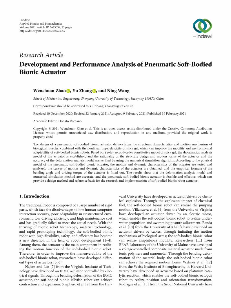
2.1. Structure Design. The pneumatic soft-bodied bionic actu-ator is shown in Figure 1. Its structure is mainly composed ofthree pneumatic network devices, a nonretractable columnstructure, and a compression spring structure. Each actuatingunit is composed of a pneumatic network device, a nonre-tractable column structure, and a compression spring struc-ture, and each pneumatic network device is composed of 13driving cavity structures. Besides, in order to enhance thestructural strength, execution force, and motion restoringforce of the actuator, the compression spring structure isembedded in the inner part of the nonretractable column.
The main structural parameters of the actuator are shownin Table 1. It should be noted that in order to ensure the
2 Applied Bionics and Biomechanics
interaction between the driving cavity structures of actuator,the other walls of the driving cavity structures are required tobe thicker than the expansion walls.
2.2. Analysis of Motion Forms. The motion process of thepneumatic soft-bodied bionic actuator can be divided intotwo parts: the middle part periodic bending and the left andright sides periodic bending. In the middle part periodicbending motion stage, when the air pump inflates the innerpart of the middle part actuating unit of the actuator, drivingcavity structures to interact with each other, resulting in theexpansion and bending deformation of the middle part ofthe actuator, as shown in Figure 2(a). In the left side periodicbending motion stage, when the air pump inflates the left sideactuating unit of the actuator, the left side of the actuator willexpand and bend due to the interaction of the driving cavitystructures, as shown in Figure 2(b). In the right side periodicbending motion stage, when the air pump inflates into theright side actuating unit of the actuator, the right side of theactuator will expand and bend due to the interaction of thedriving cavity structures, as shown in Figure 2(c).
3. Mechanical Model Analysis
3.1. Constitutive Model of Silica Gel Material. The pneumaticsoft-bodied bionic actuator is mainly composed of silica gelmaterial, which has the characteristics of hyperelasticityand the capability of large deformation. There exists a highlynonlinear relationship between its strain and stress. In orderto ensure the reliability of the research results, the phenome-nological theory is used to describe its mechanical properties.The common constitutive models of silica gel materials arethe Mooney Rivlin model, Ogden model, Yeoh model, etc.
[34–38]. Among them, the Yeoh model has good adaptabilityin the range of 300% deformation, which is the first choice foranalyzing the deformation of silica gel.
Based on the stress-strain theory, the constitutive relationof silica gel material is established, and it is assumed that thesilica gel material is isotropic and incompressible. Equation(1) of the strain energy function is as follows:
W =W I1, I2, I3ð Þ,I1 = λ21 + λ22 + λ23,I2 = λ21λ
22 + λ22λ
23 + λ21λ
23,
I3 = λ21λ22λ
23,
8>>>>><>>>>>:
ð1Þ
where I1, I2, and I3 are the invariants of the deformationtensor; λ1, λ2, and λ3 are the main elongation ratio in threedirections of space; and W is the strain energy function.
According to the isotropy and incompressibility of thematerials, Equation (2) is listed as follows:
I3 = λ21λ22λ
23 = 1: ð2Þ
During the expansion of the driving cavity structure, theexpansion wall will not only elongate but also will becomethinner. So, it is necessary to assume that the expansion walldoes not deform in the width direction, that is, λ3 = 1.Therefore, according to the incompressibility of the materialconstitutive model, Equation (3) is listed as follows:
λ22 =1λ21
: ð3Þ
(a)
t
h
al
(b) (c)
Figure 1: Structure diagram of pneumatic soft-bodied bionic actuator. (a) Overall structure of actuator. (b) Partial view of actuator crosssection. (c) End view of actuator.
Table 1: Main structural parameters of actuator.
No. Size Numerical values
1 Driving cavity structure internal height h 35mm
2 Driving cavity structure expansion wall thicknesst 2mm
3 Driving cavity structure expansion wall bottom height ha 8mm
4 Nonretractable column structure thickness a 16mm
5 Nonretractable column structure length l 160mm
6 Driving cavity structure number N 13
3Applied Bionics and Biomechanics

The deformation tensor can be expressed as in
I1 = I2 = λ21 +1λ21
+ 1: ð4Þ
Based on the most typical second-order parameters formof the Yeoh model, Equation (5) of the strain energy densityfunction model is expressed as
W = C10 I1 − 3ð Þ + C20 I1 − 3ð Þ2
= C10 λ1 −1λ1
� �2+ C20 λ1 −
1λ1
� �4,
ð5Þ
where Cij is the dimensionless relationship constant, C10 =0:09, C20 = 0:02.
Combining Equation (1) to Equation (5), the expressionof principal stress can be derived from the Piola-Kirchhoffstress and Cauchy-Green strain relationship, and thus, Equa-tion (6) is listed as follows:
σij =2λ1
λ21‐1
λ21λ22
� �∂W∂I1
+ λ22∂W∂I2
� �: ð6Þ
Substituting formula Equation (3) to Equation (5) intoEquation (6), the relationship between stress and the mainelongation ratio, i.e., Equation (7) is listed as follows:
σ = λ41‐1λ31
2C1 + 4C2 λ1 −1λ1
� �2 !
: ð7Þ
3.2. Establishment of Mechanical Model. It is difficult tomodel the pneumatic soft-bodied bionic actuator, so it is nec-essary to simplify it properly in the nonlinear mechanicalanalysis. Since the actuator is composed of three identicalactuating units arranged at equal angles, and driven in differ-ent time sequences according to the specific operationrequirements, the equivalent bending deformation diagramcan be obtained by taking the inflation of a single actuatingunit as an example for theoretical modeling, as shown inFigure 3. Among them, the overall bending angle is indicated
byΦ, and the bending angle of the single driving cavity struc-ture is indicated by θ.
According to Figure 3, the overall bending angle is theresult of the bending superposition of each driving cavitystructure, and the relationship between the overall bendingangle Φ and θ can be expressed as in
Φ = 13θ: ð8Þ
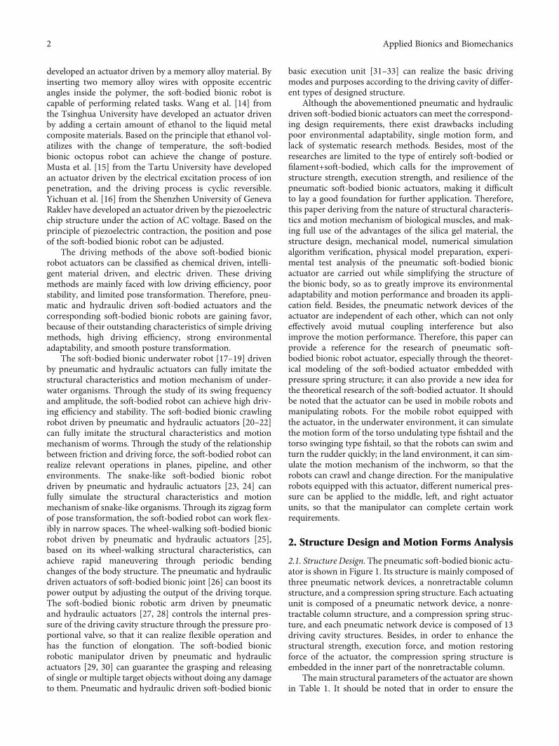
Then, the structure of a single driving cavity is researched,and the equivalent model of the initial state and expansiondeformation state is obtained, as shown in Figure 4.
When the expansion wall expands outwards under theaction of inflation pressure P, the lateral distance of expan-sion is ta.
The bending angle θ of a single driving cavity structurecan be expressed as in
θ = 2 arctan tah‐hað Þ/2ð Þ + ha
� �: ð9Þ
Then, take the bottom end of the expansion wall of thedriving cavity structure as the coordinate origin, and thus,the coordinate system is established, as shown in Figure 5.Among them, the center angle formed by the bulge of theexpansion wall is δ, the radius of the arc is R, the height ofthe expansion wall elongates from h to the arc length hb afterinflation, and the center coordinate is ðx0, y0Þ.
(a) (b) (c)
Figure 2: Periodic motion process diagram of pneumatic soft-bodied bionic actuator. (a) Middle part bending, (b) Left side bending. (c) Rightside bending.
𝜃
𝛷
Figure 3: Expansion equivalent diagram.
4 Applied Bionics and Biomechanics
Then, the relation between hb and h is expressed as in
hb = λ1h: ð10Þ
In the established coordinate system, the arc of theexpansion wall can be expressed as in
y =ffiffiffiffiffiffiffiffiffiffiffiffiffiffiffiffiffiffiffiffiffiffiffiffiffiffiffiR2 − x − x0ð Þ2
q+ y0, ð11Þ
Then, according to the geometric relationship, Equation(12) is obtained as follows:
x0 =h‐ha2 ,
y0 = −R cos δ
2
� �,
R = h‐ha2 ⋅ sin δ/2ð Þ :
8>>>>>>>><>>>>>>>>:
ð12Þ
It can be expressed as in
yh‐ha2
� �=
ffiffiffiffiffiffiffiffiffiffiffiffiffiffiffiffiffiffiffiffiffiffiffiffiffiffiffiffiffiffiffiffiffiffiffiffiffiR2 −
h‐ha2 − x0
� �2s
+ y0 = y δð Þ: ð13Þ
Combining Equation (8) to Equation (13), the relation-ship between Φ and δ can be obtained as in
Φ =Φ δð Þ: ð14Þ
Through the relationship between the inflation pressureP and the center angle δ of the expansion wall bulge, the rela-tionship between the inflation pressure P and the overallbending angle Φ is obtained. Then, assuming that the infla-tion pressure increases from 0 to P, and the deformation ofeach point on the expansion wall increases linearly toyðxÞ,the work done by the pressure at each point on the side wallto the side wall can be expressed as in
U = 26ðhb0P ⋅ y xð Þdx = 26P
ðλ1h0
ffiffiffiffiffiffiffiffiffiffiffiffiffiffiffiffiffiffiffiffiffiffiffiffiffiffiffiR2 − x − x0ð Þ2
q+ y0
� �dx =U P, δð Þ:
ð15Þ
The main elongation λ1 is expressed by δ, as in
λ1 =δ
2 ⋅ sin δ/2ð Þ : ð16Þ
Taking Equation (3) to Equation (5) into consideration,the function of strain energy density can be expressed as afunction of δ, as in
W =W δð Þ: ð17Þ
The deformation energy of the expansion wall afterdeformation can be expressed as in
V = 26t ⋅ h‐hað Þ ⋅W δð Þ = V δð Þ: ð18Þ
The deformation energy of the nonretractable columncorresponding to the deformation of the expansion wall canbe expressed as in
E = l ⋅ a ⋅W δð Þ = E δð Þ: ð19Þ
t
h
ha
(a)
ta
P
𝜃
(b)
Figure 4: Equivalent diagram of a single driving cavity structure. (a) Initial state. (b) Deformation state.
R
y
x
hb
Figure 5: Coordinate system of a single driving cavity structure.
5Applied Bionics and Biomechanics
The work done by the compression spring correspondingto the deformation of the expansion wall is
E1 δð Þ = 12a kl
2, ð20Þ
where k is the elasticity coefficient, the value is 1.1.According to the law of conservation of energy, the work
done at each point on the expansion wall is equal to thedeformation energy of the side wall of the driving cavitystructure, and therefore, Equation (21) is listed as follows:
V δð Þ =U P, δð Þ‐E δð Þ‐E1 δð Þ: ð21Þ
Combining Equation (14) and Equation (21) can furtherderive the function expression between the bending angle Φand the inflation pressure P; this paper does not need to elab-orate but uses Equation (22) to express it.
Φ =Φ Pð Þ: ð22Þ
4. Numerical Simulation AlgorithmVerificationand Physical Model Preparation
4.1. Verification of Numerical Simulation Algorithm. Basedon Yeoh’s second-order constitutive model of silica gel mate-rial for the pneumatic soft-bodied bionic actuator, the ratio-nality of structural design and motion forms and theaccuracy of the theoretical model of deformation analysisare verified by the numerical simulation algorithm [39–41].The calculation results obtained from the numerical simula-tion algorithm are shown in Figure 6.
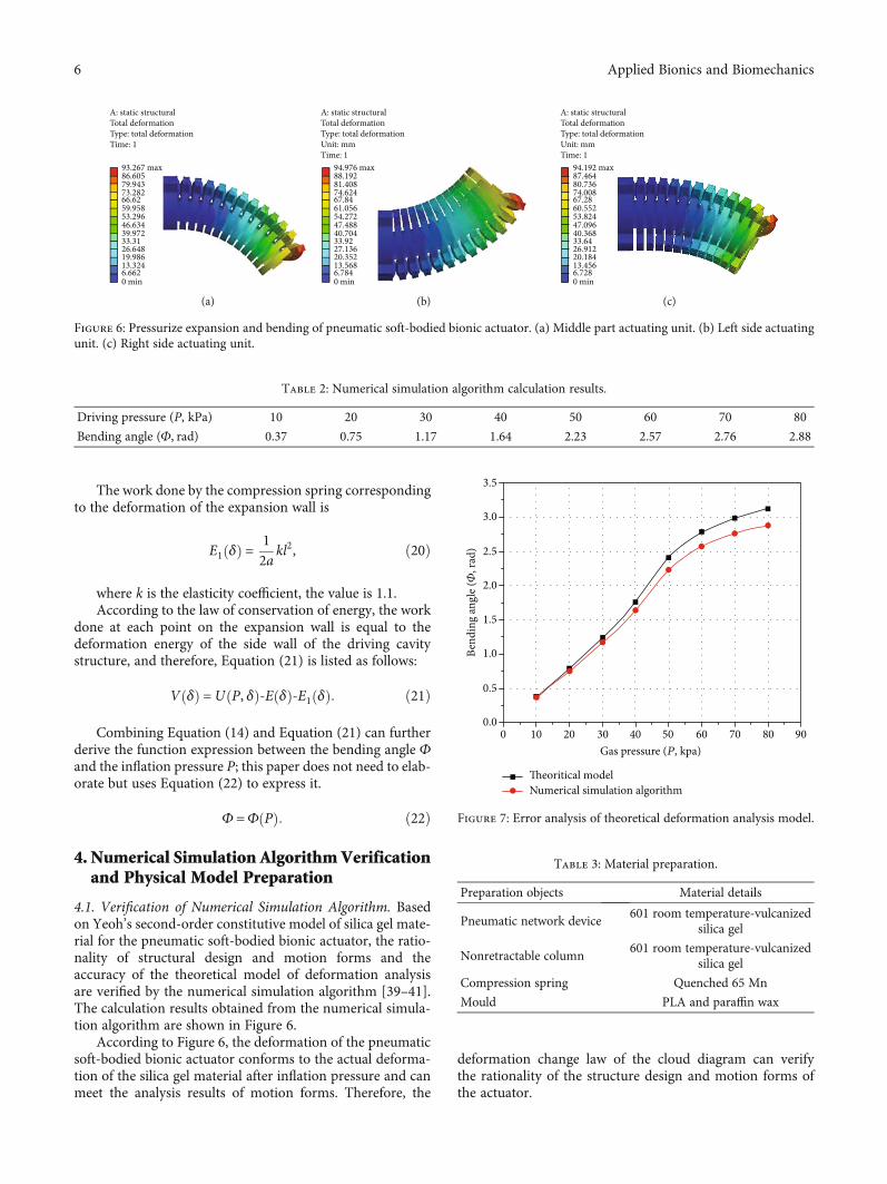
According to Figure 6, the deformation of the pneumaticsoft-bodied bionic actuator conforms to the actual deforma-tion of the silica gel material after inflation pressure and canmeet the analysis results of motion forms. Therefore, the
deformation change law of the cloud diagram can verifythe rationality of the structure design and motion forms ofthe actuator.
A: static structuralTotal deformationType: total deformationTime: 1
93.267 max86.60579.94373.28266.6259.95853.29646.63439.97233.3126.64819.98613.3246.6620 min
(a)
94.976 max88.19281.40874.62467.8461.05654.27247.48840.70433.9227.13620.35213.5686.7840 min
A: static structuralTotal deformationType: total deformationUnit: mmTime: 1
(b)
94.192 max87.46480.73674.00867.2860.55253.82447.09640.36833.6426.91220.18413.4566.7280 min
A: static structuralTotal deformationType: total deformationUnit: mmTime: 1
(c)
Figure 6: Pressurize expansion and bending of pneumatic soft-bodied bionic actuator. (a) Middle part actuating unit. (b) Left side actuatingunit. (c) Right side actuating unit.
Table 2: Numerical simulation algorithm calculation results.
Driving pressure (P, kPa) 10 20 30 40 50 60 70 80
Bending angle (Φ, rad) 0.37 0.75 1.17 1.64 2.23 2.57 2.76 2.88
3.5
3.0
2.5
2.0
1.5
1.0
0.5
0.00 10 20 30 40
Gas pressure (P, kpa)
Theoritical modelNumerical simulation algorithm
Bend
ing
angl
e (𝛷
, rad
)
50 60 70 80 90
Figure 7: Error analysis of theoretical deformation analysis model.
Table 3: Material preparation.
Preparation objects Material details
Pneumatic network device601 room temperature-vulcanized
silica gel
Nonretractable column601 room temperature-vulcanized
silica gel
Compression spring Quenched 65 Mn
Mould PLA and paraffin wax
6 Applied Bionics and Biomechanics
It should be noted that the theoretical model of deforma-tion analysis is based on the simplified equivalent bendingdeformation of the actuator, which is more similar to thedeformation and bending of the middle part actuating unitof the actuator. Therefore, the theoretical model is verifiedby the numerical simulation results of deformation andbending of the middle part actuating unit of the actuator,and the numerical simulation algorithm calculation resultsunder different driving pressures from 10 kPa to 80 kPa areobtained, as shown in Table 2.
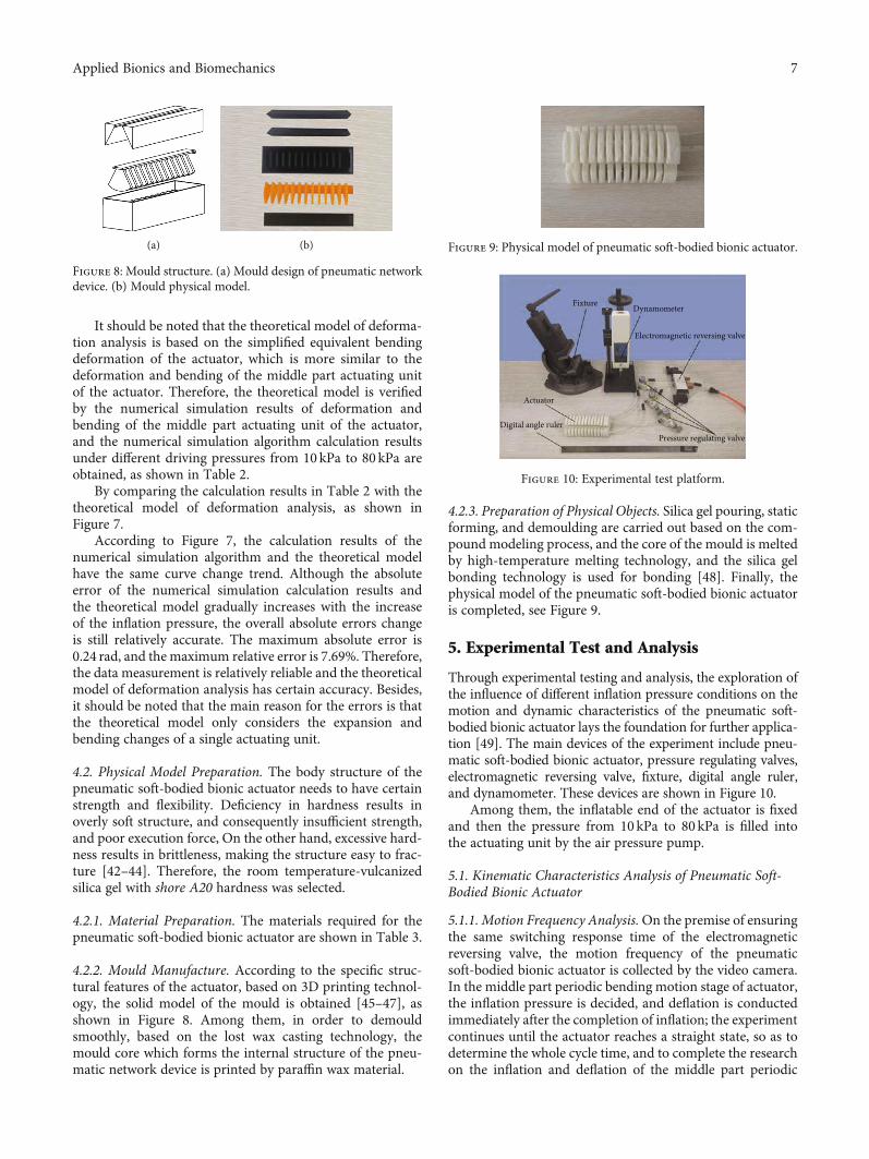
By comparing the calculation results in Table 2 with thetheoretical model of deformation analysis, as shown inFigure 7.
According to Figure 7, the calculation results of thenumerical simulation algorithm and the theoretical modelhave the same curve change trend. Although the absoluteerror of the numerical simulation calculation results andthe theoretical model gradually increases with the increaseof the inflation pressure, the overall absolute errors changeis still relatively accurate. The maximum absolute error is0.24 rad, and the maximum relative error is 7.69%. Therefore,the data measurement is relatively reliable and the theoreticalmodel of deformation analysis has certain accuracy. Besides,it should be noted that the main reason for the errors is thatthe theoretical model only considers the expansion andbending changes of a single actuating unit.
4.2. Physical Model Preparation. The body structure of thepneumatic soft-bodied bionic actuator needs to have certainstrength and flexibility. Deficiency in hardness results inoverly soft structure, and consequently insufficient strength,and poor execution force, On the other hand, excessive hard-ness results in brittleness, making the structure easy to frac-ture [42–44]. Therefore, the room temperature-vulcanizedsilica gel with shore A20 hardness was selected.
4.2.1. Material Preparation. The materials required for thepneumatic soft-bodied bionic actuator are shown in Table 3.
4.2.2. Mould Manufacture. According to the specific struc-tural features of the actuator, based on 3D printing technol-ogy, the solid model of the mould is obtained [45–47], asshown in Figure 8. Among them, in order to demouldsmoothly, based on the lost wax casting technology, themould core which forms the internal structure of the pneu-matic network device is printed by paraffin wax material.
4.2.3. Preparation of Physical Objects. Silica gel pouring, staticforming, and demoulding are carried out based on the com-pound modeling process, and the core of the mould is meltedby high-temperature melting technology, and the silica gelbonding technology is used for bonding [48]. Finally, thephysical model of the pneumatic soft-bodied bionic actuatoris completed, see Figure 9.
5. Experimental Test and Analysis
Through experimental testing and analysis, the exploration ofthe influence of different inflation pressure conditions on themotion and dynamic characteristics of the pneumatic soft-bodied bionic actuator lays the foundation for further applica-tion [49]. The main devices of the experiment include pneu-matic soft-bodied bionic actuator, pressure regulating valves,electromagnetic reversing valve, fixture, digital angle ruler,and dynamometer. These devices are shown in Figure 10.
Among them, the inflatable end of the actuator is fixedand then the pressure from 10kPa to 80 kPa is filled intothe actuating unit by the air pressure pump.
5.1. Kinematic Characteristics Analysis of Pneumatic Soft-Bodied Bionic Actuator
5.1.1. Motion Frequency Analysis.On the premise of ensuringthe same switching response time of the electromagneticreversing valve, the motion frequency of the pneumaticsoft-bodied bionic actuator is collected by the video camera.In the middle part periodic bending motion stage of actuator,the inflation pressure is decided, and deflation is conductedimmediately after the completion of inflation; the experimentcontinues until the actuator reaches a straight state, so as todetermine the whole cycle time, and to complete the researchon the inflation and deflation of the middle part periodic
(a) (b)
Figure 8: Mould structure. (a) Mould design of pneumatic networkdevice. (b) Mould physical model.
Figure 9: Physical model of pneumatic soft-bodied bionic actuator.
Fixture Dynamometer
Electromagnetic reversing valve
Pressure regulating valve
Actuator
Digital angle ruler
Figure 10: Experimental test platform.
7Applied Bionics and Biomechanics
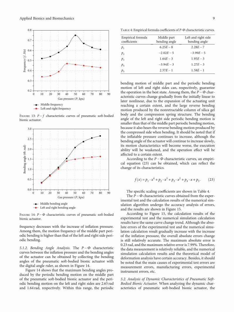
bending motion of the actuator, as shown in Figure 11(a). Inthe left and right side periodic bending motion stage of actu-ator, first the inflation pressure of actuator on one side isdetermined, and after inflation completes, it is deflatedimmediately, while the other side of actuator inflates. Afterinflation, the actuator deflates immediately until the end ofdeflation and the actuator reaches a straight state, as shownin Figure 11(b).
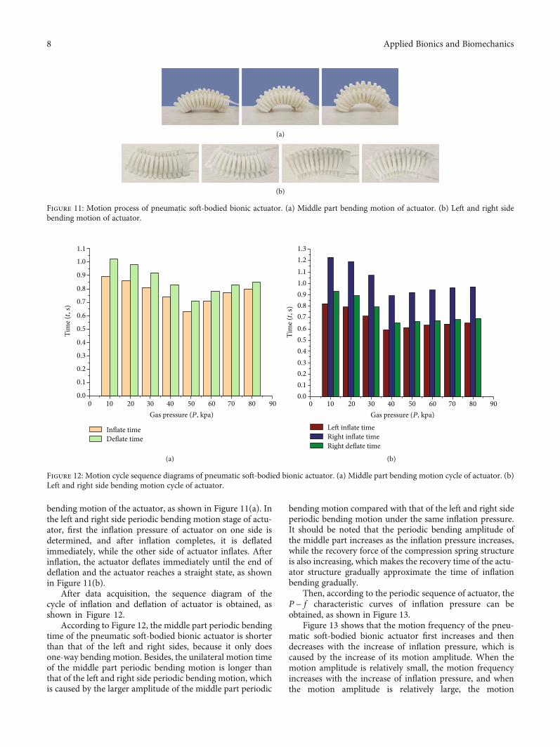
After data acquisition, the sequence diagram of thecycle of inflation and deflation of actuator is obtained, asshown in Figure 12.
According to Figure 12, the middle part periodic bendingtime of the pneumatic soft-bodied bionic actuator is shorterthan that of the left and right sides, because it only doesone-way bending motion. Besides, the unilateral motion timeof the middle part periodic bending motion is longer thanthat of the left and right side periodic bending motion, whichis caused by the larger amplitude of the middle part periodic
bending motion compared with that of the left and right sideperiodic bending motion under the same inflation pressure.It should be noted that the periodic bending amplitude ofthe middle part increases as the inflation pressure increases,while the recovery force of the compression spring structureis also increasing, which makes the recovery time of the actu-ator structure gradually approximate the time of inflationbending gradually.
Then, according to the periodic sequence of actuator, theP − f characteristic curves of inflation pressure can beobtained, as shown in Figure 13.
Figure 13 shows that the motion frequency of the pneu-matic soft-bodied bionic actuator first increases and thendecreases with the increase of inflation pressure, which iscaused by the increase of its motion amplitude. When themotion amplitude is relatively small, the motion frequencyincreases with the increase of inflation pressure, and whenthe motion amplitude is relatively large, the motion
(a)
(b)
Figure 11: Motion process of pneumatic soft-bodied bionic actuator. (a) Middle part bending motion of actuator. (b) Left and right sidebending motion of actuator.
1.1
1.0
0.9
0.8
0.7
0.6
0.5
0.4
0.3
0.2
0.1
0.00 10 20 30 40 50 60 70 80 90
Tim
e (t,
s)
Gas pressure (P, kpa)
(a)
1.11.21.3
1.00.90.80.70.6
Tim
e (t,
s)
0 10 20 30 40 50 60 70 80 90Gas pressure (P, kpa)
0.50.40.30.20.10.0
(b)
Figure 12: Motion cycle sequence diagrams of pneumatic soft-bodied bionic actuator. (a) Middle part bending motion cycle of actuator. (b)Left and right side bending motion cycle of actuator.
8 Applied Bionics and Biomechanics
frequency decreases with the increase of inflation pressure.Among them, the motion frequency of the middle part peri-odic bending is higher than that of the left and right side peri-odic bending.
5.1.2. Bending Angle Analysis. The P −Φ characteristiccurves between the inflation pressure and the bending anglesof the actuator can be obtained by collecting the bendingangles of the pneumatic soft-bodied bionic actuator withthe digital angle ruler, as shown in Figure 14.
Figure 14 shows that the maximum bending angles pro-duced by the periodic bending motion on the middle partof the pneumatic soft-bodied bionic actuator and the peri-odic bending motion on the left and right sides are 2.65 radand 1.64 rad, respectively. Within this range, the periodic
bending motion of middle part and the periodic bendingmotion of left and right sides can, respectively, guaranteethe operation in the best state. Among them, the P −Φ char-acteristic curves change gradually from the initially linear tolater nonlinear, due to the expansion of the actuating unitreaching a certain extent, and the large reverse bendingmotion produced by the nonretractable column of silica gelbody and the compression spring structure. The bendingangle of the left and right side periodic bending motion issmaller than that of the middle part periodic bending motion,because it also bears the reverse bending motion produced bythe compressed side when bending. It should be noted that ifthe inflatable pressure continues to increase, although thebending angle of the actuator will continue to increase slowly,its motion characteristics will become worse, the executionability will be weakened, and the operation effect will beaffected to a certain extent.
According to the P −Φ characteristic curves, an empiri-cal equation (23) can be obtained, which can reflect thechange of its characteristics.
f xð Þ = p1 ⋅ x4 + p2 ⋅ x
3 + p3 ⋅ x2 + p4 ⋅ x + p5: ð23Þ
The specific scaling coefficients are shown in Table 4.The P −Φ characteristic curves obtained from the exper-
imental test and the calculation results of the numerical sim-ulation algorithm undergo the accuracy analysis of errors,and the results are shown in Figure 15.
According to Figure 15, the calculation results of theexperimental test and the numerical simulation calculationresults have the same curve change trend. Although the abso-lute errors of the experimental test and the numerical simu-lation calculation result gradually increase with the increaseof the inflation pressure, the overall absolute errors changeis still relatively accurate. The maximum absolute error is0.23 rad, and the maximum relative error is 7.99%. Therefore,the data measurement is relatively reliable, and the numericalsimulation calculation results and the theoretical model ofdeformation analysis have certain accuracy. Besides, it shouldbe noted that the main causes of experimental test errors aremeasurement errors, manufacturing errors, experimentalinstrument errors, etc.
5.2. Analysis of Dynamic Characteristics of Pneumatic Soft-Bodied Bionic Actuator. When analyzing the dynamic char-acteristics of pneumatic soft-bodied bionic actuator, the
3.0
2.5
2.0
1.5
1.0
0.5
0.0
Bend
ing
angl
e (, r
ad)
0 10 20 30 40Gas pressure (P, kpa)
Middle bending angle
50 60 70 80 90
Figure 14: P −Φ characteristic curves of pneumatic soft-bodiedbionic actuator.
Table 4: Empirical formula coefficients of P‐Φ characteristic curves.
Empirical formulacoefficients
Middle partbending angle
Left and right sidebending angle
p1 6:25E − 8 2:28E − 7p2 −2:02E − 5 −3:99E − 5p3 1:64E − 3 1:95E − 3p4 −3:94E − 3 1:27E − 3p5 2:57E − 1 1:58E − 1
Middle frequencyLeft and right frequency
00.2
0.3
0.4
0.5
0.6
Freq
uenc
y (f
, Hz)
0.7
0.8
10 20 30 40Gas pressure (P, kpa)
50 60 70 80 90
Figure 13: P − f characteristic curves of pneumatic soft-bodiedbionic actuator.
9Applied Bionics and Biomechanics

driving torque is collected by dynamometer, as shown inFigure 16.
5.2.1. Dynamic Characteristic Analysis of Variable BendingAngle. The bending angle of the actuator is variable; the P−M characteristic curves of inflation pressure and drivingtorque are obtained, as shown in Figure 17.
Figure 17 shows that the driving torque values of the leftand right side periodic bending of the pneumatic soft-bodiedbionic actuator is relatively lower compared with that of themiddle part periodic bending, which is caused by the countertorque produced by the compressed side cavity structure. Itshould be noted that the variation trend of the P −M charac-teristic curves is similar to that of the P −Φ characteristiccurves, which indicates that the driving torque is closelyrelated to the bending angle. In addition, with the increaseof inflation pressure, the nonlinear change is partly due tothe extreme deformation of the actuator body structure,which leads to the change of its stress form.
The P −M characteristic curves are expressed by theempirical equation (23), and the specific scale coefficientsare shown in Table 5.
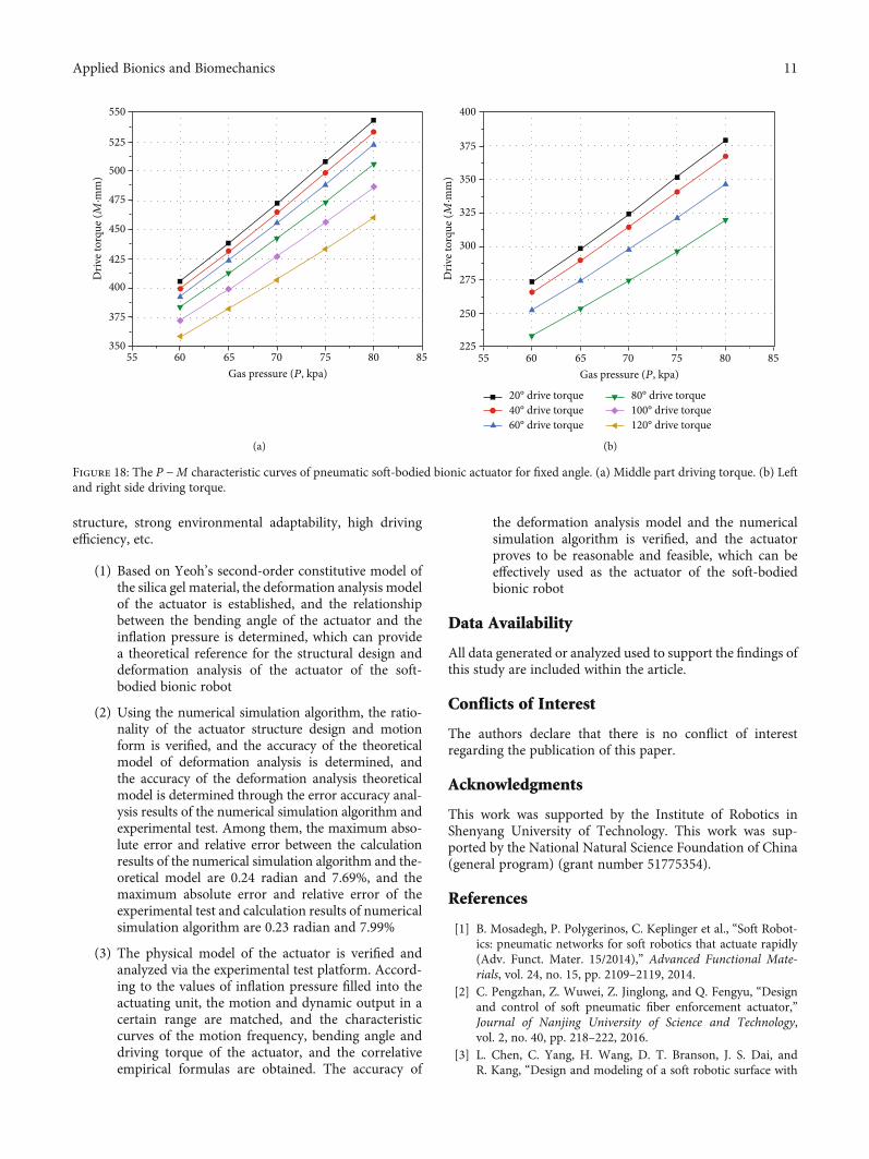
5.2.2. Dynamic Characteristic Analysis of Fixed BendingAngle. The bending angle of the actuator is fixed; the P −Mcharacteristic curves of inflation pressure and driving torqueare obtained, as shown in Figure 18.
According to Figure 18, the middle part driving torquesof the actuator and the left and right sides both increase lin-early with the increase of the inflation pressure. It should benoted that the middle part driving torque of the actuator islarger than that of the left and right sides, because the leftand right sides need to bear the reverse bending motion pro-duced by the compressed side when bending; this phenome-non can correspond to the above test results.
6. Conclusions
This paper designs a kind of pneumatic soft-bodied bionicactuator, which is suitable for robot carriers of underwaterswimming and land crawling. It has the advantages of simple
Figure 16: Driving torque measure experiment of pneumatic soft-bodied bionic actuator.
400
350
300
250
200
150
50
100
00 10 20 30 40
Gas pressure (P, kpa)
Middle drive torque
Driv
e tor
que (M
·mm
)
50 60 70 80 90
Figure 17: P‐M characteristic curves of pneumatic soft-bodiedbionic actuator for variable angle.
Table 5: Empirical formula coefficients of P −M characteristiccurves.
Empirical formulacoefficients
Middle partbending angle
Left and right sidebending angle
p1 9:36E − 6 3:26E − 5p2 −2:99E − 3 −5:72E − 3p3 2:43E − 1 2:79E − 1p4 −7:80E − 1 −2:02E − 1p5 38:29 22:7
3.0
2.5
2.0
1.5
1.0
0.5
0.00 10 20 30 40
Gas pressure (P, kpa)
Experimental testNumerical simulation algorithm
Bend
ing
angl
e (, r
ad)
50 60 70 80 90
Figure 15: Errors analysis of numerical simulation deformationmodel.
10 Applied Bionics and Biomechanics
structure, strong environmental adaptability, high drivingefficiency, etc.
(1) Based on Yeoh’s second-order constitutive model ofthe silica gel material, the deformation analysis modelof the actuator is established, and the relationshipbetween the bending angle of the actuator and theinflation pressure is determined, which can providea theoretical reference for the structural design anddeformation analysis of the actuator of the soft-bodied bionic robot
(2) Using the numerical simulation algorithm, the ratio-nality of the actuator structure design and motionform is verified, and the accuracy of the theoreticalmodel of deformation analysis is determined, andthe accuracy of the deformation analysis theoreticalmodel is determined through the error accuracy anal-ysis results of the numerical simulation algorithm andexperimental test. Among them, the maximum abso-lute error and relative error between the calculationresults of the numerical simulation algorithm and the-oretical model are 0.24 radian and 7.69%, and themaximum absolute error and relative error of theexperimental test and calculation results of numericalsimulation algorithm are 0.23 radian and 7.99%
(3) The physical model of the actuator is verified andanalyzed via the experimental test platform. Accord-ing to the values of inflation pressure filled into theactuating unit, the motion and dynamic output in acertain range are matched, and the characteristiccurves of the motion frequency, bending angle anddriving torque of the actuator, and the correlativeempirical formulas are obtained. The accuracy of
the deformation analysis model and the numericalsimulation algorithm is verified, and the actuatorproves to be reasonable and feasible, which can beeffectively used as the actuator of the soft-bodiedbionic robot
Data Availability
All data generated or analyzed used to support the findings ofthis study are included within the article.
Conflicts of Interest
The authors declare that there is no conflict of interestregarding the publication of this paper.
Acknowledgments
This work was supported by the Institute of Robotics inShenyang University of Technology. This work was sup-ported by the National Natural Science Foundation of China(general program) (grant number 51775354).
References
[1] B. Mosadegh, P. Polygerinos, C. Keplinger et al., “Soft Robot-ics: pneumatic networks for soft robotics that actuate rapidly(Adv. Funct. Mater. 15/2014),” Advanced Functional Mate-rials, vol. 24, no. 15, pp. 2109–2119, 2014.
[2] C. Pengzhan, Z. Wuwei, Z. Jinglong, and Q. Fengyu, “Designand control of soft pneumatic fiber enforcement actuator,”Journal of Nanjing University of Science and Technology,vol. 2, no. 40, pp. 218–222, 2016.
[3] L. Chen, C. Yang, H. Wang, D. T. Branson, J. S. Dai, andR. Kang, “Design and modeling of a soft robotic surface with
550
525
500
475
450
425
375
400
350
Driv
e tor
que (M
·mm
)
55 60 65Gas pressure (P, kpa)
70 75 80 85
(a)
55 60 65Gas pressure (P, kpa)
70 75 80 85
400
375
350
325
300
250
275
225
Driv
e tor
que (M
·mm
)
20° drive torque40° drive torque60° drive torque
80° drive torque100° drive torque120° drive torque
(b)
Figure 18: The P −M characteristic curves of pneumatic soft-bodied bionic actuator for fixed angle. (a) Middle part driving torque. (b) Leftand right side driving torque.
11Applied Bionics and Biomechanics
hyperelastic material,” Mechanism and Machine Theory,vol. 130, no. 13, pp. 109–122, 2018.
[4] A. D. Marchese, R. K. Katzschmann, and D. Rus, “A recipe forsoft fluidic elastomer robots,” Soft Robotics, vol. 2, no. 1, pp. 7–25, 2015.
[5] S. I. Rich, R. J. Wood, and C. Majidi, “Untethered soft robot-ics,” Nature Electronics, vol. 1, no. 2, pp. 102–112, 2018.
[6] S. W. Yeom and I. K. Oh, “A biomimetic jellyfish robot basedon ionic polymer metal composite actuators,” Smart MaterialStructures, vol. 18, no. 8, pp. 085002–085092, 2009.
[7] J. Najem and D. J. Leo, A bio-inspired bell kinematics design ofa jellyfish robot using ionic polymer metal composites actuators,Proc SPIE, 2012.
[8] R. F. Shepherd, A. A. Stokes, J. Freake et al., “Using explosionsto power a soft robot,” Angewandte Chemie International Edi-tion, vol. 52, no. 10, pp. 2892–2896, 2013.
[9] A. A. Villanueva, K. J. Marut, T. Michael, and S. Priya, “Biomi-metic autonomous robot inspired by theCyanea capillata(-Cyro),” Bioinspiration & Biomimetics, vol. 8, no. 4,pp. 046005–046055, 2013.
[10] F. Renda, M. Giorelli, M. Calisti, M. Cianchetti, and C. Laschi,“Dynamic model of a multibending soft robot arm driven bycables,” IEEE Transactions on Robotics, vol. 30, no. 5,pp. 1109–1122, 2014.
[11] Y. Bahramzadeh and M. Shahinpoor, “A review of ionic poly-meric soft actuators and sensors,” Soft Robotics, vol. 1, no. 1,pp. 38–52, 2014.
[12] M. Wehner, R. L. Truby, D. J. Fitzgerald et al., “An integrateddesign and fabrication strategy for entirely soft, autonomousrobots,” Nature, vol. 536, no. 7617, pp. 451–455, 2016.
[13] H. Rodrigue, W. Wang, M. W. Han, Y. J. Quan, and S. H. Ahn,“Comparison of mold designs for SMA-based twisting softactuator,” Sensors and Actuators A: Physical, vol. 237, no. 7,pp. 96–106, 2016.
[14] H.Wang, Y. Yao, X.Wang et al., “Large-magnitude transform-able liquid-metal composites,” ACS Omega, vol. 4, no. 1,pp. 2311–2319, 2019.
[15] I. Must, E. Sinibaldi, and B. Mazzolai, “A variable-stiffnesstendril-like soft robot based on reversible osmotic actuation,”Nature Communications, vol. 10, no. 1, pp. 1–9, 2019.
[16] Y. Wu, J. K. Yim, J. Liang et al., “Insect-scale fast moving andultrarobust soft robot,” Science robotics, vol. 4, no. 32, pp. -eaax1594–eaax1611, 2019.
[17] A. D. Marchese, C. D. Onal, and D. Rus, “Autonomous softrobotic fish capable of escape maneuvers using fluidic elasto-mer actuators,” Soft Robotics, vol. 1, no. 1, pp. 75–87, 2014.
[18] A. Jusufi, D. M. Vogt, R. J. Wood, and G. V. Lauder, “Undula-tory swimming performance and body stiffness modulation ina soft robotic fish-inspired physical model,” Soft Robotics,vol. 4, no. 3, pp. 202–210, 2017.
[19] J. Frame, N. Lopez, O. Curet, and E. D. Engeberg, “Thrust forcecharacterization of free-swimming soft robotic jellyfish,”Bioinspiration & Biomimetics, vol. 13, no. 6, pp. 26–44, 2018.
[20] M. T. Tolley, R. F. Shepherd, B. Mosadegh et al., “A resilient,untethered soft robot,” Soft Robotics, vol. 1, no. 3, pp. 213–223, 2014.
[21] S. Yanqiong, P. Wu, and Y. Wenbo, “Movement of air-drivensoft robot,” Journal of Mechanical Engineering, vol. 53, no. 13,pp. 14–18, 2017.
[22] S. Liming, L. Tingyu, and X. I. Zuoyan, “Analysis and experi-ment of actuating method for pneumatic soft crawling robot,”
Chinese Hydraulic & Pneumatics, vol. 1, no. 11, pp. 99–103,2018.
[23] M. J. Bishop and S. Kota, “Towards snake-like soft robots:design of fluidic fiber-reinforced elastomeric helical manipula-tors,” in 2013 IEEE/RSJ International Conference on IntelligentRobots and Systems, Tokyo, Japan, 2013.
[24] M. Luo, W. Tao, F. Chen, T. K. Khuu, S. Ozel, and C. D. Onal,“Design improvements and dynamic characterization on flu-idic elastomer actuators for a soft robotic snake,” in 2014 IEEEInternational Conference on Technologies for Practical RobotApplications (TePRA), Woburn, MA, USA, 2014.
[25] Y. Jiantao, C. Xinbo, C. Juntao, Z. Hong, L. Haili, andZ. Yongsheng, “Design and motion analysis of a wheel-walking bionic soft robot,” Journal of Mechanical Engineering,vol. 55, no. 5, pp. 27–35, 2019.
[26] F. Jizhuang, Y. Qingguo, Y. Bowen, and Z. Jie, “Development ofa joint-like pneumatic actuator applied to soft frog-inspiredswimming robot,” Robot, vol. 40, no. 5, pp. 4–12, 2018.
[27] J. B. Moser, G. Krishnan, C. Kim, and S. Kota, “Design of softrobotic actuators using fluid-filled fiber-reinforced elastomericenclosures in parallel combinations,” in IEEE/RSJ Interna-tional Conference on Intelligent Robots and Systems, Vila-moura, Portugal, 2012.
[28] A. D. Marchese, R. K. Katzschmann, and D. L. Rus, “Wholearm planning for a soft and highly compliant 2D roboticmanipulator,” in 2014 IEEE/RSJ International Conference onIntelligent Robots and Systems, Chicago, IL, USA, 2014.
[29] Y. Hao, Z. Gong, Z. Xie et al., “Universal soft pneumaticrobotic gripper with variable effective length,” in 2016 35thChinese Control Conference (CCC), Chengdu, China, 2016.
[30] Z. Wang and S. Hirai, “Soft gripper dynamics using a line-segment model with an optimization-based parameter identi-fication method,” IEEE Robotics and Automation Letters,vol. 2, no. 2, pp. 624–631, 2017.
[31] B. N. Peele, T. J. Wallin, H. Zhao, and R. F. Shepherd, “3Dprinting antagonistic systems of artificial muscle using projec-tion stereolithography,” Bioinspiration & Biomimetics, vol. 10,no. 5, pp. 45–53, 2015.
[32] S. Liming, X. Zuoyan, and L. Tingyu, “Design and fabricationof multi-chamber biomimetic pneumatic soft actuators,” Chi-nese Journal of Engineering Design, vol. 1, no. 5, pp. 31–37,2017.
[33] B. T. Phillips, K. P. Becker, S. Kurumaya et al., “A dexterous,glove-based teleoperable low-power soft robotic arm for deli-cate deep-sea biological exploration,” Scientific Reports,vol. 8, no. 1, article 14779, 2018.
[34] O. D. Yirmibesoglu, J. Morrow, S. Walker et al., “Direct 3Dprinting of silicone elastomer soft robots and their perfor-mance comparison with molded counterparts,” in 2018 IEEEInternational Conference on Soft Robotics (RoboSoft), Livorno,Italy, 2018.
[35] Y. Mei, B. Stover, N. Afsar Kazerooni et al., “A comparativestudy of two constitutive models within an inverse approachto determine the spatial stiffness distribution in soft materials,”International Journal of Mechanical Sciences, vol. 140, pp. 446–454, 2018.
[36] S. K. Panda and M. L. Buist, “A finite nonlinear hyper-viscoelastic model for soft biological tissues,” Journal of Biome-chanics, vol. 69, pp. 121–128, 2018.
[37] K. Matouš, M. G. D. Geers, V. G. Kouznetsova, andA. Gillman, “A review of predictive nonlinear theories for
12 Applied Bionics and Biomechanics
multiscale modeling of heterogeneous materials,” Journal ofComputational Physics, vol. 330, no. 5, pp. 192–220, 2017.
[38] A. Chanda and C. Callaway, “Tissue anisotropy modelingusing soft composite materials,” Applied Bionics and Biome-chanics, vol. 2018, no. 18, pp. 1–9, 2018.
[39] Y. T. Kao, Y. Zhang, J. Wang, and B. L. Tai, “Bending behav-iors of 3D-printed bi-material structure: experimental studyand finite element analysis,” Additive Manufacturing, vol. 16,pp. 197–205, 2017.
[40] W. M. Chen, T. Lee, V. S. Lee, J. W. Lee, and S. J. Lee, “Effectsof internal stress concentrations in plantar soft-tissue–a pre-liminary three-dimensional finite element analysis,” MedicalEngineering & Physics, vol. 32, no. 4, pp. 324–331, 2010.
[41] S. Kindo, R. Vashistha, S. Raj, G. P. Ravishankar, and M. P.Padwale, “Selection and validation of hyperelastic finite ele-ment model for analysis of silicone rubber,” in AIP ConferenceProceedings, Thessaloniki, Greecereference, 2018.
[42] Q. Xu, J. Liu, and L. Qu, “Dynamic modeling for siliconebeams using higher-order ANCF beam elements and experi-ment investigation,” Multibody System Dynamics, vol. 46,no. 4, pp. 307–328, 2019.
[43] R. K. Katzschmann, A. D. Maille, D. L. Dorhout, and D. Rus,“Cyclic hydraulic actuation for soft robotic devices,” in 2016IEEE/RSJ International Conference on Intelligent Robots andSystems (IROS), Daejeon, South Kore, 2016.
[44] W. Wang, J. Y. Lee, H. Rodrigue, S. H. Song, W. S. Chu, andS. H. Ahn, “Locomotion of inchworm-inspired robot madeof smart soft composite (SSC),” Bioinspiration & Biomimetics,vol. 9, no. 4, pp. 46–66, 2014.
[45] M. Launhardt, N. Ebel, M. Kondruweit, M. Weyand, T. Volk,and D. Drummer, “Developing a patient individualized flexi-ble silicone implant using SLS and vacuum die casting,” inAIP Conference Proceedings, Dresden, Federal Republic ofGermany, 2019.
[46] B. S. Homberg, R. K. Katzschmann, M. R. Dogar, and D. Rus,“Haptic identification of objects using a modular soft roboticgripper,” in 2015 IEEE/RSJ International Conference on Intelli-gent Robots and Systems (IROS), Hamburg, Germany, 2015.
[47] R. K. Katzschmann, A. D. Marchese, and D. Rus, “Hydraulicautonomous soft robotic fish for 3D swimming,” in Experi-mental Robotics, pp. 405–420, Springer, Cham, 2016.
[48] Y. Staudt, C. Odenbreit, and J. Schneider, “Failure behaviour ofsilicone adhesive in bonded connections with simple geome-try,” International Journal of Adhesion and Adhesives,vol. 82, pp. 126–138, 2018.
[49] G. Agarwal, N. Besuchet, B. Audergon, and J. Paik, “Stretch-able materials for robust soft actuators towards assistive wear-able devices,” Scientific Reports, vol. 6, no. 1, pp. 324–341,2016.
13Applied Bionics and Biomechanics