Embed Size (px)
Citation preview
© copyright FACULTY of ENGINEERING ‐ HUNEDOARA, ROMANIA 139
1. K.R. AJAO, 2. A.A. LAWAL, 3. N.A. ONAOLAPO, 4. E.J. ENIAYEKAN
DEVELOPMENT AND PRELIMINARY TESTING OF A COMPRESSED LATERITE SOIL BRICK MACHINE
1‐4. DEPARTMENT OF MECHANICAL ENGINEERING, UNIVERSITY OF ILORIN, ILORIN, NIGERIA
ABSTRACT: The high demand for housing has increased the use of conventional building materials which causes various environmental problems. In order to face this challenge, there is a need to use alternative, more natural building materials using cement stabilized soil bricks. The laterite brick moulding machine is a form of hydraulic press whose design and construction was aimed at the production of cheap, affordable and highly compressed bricks from readily available clay soil (laterite) which is well suited to local weather conditions and occupancy patterns. The machine main components are a prime mover, rotary pump, two‐way control valves and the top and bottom hydraulic arm units which help to supply the vertically upward and downward compressive forces needed for the compression and compaction of the soil‐cement mixture in the moulding chamber of the machine, the top and bottom ram which are carried by the upper and lower arm respectively. The lower arm not only helps to compress the soil‐cement mixture it also gives the moulded brick its interlocking pattern and helps to eject the moulded bricks after compression with the amount of applied pressure regulated by the two‐way control valve. The compressive strength of the bricks produced did not meet the available standard and further improvement need to be carried out on the machine for better performance. KEYWORDS: Brick molding machine, hydraulic press, compressed bricks, prime mover, moulding chamber, compressive strength INTRODUCTION
Affordable housing is needed in many countries of the world especially the developing ones. In Nigeria, the need for affordable housing is especially critical considering the huge number of the populace who cannot afford decent accommodation. Among the many alternatives available for low‐cost housing production are the compressed laterite soil blocks or bricks [1].
Clay bricks were the first man‐made artificial building material. They have been extensively used since the time of the Assyrians and Babylonians throughout all ages. Brick actually is the oldest man‐made building material, invented almost ten thousand years ago. Its simplicity, strength and durability led to extensive use and gave it a dominant place in history alongside stone. Hand‐shaped, sun‐dried bricks, reinforced with such diverse materials as straw and dung were so effective that fired bricks did not appear until the third millennium [2].
In contemporary times machines have made it possible to produce higher quality bricks or blocks using soil as the basic ingredient. Sun dried uncompressed adobe bricks can be improved greatly by compressing the soil to higher densities. In some cases, compressed soil bricks come out of the machine ready to be laid in the walls without additional drying or baking. This is because the soil is compressed to very high densities.
Furthermore, the machines used to compress the soil blocks are capable of making many bricks in a short period of time that are uniform in density, shape and overall dimensions. Machines in use today include both manually operated and mechanically operated methods to compress the soil into bricks. One of the major limitations of the manual machines is that they are slow and one is limited in how much force can be applied to the bricks [3].
Adding a hydraulic ram to compress the soil provides a high level of production capacity and quality to the process and as many as 50‐60 bricks per hour can be produced from this machine. SOIL COMPOSITION AND SUITABILITY
There are three characteristics that greatly affect suitability of soil for production of bricks. These include the composition of the soil, the moisture content of the soil, and the plasticity of the soil. An ideal soil would be composed of soil with a combined clay (15‐20%) and silt (powder) content of approximately 25‐40 percent (by volume), and a sharp sand content of approximately 40‐70 percent by volume [1].
Soil moisture content can range from 4‐12% by weight, depending upon the soil mix i.e. sand and clay percentages. The plasticity of the soil is primarily a function of the clay. The higher the plasticity
ANNALS OF FACULTY ENGINEERING HUNEDOARA – International Journal Of Engineering
Tome X (Year 2012). Fascicule 2. ISSN 1584 – 2665 140
index of the soil the greater the shrink and swell characteristics at different moisture contents. More moisture causes the clay to expand over time, and drying causes the clay to shrink. Clay with plasticity indexes of up to 25 or 30 would be acceptable for most applications. Once a suitable soil mixture design and optimal moisture content are defined, bricks may be produced. However, their suitability for construction must be examined carefully, once again following established procedures for analysis [3].
Soil has a lot of undesirable characteristics such as excessive shrinkage, loss of strength at higher moisture contents etc, which makes it a poor building material. However, the strength characteristics could be improved to an acceptable level by burning the clay to produce bricks. Alternatively, similar enhancement could be obtained by stabilizing the soils with a suitable agent. Cement is an excellent agent for stabilizing the laterite soil that is often found in tropical climatic conditions. Laterite soil consists of aluminum and ferrous oxides that would have a pozzolanic reaction with Ca(OH)2 produced while cement hydrates. Thus, with a small percentage of cement, soil could be stabilized to have most of the desirable strength properties of a load bearing walling material. These properties could be further enhanced by compacting the bricks properly.
Materials especially laterite used for the production of bricks may exist in forms which may not be suitable for bricks production. For instances, soil gotten from borrow pit may contain lumps which may require crushing (pulverizing) so as to obtain a homogenous soil particle distribution. The soil after been pulverized is usually passed through a 6mm sieve in order to remove any remaining lump or stone. Also, soil gotten may contain high clay percentage which when used for production may cause cracking of the cured brick thus reducing the quality of the bricks. Before molding such soils have to be mix with an appropriate amount of fine sandy soil in order to obtain the appropriate soil‐cement mix [1]. ANALYSIS OF PROPERTIES OF BRICKS
The fineness modulus (FM) ‐ is an index number which is roughly proportional to the average size of the particles in a given aggregate. It is computed by adding the cumulative percentages coarser than each of the standard sieves (cumulative percent retain) and dividing by 100. The equation to calculate fineness modulus (FM) as shown below [1]:
100sievetheonretainedspercentageecummulativofSum
ModulusFiness = (1)
Density. Brick is produce from a mixture of cement, coarse and fine aggregates, water, and sometimes supplementary cementing materials or chemical admixtures [4]. A normal weight of brick varies from 2250 to 2800 kg/m3. The unit weight such as density of brick varies, depending on the amount and density of the aggregate, the amount of air that is entrapped or purposely entrained, and the water and cement contents, which in turn are influenced by the maximum size of the aggregate [5]. Density ρ of a solid is the ratio of its mass to the volume it occupies, referring to the equation below:
s
s
VM
=ρ (2)
sM is the mass of the solid and, sV is the volume of the solid. The bricks made with clay normally have a bulk density of 1.8–2.0 g/cm3‐utilization of sludge as brick material.
Water Absorption. Can be measured by using the equation below:
%100xaab
absorptionWater−
= (3)
where a is mass of oven dried brick, b is mass of 24 hours immersed brick. MATERIALS AND METHODS. Design Considerations
The laterite brick moulding machine can be classified as an example of a third class lever system, because its applied force (produced by a hydraulic system) is positioned between the load and the fulcrum on the top and the bottom arms.
Provided losses due to leakage of hydraulic fluid past close fittings part of the hydraulic system, losses due to friction between parts of the system and fluid, and overall losses from the input at the energy source to the output of the system during compression are negligible, the total power supplied into the hydraulic system equals power used for the compression of the brick
PowerOutputPowerInput = (4) PQpumpthebypliedsupPower Δ= (5)
Q = Volumetric flow rate of the pump
ANNALS OF FACULTY ENGINEERING HUNEDOARA – International Journal Of Engineering
© copyright FACULTY of ENGINEERING ‐ HUNEDOARA, ROMANIA 141
The joint at the fulcrum is a form of knuckle joint and the pin at the fulcrum can be analyzed by the shear, compressive, tensile and bearing stresses expressions of a knuckle joint.
Shear stress in pin:
2s
dF4
AF
πτ == (6)
But the pin undergoes double shearing
2p
s
d
F2
πτ = (7)
F = =1R Reaction at the fulcrum
pd = diameter of the pin
Compressive stress in the pin due to the top arm end:
bdR
dbF
Sp
1c == (8)
b= diameter of the eye Tensile stress in the net area of the top arm end:
b)dd(R
Spo
yt
−= (9)
Bearing stress:
)dd(b
RS
p0
fb −= (10)
fR = Vertical reaction at the fulcrum
Tensile stress in the other end of the bottom arm frame:
)D(F4
S2t ×
=π
(11)
D = diameter of the pin The burgling stress or the yield point stress determines whether the moulding chamber can
withstand the two‐way compression imposed on it by the upper and the bottom ram.
stressallowableMaximumstressintpoYield
safetyofFactor = (12)
Major component parts of the machine Selection of the component parts was based on the maximum obtainable strength of the brick
that has been produced using an hydraulic system (13MPa). Bricks with this strength are the best and produced commercially but our target is 9MPa brick strength that is, the standard of the Nigerian Building And Road Research Institute (NBRRI).
Hydraulic pump. The hydraulic pump transmits mechanical energy into hydraulic energy. All hydraulic pumps work on the same principle, which is to displace fluid volume against a resistant load or pressure.The hydraulic pump thus pumps oil or the working fluid to the hydraulic cylinders and circulates the oil throughout the system and then returns it back to the oil storage tank located just above the pump.
The hydraulic pump used rated 5,000KN will transfer power to the fluid by raising it from a low potential energy level in the reservoir to a high potential energy level required for the compression and compaction of the soil‐cement mixture. The system comprises of a low and high pressure hydraulic fluid source which is connected so that increase in pressure causes the circulation of fluid within a pumping chamber which is coupled to a mechanical drive so as to speed up the rate of fluid transfer.
Prime mover. The energy required to operate the machine through the supply power of the rotary pumps which energizes the fluid is supplied by a 15HP high torque, low speed (2000 rpm) two‐stroke diesel engine. The diesel engine rotates the shaft linked directly to the rotary pump which transmits the exact torque of the prime mover needed to drive the rotary pump. The total amount of energy available in the hydraulic system of the machine is a function of the total amount of energy supplied to the prime mover.
ANNALS OF FACULTY ENGINEERING HUNEDOARA – International Journal Of Engineering
Tome X (Year 2012). Fascicule 2. ISSN 1584 – 2665 142
Reservoir. The 16 liters reservoir/tank holds the working fluid of the hydraulic system which is oil. The tank is a rectangular metallic reservoir located just above the hydraulic pump. The reservoir is also designed to aid in separation of air from the fluid and also work as a heat accumulator to cover losses in the system when peak power is used.
Control valves. The system control valves are manually operated valves incorporated between the hydraulic pump and the hydraulic cylinders so as to control the movement of the hydraulic arm unit. They are located at the pumps outlet to control the pressure of the fluid distributed to the hydraulic system thereby manipulating the rate at which work is done.
Hydraulic arm unit. The hydraulic arm unit is incorporated in the hydraulic cylinders. As the cylinder is supplied with high pressure fluid from the pump with the aid of the control valves and hose, the hydraulic arm extends linearly at a steady speed form the hydraulic cylinder and vice versa. It is the extension from and returning in of the arm that provides the compression and ejection of the laterite‐cement mix in the molding chamber.
Molding chamber. The molding chamber of the machine is the compartment where the laterite‐cement mix is actually compressed and molded into form. The bottom/base of the chamber is a mild steel plate of desired dimension welded to the bottom hydraulic cylinder which is responsible for the ejection of the molded brick by extension of the hydraulic arm.
Top/bottom ram. The top ram is a hydraulic cylinder inclined at an angle and produces compression of the mix against the chamber base as the extended hydraulic arm returns into the cylinder. After necessary compression has been attained the top ram is raised with the aid of the control valves.
The bottom ram is also a third class lever but slightly different from the top ram in the sense that the ram is directly positioned at the top end cap of the hydraulic arm with the top of the bottom ram in the molding chamber. It provides a resisting force for compression of the mix with the aid of the ram. This movement of the bottom arm cylinder/bottom ram is altered by the control valve. The ram carries a design pattern of the brick width and also help spread compressive force over a large surface of the brick and also helps to eject the brick after molding. TESTING THE BRICK MAKING MACHINE
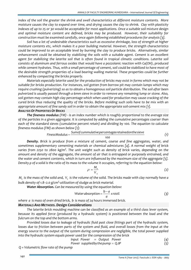
Figures 1a, 1b and 1c below show the compressed laterite soil brick molding machine. The machine working principle is based on the operation of a simple hydraulic system by using a hydraulic pump to controls two hydraulic cylinders. One of which conveys a downward force through the hydraulic arm to the press and produces compression force on the cement‐laterite‐water mix in the molding chamber. The other hydraulic cylinder is located at the base of the molding chamber. It is with the aid of this cylinder that the molded brick is ejected from the molding chamber by upward extension of the hydraulic arm through the molding chamber, thereby pushing the molded brick out of the chamber.
The machine performs these functions by the use of hydraulic units one which provides the upward compression and the other provides the downward compression and compaction for the two‐way compression and compaction molding process. The internal cavity of the molding chamber is usually lubricated before pouring the soil‐cement mix in order to ensure good surface finish of bricks and for easy ejection after molding. The following are the steps that should be followed in order to produce high quality bricks: (i) Set the bottom ram of the machine to the down position (ii) Open the top ram (iii) Use a mould releasing agent (oil) to lubricate the internal faces of the mould (iv) Fill the soil hopper with the mix up to its brim (v) Push the soil hopper across the face of the molding chamber and return it to its original position (vi) Close the top ram using the control valve (vii) Start the prime mover and use the control valve to move the bottom ram upward in order to
compact the soil‐cement mixture against the face of the top ram (viii) Also making use of the control valve, move the bottom ram upward in order to facilitate easy
ejection of the molded brick from the molding chamber. (ix) Carefully remove the ejected brick and place it on a wooden pallet prior to curing. (x) Return the bottom ram to its original down position in readiness for the next molding operation.
ANNALS OF FACULTY ENGINEERING HUNEDOARA – International Journal Of Engineering
© copyright FACULTY of ENGINEERING ‐ HUNEDOARA, ROMANIA 143
Figure 1a: Compressed laterite soil brick machine
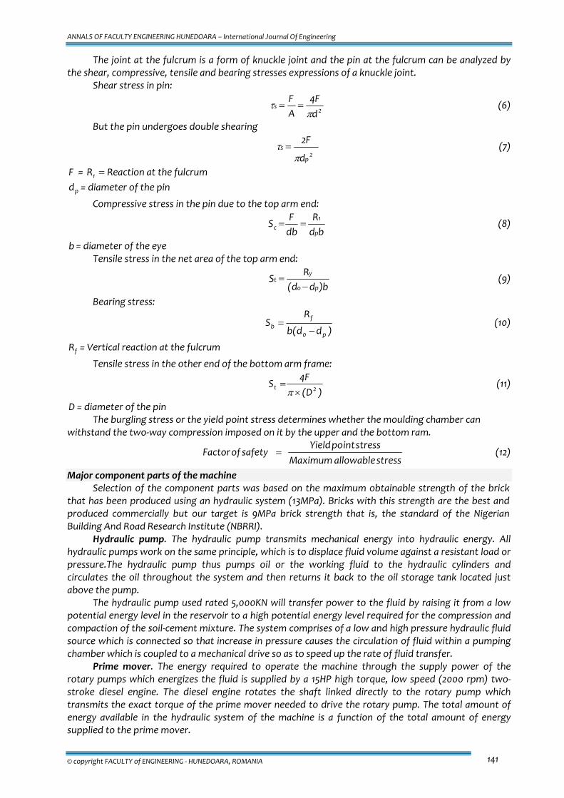
Figure 1b: Compression by lowering the top ram
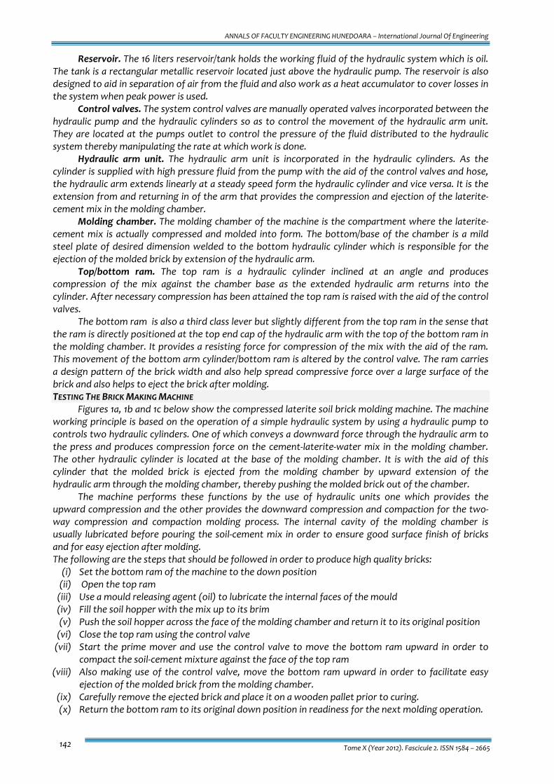
completely into the moulding chamber Figure 1c: Ejection of molded brick
Curing is a process of retaining moisture in bricks in order to improve the physiochemical reactions between the various components of the mixture thereby increasing the stability, strength and hardness of the brick. The period of curing usually takes up to three weeks depending on the type of soil and the stabilizer used. When bricks are collected from the moulding machine, they should be carefully placed on a non‐absorbing surface like plastic and covered with grass, leaves or tarpaulin in order to prevent the rapid evaporation of the bricks moisture. DISCUSSION OF RESULTS
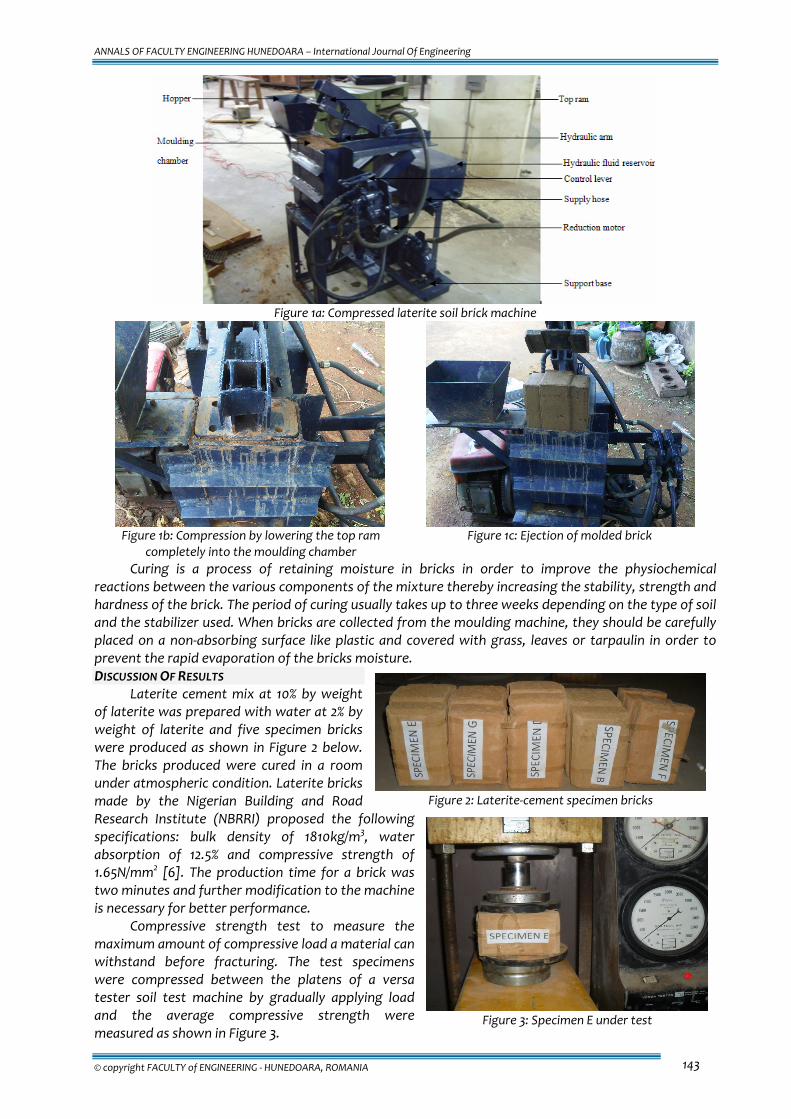
Laterite cement mix at 10% by weight of laterite was prepared with water at 2% by weight of laterite and five specimen bricks were produced as shown in Figure 2 below. The bricks produced were cured in a room under atmospheric condition. Laterite bricks made by the Nigerian Building and Road Research Institute (NBRRI) proposed the following specifications: bulk density of 1810kg/m3, water absorption of 12.5% and compressive strength of 1.65N/mm2 [6]. The production time for a brick was two minutes and further modification to the machine is necessary for better performance.
Compressive strength test to measure the maximum amount of compressive load a material can withstand before fracturing. The test specimens were compressed between the platens of a versa tester soil test machine by gradually applying load and the average compressive strength were measured as shown in Figure 3.
Figure 2: Laterite‐cement specimen bricks
Figure 3: Specimen E under test
ANNALS OF FACULTY ENGINEERING HUNEDOARA – International Journal Of Engineering
Tome X (Year 2012). Fascicule 2. ISSN 1584 – 2665 144
The results of the compressive strength test of the five specimens in table 1 which shows that these specimens did not really conform to the Nigerian Building and Road Research Institute standard and further work will be necessary to improve on the overall performance of the machine. CONCLUSIONS
A compressed laterite brick moulding machine was designed, fabricated and tested. The work was aimed at improving on the manual and semi‐manual ways of producing solid bricks by a simpler and highly efficient hydraulic system. The bricks produced are cheap, affordable and sourced from readily available laterite soil which is well suited to local weather conditions. The bricks produced are highly compressed and compacted by the application of compressive pressure in a two way compression of the soil‐cement mixture.
The machine was tested after fabrication and the performance of the machine was fairly satisfactory but the compressive test on the specimen bricks shows that the results did not really conform to the Nigerian Building and Road Research Institute standard and further work will be done to improve on the compressive ability and the overall performance of the machine. REFERENCES [1.] Onaolapo A.N. Modification and Testing of a Laterite‐cement Brick Moulding Machine. B.Eng Thesis,
Department of Mechanical Engineering, University of Ilorin, Ilorin, Nigeria, 2010 [2.] VSL REPORT SERIES. Properties of Masonry Design Considerations Post‐TensioningSystem for Masonry
Structures Applications, VSL International Ltd., Switzerland [3.] Charles W. Graham and Richard Burt. Soil Block Home Construction, BTEC Sustainable Buildings III Conference
Santa Fe, New Mexico, 2001 [4.] Hamish J.K. Gray. Establishing the Material Properties of Unreinforced Masonry Buildings in New Zealand,
Undergraduate Project, Department of Civil Engineering, University of Auckland, 2006 [5.] Herbert E. Merritt. Hydraulics Control System, John Wiley and Sons Inc. USA, 1967 [6.] Agbede I.O and Manasseh J, Use of cement‐sand admixture in laterite bricks production for low cost housing,
Leonardo electronic journal of practices and technologies 2008, P.163‐174
ANNALS OF FACULTY ENGINEERING HUNEDOARA
– INTERNATIONAL JOURNAL OF ENGINEERING
copyright © UNIVERSITY POLITEHNICA TIMISOARA, FACULTY OF ENGINEERING HUNEDOARA, 5, REVOLUTIEI, 331128, HUNEDOARA, ROMANIA
http://annals.fih.upt.ro
Table 1: Compressive strength of laterite‐cement bricks
Specimen Maximum load at failure (KN)
Compressive strength (N/mm2)
E 22.92 0.57 G 19.13 0.48 D 14.23 0.36 B 1246 0.32 F 11.12 0.28