Embed Size (px)
Citation preview
Design and Control of Growth Adaptable Artificial
Gravity Space Habitats
Raman Goyal∗, Tyler Bryant∗, Manoranjan Majji†, Robert E. Skelton‡
Department of Aerospace Engineering, Texas A&M University, TX, USA
Anthony Longman§
Skyframe Research & Development Inc., Camarillo, CA, USA
We seek to solve 5 unsolved problems in space: Providing gravity, food, radiationprotection, and a growable technology that enlarges the habitat as economics allow. Afull-scale center for space research is needed to keep the gravity gradient across the humanbody less than 6%, to avoid nausea and other health issues. The artificial gravity is providedby centripetal forces in a spinning habitat. The agricultural space occupies the low gravitypart of the habitat. The radiation protection requires 5m of regolith from ISRU. Thehabitat will be roomy and research can determine the level of gravity required for humanhealth, as ONLY a large space habitat can do (the plan grows to 225m radius yieldingonly 1% gravity gradient). The tensegrity paradigm is used for the design of the growthadaptable space structure. The mass required to sustain the centrifugal forces and theatmospheric pressure is minimized using the tensegrity structural paradigm. The transientdynamics of the structure during pressurization is shown. The growth strategy is plannedfor continuous occupancy of humans and agriculture. A control scheme is provided tostabilize the sun-pointing attitude, while spinning at a desired rate for artificial gravity.Numerical simulations are used to demonstrate the efficacy of the control laws for the spacehabitat system.
Nomenclature
N Node MatrixW External force MatrixCs Connectivity Matrixγ Force density in the string, N/mS String vectors Matrixρ Density, kg/m3
σ Yield strength, N/m2
Θ Direction Cosine Matrixω Desired Angular Velocity Vectorω Actual Angular Velocity Vectoreω Error in Angular VelocityJ Moment of Inertia, kg-m2
T Torque, N-mΩ2 Angular velocity to get required gravity at the surface, rad/secΩ3 Angular velocity (360 degrees/year) to follow the sun, rad/sec
Subscript
∗Graduate Student, Department of Aerospace Engineering, Texas A&M University, and AIAA Student Member.†Assistant Professor, Department of Aerospace Engineering, Texas A&M University, and AIAA Senior Member.‡TEES Distinguished Research Professor, Department of Aerospace Engineering, Texas A&M University, and AIAA Emeritus
Member.§Chief Designer & CEO, Skyframe Research & Development Inc., Camarillo, CA, 2013 NIAC Fellow, AIAA Associate.
1 of 15
American Institute of Aeronautics and Astronautics
Dow
nloa
ded
by 2
4.12
7.10
2.16
3 on
Oct
ober
7, 2
017
| http
://ar
c.ai
aa.o
rg |
DO
I: 1
0.25
14/6
.201
7-51
41
AIAA SPACE and Astronautics Forum and Exposition
12 - 14 Sep 2017, Orlando, FL
AIAA 2017-5141
Copyright © 2017 by the American Institute of Aeronautics and Astronautics, Inc.
All rights reserved.
AIAA SPACE Forum

i Variable number
I. Introduction
The USA has been in space for over 50 years in zero-g, and it is unhealthy. This project shows thefeasibility of artificial gravity (AG) in space while providing habitat growth adaptability, radiation protection,and agricultural space. There have been numerous studies showing the detrimental effects on the health ofastronauts due to the absence of gravitational field in space. Problems like bone density loss, impaired vision,muscle atrophy, cardiovascular deconditioning and immune system change are prevalent in astronauts afterspending considerable time in space.1–4 Various researchers have proposed AG in space for human spaceexploration.5–7 Projects like TransHab8 were started by NASA to provide earth like gravitational pull forlong journeys in space, but economics was a big deterrent and the problem still remains unsolved. We believethat a settlement in space, with research capabilities, is the most efficient path to solve the problems of longterm presence of humans in space, including space travel. We need to know what level of gravity is requiredfor human health, and we need to know that before launching long term space travel to Mars and further.We want an environment that allows children to grow normally.
Material resources are costly in space, so we must prove minimal mass concepts for our habitat structure.Tensegrity systems have been shown to produce minimal mass solutions to the five fundamental problemsin engineering mechanics: What is the minimal mass structure in the presence of i) torsional loads, ii)simply-supported bending loads, iii) compressive loads, iv) cantilevered loads, and iv) tension loads. Tensegrityis a network of axially loaded prestressable members. This definition is given by Skelton,9 but Fuller coinedthe word “Tensegrity” just to describe the work of Kenneth Snelson, namely a continuous network of tensionmembers separated by a discontinuous network of compressive members,.10,11 To differentiate betweenvarious types of tensegrity structures, Skelton defines a tensegrity configuration that has no contacts betweenits rigid bodies is a class 1 tensegrity system, and a tensegrity system with as many as k rigid bodiesin contact is a class k tensegrity system.9 The minimum mass solution for five fundamental engineeringmechanics problem has been provided by tensegrity systems.9,12–14 Furthermore, with tensegrity one canchange the shape of structures without changing stiffness, and can change stiffness without changing shape.Tensegrity offers the space industry easy controllability and deployability.15–19
The goal of this project is to provide artificial gravity and growth strategy to a large spacious habitat asopposed to current limited space cubicles. Several design concepts can be analyzed to provide enough spacefor humans and to maintain a constant gravity throughout the surface of the habitat. Section (II) discussesseveral possible habitat configurations such as the bola, spiral, torus, and cylinder. Concentric cylinderswere chosen as the design concept because of its easy fabrication, efficient use of space, and simple growthstrategy. In section (III), we discuss the growth strategy by adding more concentric cylinders and expandingthe shield to accommodate both people and agriculture life while maintaining a safe environment.
Section (IV) discusses the structural design of the cylinder membrane to optimize mass and provide therequired stiffness. The dynamics of the structure are shown during inflation and sudden pressure changetransients. Section (V) talks about the precession and attitude control of the habitat. Toward this end,we need to control the spin rate and direction of habitat to get enough sunlight and provide AG. We mustsatisfy three goals: spin the habitat to achieve 1g at the surface, spin the habitat about another axis to keepthe precession and always point toward the sun (the axis of rotation is pointing toward the sun). Finally,section (VI) provides the conclusion with the forward direction of some planned future work.
II. Design Concepts
The following design concepts were studied to meet the need of spacious environment, easy growth andconstant gravity.
A. Bola
A single cable could support a spacecraft on each end and spin at the correct rate to generate the requiredcentrifugal force. Then another Bola configuration could be added, with the spacecraft touching the previousones and connected to it with a door or larger opening. This process could continue until a complete torus is
2 of 15
American Institute of Aeronautics and Astronautics
Dow
nloa
ded
by 2
4.12
7.10
2.16
3 on
Oct
ober
7, 2
017
| http
://ar
c.ai
aa.o
rg |
DO
I: 1
0.25
14/6
.201
7-51
41
formed. However, small surface area to mass ratio is the biggest disadvantage of this design. Furthermore,this method of growth provides limited space for each module and the lack of variability of offering differentg levels in the habitat.
B. Spiral
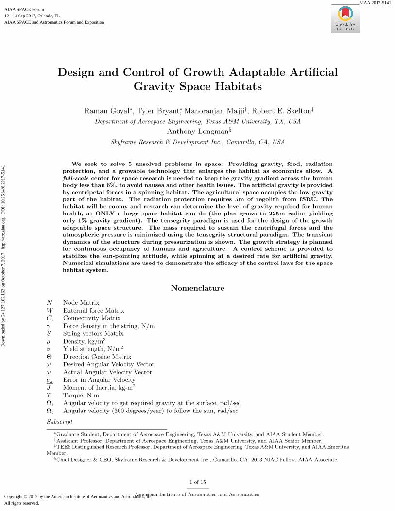
The idea of spiral structure seems very promising as it offers the easiest possible growth strategy. The growthstrategy would just add small increments at the end of the spiral structure. The problem with this notion ofgrowth is that center of mass (CM) of the whole structure changes with growth, so a constant gravity levelis not achieved at any local of the habitat. Research to find healthy gravitational levels would likely requireconstant acceleration levels for a specified period of time. Also a walk down the hall will change you gravitylevel even without the growth complications.
(a) Top view of the spiral (b) AG variation along spiral
Figure 1: Spiral Configuration
It can be observed from the above picture that CM is not at the origin of the spiral. Because of thisas people walk along the structure, the effective radius from the CM will change and thus the artificialgravity will also change. One way to solve this issue of moving CM is to add two spirals side by side, withboth incrementing in clockwise direction with 1800 phase apart. This will keep the CM at the origin. Theproblem with this approach is the changing radius in two spiral configurations will keep changing the CMof cylinders and will cause a wobbling motion about the CM of the whole structure. Hence we dismiss thespiral configuration.
C. Torus
The torus has been a very famous choice among all the ideas to provide artificial gravity in space. Thedrawbacks of this configuration are the complications of manufacturing, the difficult growth strategy, andthe wasted volume, compared to the concentric cylinders described next.
D. Cylinder
Rotating cylinders can be another option to create artificial gravity in space. This seems a very reasonablestructure to start with, as it is easy to build and can provide an easy growth strategy. Concentric cylinderscan be added without modifying the previous cylinders, except to add an end wall connecting the newcylinder. This method can also provide different g-values at different radii, including a zero-g workshopat the center of rotation (the original cylinder). The concentric circles at the edges of the cylinders allowsections to be joined giving the high stiffness. This adds greater stiffness without adding any mass, comparedto the spiral configurations discussed above. For these reasons, we choose the cylindrical approach over thespirals, even though the spirals simplify growth in the radial direction.
3 of 15
American Institute of Aeronautics and Astronautics
Dow
nloa
ded
by 2
4.12
7.10
2.16
3 on
Oct
ober
7, 2
017
| http
://ar
c.ai
aa.o
rg |
DO
I: 1
0.25
14/6
.201
7-51
41
III. Growth Strategy
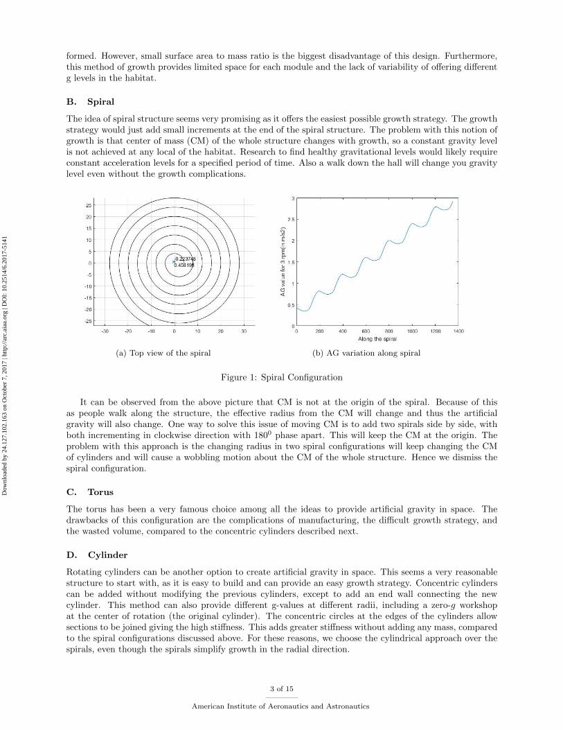
Figure 2 shows the conceptual view of the final space habitat. The blue color overlapping panels showthe shield structure required for protection from deep space radiation. Two large half circular plates inclinedto both sides of habitat represent the mirrors to provide sunlight into the habitat. The picture also shows atensegrity robot manufacturing a tensegrity structure for the infrastructure requirement.
Figure 2: Final conceptual view of Space Habitat with in-space robotic manufacturing
The growth strategy can be easily understood by looking at deployment stages shown in Figure 3-6. Figure3 shows the cross section view with blue panels around the habitat illustrating the shielding structure. Thearrows in the picture represent the sunlight which will bounce back from the shown mirror to provide sunlightinto the habitat. The picture also shows the photo-voltaic panels to generate electricity. Green interior partdepicts the pressurized environment for humans and agriculture while yellowish area is vacuum between thehabitat and the shield. The pink lines represent the cylindrical membrane or the pressure hull to hold thepressure inside. We also have provision for zero gravity workshops for conducting the required experimentsto better understand the space.
We start with a simple 40m× 40m (40m length, 40m diameter) circular cylinder. The next growth stepcan be to add another cylinder of larger radius. Figure 4a shows the assembly of new pressure hull membraneon the shield floor workbench. Tensegrity robots will be used for the laying out of the new floor. As theshield structure would be expanded new pressure hull floor will get stretched enabling lateral stiffness in themembrane. The first hull is already rotating at a certain angular speed to create AG at the surface. Now,the task is to get the new hull to desired radius and rotate it to match the angular speed of the previouscylinder. Powered bogies on the first hull will zero out the relative motion between the new and old hull. Apulling mechanism will set the new hull to its position and then will work as a Mitchell truss structure toprovide torsional stiffness in the structure as shown in figure 5a. The next step would be to cut tie-downcables between shield and the new hull. In addition to providing lateral tension in the hull, these cables willalso be helpful in controlled motion of the new hull to the prescribed location. In figure 6a, we see a bluepre-rolled window walls that will be unrolled down and zipped to floor to seal the pressurized environment.
4 of 15
American Institute of Aeronautics and Astronautics
Dow
nloa
ded
by 2
4.12
7.10
2.16
3 on
Oct
ober
7, 2
017
| http
://ar
c.ai
aa.o
rg |
DO
I: 1
0.25
14/6
.201
7-51
41
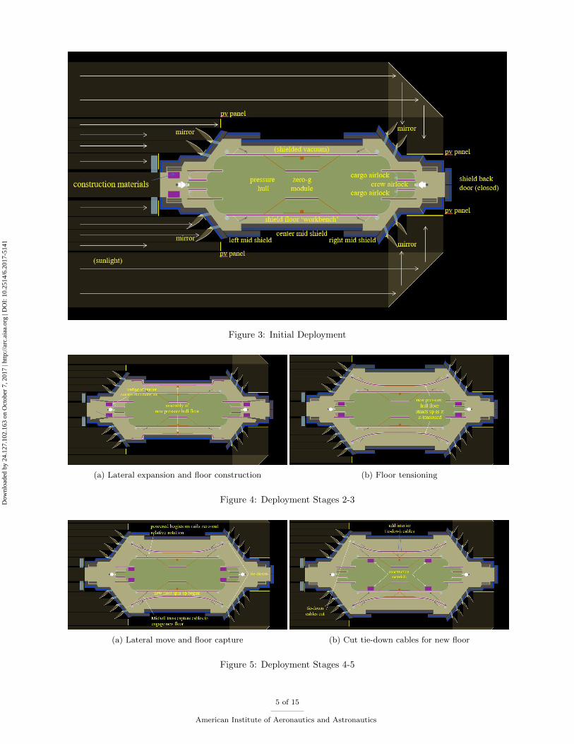
Figure 3: Initial Deployment
(a) Lateral expansion and floor construction (b) Floor tensioning
Figure 4: Deployment Stages 2-3
(a) Lateral move and floor capture (b) Cut tie-down cables for new floor
Figure 5: Deployment Stages 4-5
5 of 15
American Institute of Aeronautics and Astronautics
Dow
nloa
ded
by 2
4.12
7.10
2.16
3 on
Oct
ober
7, 2
017
| http
://ar
c.ai
aa.o
rg |
DO
I: 1
0.25
14/6
.201
7-51
41
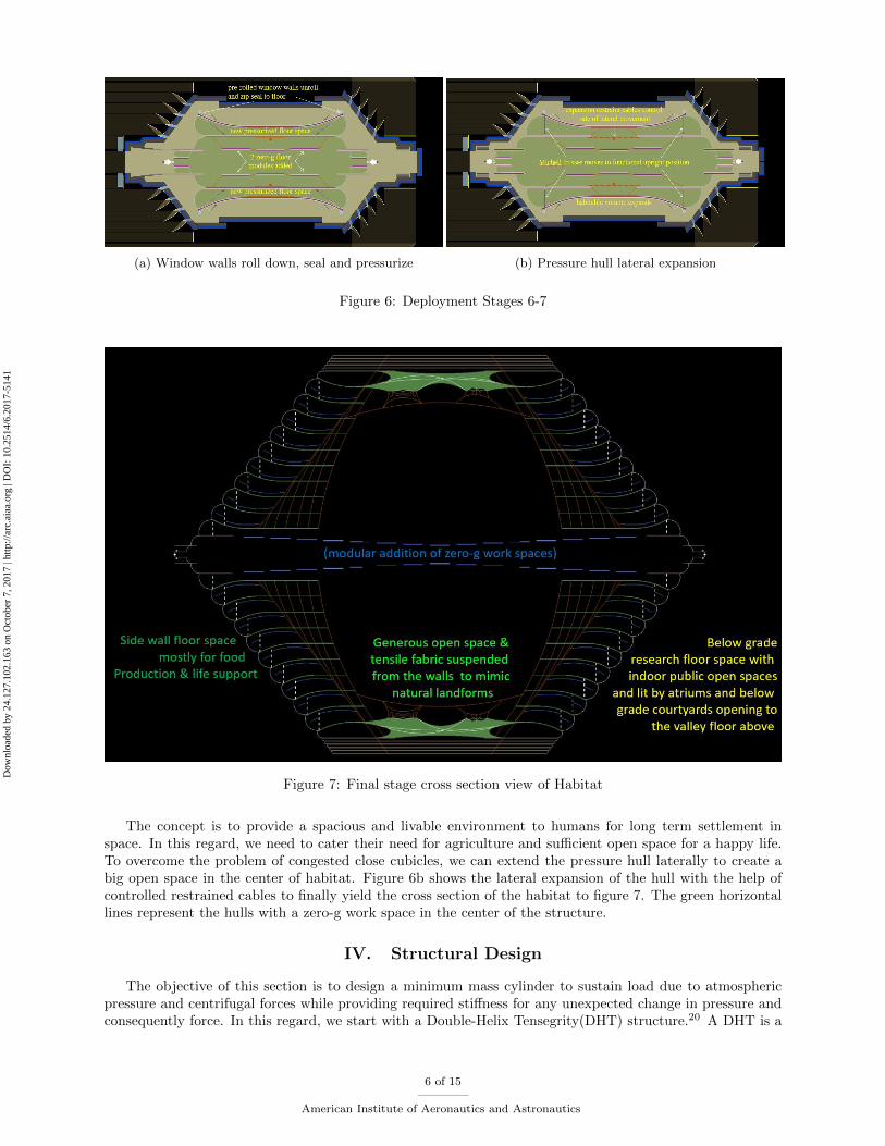
(a) Window walls roll down, seal and pressurize (b) Pressure hull lateral expansion
Figure 6: Deployment Stages 6-7
Figure 7: Final stage cross section view of Habitat
The concept is to provide a spacious and livable environment to humans for long term settlement inspace. In this regard, we need to cater their need for agriculture and sufficient open space for a happy life.To overcome the problem of congested close cubicles, we can extend the pressure hull laterally to create abig open space in the center of habitat. Figure 6b shows the lateral expansion of the hull with the help ofcontrolled restrained cables to finally yield the cross section of the habitat to figure 7. The green horizontallines represent the hulls with a zero-g work space in the center of the structure.
IV. Structural Design
The objective of this section is to design a minimum mass cylinder to sustain load due to atmosphericpressure and centrifugal forces while providing required stiffness for any unexpected change in pressure andconsequently force. In this regard, we start with a Double-Helix Tensegrity(DHT) structure.20 A DHT is a
6 of 15
American Institute of Aeronautics and Astronautics
Dow
nloa
ded
by 2
4.12
7.10
2.16
3 on
Oct
ober
7, 2
017
| http
://ar
c.ai
aa.o
rg |
DO
I: 1
0.25
14/6
.201
7-51
41

class-2 tensegrity structure with one set of bars following a clockwise pattern and another set of bars followingan anti-clockwise pattern. The static analysis shows no need of bars in the DHT cylinder as atmosphericpressure would be providing enough outward force or in other words, would be working as a compressivemember. Figure 8 shows the DHT pattern for certain complexity p and q where p is defined as the numberof nodes on circular ring and q is the number of circular rings in longitudinal direction, in which all the barshave been replaced by cables. This structure can provide radial and torsional stiffness to the structure dueto all the diagonal strings shown in the structure.
(a) Low complexity (b) High complexity
Figure 8: DHT structure with bars removed (R = 20m and L = 40m)
We need to optimize the complexity of the structure for minimum mass subject to yielding constraint,i.e. we need to find out the optimum number and configuration of the strings in this DHT pattern cylinderto take atmospheric pressure and centrifugal loads.
A. Minimum mass for cable network
Theorem IV.1. Minimum mass required by a tensegrity string structure to take certain given load andposition of nodes is constant, regardless of the configuration or number of strings, provided the configurationis in equilibrium.
Proof. We know the equilibrium equation for the string cable network for a structure is21
N(CTs γCs) = W
N(CTs γCs)NT = WNT
SγST = WNT . (1)
Now if we look at the minimum mass required for the structure,
m =ρ
σ[l21 l22 l23...]γ =
ρ
σ[ST1 S1 ST2 S2 ST3 S3...]γ
=ρ
σ
n∑i=1
STi Siγi =ρ
σ
n∑i=1
tr (SiSTi )γi
m =ρ
σtr (SγST ) =
ρ
σtr (WNT ). (2)
From the above mentioned theorem, it can be easily proven that minimum mass required by this cylinderdepends only on the external force matrix W and node position matrix N and does not depend on the
7 of 15
American Institute of Aeronautics and Astronautics
Dow
nloa
ded
by 2
4.12
7.10
2.16
3 on
Oct
ober
7, 2
017
| http
://ar
c.ai
aa.o
rg |
DO
I: 1
0.25
14/6
.201
7-51
41
configuration or the arrangement of the strings.
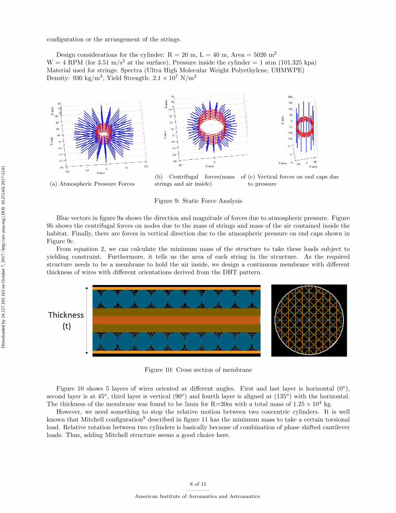
Design considerations for the cylinder: R = 20 m, L = 40 m, Area = 5026 m2
W = 4 RPM (for 3.51 m/s2 at the surface), Pressure inside the cylinder = 1 atm (101.325 kpa)Material used for strings: Spectra (Ultra High Molecular Weight Polyethylene, UHMWPE)Density: 930 kg/m3, Yield Strength: 2.1× 10⁷ N/m2
(a) Atmospheric Pressure Forces(b) Centrifugal forces(mass ofstrings and air inside)
(c) Vertical forces on end caps dueto pressure
Figure 9: Static Force Analysis
Blue vectors in figure 9a shows the direction and magnitude of forces due to atmospheric pressure. Figure9b shows the centrifugal forces on nodes due to the mass of strings and mass of the air contained inside thehabitat. Finally, there are forces in vertical direction due to the atmospheric pressure on end caps shown inFigure 9c.
From equation 2, we can calculate the minimum mass of the structure to take these loads subject toyielding constraint. Furthermore, it tells us the area of each string in the structure. As the requiredstructure needs to be a membrane to hold the air inside, we design a continuous membrane with differentthickness of wires with different orientations derived from the DHT pattern.
Figure 10: Cross section of membrane
Figure 10 shows 5 layers of wires oriented at different angles. First and last layer is horizontal (0o),second layer is at 45o, third layer is vertical (90o) and fourth layer is aligned at (135o) with the horizontal.The thickness of the membrane was found to be 5mm for R=20m with a total mass of 1.25× 10⁴ kg.
However, we need something to stop the relative motion between two concentric cylinders. It is wellknown that Mitchell configuration9 described in figure 11 has the minimum mass to take a certain torsionalload. Relative rotation between two cylinders is basically because of combination of phase shifted cantileverloads. Thus, adding Mitchell structure seems a good choice here.
8 of 15
American Institute of Aeronautics and Astronautics
Dow
nloa
ded
by 2
4.12
7.10
2.16
3 on
Oct
ober
7, 2
017
| http
://ar
c.ai
aa.o
rg |
DO
I: 1
0.25
14/6
.201
7-51
41
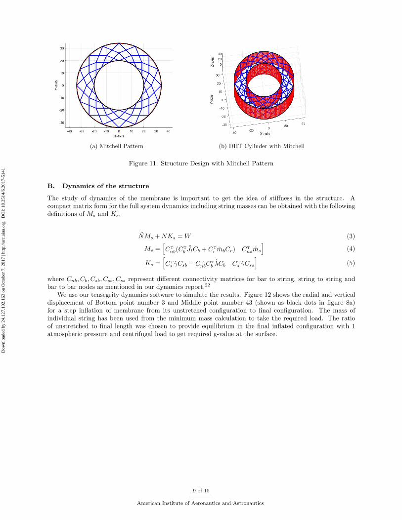
(a) Mitchell Pattern (b) DHT Cylinder with Mitchell
Figure 11: Structure Design with Mitchell Pattern
B. Dynamics of the structure
The study of dynamics of the membrane is important to get the idea of stiffness in the structure. Acompact matrix form for the full system dynamics including string masses can be obtained with the followingdefinitions of Ms and Ks.
NMs +NKs = W (3)
Ms =[CT
nb(CT
b JtCb + CTr mbCr) CT
nsms
](4)
Ks =[CTs γCsb − CT
nbCT
b λCb CTs γCss
](5)
where Cnb, Cb, Csb, Csb, Css represent different connectivity matrices for bar to string, string to string andbar to bar nodes as mentioned in our dynamics report.22
We use our tensegrity dynamics software to simulate the results. Figure 12 shows the radial and verticaldisplacement of Bottom point number 3 and Middle point number 43 (shown as black dots in figure 8a)for a step inflation of membrane from its unstretched configuration to final configuration. The mass ofindividual string has been used from the minimum mass calculation to take the required load. The ratioof unstretched to final length was chosen to provide equilibrium in the final inflated configuration with 1atmospheric pressure and centrifugal load to get required g-value at the surface.
9 of 15
American Institute of Aeronautics and Astronautics
Dow
nloa
ded
by 2
4.12
7.10
2.16
3 on
Oct
ober
7, 2
017
| http
://ar
c.ai
aa.o
rg |
DO
I: 1
0.25
14/6
.201
7-51
41

Figure 12: Time history of motion of the certain nodes (R = 20m and L = 40m) for Step Inflation
For the next simulation, we start from the equilibrium position of the structure with 1 atmosphericpressure difference from inside to outside of the cylinder. The stiffness of the individual string is based onthe minimum mass calculation. Damping is also added in the strings to get the η (Damping Coefficient)value of 0.1. Figure 13 shows the radial and longitudinal motion of the same nodes of the membrane inpresence of 10% instantaneous change in pressure.
Figure 13: Time history of motion of the certain nodes (R = 20m and L = 40m) for sudden pressure change
The above plot shows less than 4cm change in radial deformation in presence of 10% change in pressure
10 of 15
American Institute of Aeronautics and Astronautics
Dow
nloa
ded
by 2
4.12
7.10
2.16
3 on
Oct
ober
7, 2
017
| http
://ar
c.ai
aa.o
rg |
DO
I: 1
0.25
14/6
.201
7-51
41
i.e. 0.2% change in dimension which is acceptable in presence of such an unlikely event.
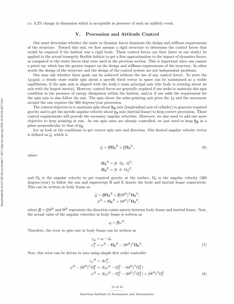
V. Precession and Attitude Control
One must determine whether the static or dynamic forces dominate the design and stiffness requirementsof the structure. Toward this end, we first assume a rigid structure to determine the control forces thatwould be required if the habitat was a rigid body. These control forces can then (later in our study) beapplied to the actual tensegrity flexible habitat to get a first approximation to the impact of dynamics forces,as compared to the static forces that were used in the previous section. This is important since one cannota priori say which has the greater impact on the design and stiffness requirements of the structure. In otherwords the design of the structure and the design of the control system are not independent problems.
One may ask whether these goals can be achieved without the use of any control forces. To meet the1g-goal, a steady state stable spin about a specific fixed vector in space can be maintained as a stableequilibrium, if the spin axis is aligned with the body’s main principal axis (the body is rotating about anaxis with the largest inertia). However, control forces are generally required if one seeks to maintain this spincondition in the presence of energy dissipation within the habitat, and/or if one adds the requirement forthe spin axis to also follow the sun. The spin about the solar-pointing axis gives the 1g and the movementaround the sun requires the 360 degrees/year precession.
The control objective is to maintain spin about b2 axis (longitudinal axis of cylinder) to generate requiredgravity and to get the specific angular velocity about e3 axis (inertial frame) to keep correct precession. Thesecontrol requirements will provide the necessary angular velocities. Moreover, we also need to add one moreobjective to keep pointing at sun. As our spin rates are already controlled, we just need to keep b2 in aplane perpendicular to that of e3.
Let us look at the conditions to get correct spin rate and direction. Our desired angular velocity vectoris defined as ω, which is
ω = BΩ2B + EΩ3
E , (6)
where
Ω2B = [0 Ω2 0]T ,
Ω3E = [0 0 Ω3]T .
and Ω2 is the angular velocity to get required gravity at the surface, Ω3 is the angular velocity (360degrees/year) to follow the sun and superscript B and E denote the body and inertial frame respectively.This can be written in body frame as
ω = BΩ2B + B(ΘB)TΩ3
E ,
ωB = Ω2B + (ΘB)TΩ3
E ,
where B = EΘB and ΘB represents the direction cosine matrix between body frame and inertial frame. Now,the actual value of the angular velocities in body frame is written as
ω = BωB .
Therefore, the error in spin rate in body frame can be written as
eω = ω − ω,eBω = ωB −Ω2
B − (ΘB)TΩ3E . (7)
Now, this error can be driven to zero using simple first order controller
eωB = AeBω ,
ωB − (ΘB)TΩE3 = A(ωB − ΩB2 − (ΘB)TΩE3 )
ωB = A(ωB − ΩB2 − (ΘB)TΩE3 ) + (ΘB)TΩE3 (8)
11 of 15
American Institute of Aeronautics and Astronautics
Dow
nloa
ded
by 2
4.12
7.10
2.16
3 on
Oct
ober
7, 2
017
| http
://ar
c.ai
aa.o
rg |
DO
I: 1
0.25
14/6
.201
7-51
41

As mentioned earlier, we also need to keep the b2 axis perpendicular to e3 axis in order to keep pointing atthe sun. In other words, the objective is to drive the following error to zero.
eθ = b2.e3
= B[0 1 0]T .E [0 0 1]T
= Eθ[0 1 0]T .E [0 0 1]T
= θ32
= [0 0 1]TΘ[0 1 0]
= kΘj. (9)
Here, we use second order controller to drive this error to zero
eθ + αeθ + βeθ = 0
kΘB j + αkΘB j + βkΘB j = 0
k(ΘBωB + ΘB ˙ωB)j + αkΘB j + βkΘB j = 0 (ΘB = ΘBωB + ΘB ˙ωB)
kΘB ˙ωB j = −αkΘB j − βkΘB j − kΘBωB j
(−θ31ω3 + θ33ω1) = −αkΘB j − βkΘB j − kΘBωB j, (10)
which can be written in terms of ω as
[θ33 0 − θ31]ω = −αkΘB j − βkΘB j − kΘBωB j. (11)
Now, combining last two equations from above mentioned objectives, we get[I
[θ33 0 − θ31]
]ω =
[A(ωB − ΩB2 − (ΘB)TΩE3 ) + (ΘB)TΩE3−αkΘB j − βkΘB j − kΘBωB j
]. (12)
A. Rigid Body Rotation Motion
Angular momentum of a rigid body represented in the body frame is given by
h = BJBωB , (13)
where JB and ωB are the moment of inertia and angular velocity of the body, respectively, both represented inbody frame. One can obtain the required torque by taking the inertial derivative of the angular momentum:
BTB = BJBωB + BJBωB . (14)
Using (B = BωB), this can be written as
TB = ωBJBωB + JBωB . (15)
This is the control torque required to make rigid space habitat’s attitude error converge to zero.
B. Results
To simulate the results, we assume the rigid body to be a cylinder of radius (R = 20m) and length (L =40m). We choose the b2 axis of the body frame to be aligned with the longitudinal axis of cylinder ande3 axis of inertial frame to be perpendicular to the ecliptic plane. Initially, the body frame is aligned withthe inertial frame. We use spectra (ultra high molecular weight polyethylene, UHMWPE) as the structurematerial, which has a density of 930 kg/m3 and a yield strength equal to 2.1 × 10⁷N/m2. The minimummass to take these loads constraint to yielding failure is 1.25× 10⁴ kg.
R = 20m, L = 40m
M = 1.25× 10⁴Kg
J2 = MR2, J1 = J3 =1
2MR2 +
1
12ML2
12 of 15
American Institute of Aeronautics and Astronautics
Dow
nloa
ded
by 2
4.12
7.10
2.16
3 on
Oct
ober
7, 2
017
| http
://ar
c.ai
aa.o
rg |
DO
I: 1
0.25
14/6
.201
7-51
41

1. Simulation I
This simulation gives us the result with perfect initial conditions.Initial Condition:
Ω3 = π/(180× 24× 3600) = 2.02× 10⁻⁷ (rad/sec)
Ω2 =√g/r = 0.7004 (rad/sec)
ωB(0) = [0 Ω2 Ω3]T , ΘB(0) = I3
Control Parameters:
A = −ε I3 where ε = 1× 10⁻³
α = 2/5, β = 2/25
Figure 14: No Initial Error
2. Simulation II
In this simulation we start with a small error rate of 1o/day out of ecliptic plane.Initial Condition:-
ωB(0) = [Ω3 Ω2 Ω3]T , ΘB(0) = I3
Control Parameters:
A = −ε I3 where ε = 1× 10⁻³
α = 2/5, β = 2/25
13 of 15
American Institute of Aeronautics and Astronautics
Dow
nloa
ded
by 2
4.12
7.10
2.16
3 on
Oct
ober
7, 2
017
| http
://ar
c.ai
aa.o
rg |
DO
I: 1
0.25
14/6
.201
7-51
41
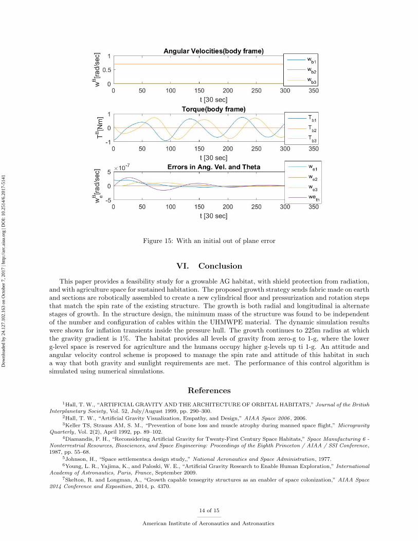
Figure 15: With an initial out of plane error
VI. Conclusion
This paper provides a feasibility study for a growable AG habitat, with shield protection from radiation,and with agriculture space for sustained habitation. The proposed growth strategy sends fabric made on earthand sections are robotically assembled to create a new cylindrical floor and pressurization and rotation stepsthat match the spin rate of the existing structure. The growth is both radial and longitudinal ia alternatestages of growth. In the structure design, the minimum mass of the structure was found to be independentof the number and configuration of cables within the UHMWPE material. The dynamic simulation resultswere shown for inflation transients inside the pressure hull. The growth continues to 225m radius at whichthe gravity gradient is 1%. The habitat provides all levels of gravity from zero-g to 1-g, where the lowerg-level space is reserved for agriculture and the humans occupy higher g-levels up ti 1-g. An attitude andangular velocity control scheme is proposed to manage the spin rate and attitude of this habitat in sucha way that both gravity and sunlight requirements are met. The performance of this control algorithm issimulated using numerical simulations.
References
1Hall, T. W., “ARTIFICIAL GRAVITY AND THE ARCHITECTURE OF ORBITAL HABITATS,” Journal of the BritishInterplanetary Society, Vol. 52, July/August 1999, pp. 290–300.
2Hall, T. W., “Artificial Gravity Visualization, Empathy, and Design,” AIAA Space 2006 , 2006.3Keller TS, Strauss AM, S. M., “Prevention of bone loss and muscle atrophy during manned space flight,” Microgravity
Quarterly, Vol. 2(2), April 1992, pp. 89–102.4Diamandis, P. H., “Reconsidering Artificial Gravity for Twenty-First Century Space Habitats,” Space Manufacturing 6 -
Nonterrestrial Resources, Biosciences, and Space Engineering: Proceedings of the Eighth Princeton / AIAA / SSI Conference,1987, pp. 55–68.
5Johnson, H., “Space settlements:a design study,,” National Aeronautics and Space Administration, 1977.6Young, L. R., Yajima, K., and Paloski, W. E., “Artificial Gravity Research to Enable Human Exploration,” International
Academy of Astronautics, Paris, France, September 2009.7Skelton, R. and Longman, A., “Growth capable tensegrity structures as an enabler of space colonization,” AIAA Space
2014 Conference and Exposition, 2014, p. 4370.
14 of 15
American Institute of Aeronautics and Astronautics
Dow
nloa
ded
by 2
4.12
7.10
2.16
3 on
Oct
ober
7, 2
017
| http
://ar
c.ai
aa.o
rg |
DO
I: 1
0.25
14/6
.201
7-51
41

8Kennedy, K., “Lessons from TransHab: An Architect’s Experience,” AIAA Space Architecture Symposium. Houston,Texas, 2002.
9Skelton, R. and de Oliveira, M., Tensegrity Systems, Springer US, 2009.10Fuller, R., Applewhite, E., and Loeb, A., Synergetics; explorations in the geometry of thinking, Macmillan, 1975.11Lalvani, H., “Origins Of Tensegrity: Views Of Emmerich, Fuller And Snelson,” International Journal of Space Structures,
Vol. 11, No. 1-2, 1996, pp. 27.12Skelton, R. E. and de Oliveira, M. C., “Optimal complexity of deployable compressive structures,” Journal of the Franklin
Institute, Vol. 347, No. 1, 2010, pp. 228–256.13Skelton, R. E. and de Oliveira, M. C., “Optimal tensegrity structures in bending: The discrete Michell truss,” Journal
of the Franklin Institute, Vol. 347, No. 1, 2010, pp. 257–283.14Skelton, R. E., Montuori, R., and Pecoraro, V., “Globally stable minimal mass compressive tensegrity structures,”
Composite Structures, Vol. 141, 2016, pp. 346–354.15Djouadi, S., Motro, R., Pons, J. C., and Crosnier, B., “Active Control of Tensegrity Systems,” Journal of Aerospace
Engineering, Vol. 11, No. 2, 1998, pp. 37–44.16Hagiwara, Y. and Oda, M., “Transformation experiment of a tensegrity structure using wires as actuators,” Mechatronics
and Automation (ICMA), 2010 International Conference on, 2010, pp. 985–990.17Koizumi, Y., Shibata, M., and Hirai, S., “Rolling tensegrity driven by pneumatic soft actuators,” Robotics and Automation
(ICRA), 2012 IEEE International Conference on, 2012, pp. 1988–1993.18Motro, R., “Structural morphology of tensegrity systems,” Meccanica, Vol. 46, No. 1, 2011, pp. 27–40.19Paul, C., Valero-Cuevas, F. J., and Lipson, H., “Design and control of tensegrity robots for locomotion,” IEEE
Transactions on Robotics, Vol. 22, No. 5, 2006, pp. 944–957.20Nagase, K. and Skelton, R. E., “Double-Helix Tensegrity Structures,” AIAA Journal , Vol. 53, No. 4, 2014, pp. 847–862.21Cheong, J. and Skelton, R. E., “Nonminimal Dynamics of General Class k Tensegrity Systems,” International Journal
of Structural Stability and Dynamics, Vol. 15, No. 2, 2015, pp. 1450042 (22 pages).22James V Henrickson, Raman Goyal, R. E. S., “Class K Tensegrity System Dynamics with Massive Strings and Elastic
Skin,” Texas A&M University, 2017.
15 of 15
American Institute of Aeronautics and Astronautics
Dow
nloa
ded
by 2
4.12
7.10
2.16
3 on
Oct
ober
7, 2
017
| http
://ar
c.ai
aa.o
rg |
DO
I: 1
0.25
14/6
.201
7-51
41