Embed Size (px)
Citation preview
Energy Research and Development Division
FINAL PROJECT REPORT
Demonstration of a Novel Ultra-Low Oxides of Nitrogen Boiler for Commercial Buildings
October 2021 | CEC-500-2021-045
PREPARED BY:
Primary Authors:
David Cygan
Sandeep Alavandi
Gas Technology Institute
1700 S. Mt. Prospect Road
Des Plaines, IL 60018
Phone: 847-768-0524 | Fax: 847-768-0501
http://www.gastechnology.org
Contract Number: PIR-14-004
PREPARED FOR:
California Energy Commission
Kevin Mori, P.E.
Project Manager
Virginia Lew
Office Manager
ENERGY EFFICIENCY RESEARCH OFFICE
Laurie ten Hope
Deputy Director
ENERGY RESEARCH AND DEVELOPMENT DIVISION
Drew Bohan
Executive Director
DISCLAIMER
This report was prepared as the result of work sponsored by the California Energy Commission. It does not necessarily
represent the views of the Energy Commission, its employees or the State of California. The Energy Commission, the
State of California, its employees, contractors and subcontractors make no warranty, express or implied, and assume
no legal liability for the information in this report; nor does any party represent that the uses of this information will
not infringe upon privately owned rights. This report has not been approved or disapproved by the California Energy
Commission nor has the California Energy Commission passed upon the accuracy or adequacy of the information in
this report.
i
ACKNOWLEDGEMENTS This report was submitted under Contract Number: PIR-14-004 from the California Energy
Commission. Thanks to Southern California Gas Company, Power Flame, Inc., Tetra Tech, Inc.
and host site Mission Linen Supply for financial, engineering, and technical support of this
project.
ii
PREFACE
The California Energy Commission’s (CEC) Energy Research and Development Division
manages the Natural Gas Research and Development Program, which supports energy-related
research, development, and demonstration not adequately provided by competitive and
regulated markets. These natural gas research investments spur innovation in energy
efficiency, renewable energy and advanced clean generation, energy-related environmental
protection, energy transmission and distribution and transportation.
The Energy Research and Development Division conducts this public interest natural gas-
related energy research by partnering with research, development, and demonstration entities,
including individuals, businesses, utilities and public and private research institutions. This
program promotes greater natural gas reliability, lower costs and increases safety for
Californians and is focused in these areas:
• Buildings End-Use Energy Efficiency.
• Industrial, Agriculture and Water Efficiency.
• Renewable Energy and Advanced Generation.
• Natural Gas Infrastructure Safety and Integrity.
• Energy-Related Environmental Research.
• Natural Gas-Related Transportation.
Demonstration of a Novel Ultra-Low Oxides of Nitrogen Boiler for Commercial Buildings is the
final report for the Demonstration of a Novel Ultra-Low Oxides of Nitrogen Boiler for
Commercial Buildings project (Contract Number: PIR-14-004) conducted by the Gas
Technology Institute. The information from this project contributes to Energy Research and
Development Division’s Natural Gas Research and Development Program.
For more information about the Energy Research and Development Division, please visit the
CEC’s research website (www.energy.ca.gov/research/) or contact the CEC at
iii
ABSTRACT The Gas Technology Institute, along with Power Flame, Inc.; Tetra Tech, Inc.; Southern
California Gas Company; and Mission Linen Supply, demonstrated an emerging efficient low
oxides of nitrogen burner technology, termed dynamic staged entrainment. The burner
incorporates dynamic flow geometry that induces entrainment of cooled products of
combustion to provide greater spatial uniformity in the distribution of the reacting species,
heat release rates, and temperatures. In addition, the technology allows for staging of
combustion reactants within the combustion chamber, providing further thermal distribution
within the chamber. These features minimize localized high-temperature regions within the
flame thereby limiting production of thermal oxides of nitrogen.
The project team installed the dynamic staged entrainment burner demonstration with a
commercial fire tube boiler at Mission Linen Supply in Santa Barbara, California. The
technology offers a simple design well-suited for application to commercial water
heating/steam generation. The burner consistently achieved emissions below 9 volumetric
parts per million oxides of nitrogen (NOx) without the need for costly and complex selective
catalytic reduction applied downstream of the boiler to remove NOx from the exhaust stream.
The technology also offers advantages over other alternatives for NOx reduction including
external flue gas recirculation, whereby exhaust products from the boiler stack are returned to
the burner inlet or burner operation at high excess air levels. Compared to flue gas
recirculation systems, the dynamic staged entrainment burner achieves similar or improved
efficiency, with further reductions in air blower power. In comparison to high excess air
burners, the dynamic staged entrainment burner is 2 percent more efficient and requires
significantly less electric power to drive the combustion air blower. The dynamic staged
entrainment technology offers a cost-competitive alternative to currently available equipment
for the commercial hot water/steam generation market in California in an easy-to-operate and
simple design.
Extensive evaluation of the technology for more than 10,000 hours of real-world conditions
have proven this burner is capable of meeting low NOx levels while operating with relatively
low excess air and high efficiency levels. The demonstration documented 9 percent savings in
fuel usage compared to the baseline conventional boiler. This result highlights the benefits of
applying a newer reliable boiler/burner technology, which can provide significant energy and
cost savings to commercial buildings.
Keywords: High-efficiency, low-emission, commercial buildings, boiler, firetube, steam, NOx
Please use the following citation for this report:
Cygan, David, and Sandeep Alavandi. Gas Technology Institute. 2021. Demonstration of a Novel Ultra-Low-Oxides of Nitrogen Boiler for Commercial Buildings. California Energy
Commission. Publication Number: CEC-500-2021-045.

iv
v
TABLE OF CONTENTS Page
ACKNOWLEDGEMENTS ...................................................................................................... i
PREFACE .......................................................................................................................... ii
ABSTRACT ....................................................................................................................... iii
EXECUTIVE SUMMARY ...................................................................................................... 1
CHAPTER 1: Technical Merit and Need ............................................................................... 5
Importance and Barriers ................................................................................................. 5
CHAPTER 2: Burner Development Considerations ................................................................ 7
Performance Targets ...................................................................................................... 7
Burner Design Concept ................................................................................................... 7
Burner Capacity and Geometric Constraints ...................................................................... 8
CHAPTER 3: Development Approach ................................................................................ 12
Computational Modelling Approach ................................................................................ 12
Experimental Testing Approach ..................................................................................... 14
Commercialization Approach ......................................................................................... 14
CHAPTER 4: Results and Discussion ................................................................................. 16
Computational Model Results ........................................................................................ 16
Experimental Test Results ............................................................................................. 18
CHAPTER 5: Benefits of the Technology ........................................................................... 28
Benefits in Comparison to Selective Catalytic Reduction Technologies ............................... 29
Benefits in Comparison to External Flue Gas Recirculation Technologies ........................... 30
Benefits in Comparison to High Excess Air Burner Technologies ....................................... 32
CHAPTER 6: Commercialization Status .............................................................................. 35
Field Demonstration ..................................................................................................... 35
Commissioning .......................................................................................................... 35
Operational Readiness ............................................................................................... 36
Controls ................................................................................................................... 36
Blower Operation ...................................................................................................... 37
Burner Operation ...................................................................................................... 38
Source Testing .......................................................................................................... 38
Continuous Operation ................................................................................................ 39
Manufacturing Partner .................................................................................................. 41
CHAPTER 7: Conclusions ................................................................................................. 43
vi
LIST OF ACRONYMS ....................................................................................................... 46
REFERENCES .................................................................................................................. 47
LIST OF FIGURES
Page
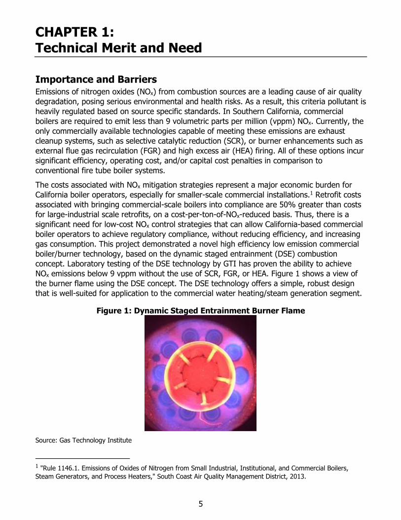
Figure 1: Dynamic Staged Entrainment Burner Flame .......................................................... 5
Figure 2: Schematic of Dynamic Staged Entrainment Burner Highlighting Key Design Features 8
Figure 3: Preliminary Computational Fluid Dynamics Results of the Recirculation Sleeve
Temperatures (degrees Kelvin) ........................................................................................ 12
Figure 4: Preliminary Computational Fluid Dynamics Results of the Combustion Zone
Temperatures (degrees Kelvin) ........................................................................................ 12
Figure 5: Preliminary Computational Fluid Dynamics Results of the Velocity Profiles through the
Burner Cross-Section (meters per second [m/s]) ............................................................... 13
Figure 6: Preliminary Computational Fluid Dynamics Results of the Velocity Profiles through the
Nozzle Centerline (m/s) ................................................................................................... 13
Figure 7: Prototype Dynamic Staged Entrainment Burner Installed on Gas Technology Inc.’s
Boiler Simulator Facility ................................................................................................... 14
Figure 8: Carbon Monoxide Concentration Profiles through the Flame Zone ......................... 16
Figure 9: Sleeve Temperature Results .............................................................................. 17
Figure 10: Oxides of Nitrogen Emissions Results ................................................................ 18
Figure 11: Computational Fluid Dynamics Model Predictions of Oxides of Nitrogen Emissions
for Varying Geometries ................................................................................................... 18
Figure 12: Flame Characteristics of the Dynamic Staged Entrainment Burner Design ............ 19
Figure 13: Performance Evaluation and Validation at Gas Technology Institute .................... 20
Figure 14: Grid Independence Study to Evaluate Mesh and its Impact on the Simulation
Results .......................................................................................................................... 21
Figure 15: Two Different Turbulence-Chemistry Interaction Models to Evaluate Model
Validation ....................................................................................................................... 22
Figure 16: Two Different Turbulence-Chemistry Interaction Models to Evaluate Model
Validation ....................................................................................................................... 23
Figure 17: Two Different Reaction Mechanisms to Evaluate Burner Simulation Results .......... 23
Figure 18: Two Different Reaction Mechanisms to Evaluate Burner Simulation Results .......... 24
Figure 19: Burner Hardware Temperature Compared to Experimental Data for Varying Excess
Air 25
vii
Figure 20: Comparison of Oxides of Nitrogen Emissions with Experimental Results for Excess
Air Factors ..................................................................................................................... 25
Figure 21: Carbon Monoxide Emissions Profile along Burner Length in Comparison to
Experimental Results ....................................................................................................... 26
Figure 22: Oxides of Nitrogen Emissions as a Function of Firing Rate .................................. 26
Figure 23: Comparison of Baseline and Design Data to Experimental Data ........................... 27
Figure 24: Exhaust Oxides of Nitrogen Emission Level versus Achievable Efficiency for the
Dynamic Staged Entrainment Burner ................................................................................ 28
Figure 25: Selective Catalytic Reduction System Integrated with a Conventional Boiler ......... 29
Figure 26: Integrated Boiler-Burner System Utilizing External Flue Gas Recirculation ............ 30
Figure 27: Impact of Excess Air Level on Boiler Efficiency................................................... 32
Figure 28: Complete Boiler/Burner System Shipped to Host Site ......................................... 35
Figure 29: Installation Sequence at Host Site .................................................................... 36
Figure 30: Boiler/Burner System Complete Installation at Host Site ..................................... 36
Figure 31: Honeywell Slate Controls with various Modules at the Bottom ............................. 37
Figure 32: Measurement Locations to ensure Consistent Operation ..................................... 37
Figure 33: Oxides of Nitrogen Emissions as a Function of Firing Rate Showing <9 vppm @3%
O2 38
Figure 34: Data Showing One Day Operation of the Boiler/Burner with Cycling and Load
Following ....................................................................................................................... 40
Figure 35: Operation of the Boiler/Burner since Installation ................................................ 40
LIST OF TABLES Page
Table 1: Nominal Boiler Combustion Chamber Diameters for Varying Boiler Sizes by
Manufacturer .................................................................................................................... 9
Table 2: Hurst Boiler Combustion Chamber Dimensions ..................................................... 10
Table 3: Comparison of the DSE Burner to a Conventional FGR Burner, Operation at <9 vppm
NOx 31
Table 4: Comparison of Dynamic Staged Entrainment Burner to Conventional Low-Oxides of
Nitrogen Burner, Operation at <9 vppm NOx ..................................................................... 33
Table 5: Energy Cost and Emissions Benefits of Dynamic Staged Entrainment Burner in
Comparison to Conventional High Excess Air Burner .......................................................... 34
Table 6:. Source Test Results .......................................................................................... 39
viii
Table 7: Comparison of Natural Gas (Therms) Consumed for Baseline Boiler and Gas
Technology Institute Boiler/Burner System ....................................................................... 41
Table 8: DSE Burner Performance Characteristics for Varying NOx Emissions Targets ........... 44
Table 9: Dynamic Staged Entrainment Burner Performance in Comparison to Conventional
Technologies at <9 vppm Oxides of Nitrogen .................................................................... 45
1
EXECUTIVE SUMMARY
The dynamic staged entrainment burner developed by the Gas Technology Institute was
installed with a commercial fire tube boiler at Mission Linen Supply to provide steam for
commercial laundry use. The technology design specifically addresses commercial heating
applications to achieve compliance with stringent oxides of nitrogen (NOx) regulations while
improving efficiency. Deployment of the technology could reduce the demand for natural gas
at many different commercial sites, and consequently the overall natural gas demand in
California. Natural gas ratepayers will benefit from increased efficiency of natural gas-fired
equipment, more efficient use of gas, and reduced gas use for heating and hot water.
Commercial facilities will benefit from energy efficiency and environmental stewardship,
sustainable energy use, good citizenship, lower natural gas costs, and increased profits. Given
the alignment of the project with Public Interest Energy Research program goals, grant
funding was a suitable resource for furthering the advancement of the technology towards
market deployment. Benefits of this program accrue primarily to the California ratepayers in
the form of energy savings, reduced energy cost, reduced carbon dioxide (CO2) and NOx
emissions. While laboratory testing performed by the project team members has proven the
performance of the system, a high-visibility demonstration of the dynamic staged entrainment
technology at a California host site under real world conditions was necessary to transfer
knowledge of the technology to California markets.
The costs associated with NOx mitigation strategies represent a major economic burden for
California boiler operators, especially for smaller-scale commercial installations. Retrofit costs
associated with bringing commercial-scale boilers into compliance are 50 percent greater than
costs for large-industrial scale retrofits, on a cost-per-ton-of-NOx-reduced basis. Thus, there is
a significant need for low-cost NOx control strategies that can allow California-based
commercial boiler operations to achieve regulatory compliance, without reducing efficiency,
and increasing gas consumption. The only technologies which are currently commercially
available to achieve NOx emissions <9 volumetric parts per million (vppm) are selective
catalytic reduction, external flue gas recirculation, and high excess air burners. All of these
technologies incur penalties to operating efficiency and can add significantly to the cost of
operation. The selective catalytic reduction systems require substantial investment in ancillary
downstream equipment and qualified personnel for operation and maintenance. These factors
make selective catalytic reduction economically unviable for most commercial heating
distributions systems. Similarly, external flue gas recirculation systems require additional
equipment and controls, adding to capital costs, reducing overall system efficiency, and
making them unattractive for the commercial heating market. The high excess air burners
operate with substantially elevated air levels, resulting in significant losses to boiler efficiency
and hence, increased fuel consumption, operating costs, and greenhouse gas (GHG)
emissions. Moreover, the increased blower sizes required for the high excess air burners
further add to capital costs and electrical demands. Thus, dynamic staged entrainment
technology has the potential to emerge as a cost-effective, high efficiency alternative for the
commercial boiler market.
The scale of the demonstration system, although it is at an industrial site, is well positioned in
commercial building heating and hot water load range. This allows data from the
demonstration tests to be used with confidence across a broad range of commercial
applications. The team estimated that dynamic staged entrainment technology would be
2
capable of replacing 40,625 boiler horsepower (BHP worth) of California commercial boiler
capacity within 10 years of market commercialization. In comparison to competing high excess
air high excess air high excess air technologies which currently dominate the California
commercial market segment, this will provide an annual reduction of 119,600 million British
thermal units (MMBtu) and 928,850 kilowatt-hours (kWh) of natural gas and electricity
consumption, respectively. This equates to a combined savings of more than $930,000 in
annual energy costs for California commercial boiler operators. Annually, this will reduce
California CO2 and NOx emissions by 7,380 tons and 1,315 pounds, respectively. These
substantial benefits to California will continue to extend even further as dynamic staged
entrainment technology gains market share within the commercial building sector.
The dynamic staged entrainment burner technology developed within this project has satisfied
all performance targets set forth, demonstrating the ability to achieve <9 vppm NOx emissions.
The host site demonstration documented a 9 percent savings in fuel usage as compared to the
baseline conventional boiler. This highlights the benefits of applying a newer reliable
boiler/burner technology, which can provide significant energy and cost savings to commercial
buildings. Successful completion of this demonstration project has built confidence and
awareness of the dynamic staged entrainment technology, furthering commercialization
efforts, and ultimately helping to bring to market a cost-competitive, efficient alternative for
California commercial boiler operators seeking to reduce operating costs and greenhouse gas
emissions, while maintaining regulatory compliance.
Beyond this, the technology demonstrated a wide range of operational latitude, with the ability
to achieve NOx emissions from less than 20 vppm to less than 9 vppm, allowing the burner to
adapt to a broad set of markets with varying regulatory requirements. This operational
flexibility was achieved without need for modification to the burner equipment, allowing the
burner to be tuned for different applications with simple operating adjustments made during
commissioning.
Widespread deployment of the dynamic staged entrainment burner will provide several
environmental, performance and life cycle cost benefits to California ratepayers including:
• Reduced operating costs through reduced gas and electricity consumption resulting
from higher system efficiency in comparison to currently deployed technologies.
• Reduced CO2 and NOx emissions resulting from reduced energy consumption.
• Reduced equipment cost for commercial-scale NOx mitigation — the costs for the
technology are anticipated to be less than competing alternative control measures.
• Cost-effective path for air quality compliance in commercial boiler applications — the
capital and operating costs associated with currently available NOx mitigation strategies
represent a significant economic burden to California boiler operators, especially for
smaller commercial scale operations. The technology provides cost-effective solution for
NOx reduction, especially for the commercial building sector.
• Reliable operation and equipment longevity — the technology applies fundamental NOx
reduction strategies in a simple design without the complicating elements of selective
catalytic reduction or external flue gas recirculation; thus, system reliability and
longevity are expected to be high, with an anticipated equipment lifetime of more than
30 years.

3
To bring the technology to market, Gas Technology Institute has partnered with Power Flame
Inc., a leading manufacturer in the United States of burners for commercial and industrial
applications. Power Flame has been actively engaged in the burner development efforts to
date and continues to express great enthusiasm for the technology. Given the high
performance of the technology and the straightforward, low-cost design, the team is confident
they will be able to offer the product to market with competitive pricing, ultimately enabling
broad deployment.

4
5
CHAPTER 1: Technical Merit and Need
Importance and Barriers Emissions of nitrogen oxides (NOx) from combustion sources are a leading cause of air quality
degradation, posing serious environmental and health risks. As a result, this criteria pollutant is
heavily regulated based on source specific standards. In Southern California, commercial
boilers are required to emit less than 9 volumetric parts per million (vppm) NOx. Currently, the
only commercially available technologies capable of meeting these emissions are exhaust
cleanup systems, such as selective catalytic reduction (SCR), or burner enhancements such as
external flue gas recirculation (FGR) and high excess air (HEA) firing. All of these options incur
significant efficiency, operating cost, and/or capital cost penalties in comparison to
conventional fire tube boiler systems.
The costs associated with NOx mitigation strategies represent a major economic burden for
California boiler operators, especially for smaller-scale commercial installations.1 Retrofit costs
associated with bringing commercial-scale boilers into compliance are 50% greater than costs
for large-industrial scale retrofits, on a cost-per-ton-of-NOx-reduced basis. Thus, there is a
significant need for low-cost NOx control strategies that can allow California-based commercial
boiler operators to achieve regulatory compliance, without reducing efficiency, and increasing
gas consumption. This project demonstrated a novel high efficiency low emission commercial
boiler/burner technology, based on the dynamic staged entrainment (DSE) combustion
concept. Laboratory testing of the DSE technology by GTI has proven the ability to achieve
NOx emissions below 9 vppm without the use of SCR, FGR, or HEA. Figure 1 shows a view of
the burner flame using the DSE concept. The DSE technology offers a simple, robust design
that is well-suited for application to the commercial water heating/steam generation segment.
Figure 1: Dynamic Staged Entrainment Burner Flame
Source: Gas Technology Institute
1 "Rule 1146.1. Emissions of Oxides of Nitrogen from Small Industrial, Institutional, and Commercial Boilers,
Steam Generators, and Process Heaters," South Coast Air Quality Management District, 2013.
6
The DSE technology was developed by GTI in cooperation with Power Flame Inc., a major U.S.
burner manufacturer, for use in commercial boiler applications to meet the requirements of
commercial heating and hot water demands. The demonstration effort allowed the team to
effectively transition the technology towards a commercial product offering for the California
commercial building sector. Following successful demonstration and validation of the DSE
boiler system, the team is better positioned to deploy this breakthrough technology
throughout the California commercial boiler segment, ultimately reducing end-user costs and
energy consumption.
By operating without the use of SCR, FGR, or HEA, the DSE technology offers a new pathway
for commercial boiler operators to achieve regulatory compliance at a lower cost and with
higher energy efficiency than is possible with currently available NOx mitigation strategies.
Demonstration of the DSE technology strongly supports PIER program goals of “advanced
efficiency solutions, including technologies and approaches for more affordable and
comfortable buildings” and broader California statewide goals of “increased energy efficiency
in buildings.” This project aimed to provide an environmentally sound, safe, reliable, and
affordable energy product while satisfying the unique California requirement of smog
mitigation through NOx reduction. The DSE system increases the overall efficiency of natural
gas-fired equipment, while decreasing natural gas and electricity demand, with an associated
decrease in NOx and GHG emissions.
This project addressed key issues with current low NOx systems by demonstrating a cost
effective, high efficiency technology based on a unique, but proven concept at a host site
facility. The project advanced the scientific and economic understanding of the DSE
technology, while proving cost effectiveness, safety, and reliability, and widely transferring the
results to the California’s commercial sector.
7
CHAPTER 2: Burner Development Considerations
Performance Targets The objective was to develop a burner for commercial and industrial steam and hot water
boiler applications that achieves <9 vppm NOx without the need for SCR, FGR, or HEA
operation. To achieve broad market appeal, the burner must maintain adequate reliability,
turndown, and efficiency, and be capable of deployment in other boiler markets that have less
stringent NOx regulations. Additionally, the combustion air blower pressure and power
requirements must be satisfactory with respect to conventional blower equipment capabilities
and burner manufacturer expectations. The key performance targets are summarized as
follows:
1. <9 vppm NOx across full operational turndown
2. <400 vppm carbon monoxide (CO) across full operational turndown
3. 4:1 turndown in firing rate
4. SCR, FGR, and/or HEA not required for operation
5. Manufacturer-acceptable combustion air blower requirements
Burner Design Concept The dominant mode of NOx formation during natural gas combustion results from the reaction
of oxygen and nitrogen at high temperatures. Low NOx combustion strategies seek to mitigate
this “thermal” NOx formation by reducing peak temperatures within the flame. However, when
flame temperatures get too low, flame ignition and stability can become problematic, leading
to increased carbon monoxide (CO) and total unburned hydrocarbon (THC) emissions. The
envelope between achieving low NOx production and maintaining complete combustion
becomes narrower as the requirements for low NOx become more stringent. Achieving
satisfactory flame stability and turndown, while also maintaining NOx emissions below 9 vppm
was one of the main challenges addressed during the project.
To achieve the required performance targets, GTI developed an advanced burner concept as
shown in Figure 2, which maintains flame stability while reducing NOx levels. The DSE burner
technology employs four distinct NOx mitigation strategies, all of which serve to reduce peak
flame temperatures and inhibit thermal NOx formation.
1. Premixing of Fuel and Air — Natural gas and air are thoroughly mixed upstream of the
burner nozzles. This serves to ensure that the reactions taking place throughout the
flame zone occur at the desired combustion stoichiometry, and therefore at the desired
reaction temperatures.—2. Recirculation of Cooled Combustion Products – The dynamic
flow geometry of the burner promotes recirculation and entrainment of cooled
combustion products from the primary combustion zone. This serves to dilute the
combustion mixture in the same fashion as FGR, reducing peak flame temperatures and
NOx formation.
8
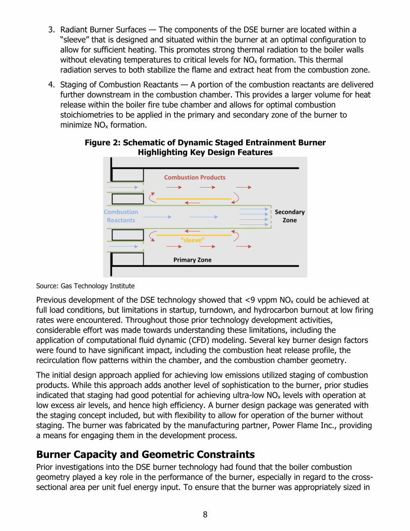
3. Radiant Burner Surfaces — The components of the DSE burner are located within a
“sleeve” that is designed and situated within the burner at an optimal configuration to
allow for sufficient heating. This promotes strong thermal radiation to the boiler walls
without elevating temperatures to critical levels for NOx formation. This thermal
radiation serves to both stabilize the flame and extract heat from the combustion zone.
4. Staging of Combustion Reactants — A portion of the combustion reactants are delivered
further downstream in the combustion chamber. This provides a larger volume for heat
release within the boiler fire tube chamber and allows for optimal combustion
stoichiometries to be applied in the primary and secondary zone of the burner to
minimize NOx formation.
Figure 2: Schematic of Dynamic Staged Entrainment Burner Highlighting Key Design Features
Source: Gas Technology Institute
Previous development of the DSE technology showed that <9 vppm NOx could be achieved at
full load conditions, but limitations in startup, turndown, and hydrocarbon burnout at low firing
rates were encountered. Throughout those prior technology development activities,
considerable effort was made towards understanding these limitations, including the
application of computational fluid dynamic (CFD) modeling. Several key burner design factors
were found to have significant impact, including the combustion heat release profile, the
recirculation flow patterns within the chamber, and the combustion chamber geometry.
The initial design approach applied for achieving low emissions utilized staging of combustion
products. While this approach adds another level of sophistication to the burner, prior studies
indicated that staging had good potential for achieving ultra-low NOx levels with operation at
low excess air levels, and hence high efficiency. A burner design package was generated with
the staging concept included, but with flexibility to allow for operation of the burner without
staging. The burner was fabricated by the manufacturing partner, Power Flame Inc., providing
a means for engaging them in the development process.
Burner Capacity and Geometric Constraints Prior investigations into the DSE burner technology had found that the boiler combustion
geometry played a key role in the performance of the burner, especially in regard to the cross-
sectional area per unit fuel energy input. To ensure that the burner was appropriately sized in
“sleeve”
Primary Zone
Combustion Reactants
Secondary Zone
Combustion Products
9
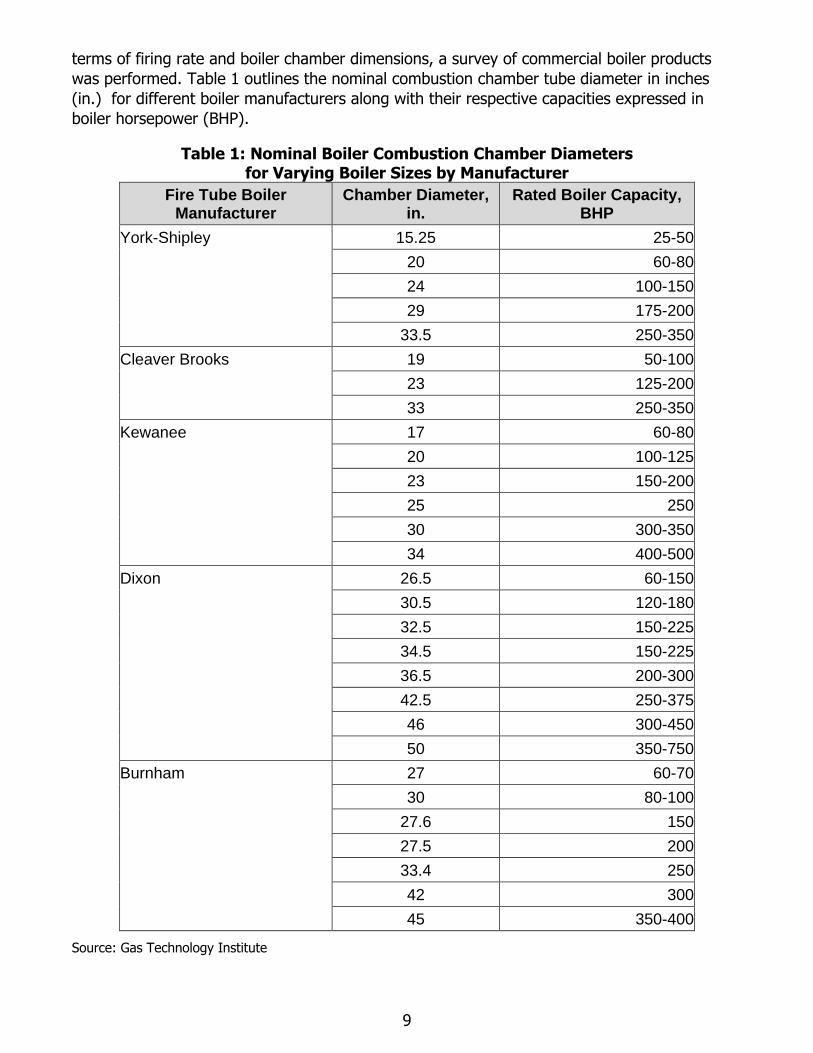
terms of firing rate and boiler chamber dimensions, a survey of commercial boiler products
was performed. Table 1 outlines the nominal combustion chamber tube diameter in inches
(in.) for different boiler manufacturers along with their respective capacities expressed in
boiler horsepower (BHP).
Table 1: Nominal Boiler Combustion Chamber Diameters for Varying Boiler Sizes by Manufacturer
Fire Tube Boiler Manufacturer
Chamber Diameter, in.
Rated Boiler Capacity, BHP
York-Shipley 15.25 25-50
20 60-80
24 100-150
29 175-200
33.5 250-350
Cleaver Brooks 19 50-100
23 125-200
33 250-350
Kewanee 17 60-80
20 100-125
23 150-200
25 250
30 300-350
34 400-500
Dixon 26.5 60-150
30.5 120-180
32.5 150-225
34.5 150-225
36.5 200-300
42.5 250-375
46 300-450
50 350-750
Burnham 27 60-70
30 80-100
27.6 150
27.5 200
33.4 250
42 300
45 350-400
Source: Gas Technology Institute
10
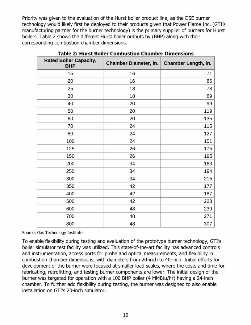
Priority was given to the evaluation of the Hurst boiler product line, as the DSE burner
technology would likely first be deployed to their products given that Power Flame Inc. (GTI’s
manufacturing partner for the burner technology) is the primary supplier of burners for Hurst
boilers. Table 2 shows the different Hurst boiler outputs by (BHP) along with their
corresponding combustion chamber dimensions.
Table 2: Hurst Boiler Combustion Chamber Dimensions
Rated Boiler Capacity, BHP
Chamber Diameter, in. Chamber Length, in.
15 16 71
20 16 86
25 18 78
30 18 89
40 20 99
50 20 119
60 20 135
70 24 115
80 24 127
100 24 151
125 26 175
150 26 195
200 34 163
250 34 194
300 34 215
350 42 177
400 42 187
500 42 223
600 48 239
700 48 271
800 48 307
Source: Gas Technology Institute
To enable flexibility during testing and evaluation of the prototype burner technology, GTI’s
boiler simulator test facility was utilized. This state-of-the-art facility has advanced controls
and instrumentation, access ports for probe and optical measurements, and flexibility in
combustion chamber dimensions, with diameters from 20-inch to 40-inch. Initial efforts for
development of the burner were focused at smaller load scales, where the costs and time for
fabricating, retrofitting, and testing burner components are lower. The initial design of the
burner was targeted for operation with a 100 BHP boiler (4 MMBtu/hr) having a 24-inch
chamber. To further add flexibility during testing, the burner was designed to also enable
installation on GTI’s 20-inch simulator.

11
Initial development was performed with full load testing at 4 MMBtu/hr. As the development
activities progressed, the project team was successful in securing funding from the California
Energy Commission and Southern California Gas Company to demonstrate the burner
technology at a customer facility under real-world conditions. Under this demonstration effort,
the host customer required full load steam generating capability at 125 BHP, such that the
burner must achieve the desired performance with firing rates up to 5.25 MMBtu/hr.
Therefore, the team selected a Hurst 125 BHP boiler.
12
CHAPTER 3: Development Approach
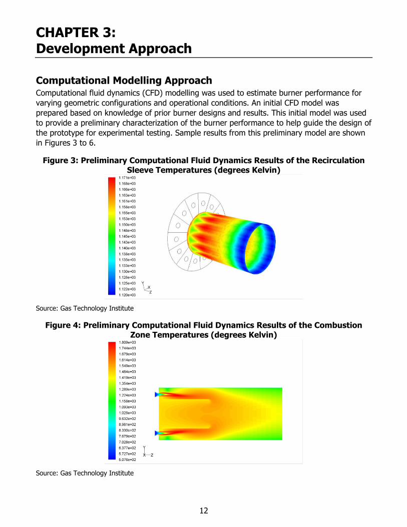
Computational Modelling Approach Computational fluid dynamics (CFD) modelling was used to estimate burner performance for
varying geometric configurations and operational conditions. An initial CFD model was
prepared based on knowledge of prior burner designs and results. This initial model was used
to provide a preliminary characterization of the burner performance to help guide the design of
the prototype for experimental testing. Sample results from this preliminary model are shown
in Figures 3 to 6.
Figure 3: Preliminary Computational Fluid Dynamics Results of the Recirculation Sleeve Temperatures (degrees Kelvin)
Source: Gas Technology Institute
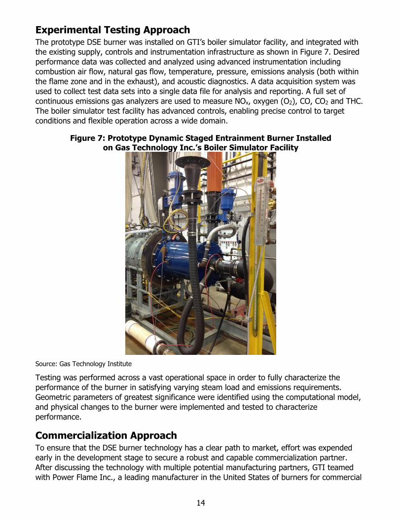
Figure 4: Preliminary Computational Fluid Dynamics Results of the Combustion Zone Temperatures (degrees Kelvin)
Source: Gas Technology Institute

13
Figure 5: Preliminary Computational Fluid Dynamics Results of the Velocity Profiles through the Burner Cross-Section (meters per second [m/s])
Source: Gas Technology Institute
Figure 6: Preliminary Computational Fluid Dynamics Results of the Velocity Profiles through the Nozzle Centerline (m/s)
Source: Gas Technology Institute
An initial prototype burner was designed and fabricated based on information from the
preliminary CFD model and results of GTI’s extensive development and experimental studies
throughout prior efforts. The prototype burner was then installed on GTI’s boiler simulator test
facility and initial experimental data was gathered. The preliminary CFD model was then
revised until it agreed with the initial experimental results. Once validated, the revised CFD
model was used to perform parametric studies of varying burner configurations and
operational characteristics. These computational modelling studies provided key insights into
the flame behavior and operational characteristics, serving as a powerful tool for guiding
design and development decisions. Moreover, these studies reduced the number of burner
geometric design parameters to be evaluated, focusing experimental studies on parameters of
greatest interest.
14
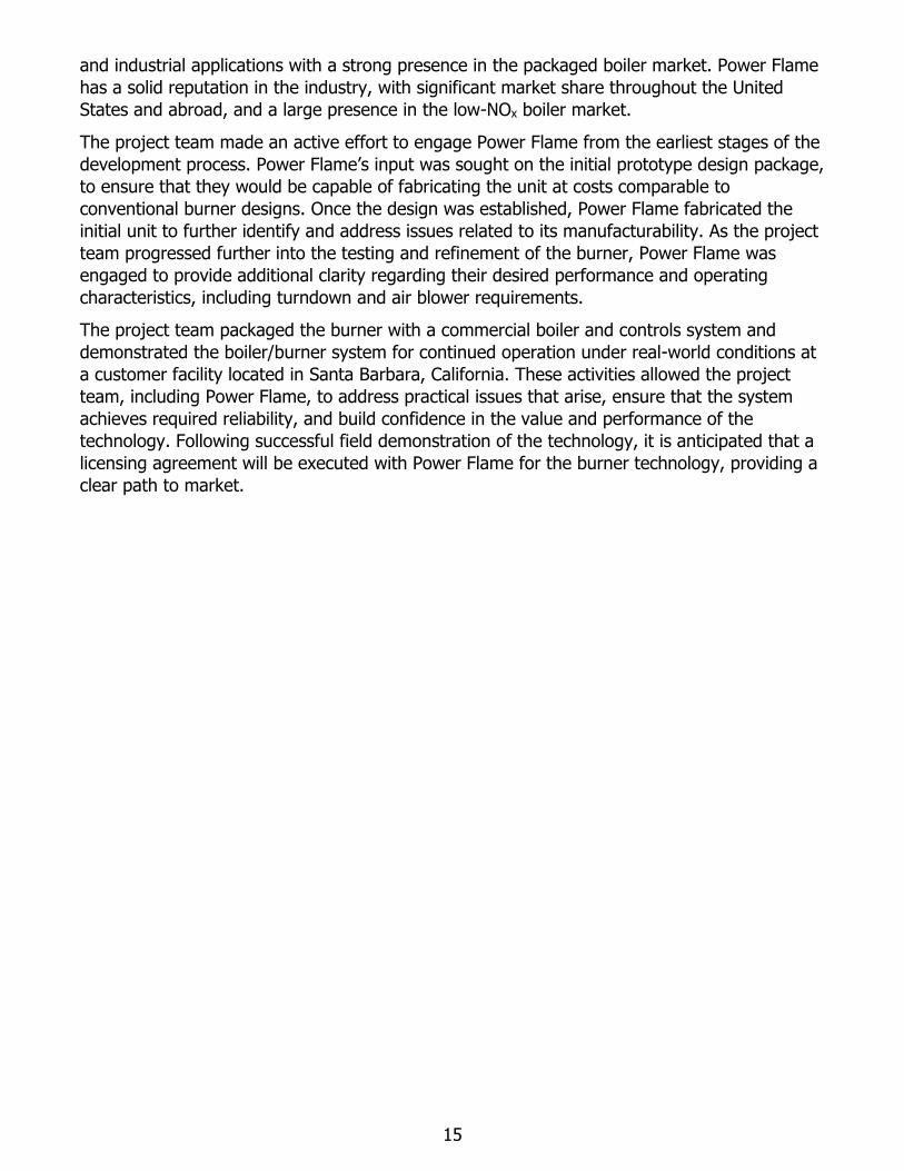
Experimental Testing Approach The prototype DSE burner was installed on GTI’s boiler simulator facility, and integrated with
the existing supply, controls and instrumentation infrastructure as shown in Figure 7. Desired
performance data was collected and analyzed using advanced instrumentation including
combustion air flow, natural gas flow, temperature, pressure, emissions analysis (both within
the flame zone and in the exhaust), and acoustic diagnostics. A data acquisition system was
used to collect test data sets into a single data file for analysis and reporting. A full set of
continuous emissions gas analyzers are used to measure NOx, oxygen (O2), CO, CO2 and THC.
The boiler simulator test facility has advanced controls, enabling precise control to target
conditions and flexible operation across a wide domain.
Figure 7: Prototype Dynamic Staged Entrainment Burner Installed on Gas Technology Inc.’s Boiler Simulator Facility
Source: Gas Technology Institute
Testing was performed across a vast operational space in order to fully characterize the
performance of the burner in satisfying varying steam load and emissions requirements.
Geometric parameters of greatest significance were identified using the computational model,
and physical changes to the burner were implemented and tested to characterize
performance.
Commercialization Approach To ensure that the DSE burner technology has a clear path to market, effort was expended
early in the development stage to secure a robust and capable commercialization partner.
After discussing the technology with multiple potential manufacturing partners, GTI teamed
with Power Flame Inc., a leading manufacturer in the United States of burners for commercial
15
and industrial applications with a strong presence in the packaged boiler market. Power Flame
has a solid reputation in the industry, with significant market share throughout the United
States and abroad, and a large presence in the low-NOx boiler market.
The project team made an active effort to engage Power Flame from the earliest stages of the
development process. Power Flame’s input was sought on the initial prototype design package,
to ensure that they would be capable of fabricating the unit at costs comparable to
conventional burner designs. Once the design was established, Power Flame fabricated the
initial unit to further identify and address issues related to its manufacturability. As the project
team progressed further into the testing and refinement of the burner, Power Flame was
engaged to provide additional clarity regarding their desired performance and operating
characteristics, including turndown and air blower requirements.
The project team packaged the burner with a commercial boiler and controls system and
demonstrated the boiler/burner system for continued operation under real-world conditions at
a customer facility located in Santa Barbara, California. These activities allowed the project
team, including Power Flame, to address practical issues that arise, ensure that the system
achieves required reliability, and build confidence in the value and performance of the
technology. Following successful field demonstration of the technology, it is anticipated that a
licensing agreement will be executed with Power Flame for the burner technology, providing a
clear path to market.
16
CHAPTER 4: Results and Discussion
Computational Model Results A CFD model of the burner was used to guide the preliminary design of the prototype burner.
Once the prototype burner was installed at GTI and initial experimental test results were
attained, the CFD model was revised. The project team performed detailed studies of the
model assumptions and level of refinement, allowing the team to achieve solid agreement
between experimental and model results. Ultimately, the CFD model enabled the project team
to evaluate a wide range of geometric designs through simulation rather than
experimentation.
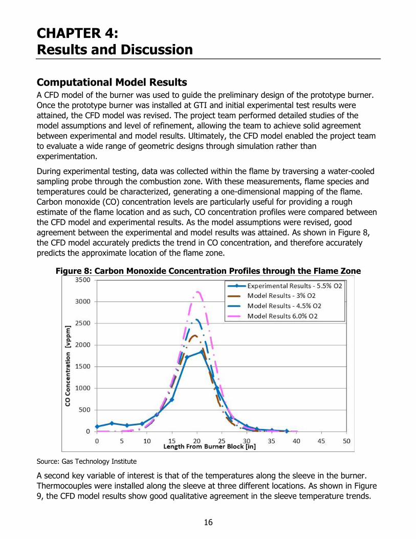
During experimental testing, data was collected within the flame by traversing a water-cooled
sampling probe through the combustion zone. With these measurements, flame species and
temperatures could be characterized, generating a one-dimensional mapping of the flame.
Carbon monoxide (CO) concentration levels are particularly useful for providing a rough
estimate of the flame location and as such, CO concentration profiles were compared between
the CFD model and experimental results. As the model assumptions were revised, good
agreement between the experimental and model results was attained. As shown in Figure 8,
the CFD model accurately predicts the trend in CO concentration, and therefore accurately
predicts the approximate location of the flame zone.
Figure 8: Carbon Monoxide Concentration Profiles through the Flame Zone
Source: Gas Technology Institute
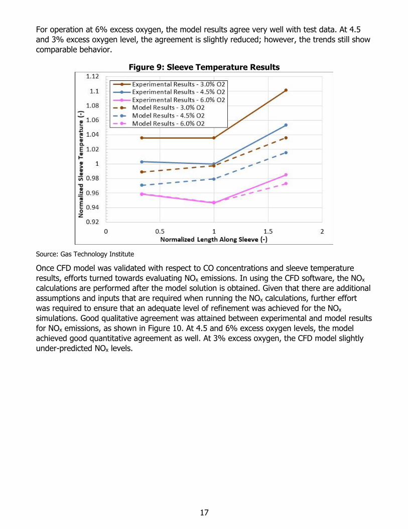
A second key variable of interest is that of the temperatures along the sleeve in the burner.
Thermocouples were installed along the sleeve at three different locations. As shown in Figure
9, the CFD model results show good qualitative agreement in the sleeve temperature trends.
17
For operation at 6% excess oxygen, the model results agree very well with test data. At 4.5
and 3% excess oxygen level, the agreement is slightly reduced; however, the trends still show
comparable behavior.
Figure 9: Sleeve Temperature Results
Source: Gas Technology Institute
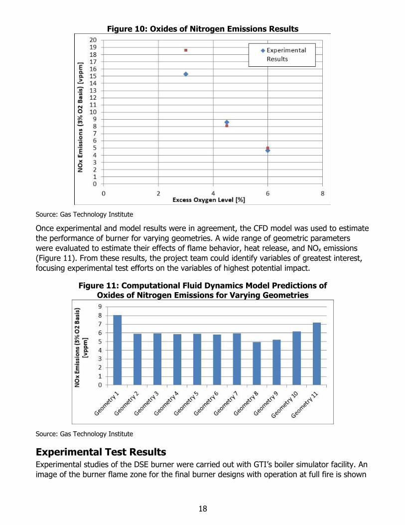
Once CFD model was validated with respect to CO concentrations and sleeve temperature
results, efforts turned towards evaluating NOx emissions. In using the CFD software, the NOx
calculations are performed after the model solution is obtained. Given that there are additional
assumptions and inputs that are required when running the NOx calculations, further effort
was required to ensure that an adequate level of refinement was achieved for the NOx
simulations. Good qualitative agreement was attained between experimental and model results
for NOx emissions, as shown in Figure 10. At 4.5 and 6% excess oxygen levels, the model
achieved good quantitative agreement as well. At 3% excess oxygen, the CFD model slightly
under-predicted NOx levels.
18
Figure 10: Oxides of Nitrogen Emissions Results
Source: Gas Technology Institute
Once experimental and model results were in agreement, the CFD model was used to estimate
the performance of burner for varying geometries. A wide range of geometric parameters
were evaluated to estimate their effects of flame behavior, heat release, and NOx emissions
(Figure 11). From these results, the project team could identify variables of greatest interest,
focusing experimental test efforts on the variables of highest potential impact.
Figure 11: Computational Fluid Dynamics Model Predictions of Oxides of Nitrogen Emissions for Varying Geometries
Source: Gas Technology Institute
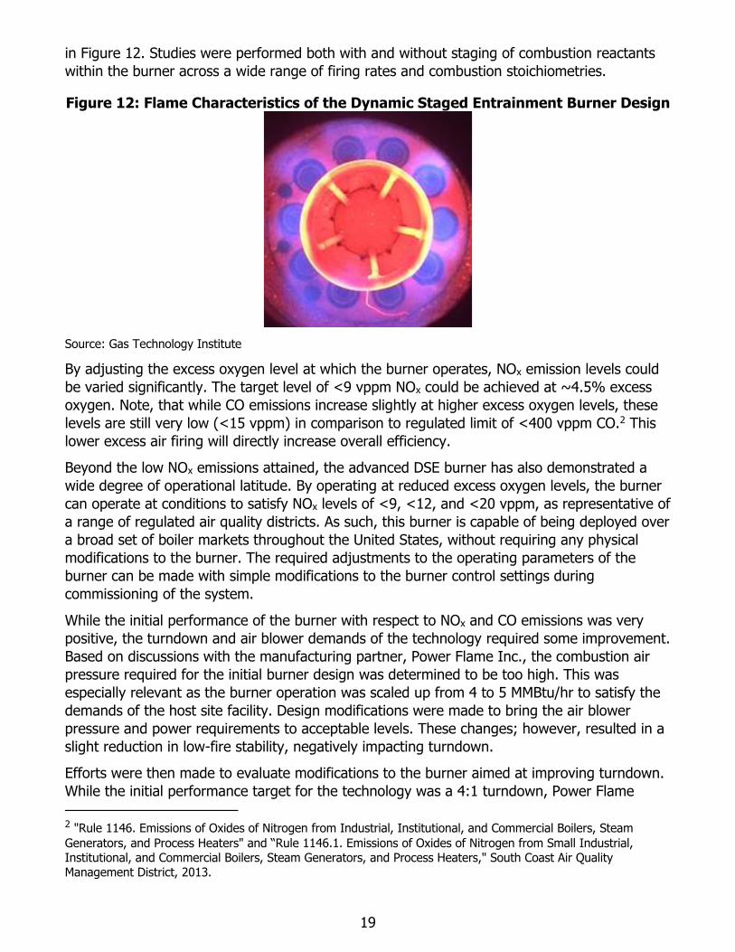
Experimental Test Results Experimental studies of the DSE burner were carried out with GTI’s boiler simulator facility. An
image of the burner flame zone for the final burner designs with operation at full fire is shown
19
in Figure 12. Studies were performed both with and without staging of combustion reactants
within the burner across a wide range of firing rates and combustion stoichiometries.
Figure 12: Flame Characteristics of the Dynamic Staged Entrainment Burner Design
Source: Gas Technology Institute
By adjusting the excess oxygen level at which the burner operates, NOx emission levels could
be varied significantly. The target level of <9 vppm NOx could be achieved at ~4.5% excess
oxygen. Note, that while CO emissions increase slightly at higher excess oxygen levels, these
levels are still very low (<15 vppm) in comparison to regulated limit of <400 vppm CO.2 This
lower excess air firing will directly increase overall efficiency.
Beyond the low NOx emissions attained, the advanced DSE burner has also demonstrated a
wide degree of operational latitude. By operating at reduced excess oxygen levels, the burner
can operate at conditions to satisfy NOx levels of <9, <12, and <20 vppm, as representative of
a range of regulated air quality districts. As such, this burner is capable of being deployed over
a broad set of boiler markets throughout the United States, without requiring any physical
modifications to the burner. The required adjustments to the operating parameters of the
burner can be made with simple modifications to the burner control settings during
commissioning of the system.
While the initial performance of the burner with respect to NOx and CO emissions was very
positive, the turndown and air blower demands of the technology required some improvement.
Based on discussions with the manufacturing partner, Power Flame Inc., the combustion air
pressure required for the initial burner design was determined to be too high. This was
especially relevant as the burner operation was scaled up from 4 to 5 MMBtu/hr to satisfy the
demands of the host site facility. Design modifications were made to bring the air blower
pressure and power requirements to acceptable levels. These changes; however, resulted in a
slight reduction in low-fire stability, negatively impacting turndown.
Efforts were then made to evaluate modifications to the burner aimed at improving turndown.
While the initial performance target for the technology was a 4:1 turndown, Power Flame
2 "Rule 1146. Emissions of Oxides of Nitrogen from Industrial, Institutional, and Commercial Boilers, Steam
Generators, and Process Heaters" and “Rule 1146.1. Emissions of Oxides of Nitrogen from Small Industrial, Institutional, and Commercial Boilers, Steam Generators, and Process Heaters," South Coast Air Quality Management District, 2013.
20
indicated that a higher turndown level would be desirable. To enhance the turndown
capability, geometric changes were needed to enhance stability at low fire. However, such
changes tend to have an opposing effect on NOx emissions, and as such, thorough studies
were performed to optimize the design to achieve the required turndown targets without
sacrificing performance with respect to NOx and CO emissions.
While the NOx and CO emissions for the final burner design are somewhat higher in
comparison to the results for the initial design for a given excess oxygen level, the turndown
and air blower demands are significantly improved. Further, the final burner configuration still
exhibits a wide range of operational latitude for satisfying varying regulatory NOx levels.
Additionally, CO levels remain very low across the operational range. Across the wide
operating domain, CO emissions are below 15 vppm for nearly all conditions.
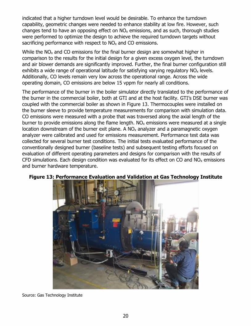
The performance of the burner in the boiler simulator directly translated to the performance of
the burner in the commercial boiler, both at GTI and at the host facility. GTI’s DSE burner was
coupled with the commercial boiler as shown in Figure 13. Thermocouples were installed on
the burner sleeve to provide temperature measurements for comparison with simulation data.
CO emissions were measured with a probe that was traversed along the axial length of the
burner to provide emissions along the flame length. NOx emissions were measured at a single
location downstream of the burner exit plane. A NOx analyzer and a paramagnetic oxygen
analyzer were calibrated and used for emissions measurement. Performance test data was
collected for several burner test conditions. The initial tests evaluated performance of the
conventionally designed burner (baseline tests) and subsequent testing efforts focused on
evaluation of different operating parameters and designs for comparison with the results of
CFD simulations. Each design condition was evaluated for its effect on CO and NOx emissions
and burner hardware temperature.
Figure 13: Performance Evaluation and Validation at Gas Technology Institute
Source: Gas Technology Institute
21
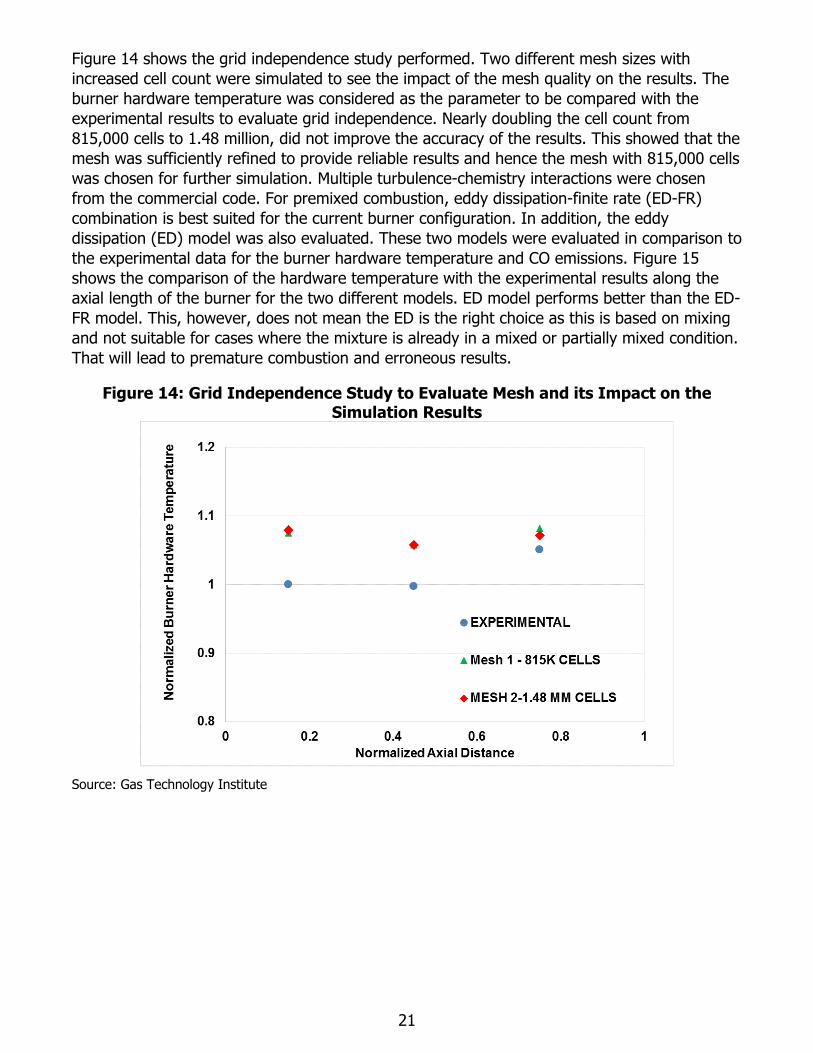
Figure 14 shows the grid independence study performed. Two different mesh sizes with
increased cell count were simulated to see the impact of the mesh quality on the results. The
burner hardware temperature was considered as the parameter to be compared with the
experimental results to evaluate grid independence. Nearly doubling the cell count from
815,000 cells to 1.48 million, did not improve the accuracy of the results. This showed that the
mesh was sufficiently refined to provide reliable results and hence the mesh with 815,000 cells
was chosen for further simulation. Multiple turbulence-chemistry interactions were chosen
from the commercial code. For premixed combustion, eddy dissipation-finite rate (ED-FR)
combination is best suited for the current burner configuration. In addition, the eddy
dissipation (ED) model was also evaluated. These two models were evaluated in comparison to
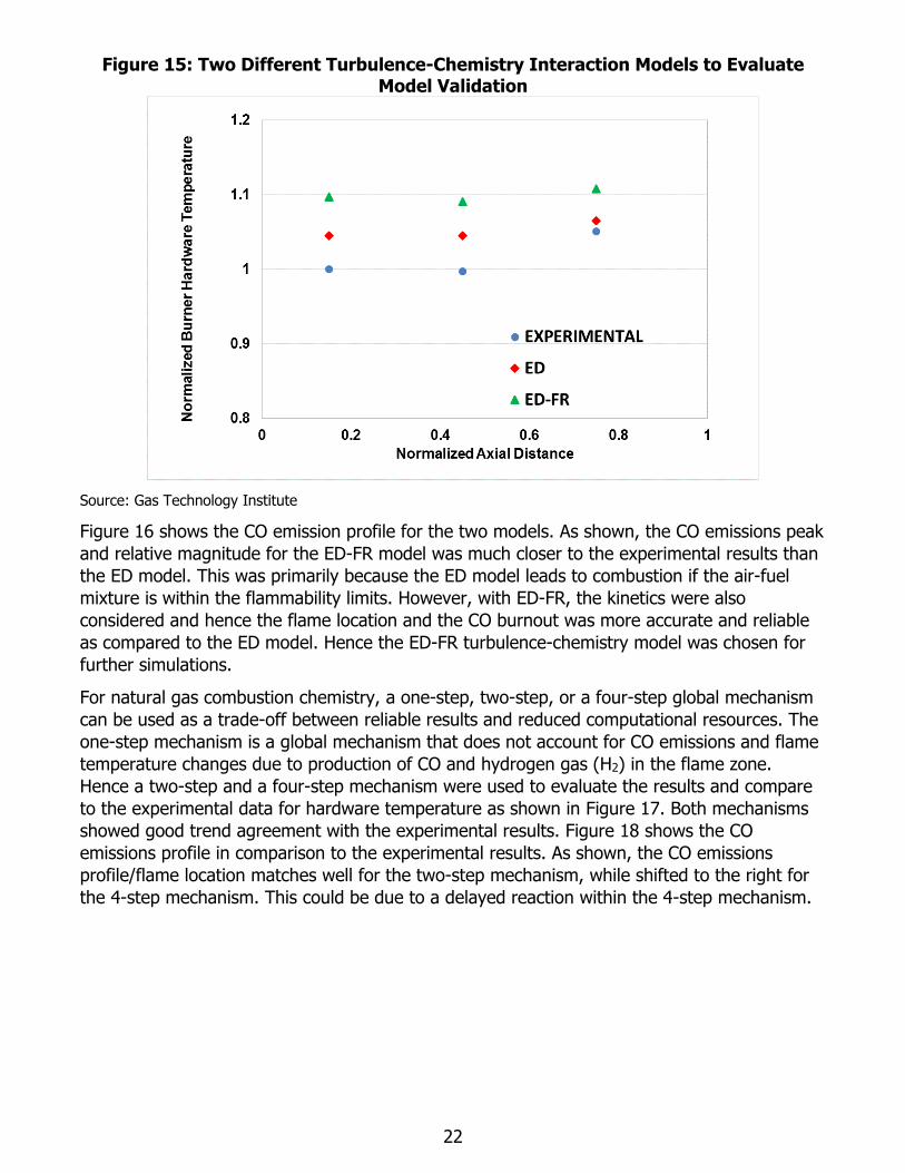
the experimental data for the burner hardware temperature and CO emissions. Figure 15
shows the comparison of the hardware temperature with the experimental results along the
axial length of the burner for the two different models. ED model performs better than the ED-
FR model. This, however, does not mean the ED is the right choice as this is based on mixing
and not suitable for cases where the mixture is already in a mixed or partially mixed condition.
That will lead to premature combustion and erroneous results.
Figure 14: Grid Independence Study to Evaluate Mesh and its Impact on the Simulation Results
Source: Gas Technology Institute
22
Figure 15: Two Different Turbulence-Chemistry Interaction Models to Evaluate Model Validation
Source: Gas Technology Institute
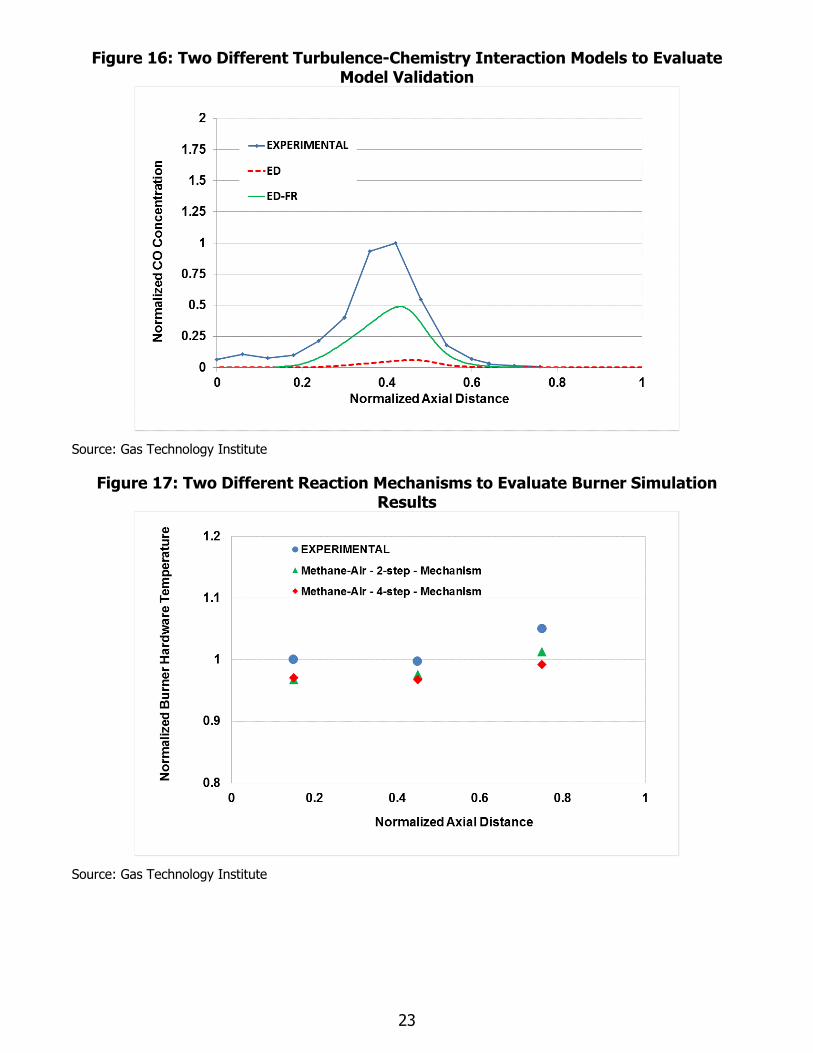
Figure 16 shows the CO emission profile for the two models. As shown, the CO emissions peak
and relative magnitude for the ED-FR model was much closer to the experimental results than
the ED model. This was primarily because the ED model leads to combustion if the air-fuel
mixture is within the flammability limits. However, with ED-FR, the kinetics were also
considered and hence the flame location and the CO burnout was more accurate and reliable
as compared to the ED model. Hence the ED-FR turbulence-chemistry model was chosen for
further simulations.
For natural gas combustion chemistry, a one-step, two-step, or a four-step global mechanism
can be used as a trade-off between reliable results and reduced computational resources. The
one-step mechanism is a global mechanism that does not account for CO emissions and flame
temperature changes due to production of CO and hydrogen gas (H2) in the flame zone.
Hence a two-step and a four-step mechanism were used to evaluate the results and compare
to the experimental data for hardware temperature as shown in Figure 17. Both mechanisms
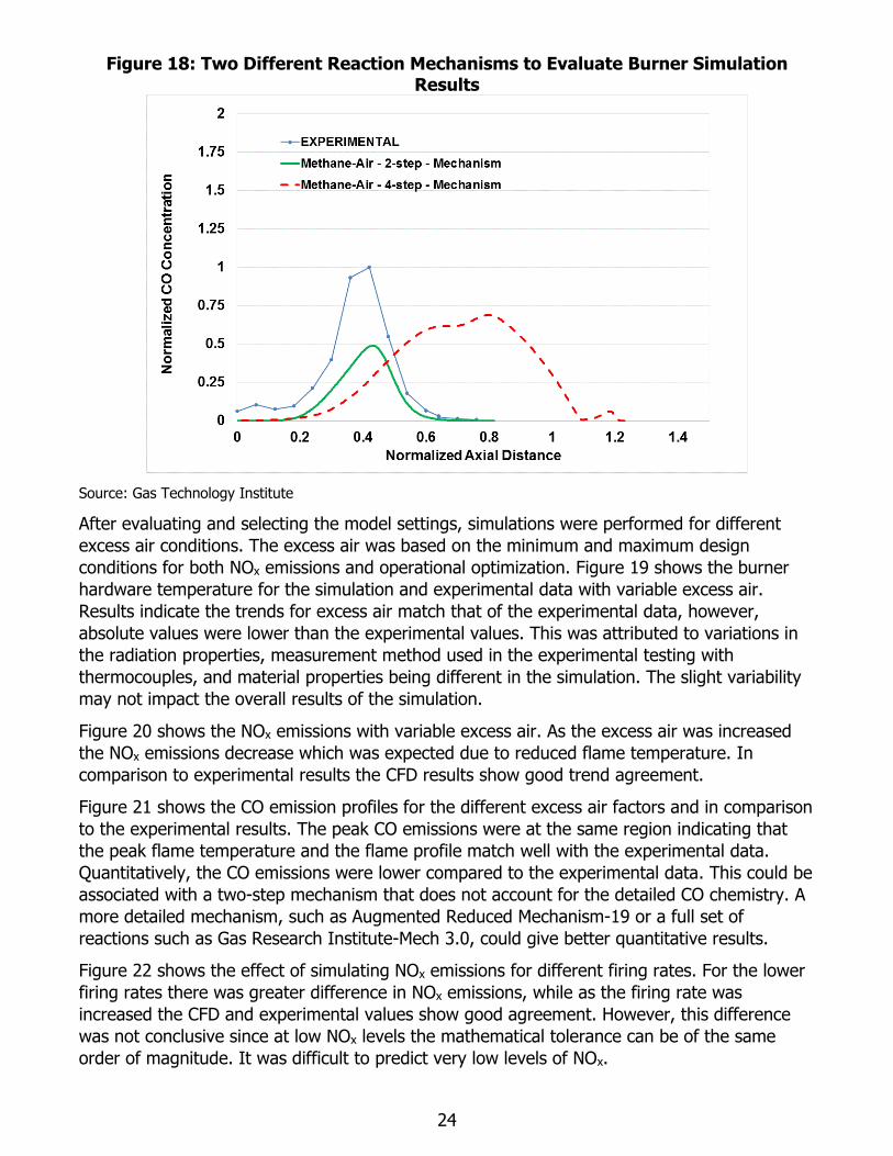
showed good trend agreement with the experimental results. Figure 18 shows the CO
emissions profile in comparison to the experimental results. As shown, the CO emissions
profile/flame location matches well for the two-step mechanism, while shifted to the right for
the 4-step mechanism. This could be due to a delayed reaction within the 4-step mechanism.
23
Figure 16: Two Different Turbulence-Chemistry Interaction Models to Evaluate Model Validation
Source: Gas Technology Institute
Figure 17: Two Different Reaction Mechanisms to Evaluate Burner Simulation Results
Source: Gas Technology Institute
24
Figure 18: Two Different Reaction Mechanisms to Evaluate Burner Simulation Results
Source: Gas Technology Institute
After evaluating and selecting the model settings, simulations were performed for different
excess air conditions. The excess air was based on the minimum and maximum design
conditions for both NOx emissions and operational optimization. Figure 19 shows the burner
hardware temperature for the simulation and experimental data with variable excess air.
Results indicate the trends for excess air match that of the experimental data, however,
absolute values were lower than the experimental values. This was attributed to variations in
the radiation properties, measurement method used in the experimental testing with
thermocouples, and material properties being different in the simulation. The slight variability
may not impact the overall results of the simulation.
Figure 20 shows the NOx emissions with variable excess air. As the excess air was increased
the NOx emissions decrease which was expected due to reduced flame temperature. In
comparison to experimental results the CFD results show good trend agreement.
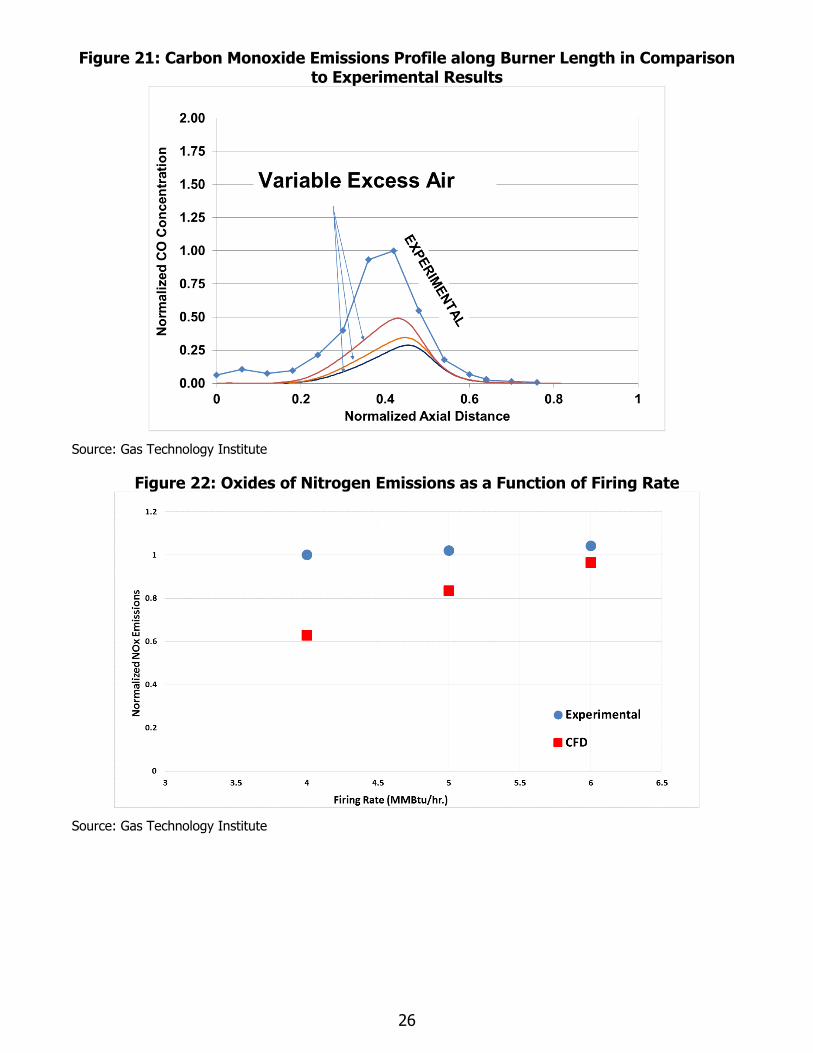
Figure 21 shows the CO emission profiles for the different excess air factors and in comparison
to the experimental results. The peak CO emissions were at the same region indicating that
the peak flame temperature and the flame profile match well with the experimental data.
Quantitatively, the CO emissions were lower compared to the experimental data. This could be
associated with a two-step mechanism that does not account for the detailed CO chemistry. A
more detailed mechanism, such as Augmented Reduced Mechanism-19 or a full set of
reactions such as Gas Research Institute-Mech 3.0, could give better quantitative results.
Figure 22 shows the effect of simulating NOx emissions for different firing rates. For the lower
firing rates there was greater difference in NOx emissions, while as the firing rate was
increased the CFD and experimental values show good agreement. However, this difference
was not conclusive since at low NOx levels the mathematical tolerance can be of the same
order of magnitude. It was difficult to predict very low levels of NOx.

25
Figure 19: Burner Hardware Temperature Compared to Experimental Data for Varying Excess Air
Source: Gas Technology Institute
Figure 20: Comparison of Oxides of Nitrogen Emissions with Experimental Results for Excess Air Factors
Source: Gas Technology Institute
26
Figure 21: Carbon Monoxide Emissions Profile along Burner Length in Comparison to Experimental Results
Source: Gas Technology Institute
Figure 22: Oxides of Nitrogen Emissions as a Function of Firing Rate
Source: Gas Technology Institute
27
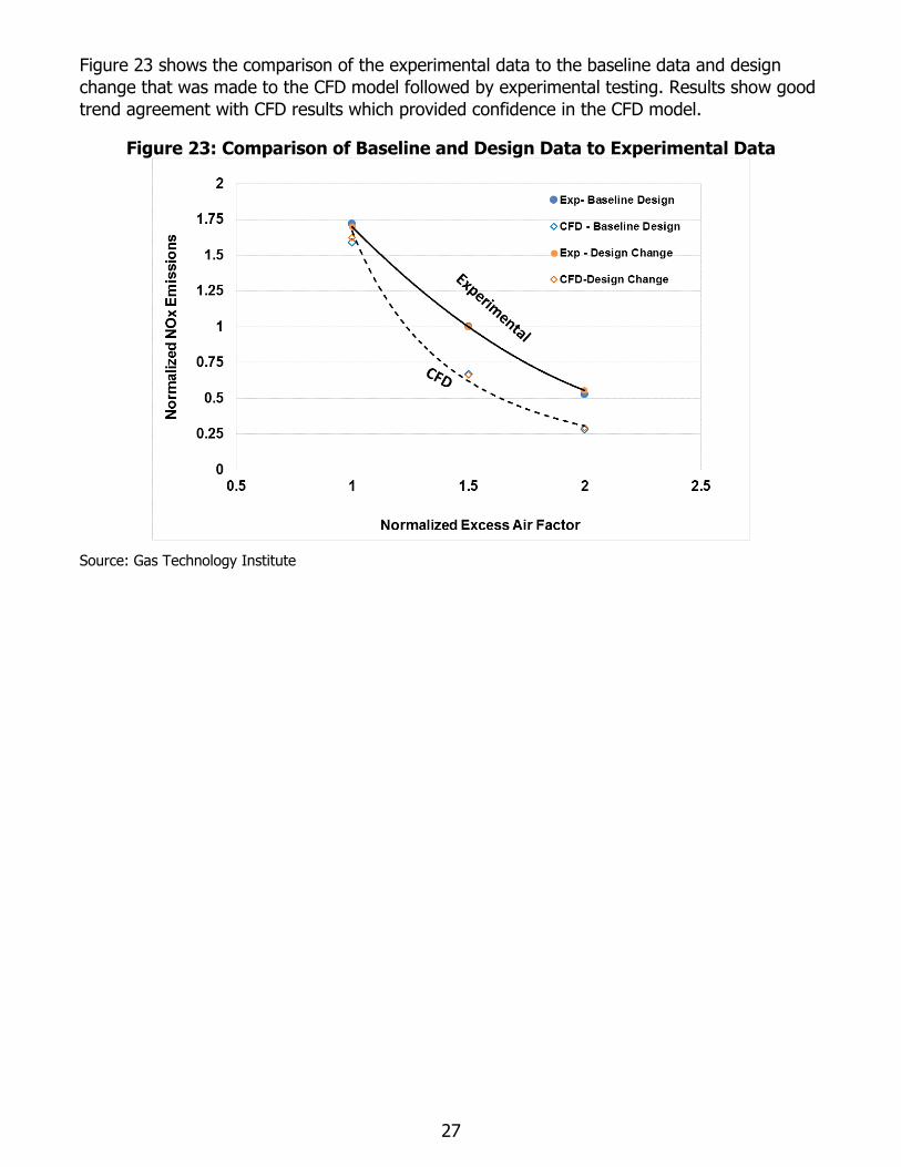
Figure 23 shows the comparison of the experimental data to the baseline data and design
change that was made to the CFD model followed by experimental testing. Results show good
trend agreement with CFD results which provided confidence in the CFD model.
Figure 23: Comparison of Baseline and Design Data to Experimental Data
Source: Gas Technology Institute
28
CHAPTER 5: Benefits of the Technology
Laboratory testing of the DSE burner technology has demonstrated the ability to achieve NOx
emissions below 9 vppm without the use of SCR, FGR, or HEA. The technology therefore offers
a new pathway for commercial and industrial boiler operators to achieve NOx emission
reductions mandated by current and future regulations at a lower cost and with higher energy
efficiency than is possible with current commercially available NOx mitigation strategies.
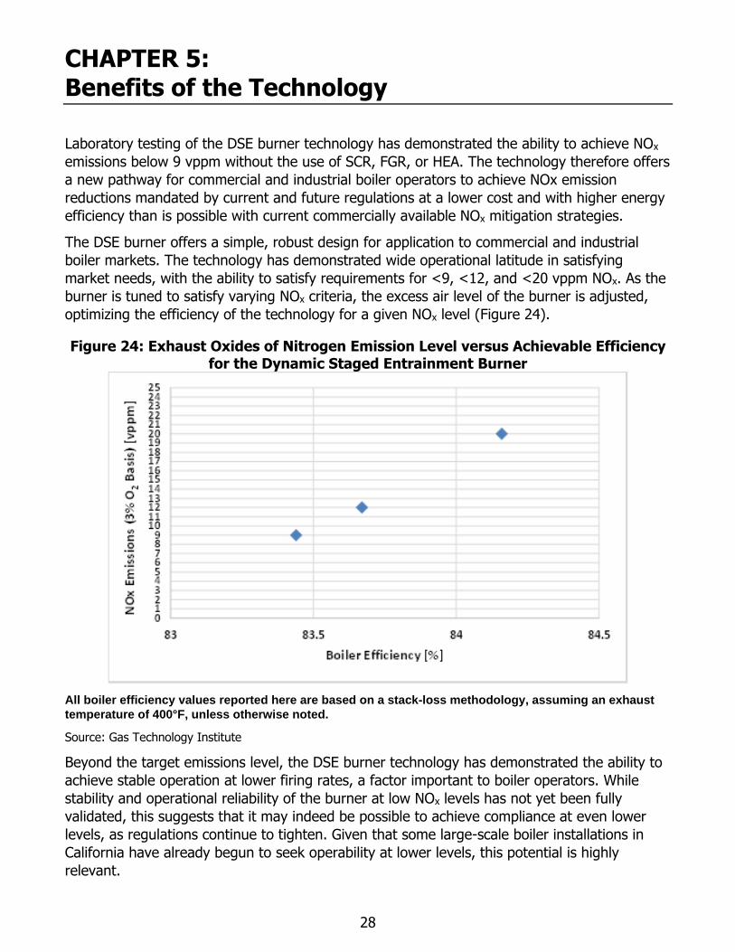
The DSE burner offers a simple, robust design for application to commercial and industrial
boiler markets. The technology has demonstrated wide operational latitude in satisfying
market needs, with the ability to satisfy requirements for <9, <12, and <20 vppm NOx. As the
burner is tuned to satisfy varying NOx criteria, the excess air level of the burner is adjusted,
optimizing the efficiency of the technology for a given NOx level (Figure 24).
Figure 24: Exhaust Oxides of Nitrogen Emission Level versus Achievable Efficiency for the Dynamic Staged Entrainment Burner
All boiler efficiency values reported here are based on a stack-loss methodology, assuming an exhaust
temperature of 400°F, unless otherwise noted.
Source: Gas Technology Institute
Beyond the target emissions level, the DSE burner technology has demonstrated the ability to
achieve stable operation at lower firing rates, a factor important to boiler operators. While
stability and operational reliability of the burner at low NOx levels has not yet been fully
validated, this suggests that it may indeed be possible to achieve compliance at even lower
levels, as regulations continue to tighten. Given that some large-scale boiler installations in
California have already begun to seek operability at lower levels, this potential is highly
relevant.
29
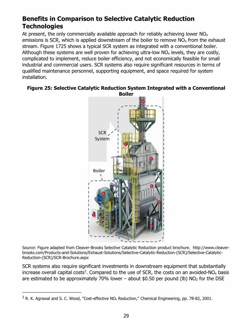
Benefits in Comparison to Selective Catalytic Reduction Technologies At present, the only commercially available approach for reliably achieving lower NOx
emissions is SCR, which is applied downstream of the boiler to remove NOx from the exhaust
stream. Figure 1725 shows a typical SCR system as integrated with a conventional boiler.
Although these systems are well proven for achieving ultra-low NOx levels, they are costly,
complicated to implement, reduce boiler efficiency, and not economically feasible for small
industrial and commercial users. SCR systems also require significant resources in terms of
qualified maintenance personnel, supporting equipment, and space required for system
installation.
Figure 25: Selective Catalytic Reduction System Integrated with a Conventional Boiler
Source: Figure adapted from Cleaver-Brooks Selective Catalytic Reduction product brochure. http://www.cleaver-brooks.com/Products-and-Solutions/Exhaust-Solutions/Selective-Catalytic-Reduction-(SCR)/Selective-Catalytic-Reduction-(SCR)/SCR-Brochure.aspx
SCR systems also require significant investments in downstream equipment that substantially
increase overall capital costs3. Compared to the use of SCR, the costs on an avoided-NOx basis
are estimated to be approximately 70% lower – about $0.50 per pound (lb) NO2 for the DSE
3 R. K. Agrawal and S. C. Wood, "Cost-effective NOx Reduction," Chemical Engineering, pp. 78-82, 2001.
30
burner technology developed within this project. Moreover, the capital cost for the DSE burner
is anticipated to be no more than an equivalent sized conventional low-NOx burner.
Beyond the high costs of SCR systems, there are further disadvantages in terms of efficiency.
Net fuel and electricity consumption rates are higher for SCR systems, resulting in higher
operating costs and GHG emissions for the same steam or hot water output. To achieve air
quality improvement targets and regulatory compliance, efficient and cost-effective pollution
control technologies need to be deployed to the market. The DSE burner technology has the
potential save 2.5 million tons of NOx annually in California alone, by achieving robust
operation with NOx emissions below 9 vppm as based on information from California Air
Resource Board databases. Broader deployment throughout North American markets will have
even broader impact on NOx mitigation, energy savings, and greenhouse gas reductions.
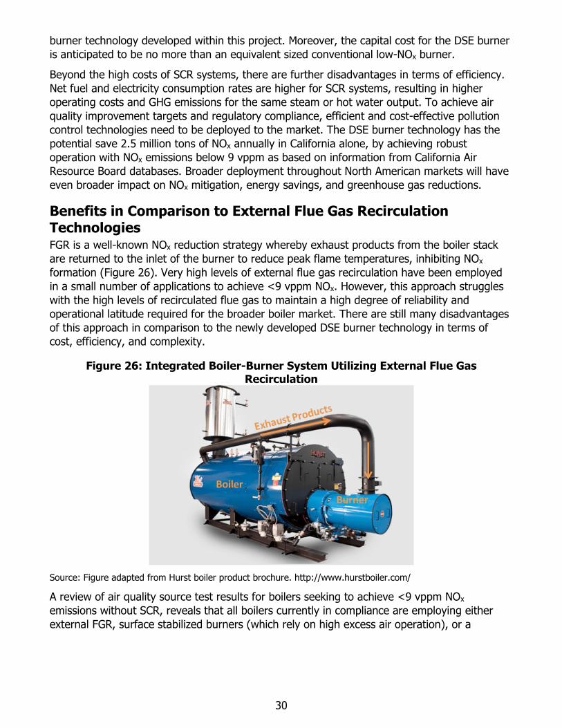
Benefits in Comparison to External Flue Gas Recirculation Technologies FGR is a well-known NOx reduction strategy whereby exhaust products from the boiler stack
are returned to the inlet of the burner to reduce peak flame temperatures, inhibiting NOx
formation (Figure 26). Very high levels of external flue gas recirculation have been employed
in a small number of applications to achieve <9 vppm NOx. However, this approach struggles
with the high levels of recirculated flue gas to maintain a high degree of reliability and
operational latitude required for the broader boiler market. There are still many disadvantages
of this approach in comparison to the newly developed DSE burner technology in terms of
cost, efficiency, and complexity.
Figure 26: Integrated Boiler-Burner System Utilizing External Flue Gas Recirculation
Source: Figure adapted from Hurst boiler product brochure. http://www.hurstboiler.com/
A review of air quality source test results for boilers seeking to achieve <9 vppm NOx
emissions without SCR, reveals that all boilers currently in compliance are employing either
external FGR, surface stabilized burners (which rely on high excess air operation), or a
31
combination of these technologies4. Thus, for <9 vppm NOx operation, FGR systems are well
proven and commonplace.
The DSE burner developed within this project demonstrated the ability to achieve operation at
<9 vppm with high efficiency, and without the need for FGR. This newly developed burner
technology avoids the added cost required for the supporting duct work, high temperature
exhaust blower, and additional controls associated with FGR systems. Moreover, it avoids the
added complexities associated with cold-startup and condensation challenges that arise with
FGR systems.
The DSE burner also achieves efficiency gains relative to FGR systems, both in terms of
electricity and natural gas consumption. External FGR boiler systems consume up to 50%
more electricity than conventional boilers, as a result of the power required to drive the high
temperature blower to return exhaust products from the boiler stack to the inlet of the burner.
Regarding fuel consumption, the DSE burner achieves comparable or slightly increased
efficiency as well. External FGR systems typically operate at excess air levels in the range of
28% to 32% (5.0% to 5.5% excess oxygen) to achieve <9 vppm NOx5. The newly developed
DSE burner has demonstrated <9 vppm NOx with operation at 24% to 28% excess air (4.5%
to 5% excess oxygen), thereby achieving comparable, or improved, efficiency relative to FGR
systems, without the added equipment cost and electricity consumption.
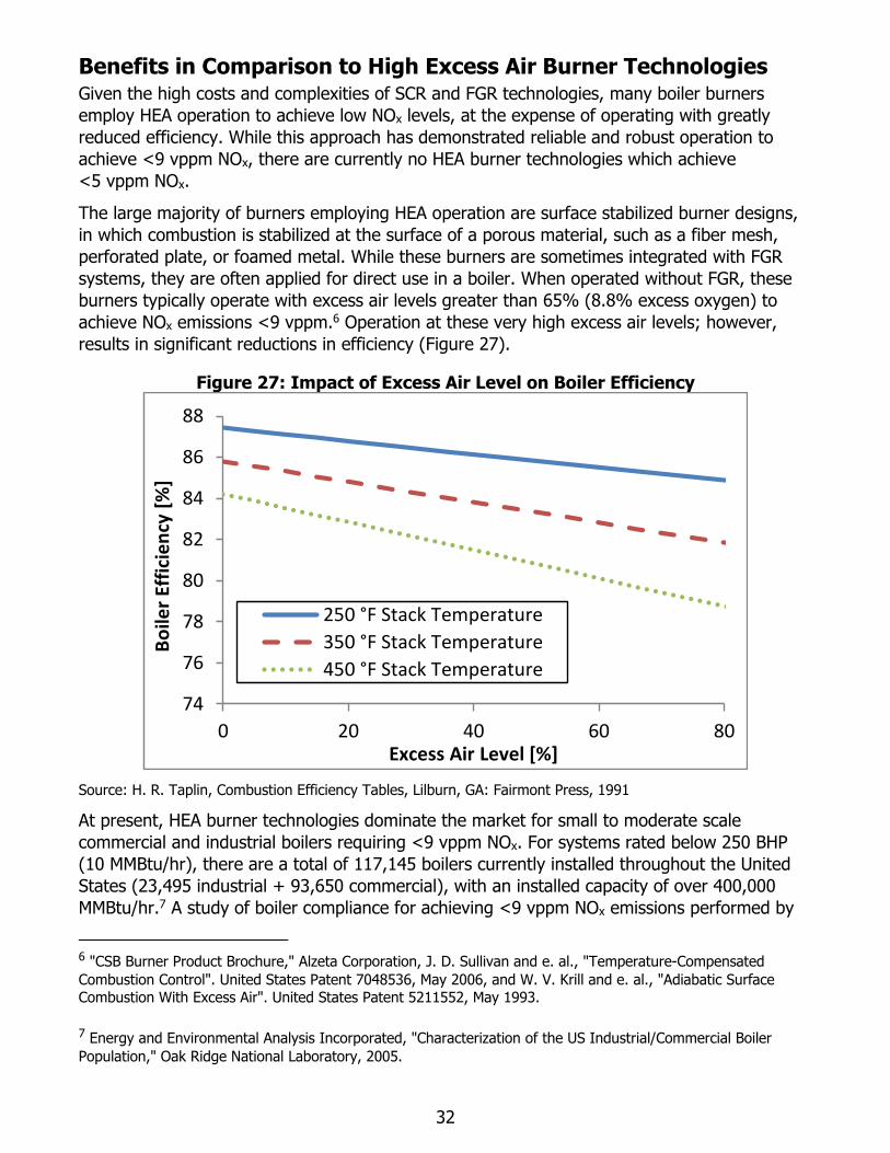
The system performance benefits of the DSE burner technology in comparison to conventional
low-NOx FGR systems are summarized in Table 3.
Table 3: Comparison of the DSE Burner to a Conventional FGR Burner, Operation at <9 vppm NOx
Operating Parameter Units Conventional Low-
NOx Burner (with FGR)
DSE Burner (9 vppm
NOx)
Full Fire MBtu/hr 5,000 5,000
Flue Gas Recirculation - Yes No
Turndown - 4:1 5:1
Excess Oxygen Level % 5.5 5.0
Boiler Efficiency % 83.2 83.4
NOx (at 3% O2) vppm <9 <9
CO (at 3% O2) vppm <200 <200
Blower Power HP 5 to 7.5 (estimate) 2.5
Information adapted from product specifications of commercially available burner products.
Source: Gas Technology Institute
4 W. Barcikowski, K. Orellana and G. Quinn., "Implementation Assessment Report on Ultra-Low NOx Burners
subject to Rules 1146 and 1146.1," South Coast Air Quality Management District, 2010.
5 "Suggested Specification for Model NVC2 Through NVC6 Ultra Low NOx Gas Burners," in Product Specifications,
Power Flame Incorporated, 2007.
32
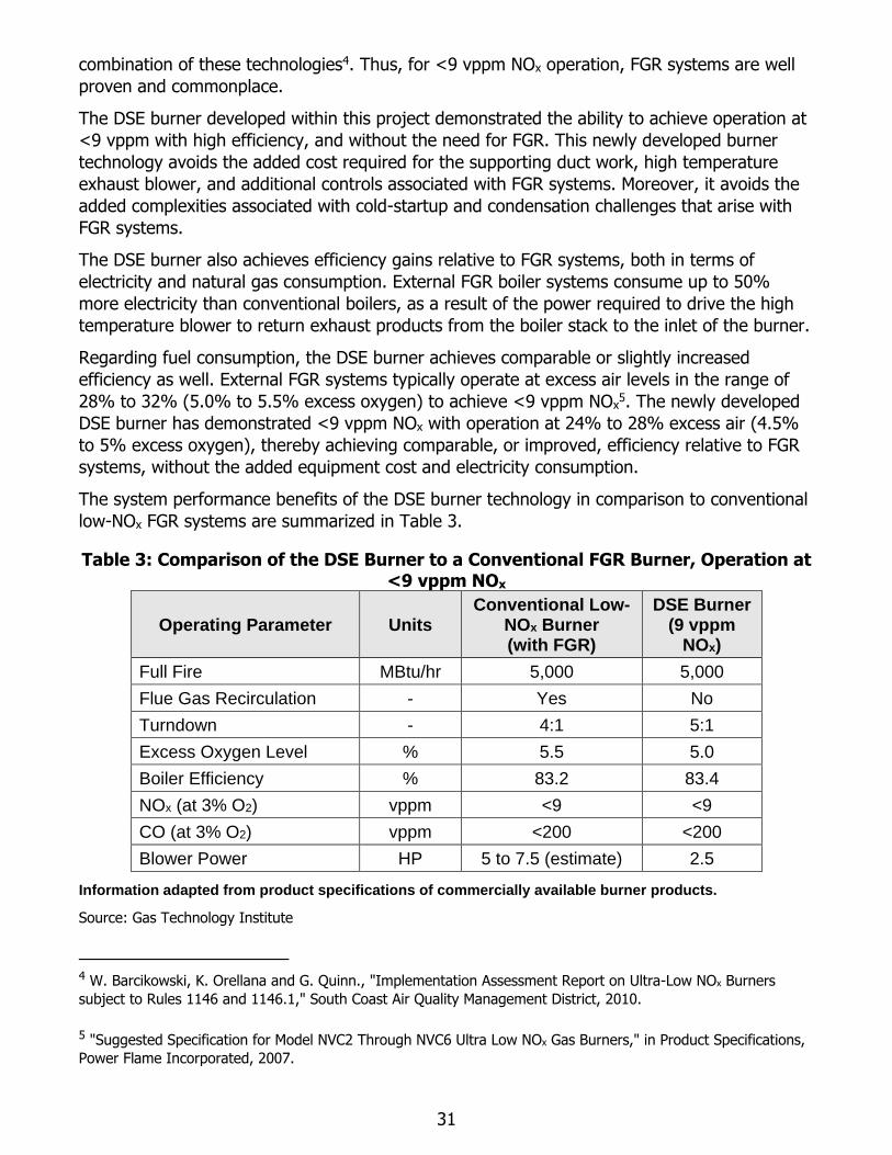
Benefits in Comparison to High Excess Air Burner Technologies Given the high costs and complexities of SCR and FGR technologies, many boiler burners
employ HEA operation to achieve low NOx levels, at the expense of operating with greatly
reduced efficiency. While this approach has demonstrated reliable and robust operation to
achieve <9 vppm NOx, there are currently no HEA burner technologies which achieve
<5 vppm NOx.
The large majority of burners employing HEA operation are surface stabilized burner designs,
in which combustion is stabilized at the surface of a porous material, such as a fiber mesh,
perforated plate, or foamed metal. While these burners are sometimes integrated with FGR
systems, they are often applied for direct use in a boiler. When operated without FGR, these
burners typically operate with excess air levels greater than 65% (8.8% excess oxygen) to
achieve NOx emissions <9 vppm.6 Operation at these very high excess air levels; however,
results in significant reductions in efficiency (Figure 27).
Figure 27: Impact of Excess Air Level on Boiler Efficiency
Source: H. R. Taplin, Combustion Efficiency Tables, Lilburn, GA: Fairmont Press, 1991
At present, HEA burner technologies dominate the market for small to moderate scale
commercial and industrial boilers requiring <9 vppm NOx. For systems rated below 250 BHP
(10 MMBtu/hr), there are a total of 117,145 boilers currently installed throughout the United
States (23,495 industrial + 93,650 commercial), with an installed capacity of over 400,000
MMBtu/hr.7 A study of boiler compliance for achieving <9 vppm NOx emissions performed by
6 "CSB Burner Product Brochure," Alzeta Corporation, J. D. Sullivan and e. al., "Temperature-Compensated
Combustion Control". United States Patent 7048536, May 2006, and W. V. Krill and e. al., "Adiabatic Surface Combustion With Excess Air". United States Patent 5211552, May 1993.
7 Energy and Environmental Analysis Incorporated, "Characterization of the US Industrial/Commercial Boiler
Population," Oak Ridge National Laboratory, 2005.
74
76
78
80
82
84
86
88
0 20 40 60 80
Bo
iler
Effi
cie
ncy
[%
]
Excess Air Level [%]
250 °F Stack Temperature
350 °F Stack Temperature
450 °F Stack Temperature
33
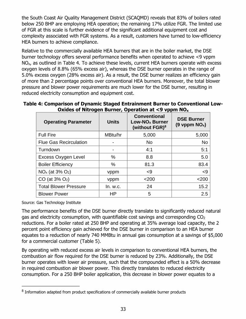
the South Coast Air Quality Management District (SCAQMD) reveals that 83% of boilers rated
below 250 BHP are employing HEA operation; the remaining 17% utilize FGR. The limited use
of FGR at this scale is further evidence of the significant additional equipment cost and
complexity associated with FGR systems. As a result, customers have turned to low-efficiency
HEA burners to achieve compliance.
Relative to the commercially available HEA burners that are in the boiler market, the DSE
burner technology offers several performance benefits when operated to achieve <9 vppm
NOx, as outlined in Table 4. To achieve these levels, current HEA burners operate with excess
oxygen levels of 8.8% (65% excess air), whereas the DSE burner operates in the range of
5.0% excess oxygen (28% excess air). As a result, the DSE burner realizes an efficiency gain
of more than 2 percentage points over conventional HEA burners. Moreover, the total blower
pressure and blower power requirements are much lower for the DSE burner, resulting in
reduced electricity consumption and equipment cost.
Table 4: Comparison of Dynamic Staged Entrainment Burner to Conventional Low-Oxides of Nitrogen Burner, Operation at <9 vppm NOx
Operating Parameter Units Conventional
Low-NOx Burner (without FGR)8
DSE Burner (9 vppm NOx)
Full Fire MBtu/hr 5,000 5,000
Flue Gas Recirculation - No No
Turndown - 4:1 5:1
Excess Oxygen Level % 8.8 5.0
Boiler Efficiency % 81.3 83.4
NOx (at 3% O2) vppm <9 <9
CO (at 3% O2) vppm <200 <200
Total Blower Pressure In. w.c. 24 15.2
Blower Power HP 5 2.5
Source: Gas Technology Institute
The performance benefits of the DSE burner directly translate to significantly reduced natural
gas and electricity consumption, with quantifiable cost savings and corresponding CO2
reductions. For a boiler rated at 250 BHP and operating at 35% average load capacity, the 2
percent point efficiency gain achieved for the DSE burner in comparison to an HEA burner
equates to a reduction of nearly 740 MMBtu in annual gas consumption at a savings of $5,000
for a commercial customer (Table 5).
By operating with reduced excess air levels in comparison to conventional HEA burners, the
combustion air flow required for the DSE burner is reduced by 23%. Additionally, the DSE
burner operates with lower air pressure, such that the compounded effect is a 50% decrease
in required combustion air blower power. This directly translates to reduced electricity
consumption. For a 250 BHP boiler application, this decrease in blower power equates to a
8 Information adapted from product specifications of commercially available burner products
34
reduction of nearly $1,500 in electricity costs annually for a commercial customer (Table 5).
Further, total annual greenhouse gas and NOx emissions is reduced by over 48 tons for a
boiler operating with a DSE burner rather than a conventional HEA burner.
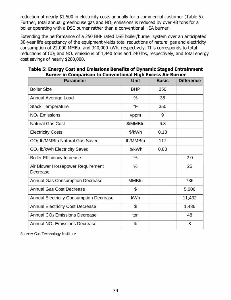
Extending the performance of a 250 BHP rated DSE boiler/burner system over an anticipated
30-year life expectancy of the equipment yields total reductions of natural gas and electricity
consumption of 22,000 MMBtu and 340,000 kWh, respectively. This corresponds to total
reductions of CO2 and NOx emissions of 1,440 tons and 240 lbs, respectively, and total energy
cost savings of nearly $200,000.
Table 5: Energy Cost and Emissions Benefits of Dynamic Staged Entrainment Burner in Comparison to Conventional High Excess Air Burner
Parameter Unit Basis Difference
Boiler Size BHP 250
Annual Average Load % 35
Stack Temperature °F 350
NOx Emissions vppm 9
Natural Gas Cost $/MMBtu 6.8
Electricity Costs $/kWh 0.13
CO2 lb/MMBtu Natural Gas Saved lb/MMBtu 117
CO2 lb/kWh Electricity Saved lb/kWh 0.83
Boiler Efficiency Increase % 2.0
Air Blower Horsepower Requirement
Decrease
% 25
Annual Gas Consumption Decrease MMBtu 736
Annual Gas Cost Decrease $ 5,006
Annual Electricity Consumption Decrease kWh 11,432
Annual Electricity Cost Decrease $ 1,486
Annual CO2 Emissions Decrease ton 48
Annual NOx Emissions Decrease lb 8
Source: Gas Technology Institute
35
CHAPTER 6: Commercialization Status
Field Demonstration The laboratory testing and development efforts performed thus far have proven the
technological merits of the DSE burner. To further accelerate the technology towards market
deployment, the project team demonstrated the technology under real-world conditions at a
customer facility located in Santa Barbara, California. This high-visibility field demonstration
project is anticipated to build interest and transfer knowledge throughout commercial and
industrial boiler markets.
Commissioning
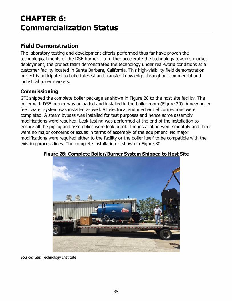
GTI shipped the complete boiler package as shown in Figure 28 to the host site facility. The
boiler with DSE burner was unloaded and installed in the boiler room (Figure 29). A new boiler
feed water system was installed as well. All electrical and mechanical connections were
completed. A steam bypass was installed for test purposes and hence some assembly
modifications were required. Leak testing was performed at the end of the installation to
ensure all the piping and assemblies were leak proof. The installation went smoothly and there
were no major concerns or issues in terms of assembly of the equipment. No major
modifications were required either to the facility or the boiler itself to be compatible with the
existing process lines. The complete installation is shown in Figure 30.
Figure 28: Complete Boiler/Burner System Shipped to Host Site
Source: Gas Technology Institute
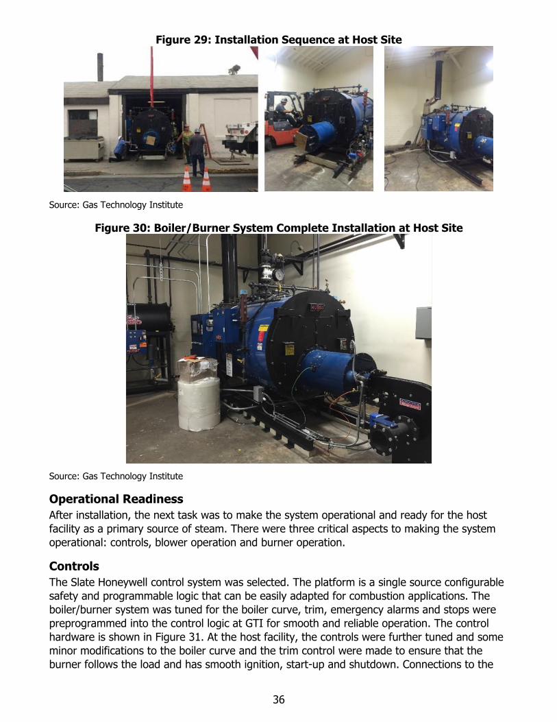
36
Figure 29: Installation Sequence at Host Site
Source: Gas Technology Institute
Figure 30: Boiler/Burner System Complete Installation at Host Site
Source: Gas Technology Institute
Operational Readiness
After installation, the next task was to make the system operational and ready for the host
facility as a primary source of steam. There were three critical aspects to making the system
operational: controls, blower operation and burner operation.
Controls
The Slate Honeywell control system was selected. The platform is a single source configurable
safety and programmable logic that can be easily adapted for combustion applications. The
boiler/burner system was tuned for the boiler curve, trim, emergency alarms and stops were
preprogrammed into the control logic at GTI for smooth and reliable operation. The control
hardware is shown in Figure 31. At the host facility, the controls were further tuned and some
minor modifications to the boiler curve and the trim control were made to ensure that the
burner follows the load and has smooth ignition, start-up and shutdown. Connections to the
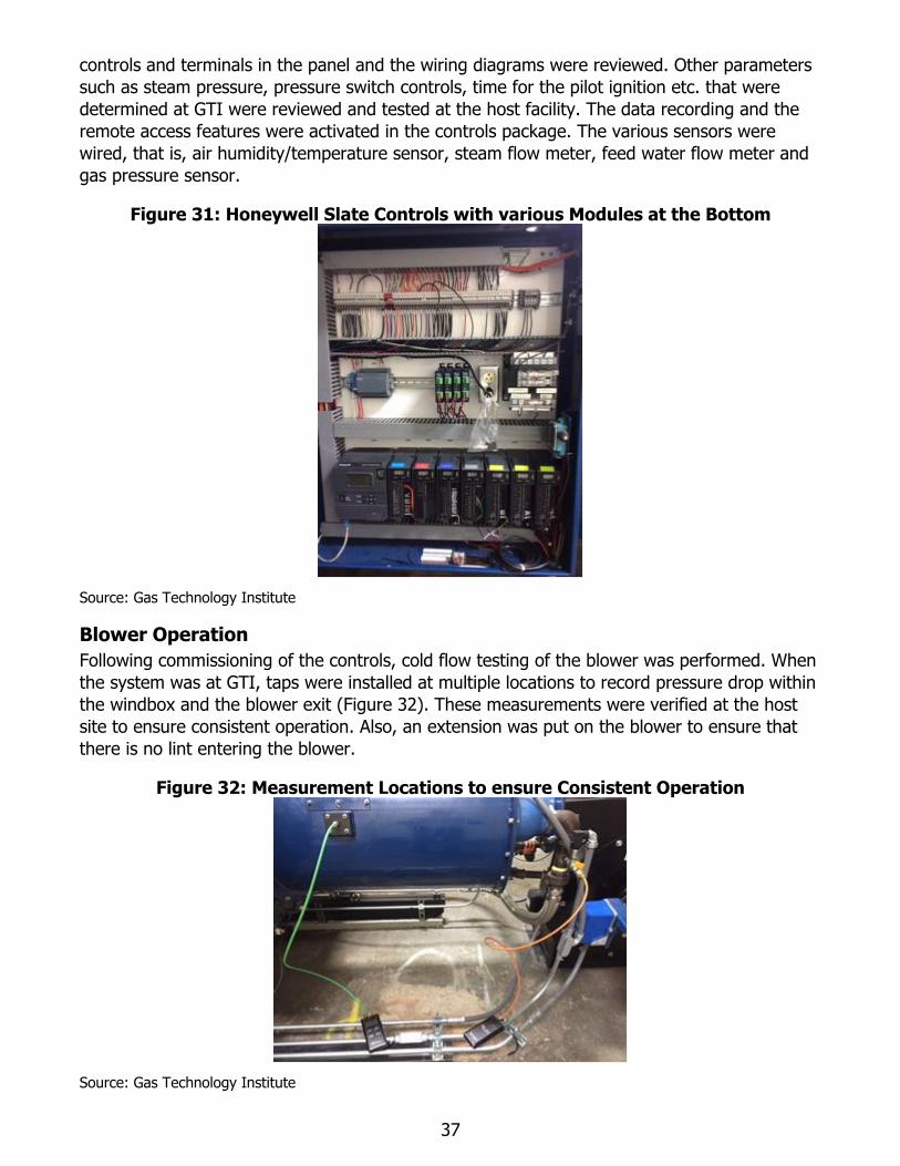
37
controls and terminals in the panel and the wiring diagrams were reviewed. Other parameters
such as steam pressure, pressure switch controls, time for the pilot ignition etc. that were
determined at GTI were reviewed and tested at the host facility. The data recording and the
remote access features were activated in the controls package. The various sensors were
wired, that is, air humidity/temperature sensor, steam flow meter, feed water flow meter and
gas pressure sensor.
Figure 31: Honeywell Slate Controls with various Modules at the Bottom
Source: Gas Technology Institute
Blower Operation
Following commissioning of the controls, cold flow testing of the blower was performed. When
the system was at GTI, taps were installed at multiple locations to record pressure drop within
the windbox and the blower exit (Figure 32). These measurements were verified at the host
site to ensure consistent operation. Also, an extension was put on the blower to ensure that
there is no lint entering the blower.
Figure 32: Measurement Locations to ensure Consistent Operation
Source: Gas Technology Institute
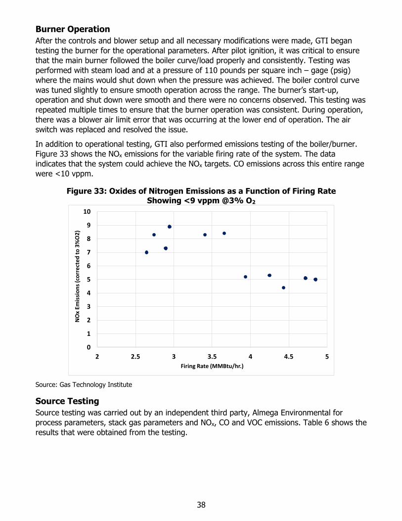
38
Burner Operation
After the controls and blower setup and all necessary modifications were made, GTI began
testing the burner for the operational parameters. After pilot ignition, it was critical to ensure
that the main burner followed the boiler curve/load properly and consistently. Testing was
performed with steam load and at a pressure of 110 pounds per square inch – gage (psig)
where the mains would shut down when the pressure was achieved. The boiler control curve
was tuned slightly to ensure smooth operation across the range. The burner’s start-up,
operation and shut down were smooth and there were no concerns observed. This testing was
repeated multiple times to ensure that the burner operation was consistent. During operation,
there was a blower air limit error that was occurring at the lower end of operation. The air
switch was replaced and resolved the issue.
In addition to operational testing, GTI also performed emissions testing of the boiler/burner.
Figure 33 shows the NOx emissions for the variable firing rate of the system. The data
indicates that the system could achieve the NOx targets. CO emissions across this entire range
were <10 vppm.
Figure 33: Oxides of Nitrogen Emissions as a Function of Firing Rate Showing <9 vppm @3% O2
Source: Gas Technology Institute
Source Testing
Source testing was carried out by an independent third party, Almega Environmental for
process parameters, stack gas parameters and NOx, CO and VOC emissions. Table 6 shows the
results that were obtained from the testing.
0
1
2
3
4
5
6
7
8
9
10
2 2.5 3 3.5 4 4.5 5
NO
x Em
issi
on
s (c
orr
ect
ed
to
3%
O2
)
Firing Rate (MMBtu/hr.)
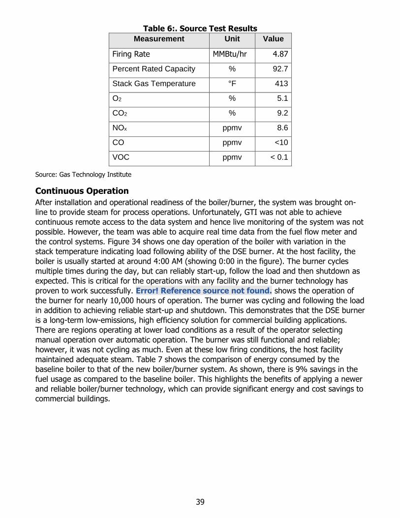
39
Table 6:. Source Test Results
Measurement Unit Value
Firing Rate MMBtu/hr 4.87
Percent Rated Capacity % 92.7
Stack Gas Temperature °F 413
O2 % 5.1
CO2 % 9.2
NOx ppmv 8.6
CO ppmv <10
VOC ppmv < 0.1
Source: Gas Technology Institute
Continuous Operation
After installation and operational readiness of the boiler/burner, the system was brought on-
line to provide steam for process operations. Unfortunately, GTI was not able to achieve
continuous remote access to the data system and hence live monitoring of the system was not
possible. However, the team was able to acquire real time data from the fuel flow meter and
the control systems. Figure 34 shows one day operation of the boiler with variation in the
stack temperature indicating load following ability of the DSE burner. At the host facility, the
boiler is usually started at around 4:00 AM (showing 0:00 in the figure). The burner cycles
multiple times during the day, but can reliably start-up, follow the load and then shutdown as
expected. This is critical for the operations with any facility and the burner technology has
proven to work successfully. Error! Reference source not found. shows the operation of
the burner for nearly 10,000 hours of operation. The burner was cycling and following the load
in addition to achieving reliable start-up and shutdown. This demonstrates that the DSE burner
is a long-term low-emissions, high efficiency solution for commercial building applications.
There are regions operating at lower load conditions as a result of the operator selecting
manual operation over automatic operation. The burner was still functional and reliable;
however, it was not cycling as much. Even at these low firing conditions, the host facility
maintained adequate steam. Table 7 shows the comparison of energy consumed by the
baseline boiler to that of the new boiler/burner system. As shown, there is 9% savings in the
fuel usage as compared to the baseline boiler. This highlights the benefits of applying a newer
and reliable boiler/burner technology, which can provide significant energy and cost savings to
commercial buildings.
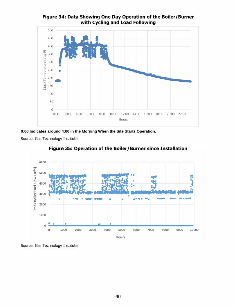
40
Figure 34: Data Showing One Day Operation of the Boiler/Burner with Cycling and Load Following
0:00 Indicates around 4:00 in the Morning When the Site Starts Operation.
Source: Gas Technology Institute
Figure 35: Operation of the Boiler/Burner since Installation
Source: Gas Technology Institute
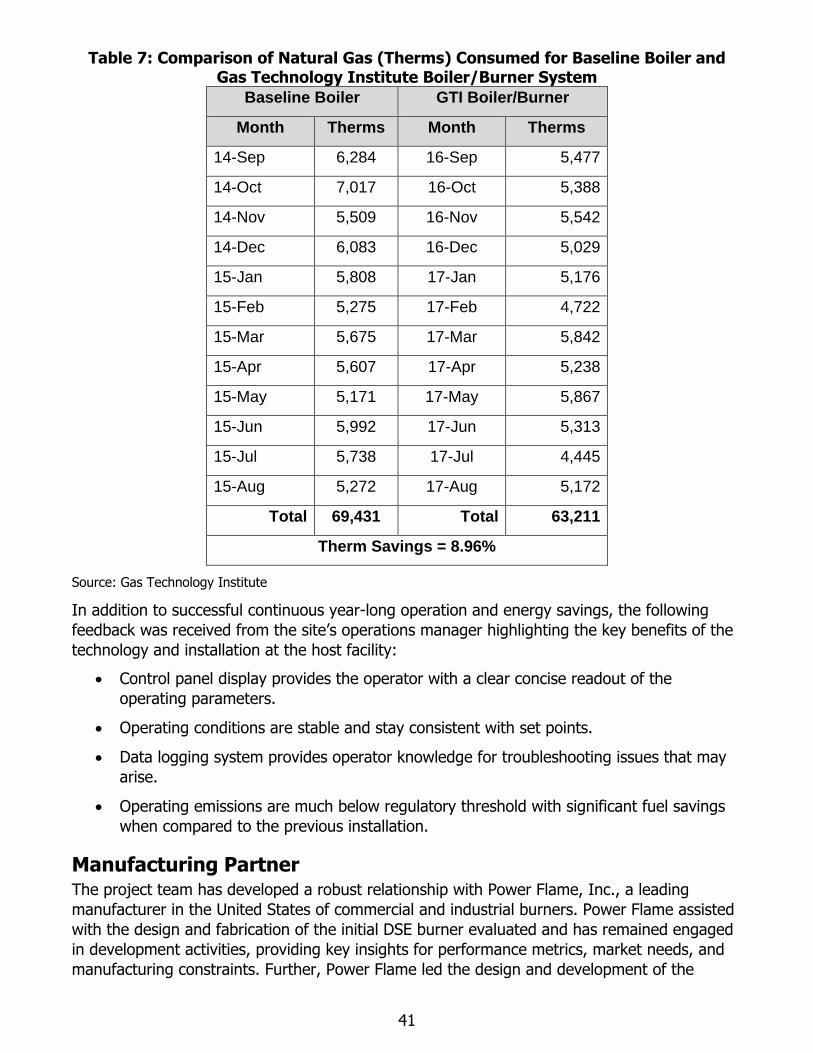
41
Table 7: Comparison of Natural Gas (Therms) Consumed for Baseline Boiler and Gas Technology Institute Boiler/Burner System
Baseline Boiler GTI Boiler/Burner
Month Therms Month Therms
14-Sep 6,284 16-Sep 5,477
14-Oct 7,017 16-Oct 5,388
14-Nov 5,509 16-Nov 5,542
14-Dec 6,083 16-Dec 5,029
15-Jan 5,808 17-Jan 5,176
15-Feb 5,275 17-Feb 4,722
15-Mar 5,675 17-Mar 5,842
15-Apr 5,607 17-Apr 5,238
15-May 5,171 17-May 5,867
15-Jun 5,992 17-Jun 5,313
15-Jul 5,738 17-Jul 4,445
15-Aug 5,272 17-Aug 5,172
Total 69,431 Total 63,211
Therm Savings = 8.96%
Source: Gas Technology Institute
In addition to successful continuous year-long operation and energy savings, the following
feedback was received from the site’s operations manager highlighting the key benefits of the
technology and installation at the host facility:
• Control panel display provides the operator with a clear concise readout of the
operating parameters.
• Operating conditions are stable and stay consistent with set points.
• Data logging system provides operator knowledge for troubleshooting issues that may
arise.
• Operating emissions are much below regulatory threshold with significant fuel savings
when compared to the previous installation.
Manufacturing Partner The project team has developed a robust relationship with Power Flame, Inc., a leading
manufacturer in the United States of commercial and industrial burners. Power Flame assisted
with the design and fabrication of the initial DSE burner evaluated and has remained engaged
in development activities, providing key insights for performance metrics, market needs, and
manufacturing constraints. Further, Power Flame led the design and development of the
42
control system for the integrated boiler/burner system, as well as the air blower and burner
pilot components.
Power Flame has a major presence in the packaged boiler market, especially for low-NOx
applications. Throughout California alone, Power Flame captures an estimated 30-50% of
burner sales for commercial and industrial boiler applications9. Power Flame has a wide
network of sales and service distribution partners throughout the U.S., deploying its products
for both new and retrofit applications.
Many of Power Flame’s current low-NOx product offerings utilize either FGR systems or surface
stabilized combustion technologies which rely on HEA operation. Given the benefits of the DSE
burner in comparison to FGR and HEA systems, Power Flame is very optimistic about the
market potential for the technology. Further, Power Flame has expressed enthusiasm for the
simplicity of the burner design, which avoids the need for porous/fibrous materials that can be
costly and have potential for clogging. The anticipated manufacturing cost of the DSE burner
will be low in comparison to existing low-NOx burner products. Thus, once commercialized, it is
anticipated that the DSE burner will enter the market at a very competitive price in comparison
to competing systems, providing a cost-effective and higher efficiency path to regulatory
compliance for boiler operators.
9 As based on discussions with Power Flame Incorporated.
43
CHAPTER 7: Conclusions
The demonstration of the DSE technology will benefit California, by helping to bring to market
a high efficiency, cost-competitive low NOx burner technology for commercial boiler
applications that is specifically suited to meet the regulatory requirements in California, with
NOx emissions below 9 vppm. The results of this demonstration will help promote interest and
market acceptance of the DSE technology, which will increase commercialization and
deployment of the technology in the state’s commercial building segment, ultimately helping
end-users to achieve compliance without sacrificing efficiency.
The demonstration effort strongly supports the 5-year strategic objectives of the PIER Natural
Gas program. Specifically, this project was positioned to demonstrate energy efficient
technologies for unique California conditions. Demonstration of the DSE technology will reduce
the demand for natural gas at commercial sites, and consequently the overall natural gas
demand in California. Natural gas rate payers will benefit from increased efficiency of natural
gas-fired equipment, more efficient use of gas, and reduced gas use for heating and hot
water. Commercial facilities will benefit from energy efficiency and environmental stewardship,
sustainable energy use, good citizenship and lower natural gas costs, and increased profits.
Widespread deployment of the DSE boiler-burner technology will provide a number of
environmental, performance and life cycle cost benefits to California rate payers including:
• Reduced operating costs through reduced gas and electricity consumption resulting
from higher system efficiency in comparison to currently deployed technologies.
• Reduced CO2 and NOx emissions resulting from reduced energy consumption.
• Reduced equipment cost for commercial-scale NOx mitigation – the costs for the DSE
technology are anticipated to be less than competing SCR and external FGR and
comparable or less than competing HEA systems.
• Cost-effective path for air quality compliance in commercial boiler applications – the
capital and operating costs associated with currently available NOx mitigation strategies
represent a significant economic burden to California boiler operators, especially for
smaller commercial scale operations. The DSE technology provides a cost-effective
solution for NOx reduction, especially for the commercial building sector.
• Reliable operation and equipment longevity – the DSE technology applies fundamental
NOx reduction strategies in a simple and robust design without the complicating
elements of SCR or FGR; thus, system reliability and longevity are expected to be high,
with an anticipated equipment lifetime of more than 30 years.
The DSE burner technology developed within this project has satisfied all of the performance
targets set forth, demonstrating the ability to achieve <9 vppm NOx emissions without the
need for SCR, while maintaining robust turndown (4:1) and operational characteristics. Beyond
this, the technology has demonstrated a wide range of operational latitude, with the ability to
achieve NOx emissions from <20 vppm to less than <9 vppm, allowing the burner to adapt to
a broad set of markets with varying regulatory requirements (Table 8). This operational
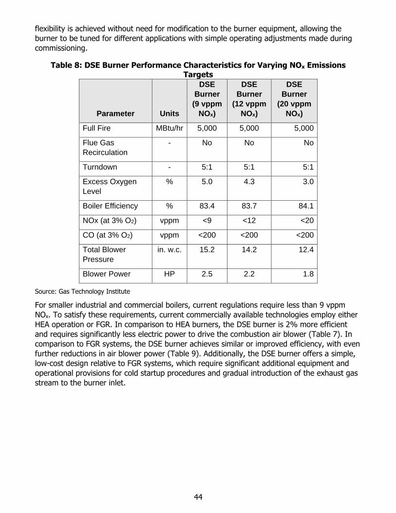
44
flexibility is achieved without need for modification to the burner equipment, allowing the
burner to be tuned for different applications with simple operating adjustments made during
commissioning.
Table 8: DSE Burner Performance Characteristics for Varying NOx Emissions Targets
Parameter Units
DSE
Burner
(9 vppm
NOx)
DSE
Burner
(12 vppm
NOx)
DSE
Burner
(20 vppm
NOx)
Full Fire MBtu/hr 5,000 5,000 5,000
Flue Gas
Recirculation
- No No No
Turndown - 5:1 5:1 5:1
Excess Oxygen
Level
% 5.0 4.3 3.0
Boiler Efficiency % 83.4 83.7 84.1
NOx (at 3% O2) vppm <9 <12 <20
CO (at 3% O2) vppm <200 <200 <200
Total Blower
Pressure
in. w.c. 15.2 14.2 12.4
Blower Power HP 2.5 2.2 1.8
Source: Gas Technology Institute
For smaller industrial and commercial boilers, current regulations require less than 9 vppm
NOx. To satisfy these requirements, current commercially available technologies employ either
HEA operation or FGR. In comparison to HEA burners, the DSE burner is 2% more efficient
and requires significantly less electric power to drive the combustion air blower (Table 7). In
comparison to FGR systems, the DSE burner achieves similar or improved efficiency, with even
further reductions in air blower power (Table 9). Additionally, the DSE burner offers a simple,
low-cost design relative to FGR systems, which require significant additional equipment and
operational provisions for cold startup procedures and gradual introduction of the exhaust gas
stream to the burner inlet.
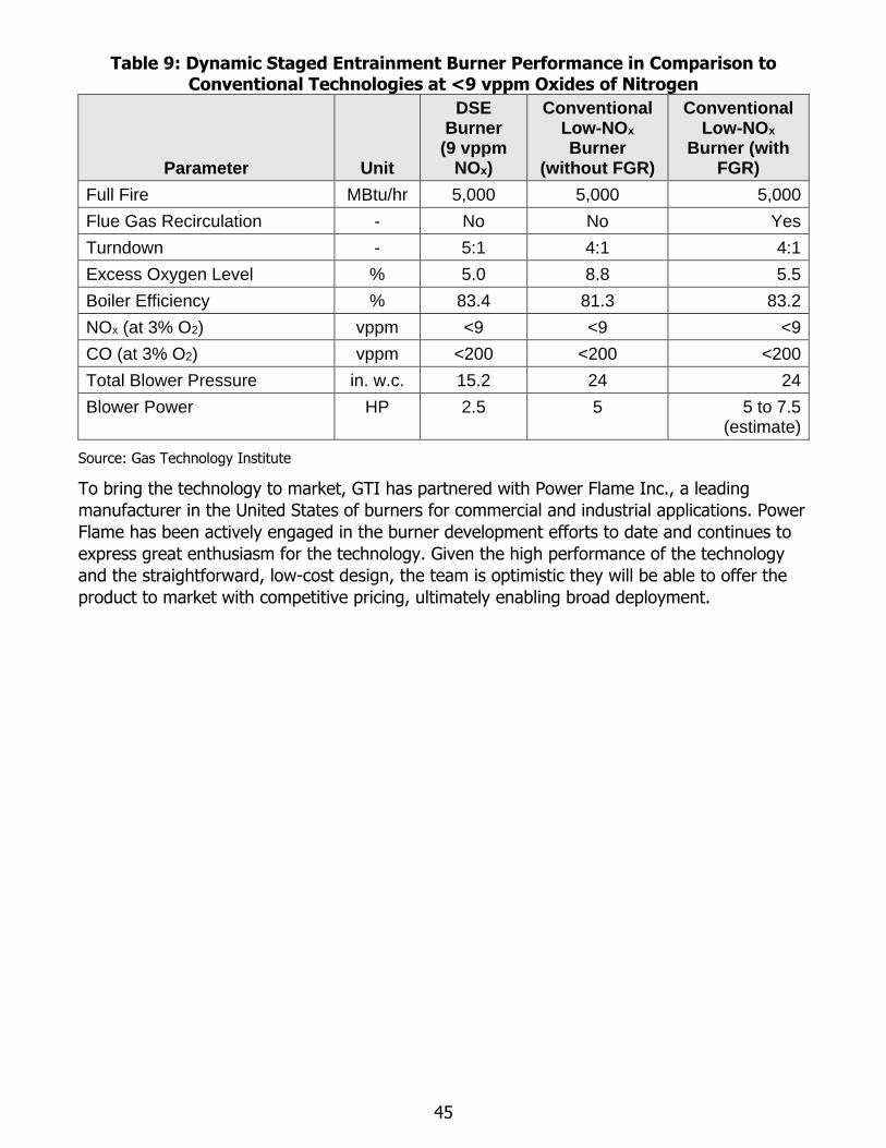
45
Table 9: Dynamic Staged Entrainment Burner Performance in Comparison to Conventional Technologies at <9 vppm Oxides of Nitrogen
Parameter Unit
DSE Burner
(9 vppm NOx)
Conventional Low-NOx Burner
(without FGR)
Conventional Low-NOx
Burner (with FGR)
Full Fire MBtu/hr 5,000 5,000 5,000
Flue Gas Recirculation - No No Yes
Turndown - 5:1 4:1 4:1
Excess Oxygen Level % 5.0 8.8 5.5
Boiler Efficiency % 83.4 81.3 83.2
NOx (at 3% O2) vppm <9 <9 <9
CO (at 3% O2) vppm <200 <200 <200
Total Blower Pressure in. w.c. 15.2 24 24
Blower Power HP 2.5 5 5 to 7.5 (estimate)
Source: Gas Technology Institute
To bring the technology to market, GTI has partnered with Power Flame Inc., a leading
manufacturer in the United States of burners for commercial and industrial applications. Power
Flame has been actively engaged in the burner development efforts to date and continues to
express great enthusiasm for the technology. Given the high performance of the technology
and the straightforward, low-cost design, the team is optimistic they will be able to offer the
product to market with competitive pricing, ultimately enabling broad deployment.
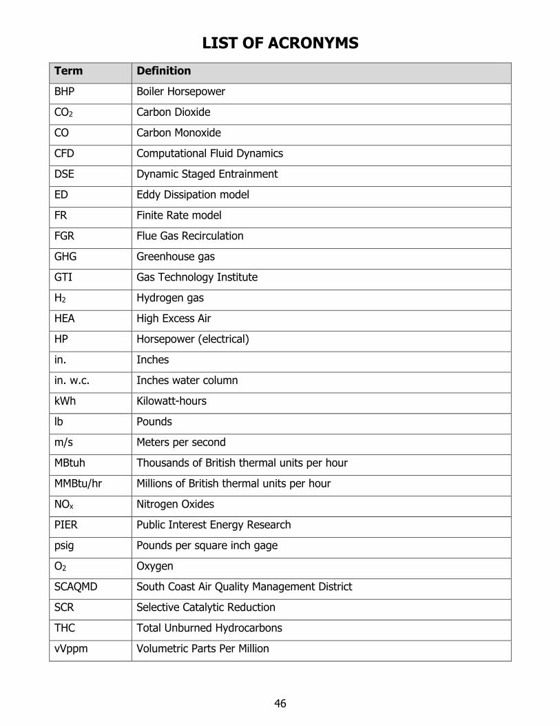
46
LIST OF ACRONYMS
Term Definition
BHP Boiler Horsepower
CO2 Carbon Dioxide
CO Carbon Monoxide
CFD Computational Fluid Dynamics
DSE Dynamic Staged Entrainment
ED Eddy Dissipation model
FR Finite Rate model
FGR Flue Gas Recirculation
GHG Greenhouse gas
GTI Gas Technology Institute
H2 Hydrogen gas
HEA High Excess Air
HP Horsepower (electrical)
in. Inches
in. w.c. Inches water column
kWh Kilowatt-hours
lb Pounds
m/s Meters per second
MBtuh Thousands of British thermal units per hour
MMBtu/hr Millions of British thermal units per hour
NOx Nitrogen Oxides
PIER Public Interest Energy Research
psig Pounds per square inch gage
O2 Oxygen
SCAQMD South Coast Air Quality Management District
SCR Selective Catalytic Reduction
THC Total Unburned Hydrocarbons
vVppm Volumetric Parts Per Million
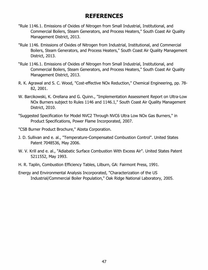
47
REFERENCES
"Rule 1146.1. Emissions of Oxides of Nitrogen from Small Industrial, Institutional, and
Commercial Boilers, Steam Generators, and Process Heaters," South Coast Air Quality
Management District, 2013.
"Rule 1146. Emissions of Oxides of Nitrogen from Industrial, Institutional, and Commercial
Boilers, Steam Generators, and Process Heaters," South Coast Air Quality Management
District, 2013.
“Rule 1146.1. Emissions of Oxides of Nitrogen from Small Industrial, Institutional, and
Commercial Boilers, Steam Generators, and Process Heaters," South Coast Air Quality
Management District, 2013.
R. K. Agrawal and S. C. Wood, "Cost-effective NOx Reduction," Chemical Engineering, pp. 78-
82, 2001.
W. Barcikowski, K. Orellana and G. Quinn., "Implementation Assessment Report on Ultra-Low
NOx Burners subject to Rules 1146 and 1146.1," South Coast Air Quality Management
District, 2010.
"Suggested Specification for Model NVC2 Through NVC6 Ultra Low NOx Gas Burners," in
Product Specifications, Power Flame Incorporated, 2007.
"CSB Burner Product Brochure," Alzeta Corporation.
J. D. Sullivan and e. al., "Temperature-Compensated Combustion Control". United States
Patent 7048536, May 2006.
W. V. Krill and e. al., "Adiabatic Surface Combustion With Excess Air". United States Patent
5211552, May 1993.
H. R. Taplin, Combustion Efficiency Tables, Lilburn, GA: Fairmont Press, 1991.
Energy and Environmental Analysis Incorporated, "Characterization of the US
Industrial/Commercial Boiler Population," Oak Ridge National Laboratory, 2005.


![How to reduce emission of nitrogen oxides [NOx] from](https://img.pdfslide.us/doc/110x75/616a4dd111a7b741a35108dc/how-to-reduce-emission-of-nitrogen-oxides-nox-from-.jpg)