Embed Size (px)
DESCRIPTION
DAT Tape Commisioning Dn9815934x3x0xen
Citation preview
GER4 version 3
Commissioning of DAT Tape Unit
Commissioning and Integration Manual2.2DGER4_2PD
DN9815934 © Nokia Corporation 1 (24)Issue 3-0 en Nokia Proprietary and Confidential
Commissioning of DAT Tape Unit
The information in this documentation is subject to change without notice and describes onlythe product defined in the introduction of this documentation. This documentation is intendedfor the use of Nokia's customers only for the purposes of the agreement under which thedocumentation is submitted, and no part of it may be reproduced or transmitted in any form ormeans without the prior written permission of Nokia. The documentation has been prepared tobe used by professional and properly trained personnel, and the customer assumes fullresponsibility when using it. Nokia welcomes customer comments as part of the process ofcontinuous development and improvement of the documentation.
The information or statements given in this documentation concerning the suitability, capacity,or performance of the mentioned hardware or software products cannot be considered bindingbut shall be defined in the agreement made between Nokia and the customer. However, Nokiahas made all reasonable efforts to ensure that the instructions contained in the documentationare adequate and free of material errors and omissions. Nokia will, if necessary, explain issueswhich may not be covered by the documentation.
Nokia's liability for any errors in the documentation is limited to the documentary correction oferrors. NOKIA WILL NOT BE RESPONSIBLE IN ANY EVENT FOR ERRORS IN THISDOCUMENTATION OR FOR ANY DAMAGES, INCIDENTAL OR CONSEQUENTIAL(INCLUDING MONETARY LOSSES), that might arise from the use of this documentation orthe information in it.
This documentation and the product it describes are considered protected by copyrightaccording to the applicable laws.
NOKIA logo is a registered trademark of Nokia Corporation.
Other product names mentioned in this documentation may be trademarks of their respectivecompanies, and they are mentioned for identification purposes only.
Copyright © Nokia Corporation 1999. All rights reserved.
DX 200 is a registered trademark of Nokia Telecommunications Oy
2 (24) © Nokia Corporation DN9815934Nokia Proprietary and Confidential Issue 3-0en
Contents
Contents 3
List of tables 4
List of figures 5
Summary of changes 7
1 Introduction 9
2 Principle 11
3 Accessories 13
4 Installation 15
5 Commissioning the DAT tape unit after installation 17
6 Settings and strappings in DAT tape unit 196.1 Settings and Strappings of HP Tapes 196.2 Jumper and Switch Settings of Sony SDT-9000 Tape 22
DN9815934 © Nokia Corporation 3 (24)Issue 3-0 en Nokia Proprietary and Confidential
Commissioning of DAT Tape Unit
List of tables
Table 1. Index of DAT tape unit 11
Table 2. Strappings in WDDC cartridges 15
Table 3. Description of HP tape settings 20
Table 4. Description of strappings in strapping group W1 for HP Tapes 21
Table 5. Description of Sony SDT-9000 tape settings 23
Table 6. Description of strappings in strapping group W1 for Sony SDT-9000 23
4 (24) © Nokia Corporation DN9815934Nokia Proprietary and Confidential Issue 3-0en
List of figures
Figure 1. Settings and strappings of the HP DAT tape unit 20
Figure 2. Settings and strappings of the Sony DAT tape unit. 22
DN9815934 © Nokia Corporation 5 (24)Issue 3-0 en Nokia Proprietary and Confidential

Commissioning of DAT Tape Unit
6 (24) © Nokia Corporation DN9815934Nokia Proprietary and Confidential Issue 3-0en
Summary of changes
Changes between document issues are cumulative. Therefore, the latest documentissue contains all changes made to previous issues.
Changes made between issues 3 and 2
Basic improvement of document class 2.2. Many terms clarified in the text.
Changes made between issues 2 and 1
INSTALLATION- The old term DDAD has been replaced by the new termCTAD.
SETTINGS AND STRAPPINGS IN DAT TAPE UNIT- Added HP C1554A.Clarified figure Fig.1. Added a whole section on Sony SDT-9000 tape jumper andswitch settings.
DN9815934 © Nokia Corporation 7 (24)Issue 3-0 en Nokia Proprietary and Confidential

Commissioning of DAT Tape Unit
8 (24) © Nokia Corporation DN9815934Nokia Proprietary and Confidential Issue 3-0en
Introduction
1 IntroductionThis manual lists the installation accessories and provides a brief description ofthe connection of the DAT tape unit (briefly tape unit) to a cartridge-based DX200 exchange.
DN9815934 © Nokia Corporation 9 (24)Issue 3-0 en Nokia Proprietary and Confidential

Commissioning of DAT Tape Unit
10 (24) © Nokia Corporation DN9815934Nokia Proprietary and Confidential Issue 3-0en
Principle
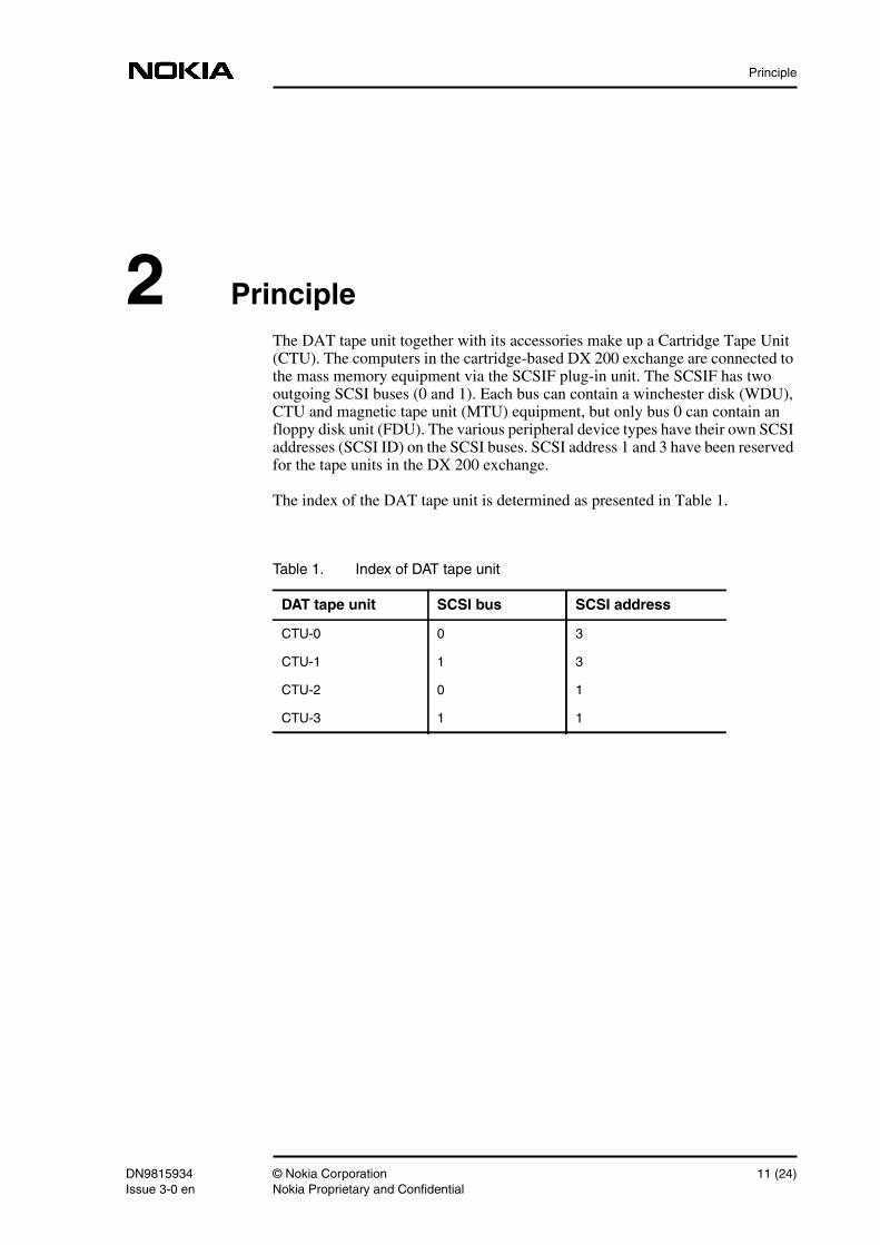
2 PrincipleThe DAT tape unit together with its accessories make up a Cartridge Tape Unit(CTU). The computers in the cartridge-based DX 200 exchange are connected tothe mass memory equipment via the SCSIF plug-in unit. The SCSIF has twooutgoing SCSI buses (0 and 1). Each bus can contain a winchester disk (WDU),CTU and magnetic tape unit (MTU) equipment, but only bus 0 can contain anfloppy disk unit (FDU). The various peripheral device types have their own SCSIaddresses (SCSI ID) on the SCSI buses. SCSI address 1 and 3 have been reservedfor the tape units in the DX 200 exchange.
The index of the DAT tape unit is determined as presented in Table 1.
Table 1. Index of DAT tape unit
DAT tape unit SCSI bus SCSI address
CTU-0 0 3
CTU-1 1 3
CTU-2 0 1
CTU-3 1 1
DN9815934 © Nokia Corporation 11 (24)Issue 3-0 en Nokia Proprietary and Confidential

Commissioning of DAT Tape Unit
12 (24) © Nokia Corporation DN9815934Nokia Proprietary and Confidential Issue 3-0en
Accessories
3 AccessoriesThe following accessories are needed to install the DAT tape unit:
• DAT tape unit
• DAT tape (DDS-type)
• cleaning cassette
• plug-in unit DDAD or CTAD, one for each tape unit (attachment adapter)
• cartridge WDDC, one for two tape units
• plug-in unit SCSIT-S, two for each SCSI bus (terminal resistor)
• power supply PSC4, one for each tape unit
• SCSI bus cable
• power supply cable for WDDC cartridge, one for each power supply unit.
DN9815934 © Nokia Corporation 13 (24)Issue 3-0 en Nokia Proprietary and Confidential
Commissioning of DAT Tape Unit
14 (24) © Nokia Corporation DN9815934Nokia Proprietary and Confidential Issue 3-0en
Installation
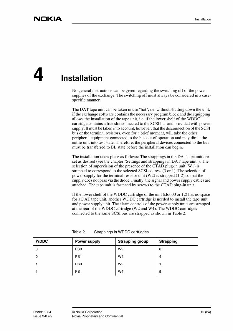
4 InstallationNo general instructions can be given regarding the switching off of the powersupplies of the exchange. The switching off must always be considered in a case-specific manner.
The DAT tape unit can be taken in use "hot", i.e. without shutting down the unit,if the exchange software contains the necessary program block and the equippingallows the installation of the tape unit, i.e. if the lower shelf of the WDDCcartridge contains a free slot connected to the SCSI bus and provided with powersupply. It must be taken into account, however, that the disconnection of the SCSIbus or the terminal resistors, even for a brief moment, will take the otherperipheral equipment connected to the bus out of operation and may direct theentire unit into test state. Therefore, the peripheral devices connected to the busmust be transferred to BL state before the installation can begin.
The installation takes place as follows: The strappings in the DAT tape unit areset as desired (see the chapter "Settings and strappings in DAT tape unit"). Theselection of supervision of the presence of the CTAD plug-in unit (W1) isstrapped to correspond to the selected SCSI address (3 or 1). The selection ofpower supply for the terminal resistor unit (W2) is strapped (1-2) so that thesupply does not pass via the diode. Finally, the signal and power supply cables areattached. The tape unit is fastened by screws to the CTAD plug-in unit.
If the lower shelf of the WDDC cartridge of the unit (slot 00 or 12) has no spacefor a DAT tape unit, another WDDC cartridge is needed to install the tape unitand power supply unit. The alarm controls of the power supply units are strappedat the rear of the WDDC cartridge (W2 and W4). The WDDC cartridgesconnected to the same SCSI bus are strapped as shown in Table 2.
Table 2. Strappings in WDDC cartridges
WDDC Power supply Strapping group Strapping
0 PS0 W2 0
0 PS1 W4 4
1 PS0 W2 1
1 PS1 W4 5
DN9815934 © Nokia Corporation 15 (24)Issue 3-0 en Nokia Proprietary and Confidential
Commissioning of DAT Tape Unit
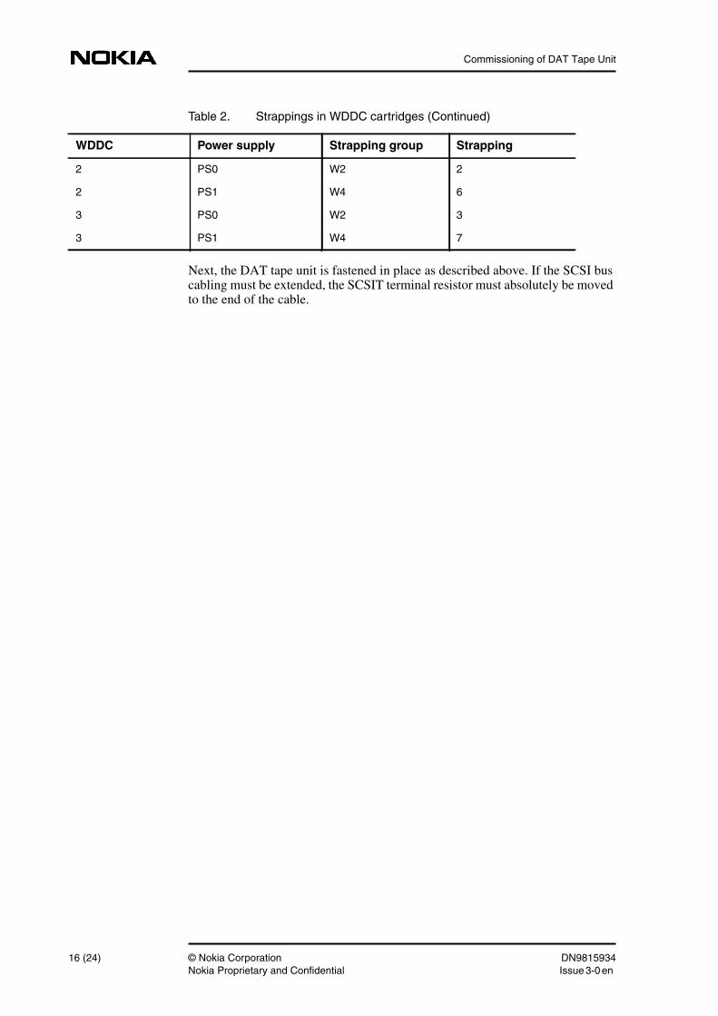
Next, the DAT tape unit is fastened in place as described above. If the SCSI buscabling must be extended, the SCSIT terminal resistor must absolutely be movedto the end of the cable.
2 PS0 W2 2
2 PS1 W4 6
3 PS0 W2 3
3 PS1 W4 7
Table 2. Strappings in WDDC cartridges (Continued)
WDDC Power supply Strapping group Strapping
16 (24) © Nokia Corporation DN9815934Nokia Proprietary and Confidential Issue 3-0en
Commissioning the DAT tape unit after installation
5 Commissioning the DAT tape unit afterinstallation
When the unit has entered the WO-EX state after the power supply has beenconnected, the CTU automatically rises to BL-SY state ("no cassette tape").When a cassette tape is inserted in the tape unit (must be a DAT DDS tape), thetape unit enters state WO-ID. The state transition may take about a minute. Thetape unit can be monitored with the ISI or IMD commands.
If the unit does not change states according to the condition, the LED indicatorson the DAT tape unit should be observed. The LEDs should indicate that the tapeunit is in standby state. Also check the cabling and strappings.
Also make sure that the TAPEDR program block has been created, because theforced state transitions made with the ISC command are useless if the state of thetape unit does not change automatically according to the situation.
DN9815934 © Nokia Corporation 17 (24)Issue 3-0 en Nokia Proprietary and Confidential

Commissioning of DAT Tape Unit
18 (24) © Nokia Corporation DN9815934Nokia Proprietary and Confidential Issue 3-0en
Settings and strappings in DAT tape unit
Note
6 Settings and strappings in DAT tape unit
6.1 Settings and Strappings of HP Tapes
The HP DAT tape unit used in the cartridge-based DX 200 exchange is of typeHP 35480A, HP C1533A or HP C1554A (3.5", DAT, SCSI).
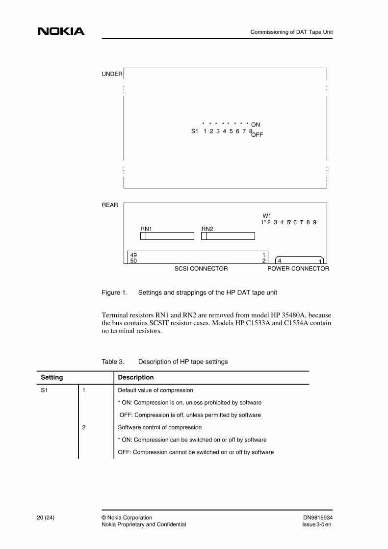
An asterisk (*) in Figure 1 indicates that the strapping or setting is made; in Tables3 and 4 it indicates that the setting is chosen. A question mark (?) indicates thatthe strapping or setting depends on the configuration.
Figure 1 shows the settings made under the HP DAT tape unit and the strappingsin strapping group W1 made at the rear. Table 3 describes the settings and Table4 describes the strappings.
DN9815934 © Nokia Corporation 19 (24)Issue 3-0 en Nokia Proprietary and Confidential
Commissioning of DAT Tape Unit
Figure 1. Settings and strappings of the HP DAT tape unit
Terminal resistors RN1 and RN2 are removed from model HP 35480A, becausethe bus contains SCSIT resistor cases. Models HP C1533A and C1554A containno terminal resistors.
RN1 RN2
SCSI CONNECTOR POWER CONNECTOR
REAR
UNDER
...
S1 1 2 3 4 5 6 7 8ON
OFF
W1
* * * * * * * *
*1 2 3 4 5 6 7 8 9? *
50 2 4 149 1
...
...
...
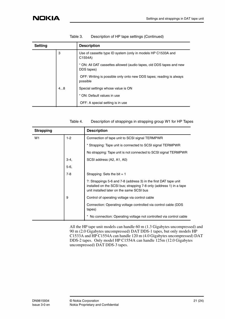
Table 3. Description of HP tape settings
Setting Description
S1 1 Default value of compression
* ON: Compression is on, unless prohibited by software
OFF: Compression is off, unless permitted by software
2 Software control of compression
* ON: Compression can be switched on or off by software
OFF: Compression cannot be switched on or off by software
20 (24) © Nokia Corporation DN9815934Nokia Proprietary and Confidential Issue 3-0en
Settings and strappings in DAT tape unit
All the HP tape unit models can handle 60 m (1.3 Gigabytes uncompressed) and90 m (2.0 Gigabytes uncompressed) DAT DDS-1 tapes, but only models HPC1533A and HP C1554A can handle 120 m (4.0 Gigabytes uncompressed) DATDDS-2 tapes. Only model HP C1554A can handle 125m (12.0 Gigabytesuncompressed) DAT DDS-3 tapes.
3 Use of cassette type ID system (only in models HP C1533A andC1554A)
* ON: All DAT cassettes allowed (audio tapes, old DDS tapes and newDDS tapes)
OFF: Writing is possible only onto new DDS tapes; reading is alwayspossible
4...8 Special settings whose value is ON
* ON: Default values in use
OFF: A special setting is in use
Table 3. Description of HP tape settings (Continued)
Setting Description
Table 4. Description of strappings in strapping group W1 for HP Tapes
Strapping Description
W1 1-2 Connection of tape unit to SCSI signal TERMPWR
* Strapping: Tape unit is connected to SCSI signal TERMPWR
No strapping: Tape unit is not connected to SCSI signal TERMPWR
3-4, SCSI address (A2, A1, A0)
5-6,
7-8 Strapping: Sets the bit = 1
?: Strappings 5-6 and 7-8 (address 3) in the first DAT tape unitinstalled on the SCSI bus; strapping 7-8 only (address 1) in a tapeunit installed later on the same SCSI bus
9 Control of operating voltage via control cable
Connection: Operating voltage controlled via control cable (DDStapes)
* No connection: Operating voltage not controlled via control cable
DN9815934 © Nokia Corporation 21 (24)Issue 3-0 en Nokia Proprietary and Confidential
Commissioning of DAT Tape Unit
Note
6.2 Jumper and Switch Settings of Sony SDT-9000Tape
The Sony DAT tape unit used in the cartridge-based DX 200 exchange is of typeSony SDT-9000 (DDS-3, 12 GB) DAT-Drive.
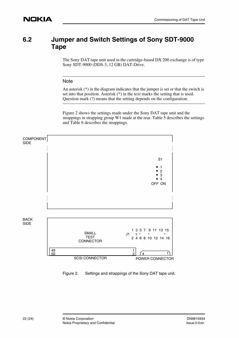
An asterisk (*) in the diagram indicates that the jumper is set or that the switch isset into that position. Asterisk (*) in the text marks the setting that is used.Question mark (?) means that the setting depends on the configuration.
Figure 2 shows the settings made under the Sony DAT tape unit and thestrappings in strapping group W1 made at the rear. Table 5 describes the settingsand Table 6 describes the strappings.
Figure 2. Settings and strappings of the Sony DAT tape unit.
SCSI CONNECTOR POWER CONNECTOR
BACKSIDE
COMPONENTSIDE
...
S1
1 2 3 4
ONOFF
J1 *1 3 5 7 9 11 13 15
2 4 6 8 10 12 14 16? *
50 2 4 149 1
...
...
...
*SMALLTEST
CONNECTOR
22 (24) © Nokia Corporation DN9815934Nokia Proprietary and Confidential Issue 3-0en
Settings and strappings in DAT tape unit
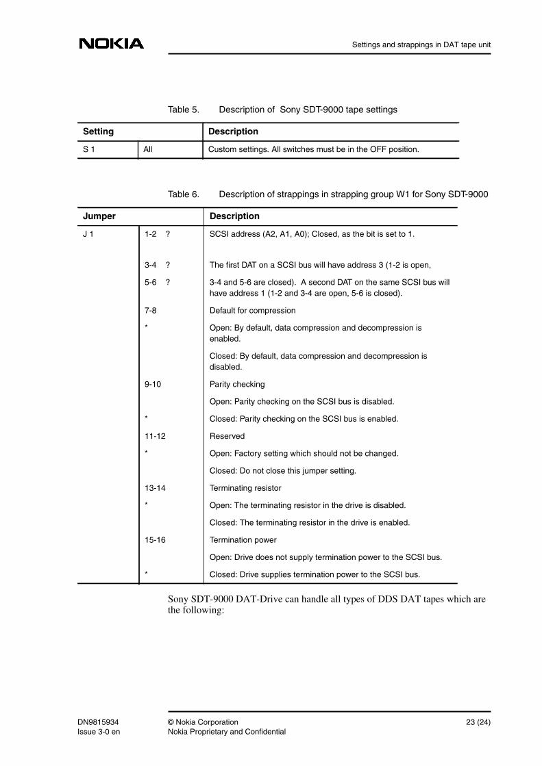
Sony SDT-9000 DAT-Drive can handle all types of DDS DAT tapes which arethe following:
Table 5. Description of Sony SDT-9000 tape settings
Setting Description
S 1 All Custom settings. All switches must be in the OFF position.
Table 6. Description of strappings in strapping group W1 for Sony SDT-9000
Jumper Description
J 1 1-2 ? SCSI address (A2, A1, A0); Closed, as the bit is set to 1.
3-4 ? The first DAT on a SCSI bus will have address 3 (1-2 is open,
5-6 ? 3-4 and 5-6 are closed). A second DAT on the same SCSI bus willhave address 1 (1-2 and 3-4 are open, 5-6 is closed).
7-8 Default for compression
* Open: By default, data compression and decompression isenabled.
Closed: By default, data compression and decompression isdisabled.
9-10 Parity checking
Open: Parity checking on the SCSI bus is disabled.
* Closed: Parity checking on the SCSI bus is enabled.
11-12 Reserved
* Open: Factory setting which should not be changed.
Closed: Do not close this jumper setting.
13-14 Terminating resistor
* Open: The terminating resistor in the drive is disabled.
Closed: The terminating resistor in the drive is enabled.
15-16 Termination power
Open: Drive does not supply termination power to the SCSI bus.
* Closed: Drive supplies termination power to the SCSI bus.
DN9815934 © Nokia Corporation 23 (24)Issue 3-0 en Nokia Proprietary and Confidential
Commissioning of DAT Tape Unit
• 60 m DDS-1 (1,3 GB uncompressed); this tape type is not recommended
• 90 m DDS-1 (2,0 GB uncompressed)
• 120 m DDS-2 (4,0 GB uncompressed)
• 125 m DDS-3 (12,0 GB uncompressed)
24 (24) © Nokia Corporation DN9815934Nokia Proprietary and Confidential Issue 3-0en