Embed Size (px)
Citation preview

DAIRY AIR WIND
GENERATION PROJECT
SYSTEM IMPACT STUDY
2200KW
Crocket Engineering, LLC ·
August, 2016
Exhibit DAW-DPE-3 Page 1 of 53
Table of Contents
Page
1) Project Overview ................................................... 3
2) System Description ................................................ 4
3) Analysis Criteria ..................................................... 5
4) Interconnection Requirements. . . . . . . . . . . . . . . . . . . . . . . . . . . . . . . . . . . 8
5) Summary ............................................................. 12
6) Appendix ............................................................ 13
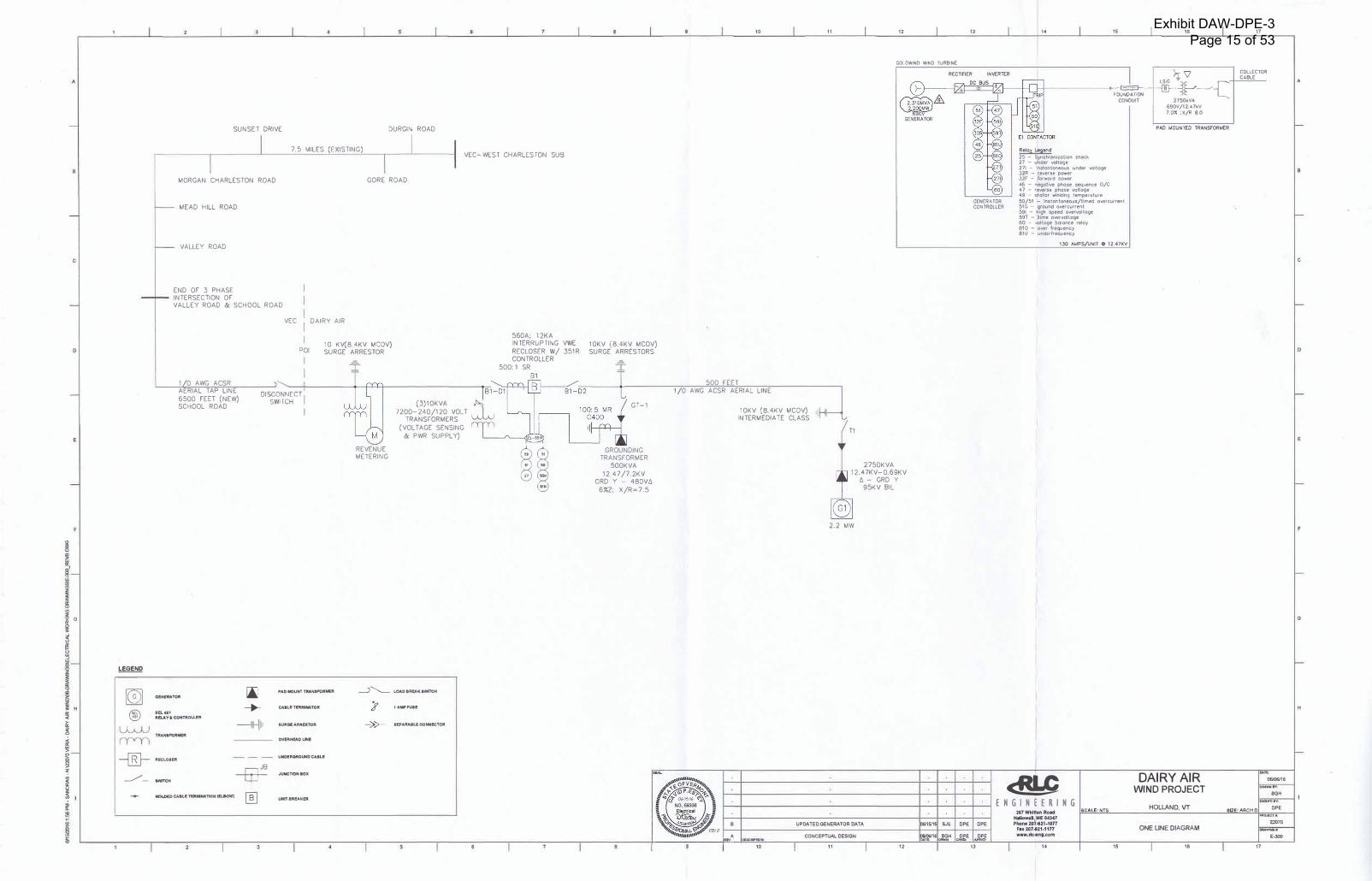
A. System One-line Diagram
B. Project Site Plan
C. Generator and Equipment Specifications
D. Circuit Map
E. PSB Rule 5.500, Section 5.505
F. Substation Load Duration Curve
G.IEEE 1547 2014 Amendment
H. Fast Track Screening
I. Cost Estimate
2
Exhibit DAW-DPE-3 Page 2 of 53
1. Project Overview
Dairy Air Wind, LLC has proposed installing a 2200 kW1
wind turbine system, on School Road in Holland
2, Vermont. The proposed generation will be interconnected
at 12.5GrdY/7.2 kV with a Vermont Electric Cooperative (VEC) distribution system that originates at VEC's West Charleston Substation.
The West Charleston Substation is served via VEC's Newport-Island Pond 46 kV line, which is supplied by Vermont Electric Power Company's (VELCO) 115 kV system.
The proposed generation requires a Certificate of Public Good (CPG) under 30 V.S.A. §248. As required by §248(b) (3) of this statute, the applicant mustdemonstrate that the generation "will not adversely affect system stability andreliability". This System Impact Study will demonstrate that the generator will meetthese requirements for operation, provided that the additional analyses and upgradesspecified in Section 4 are performed and any recommended upgrades and settings areimplemented. This report assumes a maximum net output for the wind turbine of2200 kW. For outputs above this level, additional analysis will be required.
1 Net AC output 2
See Circuit Map, Appendix D
3
Exhibit DAW-DPE-3 Page 3 of 53

2. System Description
The project is presently served via VEC's West Charleston Substation. The substation consists of a 5/5.6/73 MV A, 46-13.2kV transformer, three 328 amp Cooper VR-32 regulators with Form CL-6A controls and four distribution circuits protected by Cooper VWE reclosers with Form 6 controls. The distribution circuits serve portions of Derby, Morgan, Holland, and Island Pond. The project is on the Holland Feeder, l A. In addition, Great Bay Hydro operates a 675 kW hydro plant served from the West Charleston Bus. A 500 kW solar project is proposed for Morgan and will be considered in the report. There are a set of regulators on Mead Hill Road with Form CL-7 A controls.
The distribution line that will be interconnected to the proposed Project is a multigrounded wye circuit. The total length of distribution line between the Substation and the project location is approximately 8.7 miles, consisting of 7.7 miles of#2 ACSR three phase construction and .33 miles of 6A Copperweld, single phase construction. This study assumes that the 6A Copperweld has been replaced with three phase, 4/0 AAAC construction and that the 4/0 AAAC is extended 3000' to the site. The developer has planned a 500' 1/0 AAAC extension to the wind turbine.
The peak load on the circuit is 1235 kW based upon recent peak load readings at the Substation. There is a slight imbalance on the circuit, with A phase loaded to 59 amps and B phase loaded to 55 amps and C phase loaded to 61 amps.
There are 300 kV Ars of capacitors on this circuit as follows:
Location
Mead Hill Road
Phase kV Ar/Phase Total
ABC 100 300
All of the capacitors are fixed on. A review of the V Ar flows calculated by the loadflow analysis indicated that no changes are necessary at this time.
The substation regulators are positioned in a "bus regulation" configuration with cogeneration settings on. It is assumed that the Mead Hill Road regulators will be set to cogeneration mode also.
The new generator step-up transformer has been specified with a nameplate rating of 2750 kV A, 12.5GrdY/7.2 volt wye-690 Delta- 398 grounded wye configuration, and 7 % impedance. In addition, a 500 kV A grounding transformer will be installed at the interconnection.
3 5 MV A nameplate with additional cooling ratings
4
Exhibit DAW-DPE-3 Page 4 of 53

A lockable load-break gang switch, metering and recloser will be installed where the VEC distribution line enters the project property. The load-break switch & recloser are inside the property, as shown on Exhibit B.
5
Exhibit DAW-DPE-3 Page 5 of 53

3. Analysis Criteria and Study Results
The load flow studies were conducted using the MilSoft WindMil distribution circuit analysis program. WindMil was used to perform peak and minimum load level cases and the fault calculations. The peak load case is with the substation at 2540 kW and -100 kV Ar. The minimum load case is with the substation at 1000 kW and -300kV Ar. The circuit is loaded to approximately 1235 kW and 400 kW, respectively. A500 kW solar plant is planned for Morgan and is considered on for this analysis.
The study was conducted under the guidance of the following reports:
• IEEE Standard 154 7, IEEE Standard for Interconnecting DistributedResources with Electric Power Systems, July 28, 2003 and 2014Amendment.4
• PSB Rule 5.500 Interconnection Procedures for Proposed Electric GenerationResources
• Utility Interconnection Guidelines for Distributed Generation Equipment of 1MW or Less Connected to a Radial Distribution System, Philip Barker,January 23, 2006.
Fast Track Screening
PSB Rule 5.5055 provides a list of criteria that allows a project to be processed
without a Feasibility Study, System Impact Study or Facilities Report. To be considered, a project must meet all of the Fast Track Criteria. The Project does not meet criteria 5.505(B) 3, 4, 8 and 10, at a minimum, and is therefore not eligible as a Fast Track application.6
4 See Appendix G
5 See Appendix E
6 See Appendix H
6
Exhibit DAW-DPE-3 Page 6 of 53

Analysis:
i) Analyze the impact of the generation on the area voltage using loadflowanalysis.
IEEE 1547 now allows for system regulation by distributed generators. The proposed generator can provide up to 720 kV Ar to the system. The analysis therefore will include the generator regulating the voltage up to this level ofV Ar output. The voltage set point for the generator was assumed at .98 PU. The Mead Hill Capacitor has been assumed to be changed to a switched capacitor to reduce the voltage during generation periods.
The voltages, calculated by loadflow analysis, are as follows:
VOLTAGE CHANGE SUMMARY Before Dairy
Mead Hill Air Site At Substation Regulators
On peak, no generation 123.4 115.5 120.7
On peak, 2200 kW on at Dairy Air 122.3 120.5 122.1 On peak, 2200 kW on at Dairy Air and 500 kW
122.5 121.7 122.1 at Morgan Solar
Off peak, no generation 123.3 120.5 121.5
Off peak, 2200 kW unit on at Dairy Air 122.6 122.5 123.0
Off peak, 2200 kW on at Dairy Air and 500 kW 122.6 122.5 123.4
at Morgan Solar
As, shown, the voltage on and off peak are all below the 125.0 maximum allowed. In the case with the on-peak load and no generation on, the 300 kV Ar capacitor on Mead Hill switched on due to low voltage.
7
Exhibit DAW-DPE-3 Page 7 of 53

46 kV issue:
With the addition of the 2200 kW wind project onto the West Charleston Substation there exists a possibility of the project remaining energized when a line to ground fault occurs on the 46 kV system supplying the substation. The substation transformer is a 46 kV delta to 12.5 kV wye configuration. As a result, during a transmission line to ground fault, the phase to ground voltage on the unfaulted phases of the 46 kV system could shift to the full phase to phase voltage and the lightning arresters on the unfaulted phases of the 46 kV system could be experiencing 46 kV. The arresters at West Charleston are 54 kV duty cycle arresters, with a 43 kV MCOY (maximum continuous operating voltage) and would ultimately fail if the condition were to persist under these conditions. The "Suggested Guidelines for Anti-Island Screening" tool points to the condition where the DO is matching the load and V Ars and there is a rotating machine in the potential island that is greater than 25% of the total DO on the system. The total DO is 3375 kW and the hydro output is 675 kW, or 20 % of the total, at full output. Under conditions where the hydro output is at or near 100 % but the wind and or solar is not this condition could be met. To protect the 46 kV system from this possibility, a zero sequence over voltage detection system is required to be installed on the 46 kV bus at the VEC West Charleston Substation. The relay would then be set to trip the Holland Feeder (lA) to remove the source of the overvoltage.
Flicker:
Unlike conventional rotating machines, there is no significant inrush current as a result of energizing an inverter. The wind turbine will ramp up to its full output when it turns on. The voltage could sag as a result of the unit tripping. The maximum voltage drop expected under these circumstances is 1.5% for the 30 seconds that it will take the Mead Hill Regulators to adjust the voltage.
Substation Transformer and Regulator Loading:
The substation transformer is rated 7000 KV A while the substation regulators are rated for 7,500 kV A. The peak loading on the substation is 2500 kW and -100 kV Ar. During peak load periods the substation loading will be reducedby the project while the reverse power flow could be increased to -2375 kWduring light load periods. In either case, substation loading is not a problem.
ii) Analyze the impact of the generation on the circuit fault current:
As shown below, with the 2200 kW generator running, the single phase fault current increases to 674 amps at the Project transformer. No protective devices will be above
8
Exhibit DAW-DPE-3 Page 8 of 53

their interrupting rating and the increased fault current will not adversely affect the coordination of any devices. The additional fault current will provide better clearing times for lateral fuses on this section of line which will lower the chances of a minimum current fault remaining energized on the ground.
Fault Current Summary Without With
Generation 2200 kW
Generator
Project 3<J> 535 653
Project 1<j> 577 674
Substation 3<j> 2310 2351
Substation 1 <I> 2659 2697
i) Protection Coordination:
A review of the circuit protection scheme indicated that are no changes necessary as a result of the Project. Fuses may be added to the main line beyond the School Road tap to the project.
ii) Operating Changes:
As a result of the zero sequence detection scheme tripping the Holland Circuit Breaker, VEC personnel will need to be advised to verify that this breaker closes upon restoration of the transmission line.
In addition, IEEE 154 7 recommends items not otherwise discussed.
Section 4.1.17
requires that coordination with and approval of, the area EPS and DRoperators, shall be required for the DR to actively participate to regulate the voltage by changes of real and reactive power. The DR shall not cause the Area EPS service voltage at other Local EPSs to go outside the requirements of ANSI C84.1-2011 1995, Range A. It is recommended that the DR be allowed to actively regulate the voltage.
7 1547 2014 Amendment
9
Exhibit DAW-DPE-3 Page 9 of 53

Section 4.1.2 requires that the generators not disrupt the area grounding nor have an undue effect on ground fault protection of the circuit. Use of a grounded wyegrounded-wye transformer with an ungrounded wye source can lead to neutral shift on the primary system during a ground fault where the line or substation recloser opents. The PCC will include a grounding bank with a tripping function to the PCC recloser for ground faults.
Section 4.1.3 requires that synchronization not cause large voltage fluctuations or flicker issues. Because the generator will be inverter based, no large inrush currents will occur during synchronization, so voltage fluctuations and flicker will not be issues as with induction generators. The impact of the generator under various voltage conditions is described above.
Section 4.1.4 deals with issues associated with interconnection with a secondary spot network. The Project will not be connected to a spot network.
Section 4.1.5 requires that the generators not energize the distribution circuit when the circuit is de-energized. This requirement will be met with relaying at the recloser at the PCC and the use of an overvoltage detection scheme at the West Charleston Substation.
Section 4.1.6 requires that generators above 250 kV A have monitoring provisions to
provide connection status, and real and reactive power output and the voltage at the point of common coupling. The Project plans to install 2200 kW of generation, therefore monitoring provisions will be required. A telemetering package that includes status, real and reactive power output and voltage monitoring, at a minimum, will be required.
Section 4.1. 7 requires the installation of a readily accessible, lockable switch with a visible opening be installed between the Area EPS and the DG unit. Three disconnect switches will be installed in front of the recloser for visible protection. The recloser can be locked out.
Section 4.1.81 requires that the interconnection system shall be capable of withstanding electromagnetic interference in accordance with IEEE standard C37.90.2-1995 without miss operation. The equipment meets this standard.8
Section 4.1.8.2 requires that the system withstand voltage and current surges in accordance with IEEE C62.41.2-2002 or C37.90.l-2002, as applicable. The equipment meets these standards.9
Section 4.1.8.3 requires that the interconnection paralleling device be capable of 220% of the interconnection voltage. The equipment meets this standard. 10
8 Per the manufacturer's literature
9 Per the manufacturer's literature
10 Per the manufacturer's literature
10
Exhibit DAW-DPE-3 Page 10 of 53
Section 4.2.1 requires that the DR unit shall cease to energize the Area EPS for faults on the Area EPS circuit to which is connected. The relays will be set to trip the generator for faults on the distribution system.
Section 4.2.3 requires the generator to trip within specific times when the voltage is outside of preset limits. The generator over voltage and under voltage relays will be set to meet this Standard, as amended in 2014. See Table 1, Appendix G.
Section 4.2.4 requires that the DG shall sense high and low frequency conditions and trip within specified times. The generator under and over frequency relays will be set to meet this Standard, as amended in 2014. See Table 2 in Appendix G.
Section 4.2.6 requires that the DG not reconnect until the distribution system is within the limits specified by Range B of ANSI C84.1-1995 and a frequency range of 59.3-60.5 Hz. The applicable B Range values are 424 to 508 volts. In addition, a time delay for up to five minutes prior to re-energizing shall be included in the generator relaying. The under and over frequency relays and under and over voltage relays will assure that this standard is met. The inverter shall be set to implement the proposed time delay.
Section 4.3.1 requires that the system not inject DC current greater than .5% of the full rated output current at the point of interconnection. The inverter meets this standard. 11
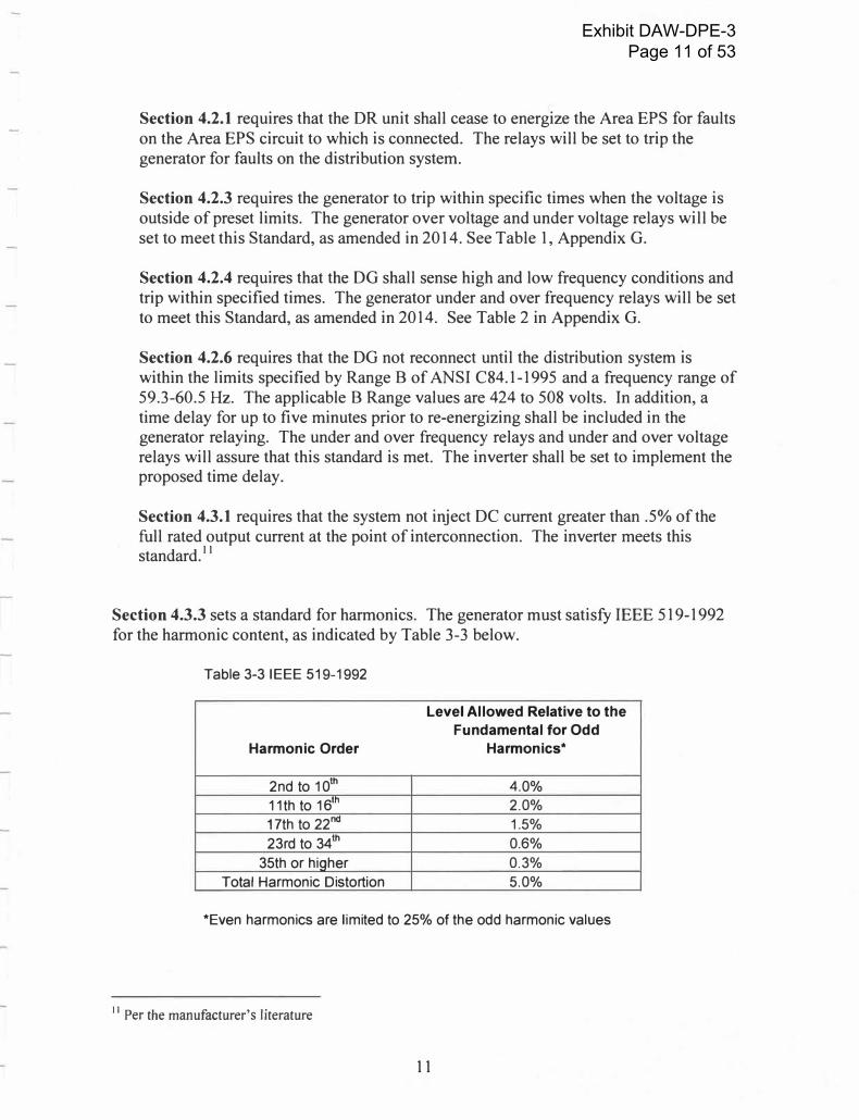
Section 4.3.3 sets a standard for harmonics. The generator must satisfy IEEE 519-1992 for the harmonic content, as indicated by Table 3-3 below.
Table 3-3 IEEE 519-1992
Harmonic Order
2nd to 10th
11th to 16th
17th to 22nd
23rd to 34th
35th or hiQher
Total Harmonic Distortion
Level Allowed Relative to the
Fundamental for Odd
Harmonics*
4.0%
2.0%
1.5%
0.6%
0.3%
5.0%
*Even harmonics are limited to 25% of the odd harmonic values
11 Per the manufacturer's Literature
11
Exhibit DAW-DPE-3 Page 11 of 53
The specifications for this generator limit the total harmonics to less than the required 3%.
Section 4.4.1 requires that the generator not unintentionally island a portion of the distribution circuit and be de-energized within two seconds of a condition that would lead to islandizing. The inverter requires AC input to operate and will sense the loss of incoming power. In addition, the under and over frequency, voltage relays and ground fault detection relay will sense an islanding condition and trip the unit.
Section 4 lists the performance tests required to be conducted to demonstrate that the interconnection meets the requirements laid out in Section 3. The Project will be required to conduct and document the results of these tests prior to normal operation of the units in parallel with the Vermont Electric Cooperative System. The specific test requirements are listed in Appendix F.
12
Exhibit DAW-DPE-3 Page 12 of 53
4. Interconnection Requirements
The following items are required to assure proper operation of the new PV generators at the Project facility.
a. Installation of a grounding bank to provide a grounded generation source to theVEC distribution grid.
b. Installation of a high side voltage ground fault detection relay.
c. Installation of a SCADA controlled and motor operated three phase gang load
break switch at the Point of Interconnection (POI) to provide protection and avisual, lockable open point for line maintenance. SCADA requires a suitablecommunications path for SCADA back to the VEC Control Center.
d. Replacement of the lightning arresters at West Charleston, Island Pond andNewport substations if necessary.
e. Installation of a zero sequence over voltage detection scheme on the 46 kV bus atWest Charleston Substation, set to trip the Holland Feeder recloser.
f. The Project system to be inspected by a State Electrical Inspector to assurecompliance with the National Electrical Code.
g. Cost estimate for VEC's work is in Appendix Ih. The Project will complete the testing required by IEEE 1547.1 2005 and provide a
written copy to VEC.
13
Exhibit DAW-DPE-3 Page 13 of 53
APPENDIX A
System One-Line Diagram
14
Exhibit DAW-DPE-3 Page 14 of 53
ie G
� � g
;!: H 0: < i:: iii
�
I � !
LEGEND ---
� ®
SUNSET DRIVE DURGIN ROAD
7.5 MILES {EXISTING) VEC-WEST CHARLESTON SUB
MORGAN CHARLESTON ROAD
MEAD HILL ROAD
VALLEY ROAD
END OF 3 PHASE INTERSECTION OF VALLEY ROAD & SCHOOL ROAD
GORE ROAD
VEC : DAIRY AIR
1/0 AWG ACSR AERIAL TAP LINE 6500 FEET (NEW) SCHOOL ROAD
POI I
I
oisi����cT
II
10 KV(B.4KV MCOV) SURGE ARRESTOR
T
REVENUE METERING
(3)10KVA �
· 7200-240/120 VOLT
TRANSFORMERS (VOLTAGE SENSING
& PWR SUPPLY)
r.i _..,_
PAO MOUNT TMNSFORMER �'--- LOADIIIU!AKIWm:::H OENEMTOIII
CAIL! TERMINA TOil SEL411
% 1AMPFUSI!
111!1.AY lo CONTROUD:
---lf--111 IUIIICM!AfUlEST0R � >- 19ARABL£ CONNl!CTOIII
TRANll'OIIMER OVl!RHl!AD UNI!
560A; 12KA INTERRUPTING VWE RECLOSER W/ 351R CONTROLLER
500: 1 SR
�;' "' .,."'
-[ID-- IIIECLOSEII
T UNDflllQftOUNO CABLE
___,,/_ IWITCH
JUNCTION BOX
M0l.OEDCAILETOMINAT10NIIEL80Wl [fil Ulfflllft!MCBI
10KV (B.4KV MCOV) SURGE ARRESTORS
T
GT-1
GROUNDING TRANSFORMER
500KVA 12.47 /7.2KV
GRD Y - 4BOVCI 6%Z; X/R=7.5
10 11 12 13 14 15 16 17
GOLOWINO WIND TURBINE
RECTIFIER INVERTER >:c v' COLLECTOR CABLE
500 FEET 1/0 AWG ACSR AERIAL LINE
10KV (8.4KV MCOV) 1il.J INTERMEDIATE CLASS ,'
T1
2750KVA 12.47KV-0.69KV
t, - GRD Y 95KV BIL
2.2 MW
UPDATED GENERATOR DATA
M"t.A CONCEPTUAL DESIGN
10 11 12
06115116 SJS OPE
0&'06/16 BGH �,E '"" -·
GENERATOR
CONTROLLER
LS!G "" ·
F��;;-��t,;;;; +-®- -��- �-c CONDUIT I 2750kVA
Relay Legend
25 - Synchronization check 27 - under volloi;e 271 - nstontoneous under voltage J2R - reverse power 32F - forward power 46 - negative phase sequence 0/C 47 - reverse phase volta�e 49 - stator winding temperature 50/51 - instantaneous/timed ovcrcurrent 51 G - wound overcurrent 591 - t'iigh speed overvottoge 59T - time ovcrvoltoge 60 - >JO!toge balance relay 810 - over frequency 81U - undcrfrequency
130 AI.APS�NIT O 12.47KV
cR!-C
690V/12.47kV 7.0% ;X/R 8.0
PAO l.40UNTEO TRANSf'0Rl.4ER
DAIRY AIR WIND PROJECT
ENGINEERING
06/ll6/16 OAA-ff.
BGH DIOIN"D•�
217WtilltenRoad SCALE: NTS HOLLAND, VT
812E:ARCHO OPE
twfowd,IME 04347 ...,.a•
OPE Phone 207-121.1077 22070 Fax 207-821-1177 ONE LINE DIAGRAM OMWIHGtl:
OPE Al'IWI):
www.l'tc4ng.com E.JOO
13 14 15 16 17
A
C
G
Exhibit DAW-DPE-3 Page 15 of 53

APPENDIXB
Project Site Plan
15
Exhibit DAW-DPE-3 Page 16 of 53

0 0 N 1,-
0 0 N
en
;:o z en
DJ ;:o
;:o
/1�llli:1!
. ;l,,i21t,
1300
1300
. .
.
.
.
�
.�
� �
0 0 '<:I' ,..,
�
� �
Sources: Esri, HE-R'E-;-�·t..0�, lntefmap, incrementf/ Corp}, GEBCO, USGS, FAO, NPS, NRCAN, GeoBase, IGN, Kadaster NL, Ordnance Survey, E�ali'a,�ETI, Esri China (,1-j@l'l'g�Kong), swiss to po, Mapmylndi a, © OpenStreetMap contributors, and the GIS User Communi ty '-".
72°
0w
Dairy Air Wind, LLC Conceptual Site Plan
Topographic map of proposed project area including proposed study area, sit
design, property boundaries, and relate existing interconnection infrastructure.
CANADA
� 1,-.r�--"\.
--¼ r·- .' c:r- -onand
'-., '"-;.,
l
- ..{_
Legend
:Ii Wind Turbine Location
• Point of Interconnection
• • • • UG Collection System
�Upgraded VEC Single Phase Distributic
�New Three Phase Distribution
Crane Pad
Access Road
- VEC Three Phase Distribution
5 ft. Contours, NED DEM
C:=J Property Parcels
0 500 1,000
Feet
2,00(
Data sources: The underlying topographic map an, elevation and VEC electrical data are provided by VCGI at VCGl.vermont.gov. Project data provided VERA Renewables, Inc.
Prepared: 20160613rd
N
A Renewables
Exhibit DAW-DPE-3 Page 17 of 53

APPENDIXC
Generator Specifications
16
Exhibit DAW-DPE-3 Page 18 of 53

Rev.:B-LM DocumentNo.:GW-07FA.0096
GOLDWIND
Goldwind 2.2 MW Turbine General Technical Description
Goldwind Science & Technology Co., ltd.
www.goldwind.com.cn
Exhibit DAW-DPE-3 Page 19 of 53

�GOLDWIND Rev .:B-LM Document No .: GW -O?FA .0096
CONTENTS
1 Scope .. ..... ........... ................. .. ...... ........ .. . ... . . . . . . .. .. . ... . ... .. . 2
2 General Description . . . . . . . . . . . . . . . . . . . . . . . . . . . . . . . . . . . . . . . . . . . . . . . . . . . . . . . . . . . . . . . . . . 2
3 Rotor ....... .. . . ...... .. .. .. . ... .... .... .. .... .... .. ... ...................... ....... 4
4 P MDD Generator . . . . . . . . . . . . . . . . . . . . . . . . . . . . . . . . . . . . . . . . . . . . . . . . . . . . . . . . . . . . . . . . . . . . 6
5 Nacelle. ........................... ......... .. . . . . . .. . . .......... .................. 9
6 Tower . ... . ....................... ................................ ................. ..... .. 11
7 Foundation ...... . .. . ... . .. . . ...... . . .. . . . . . ..... ................ ... .... ..... . . . . . . 11
8 Electrical Systems . . . . . . . . . . . . . . . . . . . . . . . . . . . . . . . . . . . . . . . . . . . . . . . . . . . . . . . . . . . . . . . . . . 11
9 Turbine Controller. . . . . . . . . . . . . . . . . . . . . . . . . . . . . . . . . . . . . . . . . . . . . . . . . . . . . . . . . . . . . . . . . . . 13
10 SCADA (Supervisory Control and Data Acquisition). . . . . . . . . . . . . . . . . . . . . . . . . . . . . . . . . . . . . 14
11 Goldwind 121-2.2MW Wind Turbine Technical Data ................ .... ............... . . 14
Figures
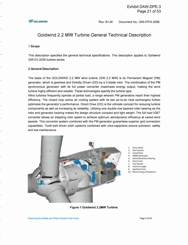
Figure 1 Goldwind 2.2MW Turbine ........................................................................................................ 2
Figure 2 Pitch system and rotor ............................................................................................................. 4
Figure 3 Pitch Control Electrical Diagram ............................................................................................. 5
Figure 4 P MDD Generator ..................................................................................................................... 6
Figure 5 Heat Exchanger ............................................................................................................................ 8
Figure 6 Airflow though the generator ................................................................................................. 9
Figure 7 Yaw System ............................................................................................................................ 10
Figure 8 GW 2.2MW Electrical Diagram ............................................................................................. 12
Figure 9 GW 2.2MW Main Controller Diagram .................................................................................... 13
Tables
Table 1 Goldwind 121-2.2MW Wind Turbine Technical Data ............................................................... 14
Preserving Blue Skies and White Clouds for the Future Page 1 of 14
Exhibit DAW-DPE-3 Page 20 of 53
f;f:GOLOWINO Rev.:B-LM Document No.: GW-O?FA.0096
Goldwind 2.2 MW Turbine General Technical Description
1 Scope
This description specifies the general technical specifications. This description applies to Goldwind
GW121-2200 turbine series.
2 General Description
The basis of the GOLDWIND 2.2 MW wind turbine (GW 2.2 MW) is its Permanent Magnet (PM)
generator, which is gearless and Directly Driven (DD) by a 3-blade rotor. The combination of the PM
synchronous generator with its full power converter maximizes energy output, making the wind
turbine highly efficient and reliable. These technologies specify the turbine type.
Wind turbines frequently operate at partial load; a range wherein PM generators reach their highest
efficiency. The closed loop active air cooling system with its two air-to-air heat exchangers further
optimizes the generator's performance. Direct Drive (DD) is the ultimate concept for reducing turbine
components as well as increasing its reliability. Utilizing one double-row tapered roller bearing as the
rotor and generator bearing makes the design structure compact and light weight. The full load IGBT
converter allows an adapting rotor speed to achieve optimum aerodynamic efficiency at varied wind
speeds. This converter system c.ombined with the PM generator guarantees superior grid connection
capabilities. Tooth-belt driven pitch systems combined with ultra-capacitors ensure precision, safety
and low maintenance.
Figure 1 Goldwind 2.2MW Turbine
Preserving Blue Skies and White Clouds for the Future
1. Rotor Blade 2. Pitch Sys tern 3. casted Hub 4. PMDD Generator 5. Rotor/Generator Bearing 6. Base Frame 7. YawSystem 8. Heat Exchanger 9. Auxiliary Crane 10. Meteorological Equipment
Page 2 of 14
Exhibit DAW-DPE-3 Page 21 of 53
�GOLDWIND Rev.:B-LM Document No.: GW-07FA.0096
Special Features:
• Permanent Magnet "PM" generator
¢ No energy loss through magnetic field excitation
¢ High generator efficiency, especially at partial load
¢ No need for slip rings for excitation of generator-rotor
• Direct Drive "00" multi-pole generator• Direct flange connection between turbine-rotor and generator
¢ Gearless; no gearbox monitoring system
¢ No gearbox oil, no oil pumping, cooling or filtering• One Large Diameter, double-row tapered roller bearing to connect the turbine rotor and
generator rotor unit to generator stator• External generator-rotor concept• Air to air active cooling system
¢ Compact design
¢ Fewer components: high reliability, less maintenance, higher availability
• PMDD generator is combined with full power IGBT converter
¢ Wide range of speed control, optimum turbine-rotor efficiency
¢ Superior grid connection capabilities (ZVRT, LVRT, HVRT)
• Tooth belt driven blade pitch system
¢ No backlash; more precise pitch angle
¢ No grease lubrication needed for the tooth belt
¢ Easy to exchange (compared to a geared pitch bearing)
• Ultra-Capacitors used in series with each pitch actuator motor powersupply
¢ No use of lead-acid battery, no energy loss at low temperature
¢ Long lifetime • No change of operation mode of pitch system during voltage drop or grid loss• Permanent control of energy storage
¢ Safely pitch each blade to a safe position after power loss or for an emergency stop
Version Rated Nominal Rotor
Wind Class Power Diameter
GW121/2200 2.2MW 121m IEC 1118
Preserving Blue Skies and White Clouds for the Future Page 3 of 14
Exhibit DAW-DPE-3 Page 22 of 53

�GOLDWIND Rev.:8-LM Document No.: GW-07FA.0096
3 Rotor
3.1 Blades
The Goldwind 2.2 MW wind turbine rotor is equipped with 3 reinforced fiber glass blades (GRP) that
are produced by qualified international blade manufacturers. The high aerodynamic efficiency of the
rotor is based on the efficient design of the airfoils used in each blade. Different blade lengths are
used depending on the wind class of the site that the turbine will be placed. This optimizes energy
output and loads.
Blade Type Nominal Rotor Actual Rotor Swept Area
Diameter Diameter
LM 58.8 121m 120.lm 11329 m2
3.2 Hub
The hub supports the three rotor blades via the blade bearings and connects them to the generator.
The connections between the blades and hub, as well as the generator-hub connection are flange
bolt connections. The hub is optimized for size and weight and is made of casted iron (EN-GJS-400-
1 BU-LT I GGG 40.3). Additionally, the pitch system, including the pitch motor, gear box, control box,
and the nose cone support structure are integrated into the hub.
3.3 Pitch System
The pitch system is responsible for adjusting the pitch of the three blades. As the blades are pitched,
the angle of attack of each blade is changed, either increasing or decreasing the lift force over the
blades. All three blades are controlled collectively, with each blade acting independently.
The following components and connections are contained in each system.
1. Slew Bearing
2. Pitch Control Cabinet
3. Induction Motor
4. Gear Box
5. Casted Hub
6. Tooth Belt
Figure 2 Pitch system and rotor
Preserving Blue Skies and White Clouds for the Future Page4 of 14
Exhibit DAW-DPE-3 Page 23 of 53

�GOLDWINO Rev.:B-LM Document No.: GW-O?FA.0096
The blade is connected to the hub via a slew bearing. This is a double row ball bearing that allows the
blade to rotate around its longitudinal axis with minimal friction.
Motion is actuated by a 3-phase induction motor. The simple design of induction motors means the
system is reliable with minimal maintenance requirements. The motor is equipped with an
independent cooling fan and a motor brake on the second end.
The output of the motor is connected to a 3-stage planetary gear box.
A reinforced tooth belt transfers the output from the gear box pinion to the outer ring of the blade
bearing. This pre-stressed tooth belt adjusts the pitch angle with superior accuracy and no backlash.
High stiffness composite material ensures minimal elongation over time. The ease of interchanging
belts, and the lack of a need for lubrication, keeps costs at a minimum. The belt system used in the
Goldwind 2.2 MW turbine is a patented technology.
The pitch system receives power from the main power supply in the nacelle by means of a slip ring at
the center of the generator-hub connection. The power is rectified to DC to charge the ultra-capacitor
and power the control circuits. The DC source is thus converted to AC to power the induction motor.
Ll------,
L2---...,
L3
MAIN
CONTROL
�------<I AC
'
'
'-+--+---<I AC
24V 13A
PITCH - - - - - - - - - - - - - - - -, CONTROL - - -- - - -,
24V13A 29V 4.5kW
29V 4.5kW
POSITION SPEED
ENCODER
POSITION SPEED
ENCODER
POSITION SPEED
ENCODER
' I
' .
�-------------- ---------- ----- ---------- ---------------------J
L----------------------------------------------------------------�
Figure 3 Pitch Control Electrical Diagram
The three pitch controllers receive identical signals from the main turbine controller and each blade
subsystem responds independent of the other blades. The independent nature of the system means
that if a single blade fails the other two blades can respond to slow the turbine to a safe speed. This is
an inherent safety feature of the pitch system.
A position sensor on the second end of the motor reports the blade position and pitch speed to the
controller. A central pitch controller compares the position of each blade and synchronizes them. A
second position sensor is located on the blade bearing that checks the blade position and
Preserving Blue Skies and White Clouds for the Future Page 5 of 14
Exhibit DAW-DPE-3 Page 24 of 53

�GOLDWIND Rev.:B-LM Document No.: GW-07FA.0096 synchronization with the motor sensor for safety reasons. The desired pitch angle is basically calculated on the difference between the actual generator speed and the desired generator speed. The desired generator speed is derived from the utility power
demand and rotor output. In the event of power loss (i.e. grid failure) the pitch system needs stored energy to re-pitch the blades to a safe position. By placing the ultra-capacitors in series with the power supply, they will always carry a charge, giving immediate action when needed. No change in the operation mode of the pitch system occurs during a voltage drop and "low voltage ride through." In addition, there is no change in operating systems during grid loss. The continuous operation of the ultra-capacitors guarantees the permanent full control and functionality of this storage and safety system. Ultra-Capacitors also have the benefit of a long lifetime and are not largely affected by high and lowtemperatures.
4 PMDD Generator
The generator of the Goldwind 2.2 MW turbine is a multi-pole Permanent Magnet Direct Drive (PMDD) Synchronous type generator.
Integrated Rotor
Bearing
Slip Ring
_ Permanent Ma11nets
,;;;;;;:";;;;;;;;;;;;;;;;;;;;;.;;;;;;;;;==31 Stator· Rotor Alr Gap
Rotor Lock
Generator Rotor
Generator Stator
Figure 4 PMDD Generator
The Permanent Magnet (PM) design maximizes efficiency with no energy loss resulting from magnetic field excitation and no slip rings.
The direct drive (DD) aspect of the turbine means there is no gearbox. As a result, there are no couplings, gearbox oil, oil pumps, cooling, filtering, and gearbox monitoring systems, minimizing components and costs.
The variable speed nature of the generator-converter system means that the aerodynamic efficiency Preserving Blue Skies and White Clouds for the Future Page 6 of 14
Exhibit DAW-DPE-3 Page 25 of 53

�GOLDWIND Rev.:B-LM Document No.: GW-O?FA.0096 of the turbine rotor can be maximized by adapting the rotor speed to the wind speed. The combination of this type of synchronous generator and full load converter, allows the system
theoretically to be able to adapt to the full range of wind speeds from zero to rated output. As a safety measure and for maintenance operations, a hydraulically actuated rotor brake will slow the rotor to a complete stop following the use of the aerodynamic brake if needed. A hydraulic lock then locks the rotor in place. A special design feature of the GW 2.2 MW generator is the external rotor design.
Technical data Outside diameter Air gap between rotor and stator Winding type Slots and Coils Number of phases Rated voltage
4.1 Generator Rotor
4.935 m 7.5mm two layer fractional- slot winding 288 3 phases 690V
Permanent magnets are placed on the inside of the rotor cylinder in 21 blocks of 4 poles, resulting in 84 poles. The magnetic fields of the poles, rotating around the stator coils, produce the voltage in the stator. The rotor (entire rotating section of the generator, shown in red above) is manufactured using casted and welded components. The magnets are fixed to the inside of the rotor cylinder and sealed with high strength glue. Additionally, the magnets are covered by a fiber glass protective layering. The rotor is an external rotor, meaning the rotor rotates around the outside of the stator. Assuming the same diameter of the air gap between rotor and stator, the use of a PM rotor as an external rotor, reduces the total diameter of the generator. This is due to small thickness of the permanent magnets compared to an electrically excited rotor.
4.2 Generator Stator
The generator stator (shown in blue above) is a combination of casted and welded components that support the stator core and the three phase copper winding. The copper winding utilizes rectangular copper wiring, which ensures optimal insulation covering. The stator is fixed to the base frame of the turbine by a bolt flange connection.
4.3 Integrated Rotor Bearing
One large diameter double row taper bearing connects the turbine rotor and generator rotor unit directly to the generator stator. The rotor unit is connected to the inner ring of the bearing and the outer ring is connected to the stator. Using this type of bearing, the shaft is reduced to a ring, which provides stiffness to the bearing. This allows the generator to be compact and light weight. The large opening of the bearing allows for direct and easy access to the hub for service personnel.
4.4 Active Cooling System
The closed loop active cooling system cools the generator with two air to air heat exchangers located in the back of the nacelle.
Preserving Blue Skies and White Clouds for the Future Page 7 of 14
Exhibit DAW-DPE-3 Page 26 of 53

�GOLOWIND
Air From
Generator
Air .From
Generator
Rev.:8-LM
..
Document No.: GW-O?FA.0096
Heated Ambient
Air Exaust
_.. To Nacelle
Ambient Air
Figure 5 Heat Exchanger
Cooled air from the two heat exchangers is blown into the nacelle, which thus passes into the
generator through filtered vents. Heated air exits the generator via four air collection tubes and then
travels back to the two heat exchangers, thus closing the loop.
Within the flat plate heat exchanger, a separated cooling loop cools the heated air from the
generator. This isolates the air from the outside environment. Speed controlled fans regulate the
active cooling system according to the temperature of the generator. The nacelle is sealed from the
outside environment, keeping harmful moisture and dust out of the cooling system. This protects the
generator and systems located in the nacelle.
As cool air enters the generator it passes over the copper coils and travels into the stator-rotor air gap.
Air thus passes over the permanent magnets as it travels into the radial cooling channels. The novel
use of radial cooling channels within the stator laminations ensures that heat is removed efficiently
from all active components in thegenerator.
Preserving Blue Skies and Whtte Clouds for the Future Page 8 of 14
Exhibit DAW-DPE-3 Page 27 of 53
�GOLOWIND Rev.:B-LM Document No.: GW-O?FA.0096
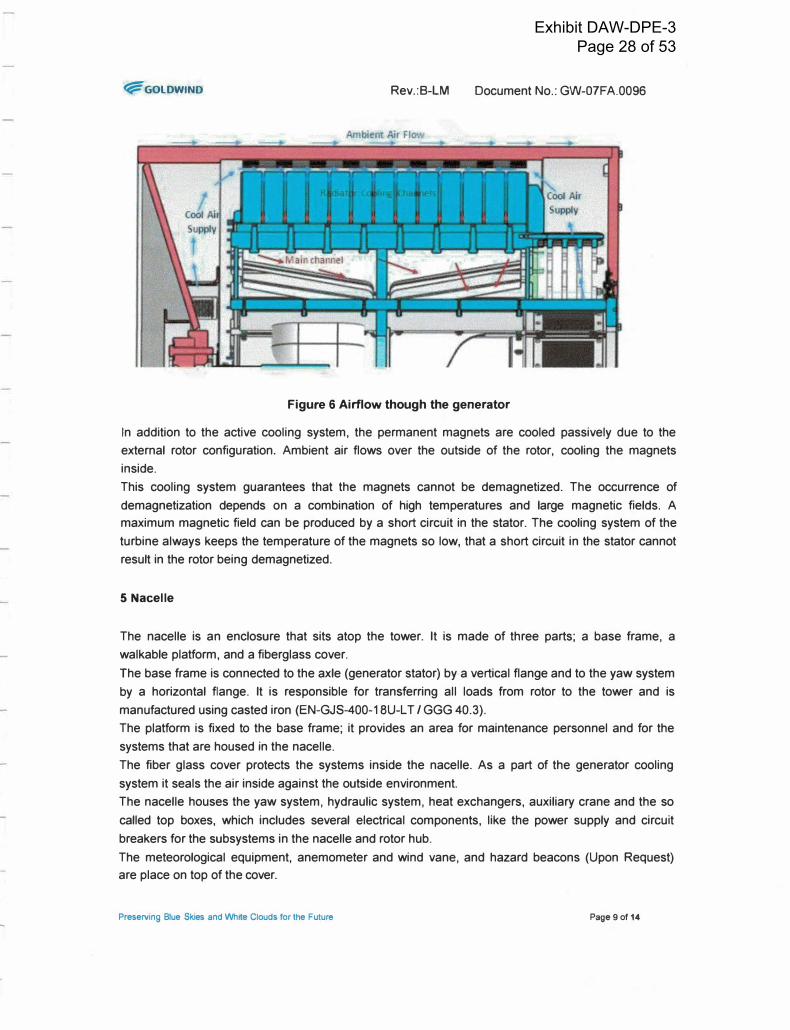
Figure 6 Airflow though the generator
In addition to the active cooling system, the permanent magnets are cooled passively due to the
external rotor configuration. Ambient air flows over the outside of the rotor, cooling the magnets
inside.
This cooling system guarantees that the magnets cannot be demagnetized. The occurrence of
demagnetization depends on a combination of high temperatures and large magnetic fields. A
maximum magnetic field can be produced by a short circuit in the stator. The cooling system of the
turbine always keeps the temperature of the magnets so low, that a short circuit in the stator cannot
result in the rotor being demagnetized.
5 Nacelle
The nacelle is an enclosure that sits atop the tower. It is made of three parts; a base frame, a
walkable platform, and a fiberglass cover.
The base frame is connected to the axle (generator stator) by· a vertical flange and to the yaw system
by a horizontal flange. It is responsible for transferring all loads from rotor to the tower and is
manufactured using casted iron (EN-GJS-400-1 BU-LT I GGG 40.3).
The platform is fixed to the base frame; it provides an area for maintenance personnel and for the
systems that are housed in the nacelle.
The fiber glass cover protects the systems inside the nacelle. As a part of the generator cooling
system it seals the air inside against the outside environment.
The nacelle houses the yaw system, hydraulic system, heat exchangers, auxiliary crane and the so
called top boxes, which includes several electrical components, like the power supply and circuit
breakers for the subsystems in the nacelle and rotor hub.
The meteorological equipment, anemometer and wind vane, and hazard beacons (Upon Request)
are place on top of the cover.
Preserving Blue Skies and WMe Clouds for the Future Page 9 of 14
Exhibit DAW-DPE-3 Page 28 of 53

'1i=GOLDWIND Rev.:B-LM Document No.: GW-O?FA.0096
5.1 Yaw System
The yaw system turns the rotor / turbine head into the wind and adjusts its position as the wind
direction changes. The wind direction is monitored by a wind vane on the nacelle cover, which sends
a signal to the turbine controller to yaw the nacelle as the wind direction changes.
Induction Motor
Base Frame
-- Slew Bearing Outer Ring BrakeDlsk -
Hydraulic Brakes ---1-------
-
----
� Gear Pinion
Tower Top Flange
Figure 7 Yaw System
The system consists of a fixed system and a rotating system (blue). The fixed system includes the
tower top flange (tower), static brake disk, and outer slew bearing ring, which are all bolted to the
tower. The rotating system contains all components bolted to the base frame of the nacelle. This
includes four induction motors, a number of hydraulic brakes, and the inner ring of the slew bearing.
The induction motors are connected to a four stage planetary gear box. The output of the gear box
drives a pinion aligned with the toothed outer ring of the slew bearing. The motors apply the actuation
force to yaw the nacelle as the wind direction changes.
Hydraulically actuated brakes, located to the inside of the base frame and tower, apply pressure to
the brake disk to keep the turbine head from yawing. Additionally, motor brakes at the second end of
the induction motors add brake torque. During yawing, several brakes are released, while others
keep pressure to eliminate backlash between the gears, which could be induced by wind gusts.
After several full rotations, the turbine will return to its original position to untwist the power and data
cables that run from the nacelle to the base of the turbine.
Preserving Blue Skies and White Clouds for the Future Page 10 of 14
Exhibit DAW-DPE-3 Page 29 of 53
�GOLOWINO Rev.:B-LM Document No.: GW-O?FA.0096
6 Tower
The tower is manufactured using high strength steel in three to five sections, depending on the overall
tower height. Each section contains an inner flange on each end for connecting the segments. The
bottom tower section is bolted to the foundation and the subsequent sectionsare bolted on top.
Towers are equipped with a ladder and safety rail. Upon request an assisted climbing system or an
elevator can be included for maintenance access to the nacelle. Emergency lighting and platforms
are installed throughout the tower in regular intervals.
7 Foundation
The foundation is made of reinforced concrete with an embedded "foundation steel section". A flange
on the top of the foundation steel section connects the first tower section to the foundation.
Standard foundations are designed for each rotor diameter, tower height and wind class of the GW
2.2 MW turbine that meet different standards and a variety of environmental conditions. However,
local standards, soil conditions and other environmental conditions vary considerably from place to
place and it is necessary to design a site specific foundation. Goldwind works together with local civil
engineering firms with the specific local knowledge to design these foundations.
8 Electrical Systems
8.1 Converter
The GW 2.2 MW variable speed system is based on the combination of the PMDD synchronous
generator and the full power IGBT (Insulated Gate Bipolar Transistor) frequency converter. It allows
the generator to operate at the optimized rotor speed from cut in to cut out. Variable frequency AC
power from the generator (linear to the generator rotational speed} enters the converter, and is
converted to match the grid frequency, whether it is SOHz or 60Hz. The converter thus decouples the
generator frequency from the grid frequency. The converter system has its own controller unit (CPU),
separate from the turbine controller.
Preserving Blue Skies and White Clouds for the Future Page 11 of 14
Exhibit DAW-DPE-3 Page 30 of 53

�GOLOWIND Rev.:B-LM Document No.: GW-O?FA.0096
GENERATOR SIDE BREAKER
ACTIVE RECTIFIER (IGBT)
GRID SIDE UTILITY BREAKER MEASUREMENT
MAIN I DC LINK
GRID SIDE INVERTER
(IGBT) GRID SIDE FUSES I TRANSFORMER
LC-FILTER
AC�
_�DC DC�
-�AC
J
CHOPPER HIGH VOLTAGE PROTECTION
(LVRT)
POWER SUPPLY SUB SYSTEMS
I
I I LC-FILTER
� I �--------� �--------____, I �
NACELLE I
INSIDE TOWER I
OUTSIDE
TOWER
Figure 8 GW 2.2MW Electrical Diagram
The three phase power output from the generator enters an IGBT active rectifier that converts the AC
generator output to DC. An IGBT inverter then converts the DC back to AC at the required grid
frequency and supplies a sinusoidal current. The microprocessor controlled power electronics (IGBTs)
allow the system to be adapted to various grid requirements by software adjustments.
The DC-Link and capacitor are responsible for maintaining the balance between the generated and
output power. If the grid doesn't take the output of the rectifier (ex. grid fault), there will be a voltage
increase in the DC link. To protect the IGBT modules and to allow the turbine to stay connected to the
grid, for example during a "low voltage ride though" (LVRT), the high voltage protection circuit will limit
the excess voltage by dumping the load through a resistor.
Harmonic filters are located on the generator and the grid side of the converter. They support the
overall power quality of the system and ensure grid standards are met. Fuse boxes and circuit
breakers are able to disconnect the generator and converter from the grid.
To meet any present grid requirement and most future grid requirements the PMDD - full converter
system is a perfect base to be adapted, solely by software modifications.
The converter, located at the base of the tower, is a modular system that can be easily serviced.
The power supply to the subsystems in the turbine is taken directly from the grid. This includes the
power supply for the main controller, which is backed up by an uninterruptable power supply (UPS).
8.2 Main Turbine Transformer
The transformer is located downstream to the converter and transforms the low voltage output of the
turbine to medium voltage level. The standard is to place the transformer outside of the tower;
however, it can be placed inside as well.
Preserving Blue Skies and White Clouds for the Future Page 12 of 14
Exhibit DAW-DPE-3 Page 31 of 53
�GOLDWIND Rev.:B-LM Document No.: GW-O?FA.0096
9 Turbine Controller
The turbine controller manages all functions and sub controllers of the turbine; it optimizes the loads
and energy output, depending on utility and customer demand.
GENERATOR
PITCH 1
PITCH 2
PITCH 3
,. ,.
DC AC
J
L - - .!-_----------,,
HYDRAULIC
SYSTEM
,1
:: ,' ,,
::,,,,,, ,, ,, ,,,,,,,' ,' ,,
CONVERTER CONTROLLER
Power
v ar1d I p1d Speed Temp. Torque Power factor crs STS IV) (A) (rpm) ('C) (Nm) (kW) (d•II tdic••Q Ide I)
L - - - : :_-_-_-::��i{{��-�-�-{._:._:._{:.:.:.L - _ j...... ,,.
&_-__ -- ---- -- --,•,11•,1, ,., ... ,.,
,---...U..-"""""-----�
CTS(dJaiUQ � J, STStdJaiUQ �..J YAW SYSTEM
CTS: Control signal (digital signal). e.g. Reset parameters, open/dose valves, etc. STS: State signal {digital signal). e.g. Motors switched on/off, brokers open/dose, etc.
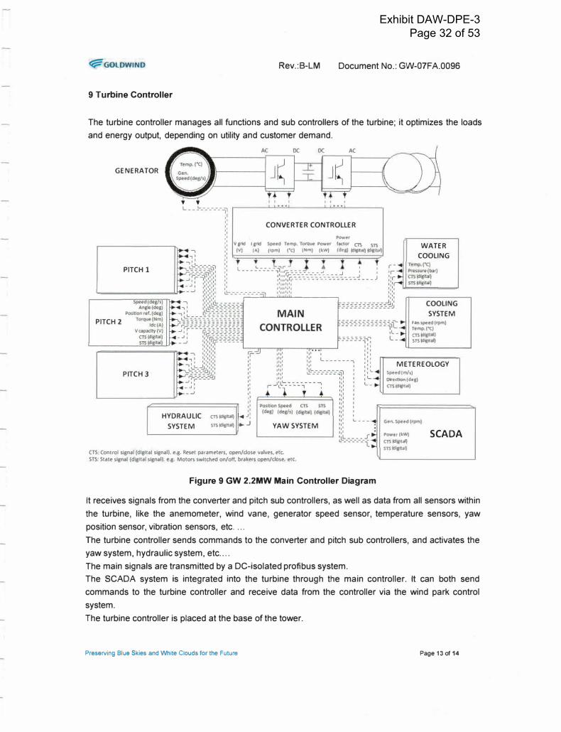
Figure 9 GW 2.2MW Main Controller Diagram
WATER
COOLING
COOLING
SYSTEM
Fan speed (rpm) Temp.("() CTS(d aij STS(d,gltaQ
METEREOLOGY
Spud(m/s}
Dlr•ctfon (d•1) CTS (dfllltaQ
Gen. Speed (rpm)
Powor(kW) CTS (d taQ STStd lll)
SCADA
It receives signals from the converter and pitch sub controllers, as well as data from all sensors within
the turbine, like the anemometer, wind vane, generator speed sensor, temperature sensors, yaw
position sensor, vibration sensors, etc ....
The turbine controller sends commands to the converter and pitch sub controllers, and activates the
yaw system, hydraulic system, etc ....
The main signals are transmitted by a DC-isolated profibus system.
The SCADA system is integrated into the turbine through the main controller. It can both send
commands to the turbine controller and receive data from the controller via the wind park control
system.
The turbine controller is placed at the base of the tower.
Preserving Blue Skies and White Clouds for the Future Page 13 of 14
Exhibit DAW-DPE-3 Page 32 of 53

�GOLDWINO Rev.:B-LM Document No.: GW-O?FA.0096
10 SCADA (Supervisory Control and Data Acquisition)
The turbine can be controlled and monitored externally through the wind farm control system at the
wind farm. The turbine can be monitored by the Goldwind SCADA system via any computer with
internet access.
Both current and historical turbine operating data can be viewed from a SCADA terminal. Various
levels of security exist within the systems, allowing the customer to choose specific access levels.
11 Goldwind121-2.2MW Wind Turbine Technical Data
Table 1 Goldwind121-2.2MW Wind Turbine Technical Data
Technical Data GW121/2200 Power Rated Power 2200 kW
Cut-in Wind Speed 3 m/s
Rated Wind Speed 8.9m/s
(Static)
Cut-out Wind Speed 22 mis (10-minute Average)
Operating Temp.* -30"C to 40"C
Standby Temp.* .4o·c to so·c
Rotor Diameter 121 m
Number of Blades 3
Swept Area 11329 m2
Blade Pitch Control Power Control
Hydraulic Disk Brake for Yaw system
Rotor Lock (for maintenance only)
Safety System Generator Permanent Magnet Direct Drive Synchronous Generator
Rated Voltage 690 V
Yaw System 4 Induction Motors
Tower Tubular Steel Tower
Hub Height 90m
Foundation Anchor Bolts Foundation
Converter Full Scale Converter (IGBT Modules)
Transformer Input Voltage 690V
Output Voltage 33kV (Others Possible)
Control System Microprocessor Controlled, DFO (SCADA)
Design Standard IEC 1118 or below
*According to IEC standard, the Operating Temp. Range is -1o·c to 40"C and Standby Temp. Range is -2o·c to so·c. However,
Goldwind product could extend these ranges larger as shown on the table thanks to good wind turbine performance.
Preserving Blue Skies and White Clouds for the Future Page 14 of 14
Exhibit DAW-DPE-3 Page 33 of 53

APPENDIXD
Circuit Map
17
Exhibit DAW-DPE-3 Page 34 of 53

-.
I
I I
I
I
I I
I
,,_.,., CKT 2 /
WEST &ljARLESTON
SUBSTATION 5.0/7.0 t.4VA 46/12.47KV "l
DAIRY AIR
HOLLAND
2 ACSR
DRAWN: ORC
Vermont Electic Cooperative Johnson, Vermont
DAIRY AIR HOLLAND
Appendix D DWG. No. I
LOCATION: HoHand. �ant
CHECKED: APPROVED:
SCALE: NONe °"TE: B/31/16 SHEET I of 1
Exhibit DAW-DPE-3 Page 35 of 53

APPENDIXE
PSB Rule 5.505
18
Exhibit DAW-DPE-3 Page 36 of 53
Effective: September 10, 2006 Vermont Rule 5.500
Public Service Board Page 6-8 of 21
5.505 Fast Track Screening Process
(A) Within 15 business days after the Interconnecting Utility notifies the Interconnection
Requester it has received a complete Application, the Interconnecting Utility shall
perform a review of the Application under the Fast Track Screening Criteria set forth
below, shall notify the Interconnection Requester of the results, and shall include with the
notification copies of the analysis and data underlying the Interconnecting Utility's
determinations under the Fast Track Screening Criteria.
(B) Fast Track Screening Criteria
(1) The Interconnection Requester's proposed Generation Resource meets the
applicable codes and standards of Section 5.510 or is a certified equipment
package under Section 5.511.
(2) The proposed interconnection point is not at transmission voltage (i.e., not over 23
kV line to line or 13.28 kV line to neutral).
(3) For interconnection to a Radial Feeder, the aggregated generation, including the
proposed Generation Resource, on the circuit will not exceed 15% of the line
section annual peak load as most recently measured at the substation. A line
section is that portion of a distribution system connected to a customer bounded
by Automatic Disconnect Devices or the end of the distribution line.
(4) The aggregated generation, including the proposed Generation Resource, on a
distribution circuit will not contribute more than 10% to the distribution circuit's
maximum fault current at the point on the high voltage (primary) level nearest the
proposed interconnection point.
(5) The aggregated generation, including the proposed Generation Resource, on a
distribution circuit will not cause any distribution protective devices and
equipment (including, but not limited to, substation breakers, fuse cutouts, and
line reclosers), or customer equipment on the system to exceed 85% of the shortcircuit
interrupting capability; nor is the Generation Resource proposed for a
circuit that already exceeds 85% of the short-circuit interrupting capability.
(6) For interconnection of a proposed single-phase or effectively-grounded threephase
Generation Resource where the primary distribution system is three-phase,
four-wire, the Generation Resource will be connected line-to-neutral. For
interconnection of a proposed single-phase or three-phase Generation Resource
where the primary distribution system is three-phase, three-wire, the Generation
Exhibit DAW-DPE-3 Page 37 of 53
Resource will be connected line-to-line.
{7) Voltage drop due to starting the proposed generator is within acceptable limits,
meaning that inrush current, due to starting the proposed Generation Resource up
to once per hour, is not greater than 3% of the available fault current. Voltage
drop due to starting the proposed Generation Resource more than once per hour
meets a tighter inrush-current tolerance, to be determined by the Interconnecting
Utility.
{8) For any single Generation Resource, the available utility short circuit current at
the Point of Interconnection divided by the rated output current of the Genera.tion
Resource is no less than:
{a) 50 for Generation Resources of less than 100 kW;
{b) 40 for Generation Resources from 100 kW to less than 500 kW; and
{c) 20 for Generation Resources equal to or greater than 500 kW.
(9) Aggregate generation, including the Generation Resource, on a circuit will not
exceed 2 MVA in an area where there are known or posted transient stability
limitations to generating units located in the general electrical vicinity {e.g., three
or four busses from the point of interconnection).
{10) No System Upgrades, in excess of limited preparations that do not necessitate a
Facilities Study, are required to facilitate the interconnection of the Generation
Resource.
{11) For interconnection of the proposed Generation Resource to the load side of spot
network protectors, the proposed Generation Resource utilizes inverter-based
equipment and aggregate generation, including proposed Generation Resource,
will not exceed the smaller of 5% of a spot network's maximum load or 50 kW.
Synchronous generators cannot be connected to a secondary network.
{12) If the Generation Resource is to be connected on a shared, single-phase secondary,
aggregate generation capacity on the shared secondary, including the proposed
generation, will not exceed 20 kV A.
{13) If the Generation Resource is single-phase and is to be interconnected on a center
tap neutral of a 240 volt service, its addition will not create an imbalance between
the two sides of the 240 volt service of more than 20% of the service transformer
nameplate.
Exhibit DAW-DPE-3 Page 38 of 53
APPENDIXF
Substation Load Duration Curve
19
Exhibit DAW-DPE-3 Page 39 of 53

MW
0 0 � � N N w .
0 u, 0 u, 0 u, 0
0 0 0 0 0 0 0
0 0 0 0 0 0 0
1
464 V,
927 C
1390 "' r+
1853 QJ
2316 r+ -·
2779 0 ::,
3242
3705 0
4168 QJ
4631 C.
5094 C
5557 C -,
6020 QJ r+
6483 -·
0 6946 ::,
7409 n 7872 C
8335
Exhibit DAW-DPE-3 Page 40 of 53

APPENDIXG
IEEE 154 7 2014 Amendment
20
Exhibit DAW-DPE-3 Page 41 of 53

IEEE Standard for Interconnecting Distributed Resources with Electric Power Systems
Amendment 1
IMPORTANT NOTICE: IEEE Standards documents are not intended to ensure safety, security, health, or environmental protection, or ensure against interference with or from other devices or networks. , Implementers of IEEE Standards documents are responsible for determining and complying with all appropriate safety, security, environmental, health, and interference protection practices and all applicable laws and regulations.
This IEEE document is made available for use subject to important notices and legal disclaimers. These notices and disclaimers appear in all publications containing this document and may be found under the heading "Important Notice" or "Important Notices and Disclaimers Concerning IEEE Documents." They can also be obtained on request from IEEE or viewed at http://standards.ieee.orgRPRldisclaimers.html.
NOTE-The editing instructions contained in th.is <amendment/corrigendum> define how to merge the material contained therein into the existing base standard and its amendments to form the comprehensive standard.
The editing instructions are shown in bold italic. Four editing instructions are used: change, delete, insert, and replace. Change is used to make corrections in existing text or tables. The editing instruction specifies the location of the change and describes what is being changed by using strilEelbe1:1gh (to remove old material) and underscore (to add new material). Delete removes existing material. Insert adds new material without disturbing the existing material. lnsertions may require renumbering. If so, renumbering instructions are given in the editing instruction. Replace is used to make changes in figures or equations by removing the existing fib'llre or equation and replacing it with a new one. Editing instructions, change markings, and this NOTE will not be carried over into future editions because the changes will be incorporated into the base standard.
Copyright© 2014 IEEE. All rights reserved.
! (1) -, .... Q) ..... ..... .... n en :, (/) (1) 0..
,+ 0
0 Q) :, .... ro ..... n -, g """(1) .+
..... .... n (1) :, (/) (1) (1)
C: (/) en
g .....
IC
n 0 "O IC -, .... "" :r ,+ (1) 0..
Q) :, C.
:i,
� :r 0 -, .... N (1) C.
C" IC
"!:? (/) ,+ -, .... n .+ .... 0
i;l :i, "O "O
:E
Exhibit DAW-DPE-3 Page 42 of 53

Change Clause 2 as follows:
2. Normative references
ANSI C84.l-2011+9%, Electric Power Systems and Equipment-Voltage Ratings (60 Hz).
4. Interconnection technical specifications and requirements
4.1 General requirements
4.1.1 Voltage regulation
Change 4.1.1 as follows:
The DR shall eat aetiYely Feg11late the Yelt&ge et the PCC. Coordination with and approval of. the area EPS and DR operators, shall be required for the DR to actively participate to regulate the voltage by changes of real and reactive power. The DR shall not cause the Area EPS service voltage at other Local EPSs to go outside the requirements of ANSI C84.l-20J l .J.-9%, Range A.
4.2 Response to Area EPS abnormal conditions
4.2.3 Voltage
Change 4.2.3 as follows:
The protection functions of the interconnection system shall detect the effective (rms) or fundamental frequency value of each phase-to-phase voltage, except where the transformer connecting the Local EPS to the Area EPS is a grounded wye-wye configuration, or single-phase installation, the phase-to-neutral voltage shall be detected.
When any voltage is in a range given in Table I, the DR shall cease to energize the Area EPS within the clearing time as indicated. Under mutual agreement between the EPS and DR operators. other static or dynamic voltage and clearing time trip settings shall be permitted. Clearing time is the time between the start of the abnormal condition and the DR ceasing to energize the Area EPS. For DR less than or equal to � 300 W in peak capacity, the voltage set points and clearing times shall be either fixed or fieldadjustable. For DR greater than � 300 W, the voltage set points and clearing times shall be fieldadjustable.
The voltages shall be detected at either the PCC or the point of DR connection when any of the following conditions exist:
a) The aggregate capacity of DR systems connected to a single PCC is less than or equal to 30 kW,
b) The interconnection equipment is certified to pass a non-islanding test for the system to which it isto be connected,
2
Copyright© 2014 IEEE. All rights reserved.
n 0 'C "' -, .... "" ::r ,+
� al � .... Ol ....
.... .... n
(/) ro a.
,+ 0
0 a, :, .... ro ....
n
g 1<'
�
g N 0 ...
"'
0 � �
.... .... n ro :, (/) ro ro
C: (/) ro
g ...."'
n 0 'C "' -, .... "" ::r ,+
ro a.
a, :, a.
:J> C: ,+
::r
Sl .... N ro a.
er "' H ,..,,..,,..,
ii? (/) ,+
-, .... n ,+
.... 0 :, (/)
:J> 'C 'C ...."'
Exhibit DAW-DPE-3 Page 43 of 53

c) The aggregate DR capacity is less than 50% of the total Local EPS minimum annual integrated
electrical demand for a 15 minute time period, and export of real or reactive power by the DR to
the Area EPS is not permitted.
Delete the current Table 1 as follows:
Table 1 IRtersoRRestioR system respoRse to abRormal voltages
Veltsge Nnge Cleent1g time(s)"
(% eJ hese .,.eltsge1
� �
S9 � ¥..::. 88 �
irnc:.¥..::.rw 4-,00
¥ � 1;!9 �
-Be:se veUages !l:fe the Aemiea! systeffl 1,·eltages states ifl ,"L"1SI C84. I 1995, Table l.
·�. 3Q lcW, m�ciRUIR� ele&riRg times; DR> 391cV,', Elefmilt ele&riRg times.
Insert a new Table 1 as follows:
Table 1-lnterconnection svstem default response to abnormal voltages
Default settings•
Voltage range(% of Clearing time Clearing time: adjustable up to and
base voltagei (s) including (s)
V<45 0.16 0.16
45<V <60 l 11
60<V <88 2 21
110 <V < 120 I 13
V> 120 0.16 0.16 8 Under mutual agreement between the EPS and DR operators, other static or dynamic voltage and clearing time trip settings shall be permitted b Base voltages are the nominal system voltages stated in ANSI C84.1-2011, Table I.
3
Copyright© 2014 IEEE. All rights reserved.
(") 0 "C IC -, .... OQ
;! �
ffl .+
� .... Q) ,-
,..... n (1) :, "' (1) Cl.
,+ 0
ai' :, .... (1) ,-
n -, g ><" (1) ,+
0 :,
N 0 ...."'' 0
� 0 a,
,.... n
� "' n, (1)
C: V) (1)
g,IC
n 0
;g -, ..... 0Q. :,,+ (1) Cl.
Q) :, C.
;p C: ,+
5 -, ..... N (1) C.
CIC
H rr, rr, rr,
"' (1)
-, .... n ,+ .... 0
iii ;p
"C "C ,IC
Exhibit DAW-DPE-3 Page 44 of 53

4.2.4 Frequency
Change 4.2.4 as follows:
When the system frequency is in a range given in Table 2, the DR shall cease to energize the Area EPS within #te a pre-set clearing time as indicated. Under mutual agreement between the EPS and DR operators. other static or dynamic frequency and clearing time trip settings shall be permitted. Clearing time is the time between the start of the abnormal condition and the DR ceasing to energize the Area EPS. FeF DR less thaA er l!EjUal te 30 kW ifl 13eak ea13aeit:y, the frequeAey set 13eiHts aHd elearieg times shall be either fi>Eed er field adjustable. Fer DR greater thae 30 kW, the frequeAey set 13eiAt:s shall be field adjustable.
The frequency and time set points in Table 2 shall be field adjustable. Adjustable under-frequency (UF) and over-frequency (OF) trip settings shall be coordinated with the Area EPS operatortieas. DR settings for frequency response shall be coordinated with load shedding schemes of the Area EPS.
As mutually agreed upon by the Area EPS and DR operators, DR shall be permitted to provide modulated power output as a function of frequency in coordination with functions UFL UF2. OF L and OF2. Operating parameters shall be specified when this function is provided.
Delete the current Table 2 as follows:
Table 2 IRteF68RR8Gti8R &y&teFR re&p8R68 te abR8FFRal frequeRGie&
D.R-5ii!e li'.Feq11et1�' Feege (Iii!) Gle11Fi:Rg time(st
� :53g lcW
� �
� �
> 3Q lc1,ll .:; (S9.8 S+.QJ Aeljustaele Q. le te 300
�11Elj11s1:eele set f!eifll)
� �
DR< 3Q kW, !llll!Hfllliffl el@BRRg linies; DR> 3Q kW, Eiefa11lt elear.ng limes.
Insert a new Table 2 as follows:
Table 2--lnterconnection system default response to abnormal frequencies
Default settings Ranges of adjustability
Function Frequency Clearing Frequency Clearing time (s) (Hz) time (Hz) adjustable up to and
(s) includine: UFI < 57 0.16 56-60 10
UF2 <59.5 2 56-60 300
OF1 > 60.5 2 60-64 300
OF2 > 62 0.16 60-64 10
4
Copyright© 2014 IEEE. All rights reserved.
n 0
"C
� .... "" ::T r+ (1) Cl.
� r+
!ll .... Ql .... ........ n (1) :, (I) (1) Cl.
r+ 0
0 Ql :, .... (1) .... n
g .,,.. ro r+
g "' 0 ...
"'' 0 "' '
0 CD
.... � ........ n (1) :, (I) (1) (1)
C: (I) ro
0 :, ....
IC
n 0 "C IC , ..... "" ::T r+ ro Cl.
Ql
5. :I> C: r+
� .... N (1) Cl.
CT IC
,., ro
!:i , ....n r+ .... 0 :, (I)
:I> "C "C .... IC
Exhibit DAW-DPE-3 Page 45 of 53

APPENDIXH
Fast Track Screening
21
Exhibit DAW-DPE-3 Page 46 of 53
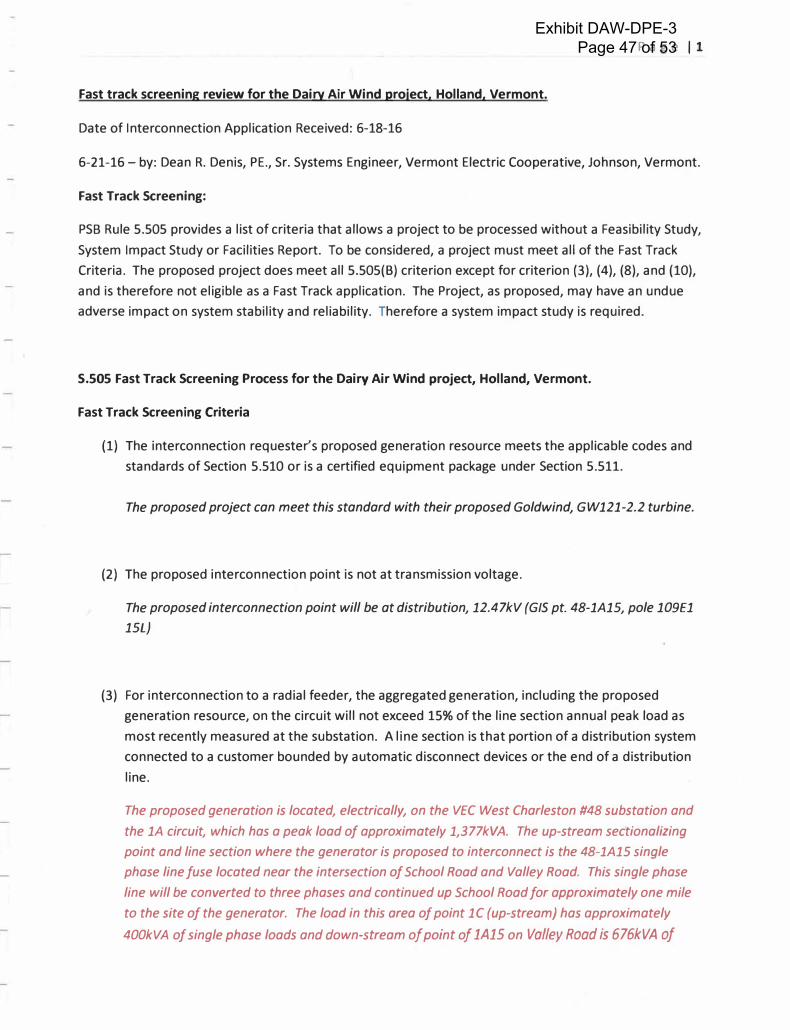
Fast track screening review for the Dairy Air Wind project, Holland, Vermont.
Date of Interconnection Application Received: 6-18-16
P a g e 11
6-21-16 - by: Dean R. Denis, PE., Sr. Systems Engineer, Vermont Electric Cooperative, Johnson, Vermont.
Fast Track Screening:
PSB Rule 5.505 provides a list of criteria that allows a project to be processed without a Feasibility Study,
System Impact Study or Facilities Report. To be considered, a project must meet all of the Fast Track
Criteria. The proposed project does meet all 5.505(8) criterion except for criterion (3), (4), (8), and (10),
and is therefore not eligible as a Fast Track application. The Project, as proposed, may have an undue
adverse impact on system stability and reliability. Therefore a system impact study is required.
S.505 Fast Track Screening Process for the Dairy Air Wind project, Holland, Vermont.
Fast Track Screening Criteria
(1) The interconnection requester's proposed generation resource meets the applicable codes and
standards of Section 5.510 or is a certified equipment package under Section 5.511.
The proposed project can meet this standard with their proposed Goldwind, GW121-2.2 turbine.
(2) The proposed interconnection point is not at transmission voltage.
The proposed interconnection point will be at distribution, 12.47kV {GIS pt. 48-1A15, pole 109£1
15L}
(3) For interconnection to a radial feeder, the aggregated generation, including the proposed
generation resource, on the circuit will not exceed 15% of the line section annual peak load as
most recently measured at the substation. A line section is that portion of a distribution system
connected to a customer bounded by automatic disconnect devices or the end of a distribution
line.
The proposed generation is located, electrically, on the VEC West Charleston #48 substation and
the 1A circuit, which has a peak load of approximately 1,377kVA. The up-stream sectionalizing
point and line section where the generator is proposed to interconnect is the 48-1A15 single
phase line fuse located near the intersection of School Road and Valley Road. This single phase
line will be converted to three phases and continued up School Road for approximately one mile
to the site of the generator. The load in this area of point 1C (up-stream) has approximately
400kVA of single phase loads and down-stream of point of 1A15 on Valley Road is 676kVA of
Exhibit DAW-DPE-3 Page 47 of 53

Pa g e 12
three phase loads. Therefore, the 2,200kW generator exceeds 100% of the line section's annual
peak load and fails this criterion. Being located approximately 8. 7 miles from the West
Charleston Substation creates concerns of possible voltage rise at peak generation output and
low loading times. This will need to be analyzed further in a full system impact study.
(4) The aggregated generation, including the proposed generation, on a distribution circuit will not
contribute more than 10% to the distribution circuit's maximum fault current at the point on the
high voltage (primary) level nearest the proposed interconnection point.
The fault current near the point of interconnection on Valley Road is approximately 494 Amps.
Fault current tests per UL 1741 certification indicate that the fault tests to ground, output
current was measured to be 1.1 p.u. (peak) worst case except for a very short duration transient
current spike of 2.7 p.u. (peak) at the moment the fault was initiated during the all three phase
to ground test. During the phase to phase tests, output current measured to be 1.2 p.u. (peak)
worst case except for some very short duration transient current spikes with a maximum of 2.5
p.u (peak). Worst case output current during fault conditions was 1.2 p.u (rms). The very short
duration current spikes observed in both the phase to ground and phase to phase tests were all
less than 0.20 ms. These spikes resulted from discharge of filter capacitors in the phase to phase
AC output filter inside the inverter.1 10% of 494 is 49 Amps; Full load output of 2,200kW
inverters is 102 Amps; 1.2pu of 102 Amps is 122 Amps and represents 122/494 = 25% of the VEC
fault current near the point of interconnection. The proposed inverter based wind projects fail
this criterion.
(5) The aggregated generation, including the proposed generation, on a distribution circuit will not
cause any distribution protective devices and equipment (including, but not limited to,
substation breakers, fuse cut-outs, and line reclosers), or customer equipment on the system to
exceed 85% of the short circuit interrupting capability; nor is the generation proposed for a
circuit that already exceeds 85% of the short circuit interrupting capability.
Please refer to Answer (4) above for explanation of the limited fault current contributions from
inverter based generation. The project meets this criterion.
(6) For interconnection of a proposed single-phase or effectively grounded three phase generator
where the primary distribution system is three phase, four wire, the generator will be connected
line to neutral.
The generator will be connected to a grounded wye 12.47/7.2kV distribution system at three
phase secondary voltages.
1 Advanced Energy, April 23, 2014, implementation of protection to mitigate faults due
to phase faults for 1 OOONX Inverters.
Exhibit DAW-DPE-3 Page 48 of 53

Pa g e 13
(7) Voltage drop due to starting the proposed generator is within acceptable limits, meaning that
inrush current, due to starting the generation up to once per hour, is not greater than 3% of the
available fault current. Voltage drop due to starting the proposed generator more than once
per hour meets a tighter inrush-current tolerance, to be determined by the interconnecting
utility.
The inverters do not require nor produce inrush currents to start. The project meets this
criterion.
(8) For any single generation resource, the available utility short circuit current at the point of
interconnection divided by the rated output current of the generation resource is no less than:
SO for generators of less than lOOkW;
40 for generators from lOOkW to less than SOOkW; and
20 for generators equal to or greater than SOOkW.
The three phase fault current at the point of interconnection is approximately 494 Amps. The
rated output current of a 2,200kW generator is 102 Amps. 494 /102 = 4.8, which is less than the
minimum of 20. The project fails this criterion.
(9) Aggregate generation, including the proposed generator(s), on a circuit will not exceed 2MVA in
an area where there are known or posted transient stability limitations to generating units
located in the general electrical vicinity (e.g., three or four busses from the point of
interconnection).
There are no known transient stability limitations, however the generation resource does exceed
the 2MVA threshold and will be further analyzed in a system impact study.
(10) No system upgrades, in excess of limited preparations that do not necessitate a Facilities Study,
are required to facilitate the interconnection of the generator.
There is not existing three phase distribution conductor to the project location on School Road.
An approximately 1 mile long line extension will need to be built in order to interconnect the
project to the VEC system.
Exhibit DAW-DPE-3 Page 49 of 53

Pa g e 14
(11) For interconnection of the proposed generator to the load side of spot network protectors, the
proposed generator utilizes inverter-based equipment and aggregate generation, including
proposed generation, will not exceed the smaller of 5% of a spot network's maximum load or
SOkW. Synchronous generators cannot be connected to a secondary network.
The generation resource will not be connected to a spot network.
(12) If the generator is to be connected on a shared, single phase secondary, aggregate generation
capacity on the shared secondary, including the proposed generator, will not exceed 20kVA.
The generation resource will not be connected to a shared, single phase secondary.
(13) If the generator is single phase and is to be interconnected on a center tap neutral of a 240 Volt
service, its addition will not create an imbalance between the two sides of the 240 Volt service
of more than 20% of the service transformer nameplate (capacity).
The generation resource will not be single phase or connected on a center tap neutral of a 240V
service.
Exhibit DAW-DPE-3 Page 50 of 53
APPENDIX I
Cost Estimate
22
Exhibit DAW-DPE-3 Page 51 of 53

VERMONT ELECTRIC
Construction Worksheet -2016 C
Member: All 1:arth Kenewables
Project Manager / Engineer: Dean Denis
Below is the estimate for the following project: Morgan Solar - Valley Road
Project Description: Morgan Sdar generator, lhree phase interconnection facilitles, Valley Road, MOl'gan, vr. This cost estimate 11 non-binding. Project will incur adual VEC costs for materials and labor, including overheads. Prepayments req..iired, true up at comP,etion.
Total Labor Hours 776.00 Total Labor $ 79,090.10 Total Transportation Hours 373.00 Total Transportation $ 27,162.99
Material List: 167kVA overhead service transformer SCADA communication path (radio from substation to site
Aluma-Form large transformer duster mount Voltage Regulators - 114.3 kVA 7,620V, 150 A
Direct Charges Three phase load break switch with motor operator Regulator Bv Pass - 15 kV L.i'le meterials - 110 AAAC, misc - m, LAs, brackets, wd, terms, etc (See Materials
SCADA at site Sheet) Secondary CT metering
Station service
Total Materials $ 127,959.50
Total Estimate $ 234,212.59
This is just an ESTIMATE and will reQuire a True-up at time of completion.
SIGNATURES/AUTHORIZATIONS:
Worksheet Submitted By: Date: . .
-- -�-
Project Manager/Engineer : Dean Denis
Member Approved By: Date: ---- �
Member : All Earth Renewables
Work Order#: 0
Member Copy
Exhibit DAW-DPE-3 Page 52 of 53

Dairy Air Wind, LLC
94 Harvest Lane
Williston, VT 05495
Re: Addendum to the Dairy Air Wind Generation Project System Impact Study dated August, 2016
This addendum serves to clarify the details and ensure agreement between the "System Description" in
Section 2 and the "System One-Line Drawing" included as Appendix A of the Dairy Air Wind ("DAW")
System Impact Study ("SIS"). The SIS was prepared by Crocket Engineering on behalf of the Vermont
Electric Cooperative ("VEC"), for the proposed DAW project. The SIS contains discrepancies between the
System Description and the System One-Line Drawing.
The SIS currently includes the following description of the new generation step-up transformer:
"The new generation step-up transformer has been specified with a nameplate rating of 2750 kVA,
12.5GrdY /7 .2 volt wye -690 Delta- 398 grounded wye configuration, and 7% impedance."
In order for the new generation step-up transformer description within the System Description to match
the agreed upon System One-Line Drawing, the description of the new generation step-transformer
should be revised as:
"The new generation step-up transformer has been specified with a nameplate rating of 2750 kVA,
12.5kV Delta - 690/398 V Grounded Wye configuration, and 7% impedance."
This Addendum to the SIS will serve as a revision of the System Description which has been mutually
agreed upon by the DAW project and VEC.
Exhibit DAW-DPE-3 Page 53 of 53


![Evaluation of Requirements for Volt/Var Control and ... · utilities follow the ANSI American National Standards Institute voltage standards (ANSI C84.1-1995) [7]-[9]. The acceptable](https://img.pdfslide.us/doc/110x75/5e7411d0add64c47ed0b5312/evaluation-of-requirements-for-voltvar-control-and-utilities-follow-the-ansi.jpg)


![[ANSI C84.1-2006] Electric Power Systems and Equipment - Voltage Ratings (60 Hertz)](https://img.pdfslide.us/doc/110x75/544b683eaf7959ac438b5204/ansi-c841-2006-electric-power-systems-and-equipment-voltage-ratings-60-hertz.jpg)