Embed Size (px)
Citation preview
Supplement to
Specifications for Electrical InstallationsGeneral Requirements Above 600-Volt ServiceElectric System Bulletin No. 7511
June, 2014(Supersedes all previous versions of ESB 751)

National Grid / Supplement to Specifications for Electrical Installations / ESB 751 June 2014
2 For the latest authorized version please refer to the Company’s website at http://www.nationalgridus.com/electricalspecifications
PREFACE This supplement of the Specifications for Electrical Installations (ESB 750) supersedes previous ESB 751 documents from the Niagara Mohawk Power Corporation legacy company of National Grid.
This supplement covers additional specifications for performance requirements of Company provisions and customer responsibilities where service delivery is greater than 600 Volts and is applicable for the following National Grid companies:
Massachusetts Electric Company
Nantucket Electric Company
The Narragansett Electric Company
Niagara Mohawk Power Corporation
This supplement is available from the Company’s web site and may be obtained:
• From the Internet at http://www.nationalgridus.com/electricalspecifications,
• Or in printed form by contacting either of the Call Centers in Massachusetts or New York (see inside cover of ESB 750). However, printed copies are not document controlled, so for the latest authorized version please refer to the Company’s website.
National Grid / Supplement to Specifications for Electrical Installations / ESB 751 June 2014
For the latest authorized version please refer to the Company’s website at http://www.nationalgridus.com/electricalspecifications. 1
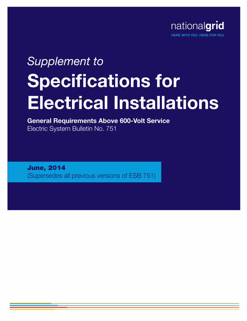
TABLE OF CONTENTS
1.0 INTRODUCTION....................................................................................................... 1 1.1 PURPOSE ..........................................................................................................................1 1.2 SCOPE ...............................................................................................................................1
2.0 CUSTOMER’S RESPONSIBILITIES FOR TAKING SERVICE ABOVE 600 VOLTS........................................................................................................................................ 1
2.1 SERVICE PLAN ..................................................................................................................2 2.2 COMPANY ELECTRIC POWER SYSTEM MODIFICATIONS............................................2 2.4 CODES, STANDARDS, AND REFERENCES.....................................................................2
3.0 DEFINITIONS............................................................................................................ 2 ACRONYMS/SYNONYMS ........................................................................................................3
4.0 GENERAL SERVICE CONNECTION REQUIREMENTS ABOVE 600 VOLTS....... 3 4.1 VOLTAGES AVAILABLE ABOVE 600 VOLTS.....................................................................3
Table 4.1-1 Available Services above 600 Volts (Upstate NY)..............................................3 Table 4.1-2 Available Services above 600 Volts (MA, NH, and RI) .......................................4
4.2 APPLYING FOR SERVICE GREATER THAN 600 VOLTS..................................................4 4.3 DESIGN ACCEPTANCE REVIEW.......................................................................................4 4.4 DESIGN ACCEPTANCE REVIEW PROCESS ....................................................................4
4.4.1 Design Review Summary ............................................................................................5 4.4.2 Submittal of Design Materials to the Company............................................................5 4.4.3 Schedule......................................................................................................................6
5.0 DETAIL DESIGN SUBMITTAL PROCESS ............................................................. 7 STAGE A: PRELIMINARY DESIGN SUBMITTAL PHASE.....................................................................7 STAGE B: DESIGN AND PROCUREMENT PHASE .............................................................................8 STAGE C: CONSTRUCTION AND INSTALLATION PHASE.................................................................11
6.0 COMPLIANCE AND VERIFICATION .................................................................... 11 STAGE D: COMPLIANCE AND VERIFICATION TESTING PHASE .......................................................11 6.1 CUSTOMER NOTIFICATION OF SATISFACTORY COMPLETION OF CONSTRUCTION.................................................................................................................................................11
6.1.1 Required Testing Documentation ...............................................................................11 6.1.2 Customer’s Testing and Commissioning Plan Requirements.....................................12 6.1.3 Relay Witness Testing ................................................................................................12 6.1.4 Company’s Field Audit................................................................................................12 6.1.5 Electrical Inspection by Code Enforcement Authority.................................................12 6.1.6 Customer Operating Agreement and Company Operating Diagram ..........................13 6.1.7 Company’s Right to Operate ......................................................................................13
7.0 ENERGIZATION AND/OR SYNCHRONIZATION ................................................. 13 STAGE E: ENERGIZATION AND SYNCHRONIZATION PHASE...........................................................13 7.1 PREREQUISITES.............................................................................................................13 7.2 AUTHORIZATIONS ..........................................................................................................14 7.3 ENERGIZATION PLAN.....................................................................................................14
7.3.1 Energization Coordinator ...........................................................................................14 7.3.2 Energization Plan Development and Execution.........................................................14 7.3.3 Synchronization .........................................................................................................14
8.0 PROJECT CLOSE OUT ........................................................................................ 15 STAGE F: PROJECT CLOSEOUT PHASE.......................................................................................15
9.0 PERIODIC VERIFICATION.................................................................................... 15 10.0 REVISION HISTORY ........................................................................................... 16 APPENDIX A ................................................................................................................ 17

National Grid / Supplement to Specifications for Electrical Installations / ESB 751 June 2014
For the latest authorized version please refer to the Company’s website at http://www.nationalgridus.com/electricalspecifications. 1
1.0 INTRODUCTION
1.1 PURPOSE This Supplement to Electrical System Bulletin (ESB) 750 provides the Company’s and Customer’s performance requirements for service interconnections greater than 600 Volts. It also provides general design and compliance verification review process requirements for a Customer or Generator-owner who is, or will be supplied by a National Grid (Company) designated voltage in excess of 600 Volts.
It is important that the Customer or Generator-owner and their engineer or contractor obtain and refer to the Specifications for Electrical Installations booklet (ESB 750, latest version) and other applicable ESB 750 series supplements in conjunction with these requirements.
1.2 SCOPE Performance requirements for services above 600 Volts contained herein cover communications with the Company, planning and approval processes, required technical submittals and compliance verification for medium and high voltage customer installations.
Prescriptive requirements for the Customer or Generator-owner shall comply with the appropriate Company Electric System Bulletin (ESB) which covers details for their service installation. These Bulletins include:
ESB 750 - Specifications for Electrical Installations
ESB 752 - Services Above 15,000 Volts
ESB 753 - Primary Meter Pole
ESB 755 - Operation & Maintenance Requirements for Services Above 600 Volts
ESB 756 - Requirements for Parallel Generation Connected to a National Grid Owned EPS
ESB 758 - Primary Service to Metal Enclosed Gear
ESB 759B - Underground Commercial Distribution (UCD) Installation & Responsibility Guide
2.0 CUSTOMER’S RESPONSIBILITIES FOR TAKING SERVICE ABOVE 600 VOLTS
1. The Customer shall consult the Company in every case where the service voltage may exceed 600 Volts. The Company will designate the type of service based on the location, size and nature of the proposed load and its relation to the Company's facilities.
2. Refer to Sections 1.7.2 and 2.0 in ESB 750 for requirement of a Design Professional related to the design of the Customer’s service connection above 600 Volts. In addition, only qualified persons are permitted to install, operate, maintain and/or work on these facilities. Prior to ordering equipment for new or changed services, the Customer must obtain acceptance of their design proposal from the Company. Refer to Section 4.2 in ESB 755.
National Grid / Supplement to Specifications for Electrical Installations / ESB 751 June 2014
2 For the latest authorized version please refer to the Company’s website at http://www.nationalgridus.com/electricalspecifications
2.1 SERVICE PLAN The Company will develop a written Service Plan documenting the method for serving a specific Customer. The Service Plan documents the Company’s method for serving a specific Customer. Electrical studies to support the Service Plan development may require Customer contributions based upon service complexity. Service Plans are generally developed for Customers interconnecting to the Company’s Electric Power System (EPS) at voltages exceeding 15kV. The Service Plan includes, but is not limited to, the specified delivery voltage, required technical submittals for Company review, and verification requirements.
2.2 COMPANY ELECTRIC POWER SYSTEM MODIFICATIONS Company modifications, other than the line extension and service lateral, may be required. These modifications may require funding from the Customer. It is the Customer’s responsibility to obtain for the Company, and/or pay for such environmental and highway permits, rights-of-way and easements from other parties secured by the Company on behalf of the Customer’s project. All cost estimates are required to be paid in full, by the Customer, prior to the commencement of construction activities by the Company, and prior to the interconnection of the Customer’s facility.
2.3 TELECOMMUNICATION SERVICE Depending on the installation, the type and configuration of the service, and at the discretion of the Company, the Customer may need to provide telecommunications circuits and related equipment to ensure coordination with the Company’s electric power system. The cost and coordination of such installations is the responsibility of the Customer. Maintenance of the telecommunications service lines is the responsibility of the telecommunications provider. The Company will specify the required types of telecommunications systems required for coordination with the Company’s Electric Power System (EPS).
2.4 CODES, STANDARDS, AND REFERENCES See Section 1.0 of the Company’s ESB 750 and the other prescriptive ESB 750 Series listed in Section 1.2 above for all applicable codes and standards that the Customer’s installation shall adhere to.
3.0 DEFINITIONS Note: The following are terms defined as used in this publication.
Refer to ESB 750 Section 2.0 and the other prescriptive ESB 750 Series for definitions.
Customer – A “Customer” will be synonymous with a “Generator Owner” for the purpose of this Supplement
Design Professional – A Professional Engineer, authorized and licensed to practice in the respective state or jurisdiction in which the project will be installed and operated
Qualified Person – As defined by the National Electrical Code, is “one who has skills and knowledge related to the construction and operation of the electrical equipment and installations and has received safety training to recognize and avoid the hazards involved”
National Grid / Supplement to Specifications for Electrical Installations / ESB 751 June 2014
For the latest authorized version please refer to the Company’s website at http://www.nationalgridus.com/electricalspecifications. 3
ACRONYMS/SYNONYMS ANSI – American National Standards Institute
Energization - “In Service”
EPS - “Electric Power System”
ESB - “Electric System Bulletin”
IEEE – Institute for Electrical and Electronic Engineering
TOA – “Transmission Outage Authorization”
4.0 GENERAL SERVICE CONNECTION REQUIREMENTS ABOVE 600 VOLTS
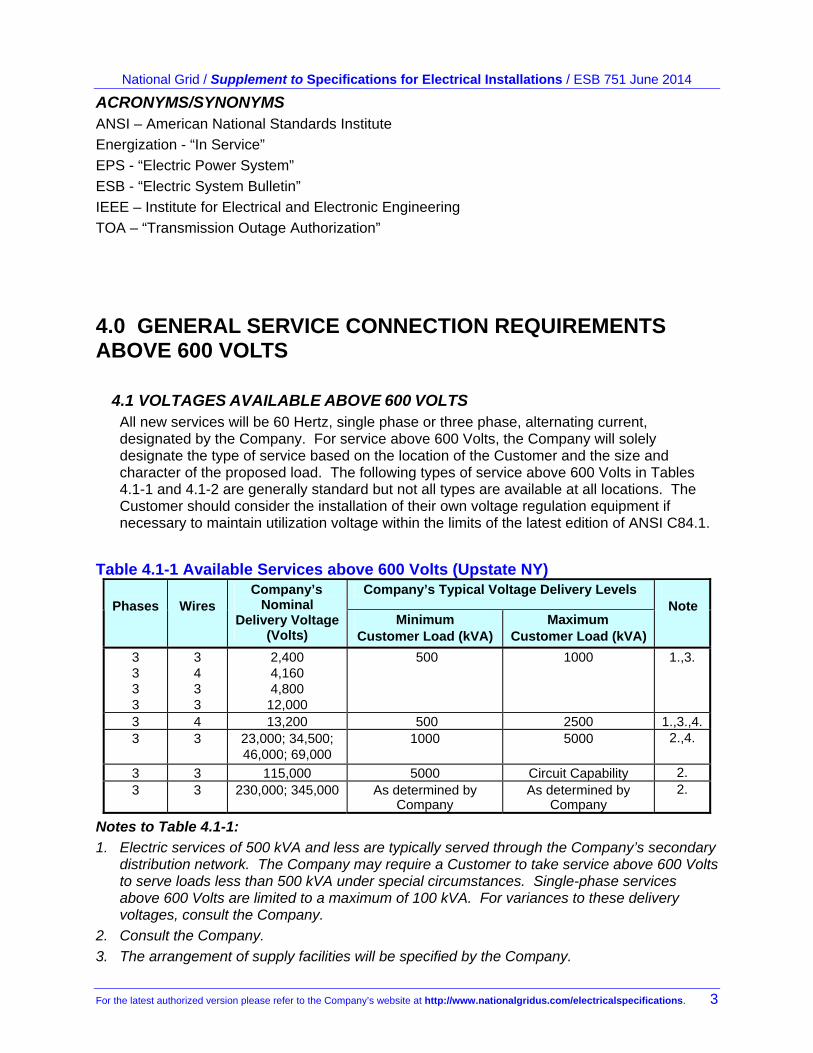
4.1 VOLTAGES AVAILABLE ABOVE 600 VOLTS All new services will be 60 Hertz, single phase or three phase, alternating current, designated by the Company. For service above 600 Volts, the Company will solely designate the type of service based on the location of the Customer and the size and character of the proposed load. The following types of service above 600 Volts in Tables 4.1-1 and 4.1-2 are generally standard but not all types are available at all locations. The Customer should consider the installation of their own voltage regulation equipment if necessary to maintain utilization voltage within the limits of the latest edition of ANSI C84.1.
Table 4.1-1 Available Services above 600 Volts (Upstate NY) Company’s Typical Voltage Delivery Levels
Phases
Wires Company’s
Nominal Delivery Voltage
(Volts) Minimum
Customer Load (kVA) Maximum
Customer Load (kVA)
Note
3 3 3 3
3 4 3 3
2,400 4,160 4,800
12,000
500 1000 1.,3.
3 4 13,200 500 2500 1.,3.,4.3 3 23,000; 34,500;
46,000; 69,000 1000 5000 2.,4.
3 3 115,000 5000 Circuit Capability 2. 3 3 230,000; 345,000 As determined by
Company As determined by
Company 2.
Notes to Table 4.1-1:
1. Electric services of 500 kVA and less are typically served through the Company’s secondary distribution network. The Company may require a Customer to take service above 600 Volts to serve loads less than 500 kVA under special circumstances. Single-phase services above 600 Volts are limited to a maximum of 100 kVA. For variances to these delivery voltages, consult the Company.
2. Consult the Company.
3. The arrangement of supply facilities will be specified by the Company.
National Grid / Supplement to Specifications for Electrical Installations / ESB 751 June 2014
4 For the latest authorized version please refer to the Company’s website at http://www.nationalgridus.com/electricalspecifications
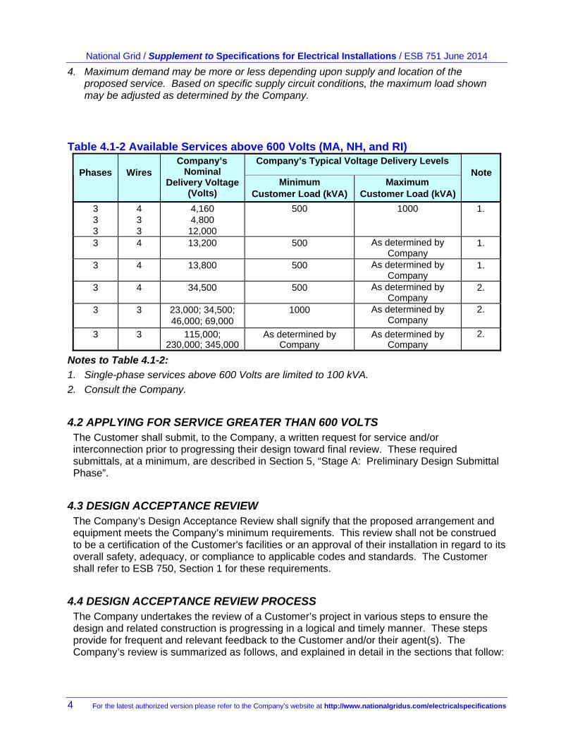
4. Maximum demand may be more or less depending upon supply and location of the proposed service. Based on specific supply circuit conditions, the maximum load shown may be adjusted as determined by the Company.
Table 4.1-2 Available Services above 600 Volts (MA, NH, and RI) Company’s Typical Voltage Delivery Levels
Phases
Wires Company’s
Nominal Delivery Voltage
(Volts) Minimum
Customer Load (kVA) Maximum
Customer Load (kVA)
Note
3 3 3
4 3 3
4,160 4,800
12,000
500 1000 1.
3 4 13,200 500 As determined by Company
1.
3 4 13,800 500 As determined by Company
1.
3 4 34,500 500 As determined by Company
2.
3 3 23,000; 34,500; 46,000; 69,000
1000 As determined by Company
2.
3 3 115,000; 230,000; 345,000
As determined by Company
As determined by Company
2.
Notes to Table 4.1-2:
1. Single-phase services above 600 Volts are limited to 100 kVA.
2. Consult the Company.
4.2 APPLYING FOR SERVICE GREATER THAN 600 VOLTS The Customer shall submit, to the Company, a written request for service and/or interconnection prior to progressing their design toward final review. These required submittals, at a minimum, are described in Section 5, “Stage A: Preliminary Design Submittal Phase”.
4.3 DESIGN ACCEPTANCE REVIEW The Company’s Design Acceptance Review shall signify that the proposed arrangement and equipment meets the Company’s minimum requirements. This review shall not be construed to be a certification of the Customer's facilities or an approval of their installation in regard to its overall safety, adequacy, or compliance to applicable codes and standards. The Customer shall refer to ESB 750, Section 1 for these requirements.
4.4 DESIGN ACCEPTANCE REVIEW PROCESS The Company undertakes the review of a Customer’s project in various steps to ensure the design and related construction is progressing in a logical and timely manner. These steps provide for frequent and relevant feedback to the Customer and/or their agent(s). The Company’s review is summarized as follows, and explained in detail in the sections that follow:
National Grid / Supplement to Specifications for Electrical Installations / ESB 751 June 2014
For the latest authorized version please refer to the Company’s website at http://www.nationalgridus.com/electricalspecifications. 5
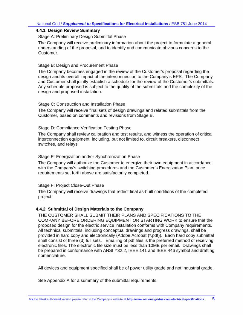
4.4.1 Design Review Summary Stage A: Preliminary Design Submittal Phase
The Company will receive preliminary information about the project to formulate a general understanding of the proposal, and to identify and communicate obvious concerns to the Customer.
Stage B: Design and Procurement Phase
The Company becomes engaged in the review of the Customer’s proposal regarding the design and its overall impact of the interconnection to the Company’s EPS. The Company and Customer shall jointly establish a schedule for the review of the Customer’s submittals. Any schedule proposed is subject to the quality of the submittals and the complexity of the design and proposed installation.
Stage C: Construction and Installation Phase
The Company will receive final sets of design drawings and related submittals from the Customer, based on comments and revisions from Stage B.
Stage D: Compliance Verification Testing Phase
The Company shall review calibration and test results, and witness the operation of critical interconnection equipment, including, but not limited to, circuit breakers, disconnect switches, and relays.
Stage E: Energization and/or Synchronization Phase
The Company will authorize the Customer to energize their own equipment in accordance with the Company’s switching procedures and the Customer’s Energization Plan, once requirements set forth above are satisfactorily completed.
Stage F: Project Close-Out Phase
The Company will receive drawings that reflect final as-built conditions of the completed project.
4.4.2 Submittal of Design Materials to the Company
THE CUSTOMER SHALL SUBMIT THEIR PLANS AND SPECIFICATIONS TO THE COMPANY BEFORE ORDERING EQUIPMENT OR STARTING WORK to ensure that the proposed design for the electric service installation conforms with Company requirements. All technical submittals, including conceptual drawings and progress drawings, shall be provided in hard copy and electronically (Adobe Acrobat (*.pdf)). Each hard copy submittal shall consist of three (3) full sets. Emailing of pdf files is the preferred method of receiving electronic files. The electronic file size must be less than 10MB per email. Drawings shall be prepared in conformance with ANSI Y32.2, IEEE 141 and IEEE 446 symbol and drafting nomenclature.
All devices and equipment specified shall be of power utility grade and not industrial grade.
See Appendix A for a summary of the submittal requirements.
National Grid / Supplement to Specifications for Electrical Installations / ESB 751 June 2014
6 For the latest authorized version please refer to the Company’s website at http://www.nationalgridus.com/electricalspecifications
4.4.3 Schedule
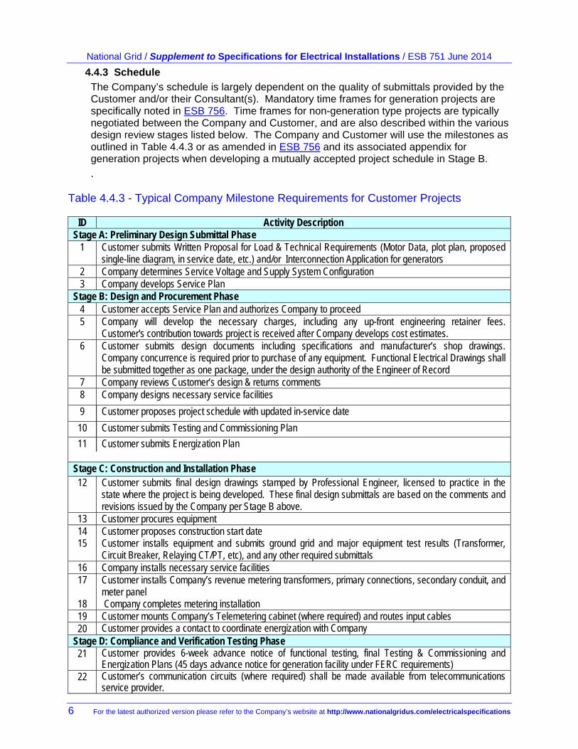
The Company’s schedule is largely dependent on the quality of submittals provided by the Customer and/or their Consultant(s). Mandatory time frames for generation projects are specifically noted in ESB 756. Time frames for non-generation type projects are typically negotiated between the Company and Customer, and are also described within the various design review stages listed below. The Company and Customer will use the milestones as outlined in Table 4.4.3 or as amended in ESB 756 and its associated appendix for generation projects when developing a mutually accepted project schedule in Stage B.
. Table 4.4.3 - Typical Company Milestone Requirements for Customer Projects
ID Activity Description Stage A: Preliminary Design Submittal Phase
1 Customer submits Written Proposal for Load & Technical Requirements (Motor Data, plot plan, proposed single-line diagram, in service date, etc.) and/or Interconnection Application for generators
2 Company determines Service Voltage and Supply System Configuration 3 Company develops Service Plan
Stage B: Design and Procurement Phase 4 Customer accepts Service Plan and authorizes Company to proceed 5 Company will develop the necessary charges, including any up-front engineering retainer fees.
Customer's contribution towards project is received after Company develops cost estimates. 6 Customer submits design documents including specifications and manufacturer’s shop drawings.
Company concurrence is required prior to purchase of any equipment. Functional Electrical Drawings shall be submitted together as one package, under the design authority of the Engineer of Record
7 Company reviews Customer’s design & returns comments 8 Company designs necessary service facilities
9 Customer proposes project schedule with updated in-service date
10 Customer submits Testing and Commissioning Plan
11 Customer submits Energization Plan Stage C: Construction and Installation Phase 12 Customer submits final design drawings stamped by Professional Engineer, licensed to practice in the
state where the project is being developed. These final design submittals are based on the comments and revisions issued by the Company per Stage B above.
13 Customer procures equipment 14 15
Customer proposes construction start date Customer installs equipment and submits ground grid and major equipment test results (Transformer, Circuit Breaker, Relaying CT/PT, etc), and any other required submittals
16 Company installs necessary service facilities 17
18
Customer installs Company’s revenue metering transformers, primary connections, secondary conduit, and meter panel Company completes metering installation
19 Customer mounts Company’s Telemetering cabinet (where required) and routes input cables 20 Customer provides a contact to coordinate energization with Company
Stage D: Compliance and Verification Testing Phase 21 Customer provides 6-week advance notice of functional testing, final Testing & Commissioning and
Energization Plans (45 days advance notice for generation facility under FERC requirements) 22 Customer’s communication circuits (where required) shall be made available from telecommunications
service provider.
National Grid / Supplement to Specifications for Electrical Installations / ESB 751 June 2014
For the latest authorized version please refer to the Company’s website at http://www.nationalgridus.com/electricalspecifications. 7
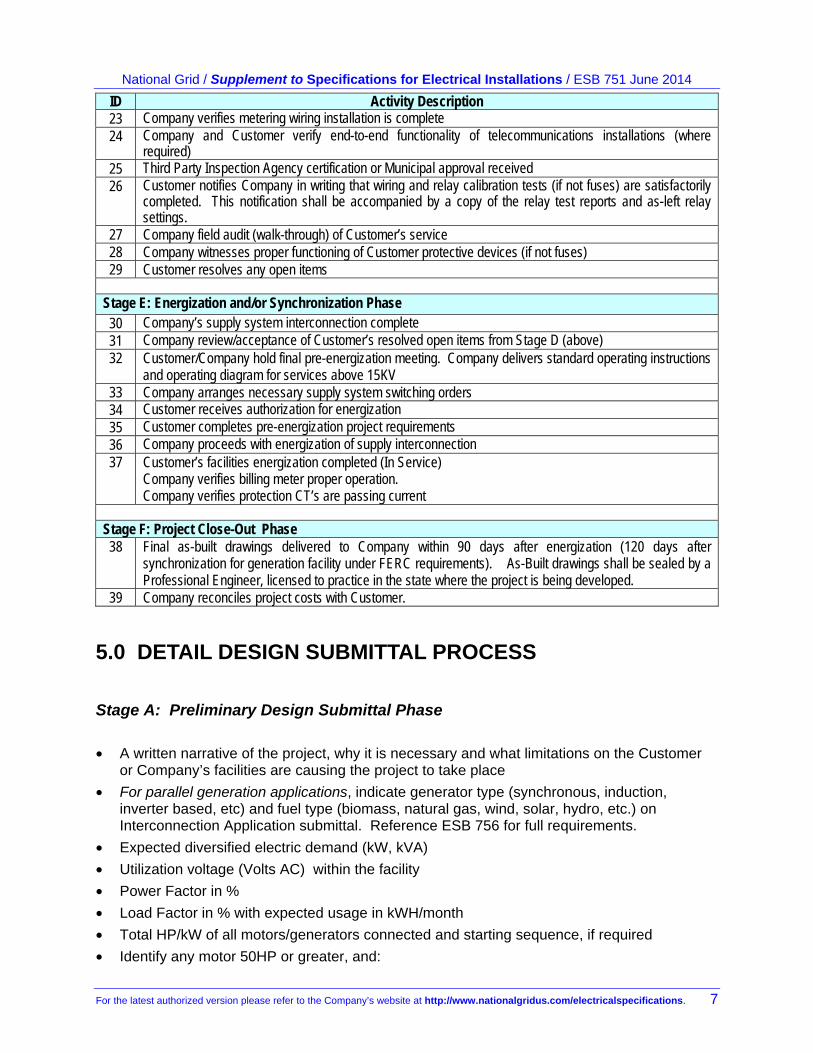
ID Activity Description 23 Company verifies metering wiring installation is complete 24 Company and Customer verify end-to-end functionality of telecommunications installations (where
required) 25 Third Party Inspection Agency certification or Municipal approval received 26 Customer notifies Company in writing that wiring and relay calibration tests (if not fuses) are satisfactorily
completed. This notification shall be accompanied by a copy of the relay test reports and as-left relay settings.
27 Company field audit (walk-through) of Customer’s service 28 Company witnesses proper functioning of Customer protective devices (if not fuses) 29 Customer resolves any open items
Stage E: Energization and/or Synchronization Phase 30 Company’s supply system interconnection complete 31 Company review/acceptance of Customer’s resolved open items from Stage D (above) 32 Customer/Company hold final pre-energization meeting. Company delivers standard operating instructions
and operating diagram for services above 15KV 33 Company arranges necessary supply system switching orders 34 Customer receives authorization for energization 35 Customer completes pre-energization project requirements 36 Company proceeds with energization of supply interconnection 37 Customer’s facilities energization completed (In Service)
Company verifies billing meter proper operation. Company verifies protection CT’s are passing current
Stage F: Project Close-Out Phase 38 Final as-built drawings delivered to Company within 90 days after energization (120 days after
synchronization for generation facility under FERC requirements). As-Built drawings shall be sealed by a Professional Engineer, licensed to practice in the state where the project is being developed.
39 Company reconciles project costs with Customer.
5.0 DETAIL DESIGN SUBMITTAL PROCESS
Stage A: Preliminary Design Submittal Phase
• A written narrative of the project, why it is necessary and what limitations on the Customer or Company’s facilities are causing the project to take place
• For parallel generation applications, indicate generator type (synchronous, induction, inverter based, etc) and fuel type (biomass, natural gas, wind, solar, hydro, etc.) on Interconnection Application submittal. Reference ESB 756 for full requirements.
• Expected diversified electric demand (kW, kVA)
• Utilization voltage (Volts AC) within the facility
• Power Factor in %
• Load Factor in % with expected usage in kWH/month
• Total HP/kW of all motors/generators connected and starting sequence, if required
• Identify any motor 50HP or greater, and:
National Grid / Supplement to Specifications for Electrical Installations / ESB 751 June 2014
8 For the latest authorized version please refer to the Company’s website at http://www.nationalgridus.com/electricalspecifications
o any generator to be connected (HP/kW, Volts AC).
o number of starts per day and number of starts per hour for each motor
o type of motor (induction, synchronous, etc), RPM, Phases, Efficiency, Power Factor, Locked Rotor Current, Nameplate Code Letter
o type of starting to be implemented for any motor 50HP or greater: across-the-line full voltage, or reduced voltage at percent voltage initial start, or soft start. Specifications for motor starter to determine the limits of inrush mitigation.
• The desired electric in-service date for energization
• The desired electric in-service date for:
o full demand; and
o staged incremental demand
• Temporary construction service needs, including:
o Utilization Voltage (Volts AC)
o Demand (KW)
o Date needed
• A proposed single-line diagram of the proposed electric service. The Company reserves the right to determine the main source of protection (i.e. circuit breaker in lieu of fuse) if coordination with the Company’s upstream protective device cannot be achieved.
• Site Plan of the proposed service arrangement, to scale.
Stage B: Design and Procurement Phase The service voltage and the construction type (overhead or underground) have different requirements for the Company’s review. The matrix shown in Appendix A describes the specific requirements for each type of service over 600 Volts. The descriptions below provide guidance on the required nature and content of the submittal.
• Functional Electrical Drawings which shall consist of the Single Line Drawing, AC Elementary Drawings and DC Elementary Drawings, shall be submitted together as one package, under the design authority of the Engineer of Record. Drawings shall be prepared in conformance with ANSI Y32.2, IEEE 141 and IEEE 446 symbol and drafting nomenclature. Reference ESB 750 Section 1.7.2.1.
o Complete Functional Electrical Single Line* detailing all devices up to, and including, the Customer’s secondary bus. Functional Electric Single Line drawing for parallel generator installations shall show the entire system through the electrical generator connection. It shall include: all protective devices including ratings and classes in sufficient detail to show intended operation; all instrument transformers with ratios; power and station service transformers with ratios, kVA, winding configurations, impedances; etc. All Customer interconnection devices, including switches, breakers, fuses, busses and transformers shall be uniformly placarded in accordance with the Company’s nomenclature practices. The Company shall assign these device numbers which aid in communications and coordination during switching operations between the Company and the Customer.
o Electrical AC ELEMENTARY Drawing* (a.k.a. Three Line Diagram) including all equipment shown on the functional electrical single line (see above).
National Grid / Supplement to Specifications for Electrical Installations / ESB 751 June 2014
For the latest authorized version please refer to the Company’s website at http://www.nationalgridus.com/electricalspecifications. 9
o Electrical DC ELEMENTARY Drawing* in sufficient detail to show the functional control operation of the Customer’s equipment. The D.C. elementary schematic diagram shall show, by means of graphic symbols, all devices having any interaction with the tripping function of the protective devices shown on the functional electrical single line (see above). Relay contacts shall always be shown in the de-energized position. Ladder-type diagrams are not acceptable.
• Site Plans* consisting of a large scale drawing with landmarks such as buildings, roads, railroads, environmental concerns, existing Company electrical structures, and the proposed location of the Customer’s service facilities. Where the Customer’s electric service facilities are located within a building, the building plan shall also be included. Proposed location of the Company’s billing meter shall be shown on the site drawings submitted.
• Electrical Assembly* consisting of a detailed plan and profile drawing of the substation, switchgear, wooden or steel structures, in sufficient detail to clearly determine electrical clearances and placement of equipment on each of the structures. Where switchgear is proposed, the electrical assembly drawings will include the manufacturer’s detailed switchgear assembly drawings with plan and profile details for each cubicle, specific to the proposed installation.
• Profile Drawings* consisting of a minimum of two perpendicular cuts of the site plan (see above). Profiles shall be of the substation, switchgear, primary meter pole, or switchgear building, and shall be in sufficient detail to allow for the Company’s determination of electrical and working space clearances. Substation fence heights shall be shown in these profiles.
• Substation Lightning Protection Plan* which shows the location of lightning protection within the substation and the related method of calculations demonstrating the shielding of the Customer’s facilities. Reference ESB 752 for further technical details.
• Protective Device Coordination Study* incorporating a summary list of proposed relay settings and/or fuse curves which show coordination with Customer-owned equipment and Company-owned upstream protection devices. (Note: Settings shall not be shown on drawings.) A settings summary sheet shall be provided, along with the specific relay manufacturer’s setting file.
• Structural and Foundation Drawings* to demonstrate the adequacy of the substation receiving point (take-off structure). The Company will provide the conductor tensions, heights, spacing and angles. These specifications shall be shown on the Customer’s drawings.
• Ground Grid Analysis and Ground Grid Drawing* in compliance with IEEE 80 and 81, shall include soil resistivity test results and ground grid design for safe step and touch voltages and acceptable ground potential rise. The ground grid design shall identify the target ground grid resistance used as the basis of calculation of the step voltage, touch voltage and GPR. There shall be a separate ground grid drawing, in plan view, to scale, showing the location of ground conductors, ground rods, and connection to above grade metallic structures.
• Meter, Control Cable, and Power Conduit Drawings* including location, depth of burial, materials, and routing. These drawings shall be to scale. These drawings shall include (where applicable), handhole and manhole locations and details per the Company’s ESB 759B. Note: The Company shall provide and install secondary wiring from the Company’s metering transformers to the Company’s billing meter in Customer provided and Customer installed raceway as directed by the Company.
• Control House Layout in plan view and profile.
Relay Panel Drawings including test switch designations and locations. This drawing shall depict the front view of the devices as they are to be located on the panel. All devices shall have a nameplate labels, consistent with the three line and DC elementary drawings.
National Grid / Supplement to Specifications for Electrical Installations / ESB 751 June 2014
10 For the latest authorized version please refer to the Company’s website at http://www.nationalgridus.com/electricalspecifications
Detailed Manufacturer’s Cut Sheets of major components (i.e., breakers, fuses, disconnect switches, transformers, PT/CT’s, arresters, etc.) shown on the electrical single line drawing. The Company shall specify which equipment shall be submitted for review.
o Transformer Manufacturer’s Cut Sheets shall include nameplate, test reports and outline drawings including winding configurations, taps, BIL ratings, impedances, CT test reports, etc.
o Main Disconnect Switch Manufacturer’s Cut Sheets shall include nameplate, ratings, certifications, conductor tension limits, and ice break capabilities.
o Circuit Breaker Manufacturer’s Cut Sheets shall include BIL ratings, continuous symmetrical and asymmetrical interrupting ratings, control voltage source, CT test reports, related nameplate data, etc.
o Circuit Breaker Tripping Energy Source Cut Sheets shall identify type of energy source used (battery, capacitor, UPS, etc.). The source shall be shown to be adequate to trip the breaker(s) under low voltage and no voltage conditions.
o Fuse Manufacturer’s Cut Sheets shall include TCC curve number with minimum melt and total clear curves, symmetrical and asymmetrical interrupting ratings, and ratings of the fuse cut-outs.
o Relay Manufacturer’s full specified model number and firmware version. Relay operating manual may be required if requested by the Company.
o Generator Manufacturer’s Specifications: shall include nameplate information, a complete set of engine specifications, generator specifications and operating characteristics as well as control system data (for rotating machines), DC input and AC output specifications (including firmware versions) and testing certifications for inverter based systems.
• Telecommunications: if required, as determined by the Company, shall include wiring diagrams, equipment drawings, and circuit assignments as coordinated with the Company.
• Maintenance Plan: which identifies the specific equipment to be maintained and the maintenance schedule. See the Company’s ESB 755 for guidance.
• Sequence of Operations: required for all generation related interconnections, and services which involve automatic bus transfer. A written document which explains how automated switching will occur based on planned and unplanned outage events, and the automatic restoration back to original conditions. Correct breaker, bus, transformer, and disconnect nomenclature shall be referenced throughout this procedure, and shall be consistent with the submitted single line drawing.
• Testing and Commissioning Plan (TCP): shall include the procedural steps for testing and functional verification of the Customer’s relay, breakers, interlocking schemes, and related protection devices. The Company has an interest in witnessing portions of the overall test specific to those devices which interconnect to the Company’s EPS. The Company reserves the right to modify the testing procedure as necessary to ensure the integrity of the Company’s EPS. The individual relay test plan does not need to be submitted at this time. However, during witness testing (see Section 6.1.3), the Company will require the test plan to be made available, and, the Company reserves the right to modify the test plan as necessary.
• Energization Plan: Refer to Section 7.3 of this Bulletin for specific details related to the submittal of the Energization Plan prior to energization.
* The Company requires these engineered submittals to be sealed by the Customer’s retained Design Professional.
National Grid / Supplement to Specifications for Electrical Installations / ESB 751 June 2014
For the latest authorized version please refer to the Company’s website at http://www.nationalgridus.com/electricalspecifications. 11
The Stage B review typically takes the Company 4 to 6 weeks on average, to complete, after all required submittals are received by the Company. The Company’s review is an iterative process between the Company and the Customer’s Design Professional. The complexity of the design and the high voltage expertise of the Customer’s Design Professional can adjust this time frame accordingly. The Company’s other project commitments at peak times can also extend the time to complete this review. The Customer shall submit final for-construction design drawings for acceptance by the Company, per Stage B (above), prior to ordering equipment or starting construction. Reference ESB 750 Section 1.7.2.1.
Stage C: Construction and Installation Phase Three (3) paper copies and an electronic media file, in pdf format, of the final “Final/For Construction” submittals, shall be furnished to the Company. These “Final/For Construction” submittals shall include all changes from the Stage B review. These submittals shall be sealed by the Customer’s retained Design Professional as indicated above in Stage B. The Company shall schedule various site visits during construction as necessary, depending on the complexity of the project. Typical site visits include, but are not limited to, observation of the initial site preparation, installation of ground grid, equipment bonding, and a final, pre-energization walk-through.
6.0 COMPLIANCE AND VERIFICATION
Stage D: Compliance and Verification Testing Phase
The Company has an interest in maintaining reliability of the Electric Power System to which the Customer is interconnected. To this end, and prior to energization, the Company shall observe and verify that the Customer’s facility has been constructed, and is functioning in accordance with the Company-accepted design.
6.1 CUSTOMER NOTIFICATION OF SATISFACTORY COMPLETION OF CONSTRUCTION
Six (6) weeks prior to the Company’s field audit, the Interconnection Customer shall provide written documentation of satisfactory construction completion. This shall include the contractor’s functional testing schedule and Testing and Commissioning Plan for the protective relay systems.
6.1.1 Required Testing Documentation
The Company will require various test reports prior to the Company’s on-site witness testing:
• Transformer Acceptance Test Report based on actual on-site testing
• Relay settings and relay functional testing results (per coordination study accepted by Company)
National Grid / Supplement to Specifications for Electrical Installations / ESB 751 June 2014
12 For the latest authorized version please refer to the Company’s website at http://www.nationalgridus.com/electricalspecifications
• CT ratio and saturation test reports
• PT test reports
• Ground grid resistance test
• Circuit breaker acceptance test (where circuit breaker is used as main overcurrent protective device)
• Verification of adequacy of DC battery supply
• A letter, written by the Customer or their assigned agent, indicating the protection and control scheme has been functionally tested in accordance with the Customer’s submitted design as accepted by the Company. Typically, the Customer’s assigned relay technician will test the entire control schematic, highlighting the various portions of the control circuits on the drawings as they are tested. This procedure needs to be completed prior to the Company’s witness testing.
6.1.2 Customer’s Testing and Commissioning Plan Requirements
The Customer’s Testing and Commissioning Plan shall include, but is not limited to:
1. A step-by-step process which proves the operation of the key interconnection protective devices, including relays, breakers, and switches
2. Systems and Components to be “Witness Tested”.
The injection of analog inputs to the microprocessor relays to actuate the output, and to see the correct device operate. “Jumpering” of input or output contacts will not be accepted as verification of device operation.
Verification of phase angles between sources and relay inputs
6.1.3 Relay Witness Testing
The Company, at its own discretion, shall witness the operation of key Customer owned protection devices and schemes to ensure compliance and verification with the design documents previously approved by the Company. The Customer’s relay technician shall have the knowledge and appropriate equipment available to work through the Testing and Commissioning Plan (see above) as necessary.
6.1.4 Company’s Field Audit
The Company shall make a final walk-through field audit of the substation to confirm the construction of the substation is in substantial conformance with the Company accepted design submittals. The Company will also verify live part clearances, verify final grounding attachments, observe related safety signs and fencing, and ensure the Company has access to the substation or main disconnect device, as a condition of acceptance.
During the Company’s Field Audit, the Company shall verify the permanently installed placards on the specific devices, as required by the Company and as outlined by Stage B (see Complete Functional Electrical Single Line). The placards shall be clearly visible to operators.
6.1.5 Electrical Inspection by Code Enforcement Authority
The design and construction of the Customer’s substation shall be in accordance with the requirements of the National Electrical Code, unless the Customer is considered a “supply” company, and provides such evidence to the Company of this status. Therefore, the Customer shall provide evidence of an electrical inspection, performed by the Authority Having
National Grid / Supplement to Specifications for Electrical Installations / ESB 751 June 2014
For the latest authorized version please refer to the Company’s website at http://www.nationalgridus.com/electricalspecifications. 13
Jurisdiction or their assigned agent. The assigned agent, consisting of a third party underwriting agency must be approved within National Grid’s electric service territory.
NOTE: The Customer’s third party or municipal electrical inspection approval certificate shall be submitted to the Company prior to energization, preferably before or at the time of the Company’s on-site field audit of the Customer’s station.
6.1.6 Customer Operating Agreement and Company Operating Diagram National Grid requires a list of 24 hour emergency contacts from the Customer, once their facility is interconnected to the National Grid transmission system. During the operation of the transmission system, National Grid will occasionally need to contact the Customer for information, discussion, switching, or emergency reasons. The Customer shall provide a list of the primary and alternate contact personnel in the order which National Grid should attempt to contact them. The information required is:
1. Name 2. Business Address 3. Business Telephone Number 4. Mobile Telephone Number 5. Home Telephone Number 6. E-mail Address
The Company will issue the Customer Operating Agreement and a Company Operating Diagram specific to the Customer installation. The Operating Agreement will include key Company contact numbers for normal and emergency operation, along with general information for system operations. The Company issued Operating Diagram includes the Customer’s 24 hour emergency contact information, per above, which will be on file at the Company’s Power Control Center. This information should be updated, as necessary, by the Customer to ensure appropriate Customer contact information is maintained. Normally, National Grid would not attempt to contact the Customer’s representatives at home or after normal business hours unless there is an emergency.
6.1.7 Company’s Right to Operate
The Company reserves the right to operate, and if necessary tag the Customer’s main disconnecting device (and generator disconnecting device) as necessary, for the protection of the EPS, the Company’s employees and the general public.
7.0 ENERGIZATION AND/OR SYNCHRONIZATION
Stage E: Energization and Synchronization Phase
7.1 PREREQUISITES Once the Company has determined that all requirements in Stage D, Compliance and Verification have been met, the Company will authorize energization of the Customer’s facility in accordance with the accepted Testing and Commissioning Plan and the Company’s standard operating procedures.
National Grid / Supplement to Specifications for Electrical Installations / ESB 751 June 2014
14 For the latest authorized version please refer to the Company’s website at http://www.nationalgridus.com/electricalspecifications
7.2 AUTHORIZATIONS The Company’s Control Centers require advance notice prior to energization. Two (2) weeks advance notice is required when 115kV system interruptions are to be scheduled and typically one (1) week for 23kV, 34.5kV, and 46kV systems. Three (3) business days advance notice are required for distribution circuits operating less than 15kV.
7.3 ENERGIZATION PLAN
7.3.1 Energization Coordinator
The Customer shall designate an Energization Coordinator, and prepare and submit an Energization Plan to the Company for review and comment.
7.3.2 Energization Plan Development and Execution
1. The Energization Plan is a step by step switching process which identifies the order in which each device will be operated to energize the Customer’s facility. The Energization Plan shall comply with the Company’s ESB 755 and NESC Section 44. The Energization Plan shall include but not be limited to, such items as:
• Steps for the removal of grounds and releasing of corresponding clearances;
• Switching control procedures;
• Required phasing and synchronization tests; and
• Load and operational tests required to place the apparatus or systems on line without risk to the electrical infrastructure.
• Sequence of Operations including steps for all normal and abnormal modes of operation and control.
2. The Energization Plan shall be executed upon meeting the following minimum pre-energization requirements for the Customer’s station:
• The Company requires satisfactory completion of the items listed in Section 5.0 above.
• The Customer’s outdoor substation physical protection shall be in place in accordance with applicable codes and local requirements, i.e., fence, gates, signs, locks, grounding system in accordance with Section 5.1.4 above.
• The Customer’s standard nomenclature will be in place, in the form of tags and/or stickers, for the Customer-owned substation which will be consistent with the operating diagram and operating agreement as listed in Section 5.1.4 above.
• The Customer and Company shall hold final pre-energization meeting. Company delivers standard operating instructions and operating diagram for services above 15KV during this meeting. The Customer’s Energization Coordinator shall be at this meeting.
7.3.3 Synchronization
1. Before generation can be synchronized with the Company’s power system, the following shall be satisfactory to the Company:
• Special equipment as required, for necessary operating control, monitoring, and security on the Company’s system, shall be operable per Section 5.0 above.
National Grid / Supplement to Specifications for Electrical Installations / ESB 751 June 2014
For the latest authorized version please refer to the Company’s website at http://www.nationalgridus.com/electricalspecifications. 15
• The Company’s verification testing of the Customer’s generation control equipment shall be completed per Section 5.0 above.
• The Company shall verify the relay testing of the designated devices before the generation is permitted to parallel with the Company’s system per Section 5.0 above.
8.0 PROJECT CLOSE OUT
Stage F: Project Closeout Phase As-built documentation is required at the end of the design process. Within 90 days of energization (or within 120 days of synchronization for a generation facility under FERC requirements), the Customer shall submit a full set of the drawings and documents in Stages B and C above, to ensure the Company’s operating documents are complete for proper supply system operation. The as-built submittal shall include any deviations from the “Final/For Construction” drawings and shall consist of three (3) full sets of hard copy drawings and documents along with an electronic version per Section 4.4.2, above. Any deviations from the original “Final/For Construction” drawings shall be bubble-clouded for ease of identification. These as-built drawings shall be sealed by the Customer’s Design Professional in accordance with the requirements of Section 4.4.4 (Stage B) above.
The Company will reconcile any outstanding charges, either credit or debit, with the Customer as part of this phase.
9.0 PERIODIC VERIFICATION In addition to the requirements as set forth by National Grid’s Electric Service Bulletin 755, “Operation and Maintenance Requirements for Services Above 600 Volts”, the following periodic verification requirements are expected:
1. The Company reserves the right to examine the Customer’s facility and perform or witness testing of any equipment or devices where both parties have a mutual interest at any time.
2. The Company reserves the right to periodically check the Customer’s designated protective devices. A check will consist of a visual/mechanical examination of the designated required devices, seals (where applicable) and associated wiring. Where seals exist and if broken, the protective devices shall be recalibrated, tested and re-sealed by the Company.
3. The Customer or Generator-owner shall maintain an operating log at their facility indicating changes in operating status (available or unavailable generation, maintenance outages, trip indications or other unusual conditions found upon inspection). For generators which are “block-loaded” to a specific kW level, changes in this setting shall also be logged. This log shall be made available to the Company upon request.
4. The Company reserves the right to inspect the Customer or Generator-owner facilities and maintenance records to verify the correct operation of all equipment which affects Company operation and safety.
National Grid / Supplement to Specifications for Electrical Installations / ESB 751 June 2014
16 For the latest authorized version please refer to the Company’s website at http://www.nationalgridus.com/electricalspecifications
5. Arrangements shall be provided so that authorized Company employees may have access to the Customer’s substation, switching facilities and metering at any time and without delay. See Section 5.1.7.
10.0 REVISION HISTORY Version Date Description of Revision 0.0 1/6/14 DRAFT 1.0 6/3/14 FINAL
National Grid / Supplement to Specifications for Electrical Installations / ESB 751 June 2014
For the latest authorized version please refer to the Company’s website at http://www.nationalgridus.com/electricalspecifications. 17
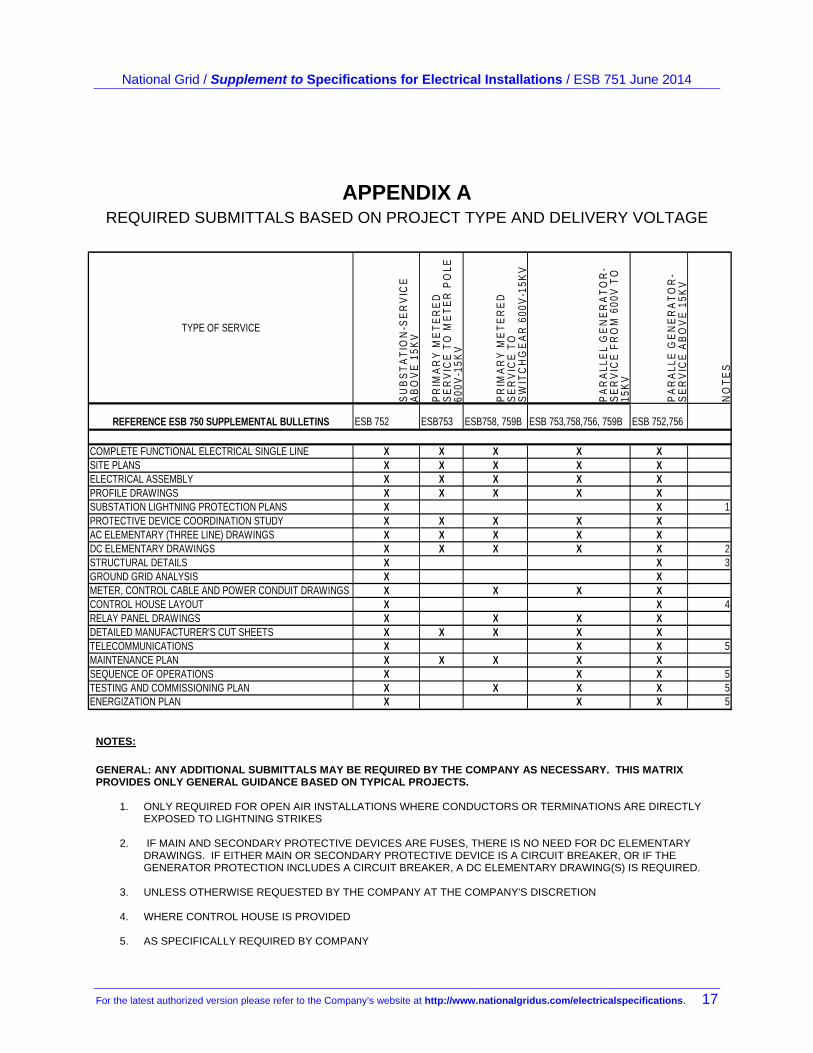
APPENDIX A REQUIRED SUBMITTALS BASED ON PROJECT TYPE AND DELIVERY VOLTAGE
TYPE OF SERVICE
SU
BS
TA
TIO
N-S
ER
VIC
E
AB
OV
E 1
5KV
PR
IMA
RY
ME
TE
RE
D
SE
RV
ICE
TO
ME
TE
R P
OLE
60
0V-1
5KV
PR
IMA
RY
ME
TE
RE
D
SE
RV
ICE
TO
S
WIT
CH
GE
AR
600
V-1
5KV
PA
RA
LLE
L G
EN
ER
AT
OR
-S
ER
VIC
E F
RO
M 6
00V
TO
15
KV
PA
RA
LLE
GE
NE
RA
TO
R-
SE
RV
ICE
AB
OV
E 1
5KV
NO
TE
S
REFERENCE ESB 750 SUPPLEMENTAL BULLETINS ESB 752 ESB753 ESB758, 759B ESB 753,758,756, 759B ESB 752,756 COMPLETE FUNCTIONAL ELECTRICAL SINGLE LINE X X X X XSITE PLANS X X X X XELECTRICAL ASSEMBLY X X X X XPROFILE DRAWINGS X X X X XSUBSTATION LIGHTNING PROTECTION PLANS X X 1PROTECTIVE DEVICE COORDINATION STUDY X X X X XAC ELEMENTARY (THREE LINE) DRAWINGS X X X X XDC ELEMENTARY DRAWINGS X X X X X 2STRUCTURAL DETAILS X X 3GROUND GRID ANALYSIS X XMETER, CONTROL CABLE AND POWER CONDUIT DRAWINGS X X X XCONTROL HOUSE LAYOUT X X 4RELAY PANEL DRAWINGS X X X X DETAILED MANUFACTURER'S CUT SHEETS X X X X XTELECOMMUNICATIONS X X X 5MAINTENANCE PLAN X X X X X SEQUENCE OF OPERATIONS X X X 5TESTING AND COMMISSIONING PLAN X X X X 5ENERGIZATION PLAN X X X 5
NOTES:
GENERAL: ANY ADDITIONAL SUBMITTALS MAY BE REQUIRED BY THE COMPANY AS NECESSARY. THIS MATRIX PROVIDES ONLY GENERAL GUIDANCE BASED ON TYPICAL PROJECTS.
1. ONLY REQUIRED FOR OPEN AIR INSTALLATIONS WHERE CONDUCTORS OR TERMINATIONS ARE DIRECTLY EXPOSED TO LIGHTNING STRIKES
2. IF MAIN AND SECONDARY PROTECTIVE DEVICES ARE FUSES, THERE IS NO NEED FOR DC ELEMENTARY
DRAWINGS. IF EITHER MAIN OR SECONDARY PROTECTIVE DEVICE IS A CIRCUIT BREAKER, OR IF THE GENERATOR PROTECTION INCLUDES A CIRCUIT BREAKER, A DC ELEMENTARY DRAWING(S) IS REQUIRED.
3. UNLESS OTHERWISE REQUESTED BY THE COMPANY AT THE COMPANY'S DISCRETION
4. WHERE CONTROL HOUSE IS PROVIDED
5. AS SPECIFICALLY REQUIRED BY COMPANY