Embed Size (px)
Citation preview
Crestline® Dampening System
INSTALLATION INSTRUCTIONS
Townsend T-51® Color Head ForA.B. Dick 360
X88-51Rev-A01/2001
GENERAL INFORMATION
Accel Graphic Systems provides parts and service through itsauthorized distributors and dealers. Therefore, all requests forparts and service should be directed to your local dealer.
The philosophy of Accel Graphic Systems is to continually improveall of its products. Written notices of changes and improvementsare sent to Accel Graphic System's Dealers.
If the operating characteristics or the appearance of your productdiffers from those described in this manual, please contact yourlocal Accel Graphic System's Dealer for updated information andassistance.
Always update your dampener when improvements are madeavailable, especially those related to safety.
YOUR AUTHORIZED CRESTLINE® DEALER IS:
THE SERIAL NUMBER OF YOURCRESTLINE® DAMPENER(S) IS:
ATTENTIONCRESTLINE®
DAMPENEROWNER!
2
SAFETYINFORMATION
FOR YOUR SAFETY, DO NOT DISENGAGE OR REMOVEANY GUARDS FROM THE CRESTLINE® DAMPENER. THEDAMPENER CONTAINS SOME INWARD ROTATINGROLLER NIPS THAT CAN CAUSE INJURY IF LEFTUNGUARDED.
GENERAL INFORMATION
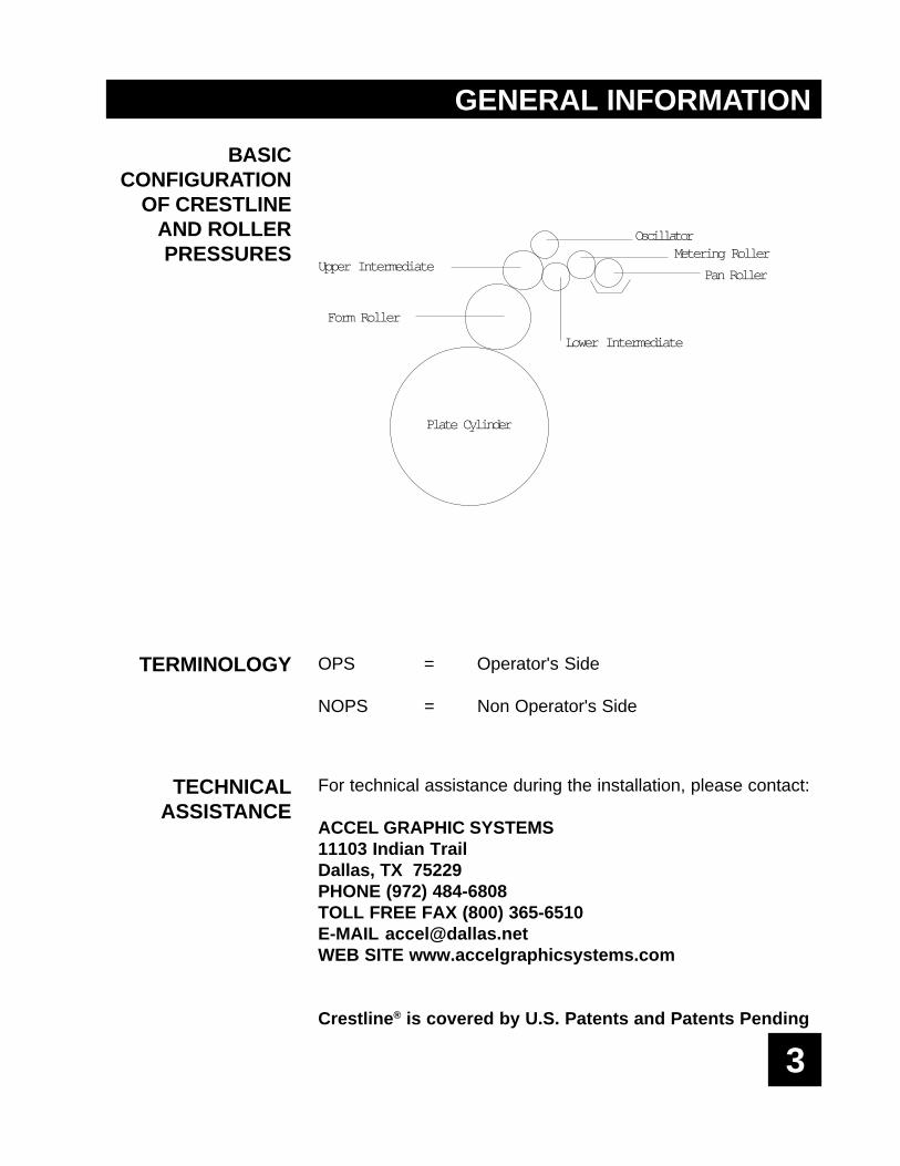
BASICCONFIGURATION
OF CRESTLINEAND ROLLERPRESSURES
TERMINOLOGY
TECHNICALASSISTANCE
OPS = Operator's Side
NOPS = Non Operator's Side
For technical assistance during the installation, please contact:
ACCEL GRAPHIC SYSTEMS11103 Indian TrailDallas, TX 75229PHONE (972) 484-6808TOLL FREE FAX (800) 365-6510E-MAIL [email protected] SITE www.accelgraphicsystems.com
Crestline® is covered by U.S. Patents and Patents Pending
3
Plate Cylinder
Pan Roller
Metering Roller
Form Roller
Lower Intermediate
Upper Intermediate
Oscillator
GENERAL INFORMATION
REQUIRED TOOLSFOR
REMOVAL OF OLDDAMPENER AND
INSTALLATION OFCRESTLINE®
4
1. Slotted Screwdriver
2. 7/16" Open End Wrench
3. Snap Ring Tool
4. 1/8" Allen Wrench
5. 5/32" Allen Wrench
6. 9/64" Allen Wrench
7. 3/16" Allen Wrench
8. 3/32" Allen Wrench
9. Hammer
GENERAL INFORMATION
The remainder of this installation manual is divided into 6 majorsections. They are:
SECTION STARTING PAGE
DISASSEMBLY Page 7
INSTALLATION Page 19
FINAL ADJUSTMENTS Page 33
BASIC OPERATION Page 36
CLEANING & MAINTENANCE Page 37
PARTS LISTINGS Page 39
5
66
77
1
2
3
DISASSEMBLY
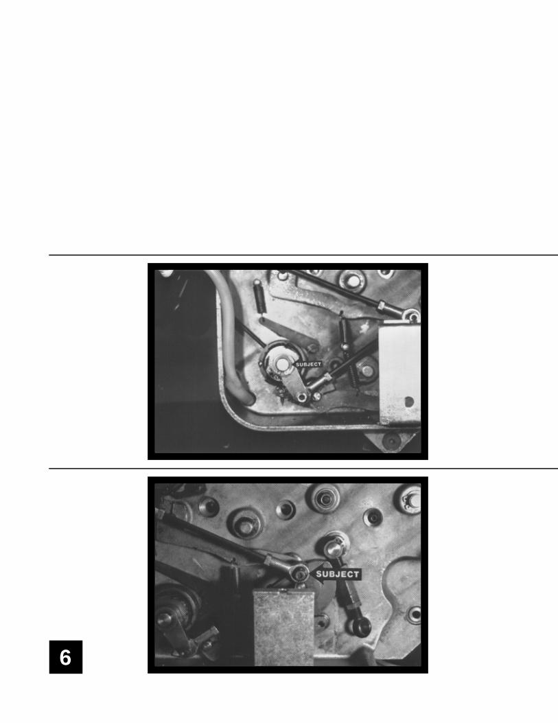
Remove water filler assembly and save for reinstallation.Remove snap ring from pan roller ratchet assembly (subjectarrow).
Remove water pan roller connecting link by removing 2 allenhead cap screws (subject arrow). Reconnect ink fountain rollerlink in original position. Use spacer provided to take the place ofthe water pan roller link removed in previous step.
NOTE: It is possible to position ink fountain roller link in thewrong position when reconnecting. Please observe photo forproper connection.
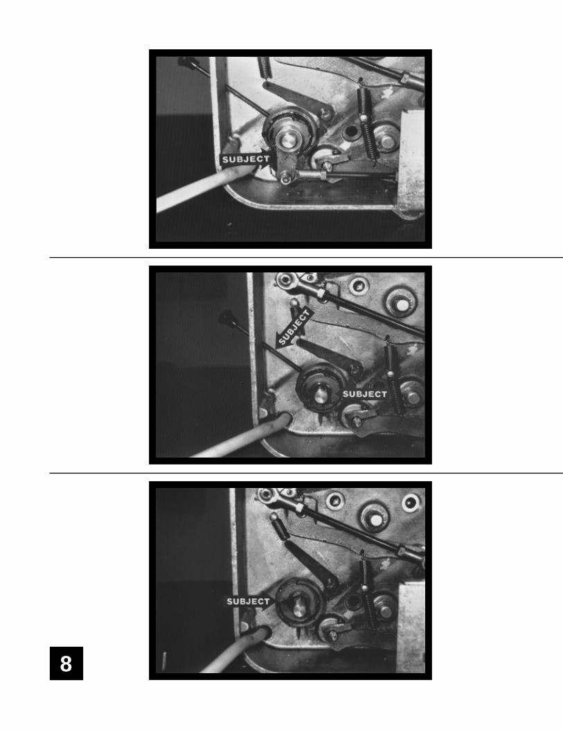
Remove water form, plastic oscillator and water ductor from T-head. Remove side covers and both frames. Disconnect waterhose and remove water pan.
8
9
4
5
6
DISASSEMBLY
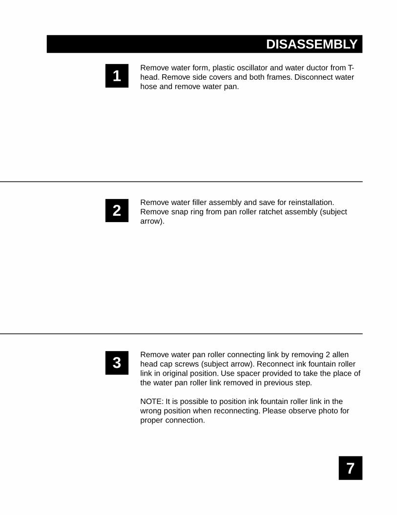
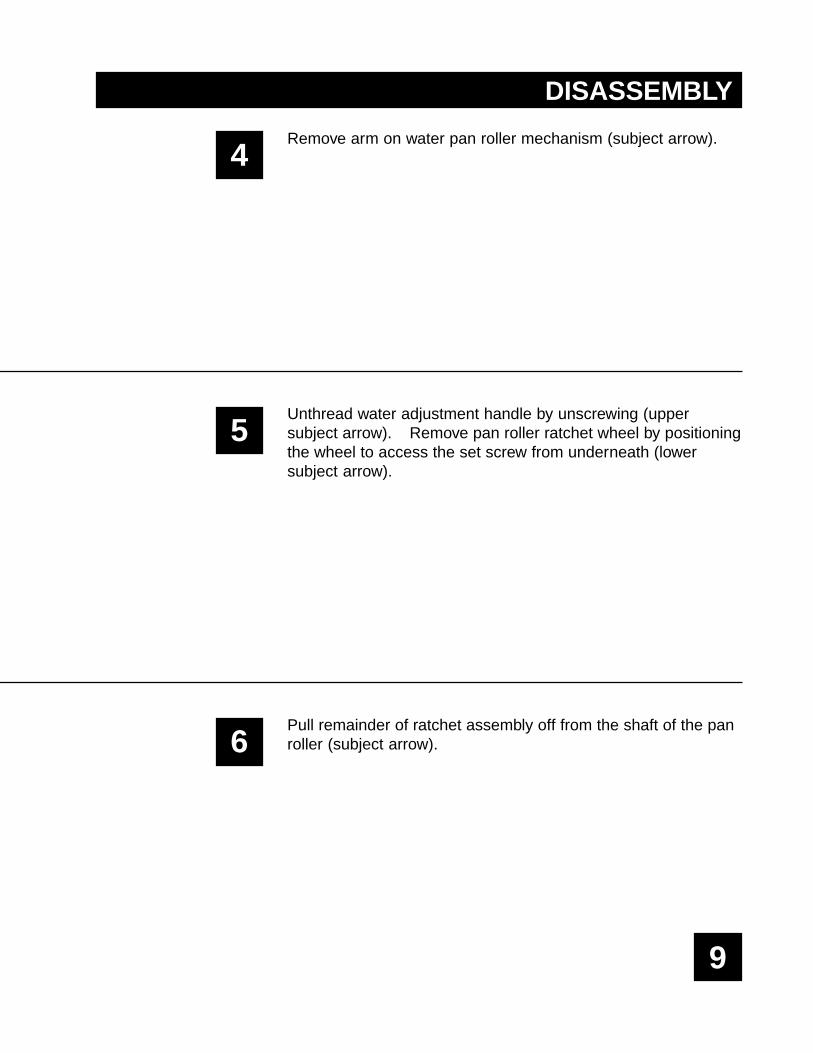
Remove arm on water pan roller mechanism (subject arrow).
Unthread water adjustment handle by unscrewing (uppersubject arrow). Remove pan roller ratchet wheel by positioningthe wheel to access the set screw from underneath (lowersubject arrow).
Pull remainder of ratchet assembly off from the shaft of the panroller (subject arrow).
10
11
7
8
9
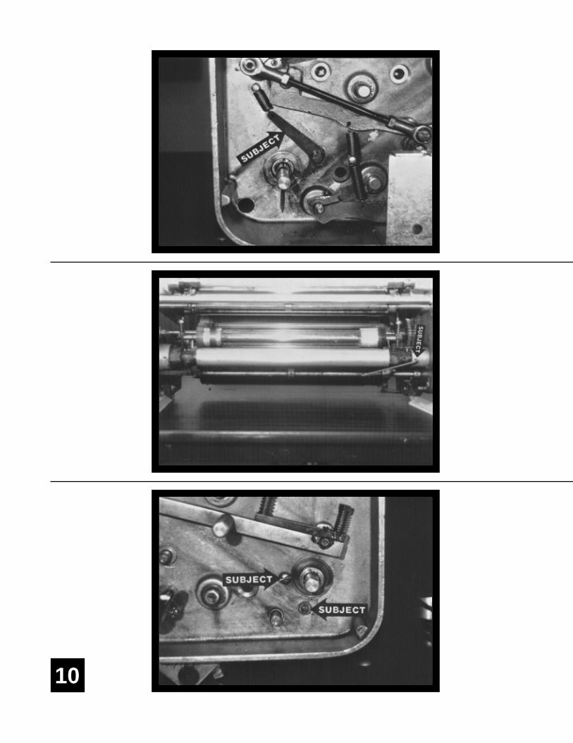
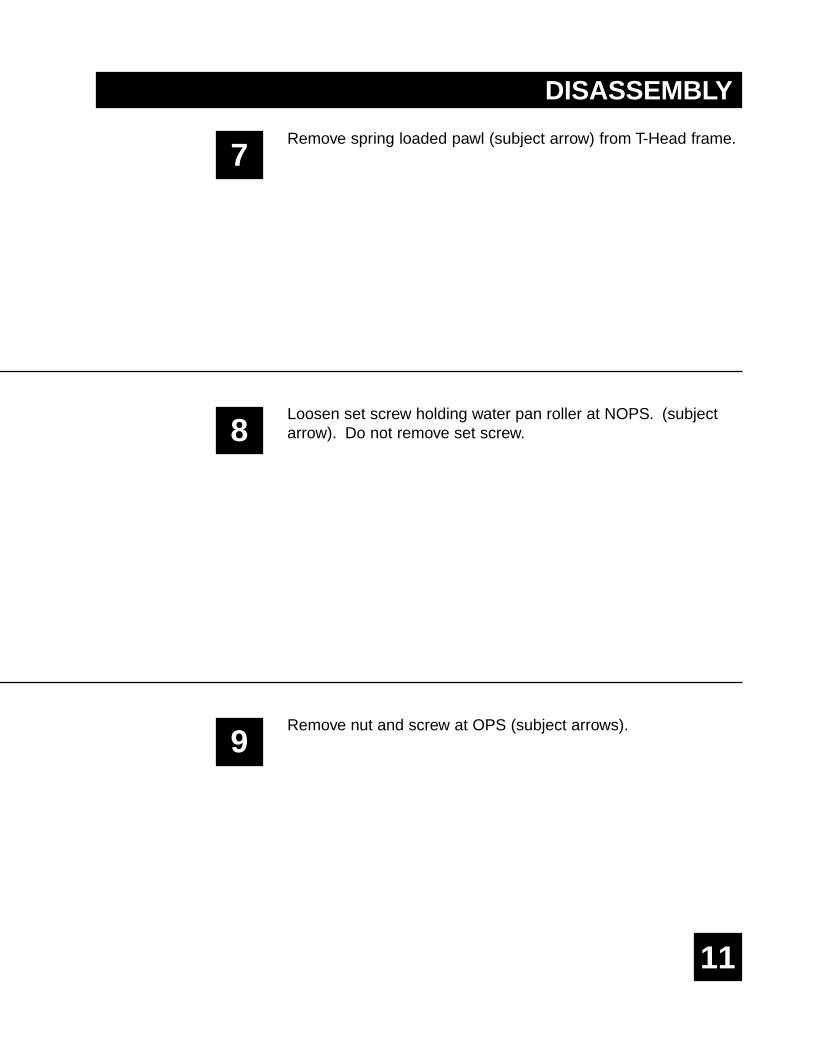
DISASSEMBLY
Remove spring loaded pawl (subject arrow) from T-Head frame.
Loosen set screw holding water pan roller at NOPS. (subjectarrow). Do not remove set screw.
Remove nut and screw at OPS (subject arrows).
12
13
10
11
12
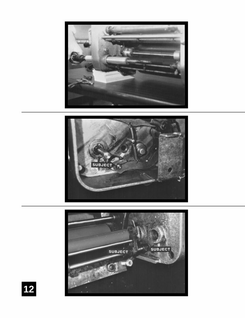
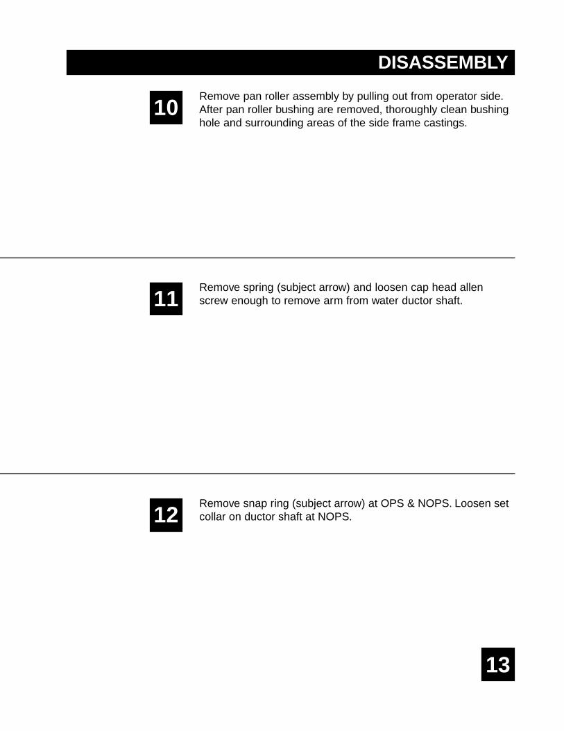
DISASSEMBLY
Remove pan roller assembly by pulling out from operator side.After pan roller bushing are removed, thoroughly clean bushinghole and surrounding areas of the side frame castings.
Remove spring (subject arrow) and loosen cap head allenscrew enough to remove arm from water ductor shaft.
Remove snap ring (subject arrow) at OPS & NOPS. Loosen setcollar on ductor shaft at NOPS.
14
15
13
14
15
DISASSEMBLY
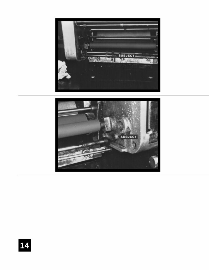
Shift brass bracket from NOPS (subject arrow) towards the OPSas shown.
Remove water ductor bushing on NOPS using punch provided(subject arrow). Punch the bushing from the outside in.
Shift ductor bracket back towards NOPS to remove from thepress.
16
17
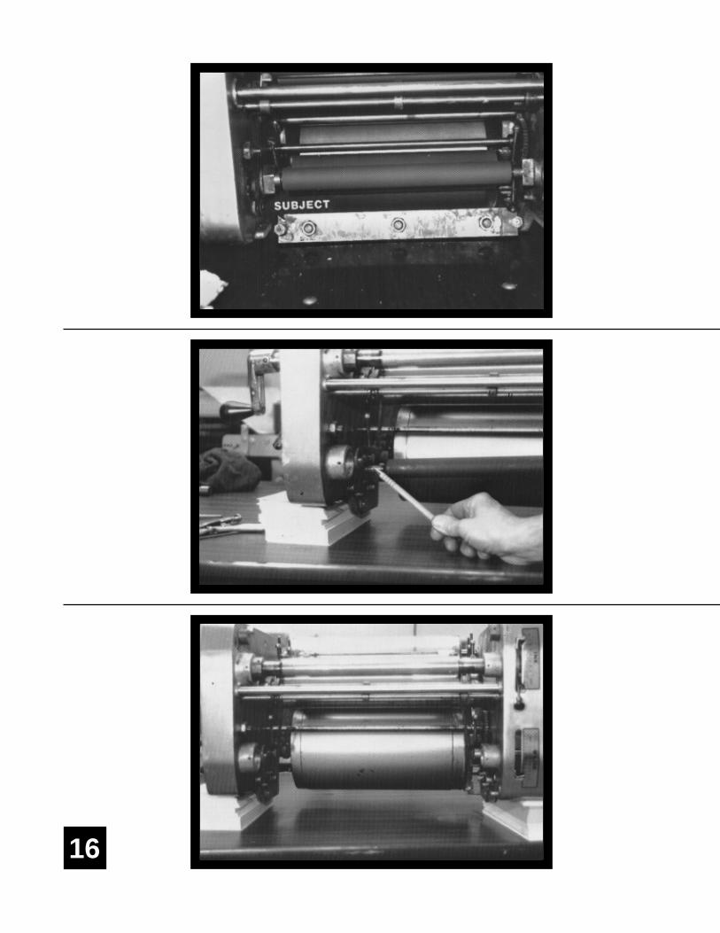
Knock out OPS water ductor bushing (subject arrow).
Remove water transfer roller by loosening the set screw on theOPS only of the side frame casting. Slide ball bearing housingtowards the outside OPS frame. This will allow you to removethe roller.
This is how the T-Head should look after everything is removed.
YOU ARE NOW READY TO INSTALL CRESTLINE®
16
17
18
DISASSEMBLY
18
19
1
2
3
INSTALLATION
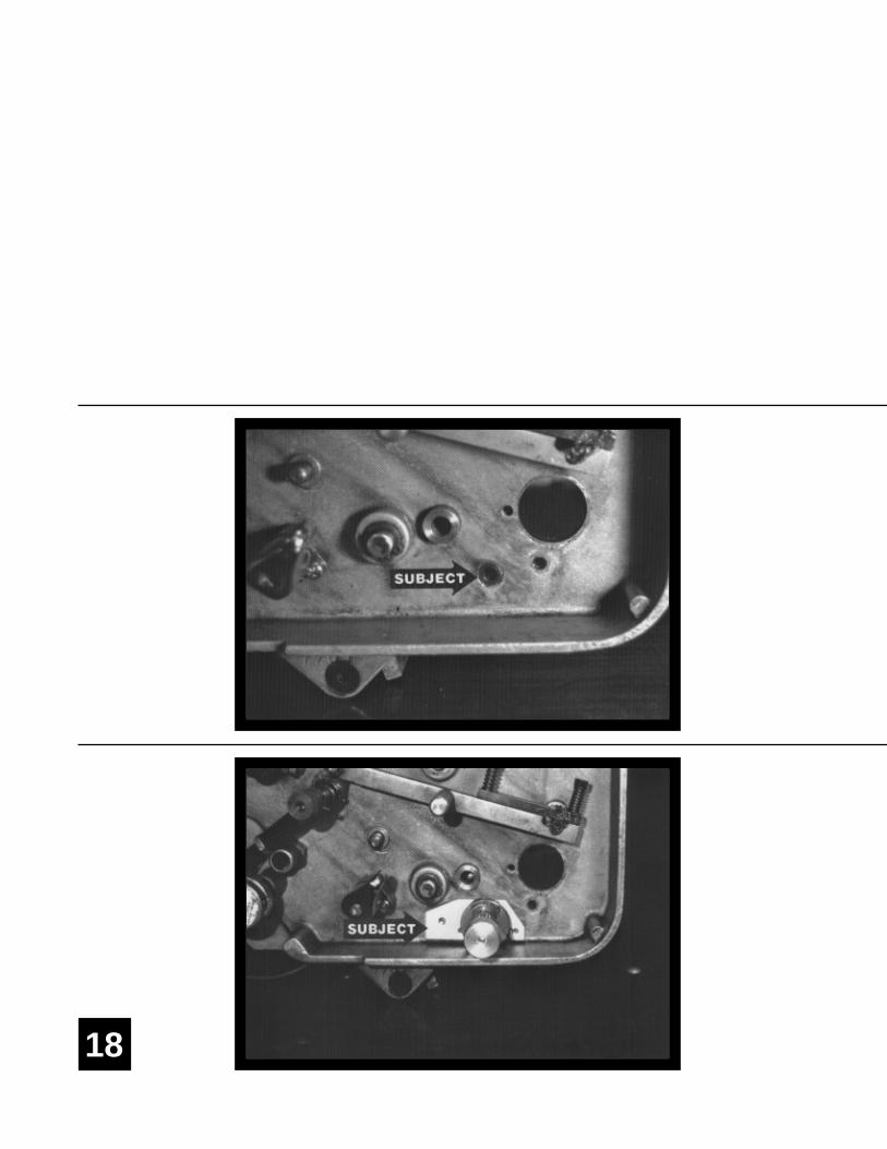
Replace the existing form and transfer rollers in the TownsendHead with the new ones provided with the dampener. Make surethe transfer roller is centered relative to the form roller beforeretightening the set screws in the bearing housings.
Insert spool in hole at OPS (subject arrow).
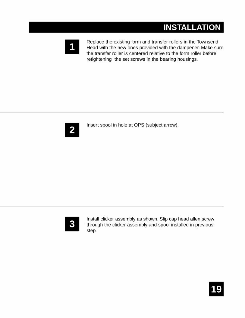
Install clicker assembly as shown. Slip cap head allen screwthrough the clicker assembly and spool installed in previousstep.
20
21
4
5
6
INSTALLATION
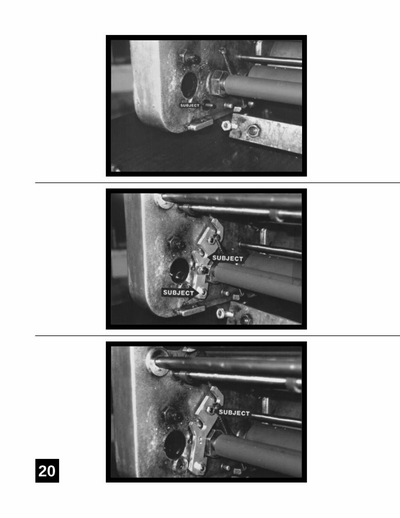
Install black washer on inside of ratchet mechanism bolt atOPS (subject arrow).
Install OPS metering & oscillator bracket (upper subject arrow).OPS bracket has small clearance hole. Put nut on bolt (lowersubject arrow), push the bracket all the way against transferroller casting and tighten thoroughly.
There is a small radius on the outside of the frame casting thatcan cause the clicker assembly to twist. If it helps, insert 2-3pieces of chip board between the bottom of the clicker plateassembly and horizontal portion of frame casting beforetightening nut.
Adjust set screw (subject arrow) until it just touches the T-headcasting to hold the bracket in position. DO NOT applyunnecessary pressure and cause hanger to warp. Reinstall locknuts and retighten.
22
23
7
8
9
INSTALLATION
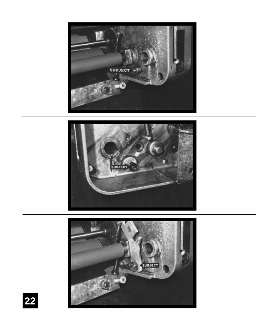
Insert flanged spool (flange to inside) into hole that previouslycontained the water ductor shaft bushing on NOPS.
Install bolt & washer at NOPS (subject arrow) to hold flangedspool in place. Bolt will be inserted from outside the T-Headframe.
Install eccentric & bracket at NOPS (subject arrow). Positioneccentric so the high side of the lobe faces directly out of themachine. There will be a yellow dot denoting this side of thecam. The flat side of the eccentric nearest the yellow dot will beapproximately parallel to the edge of the hanger bracket. Makesure the hanger bracket is pushed all the way forward againstthe casting and snug bolt with wrench. Adjust set screw in top ofbracket as in step 6.
24
25
10
11
12
INSTALLATION
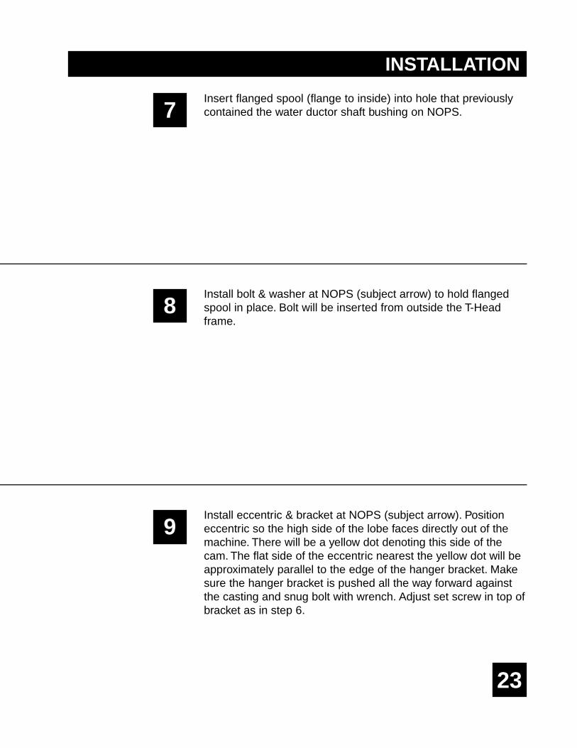
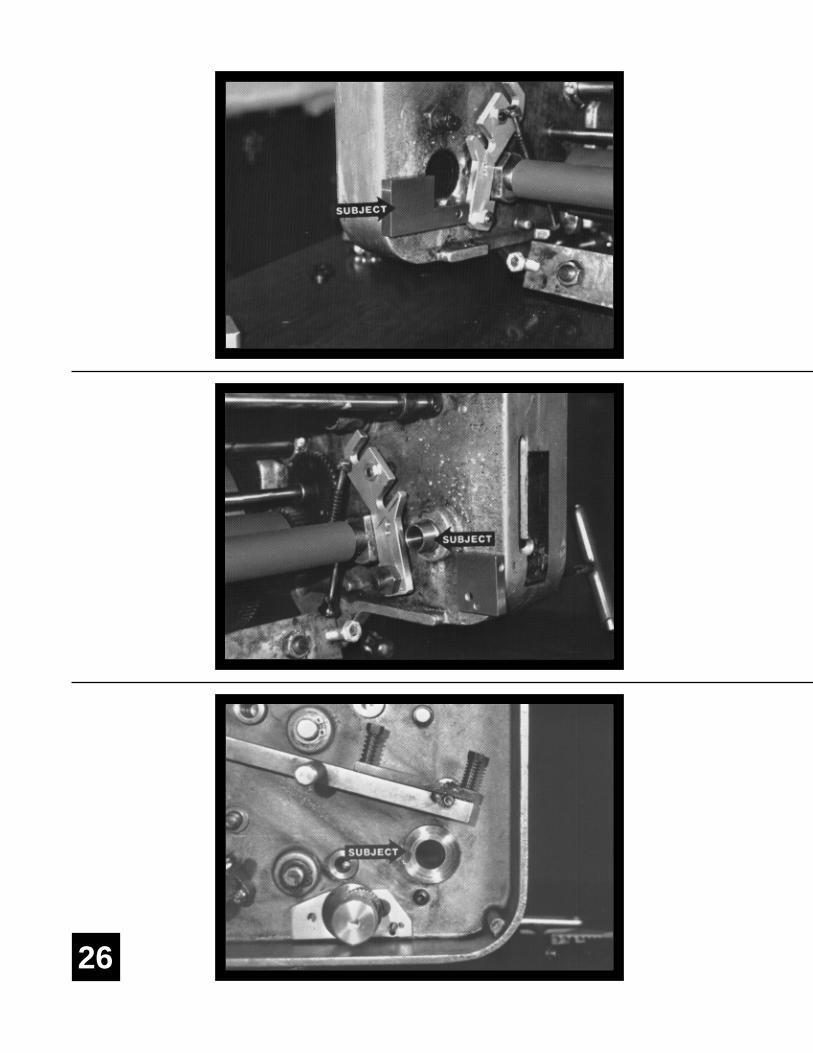
Install flanged water pan block spool (subject arrow) at NOPS.Flange will go to the outside of the T-Head frame and "flat"pointing toward radius in casting (subject arrow).
Install water pan block at NOPS (subject arrow). Block held inplace by bolt going through spool in previous step. Parallel theback of the block with the back of the T-Head frame and fullytighten bolt.
Install bolt and washer for OPS water pan block in frame(subject arrow).
26
27
13
14
15
INSTALLATION
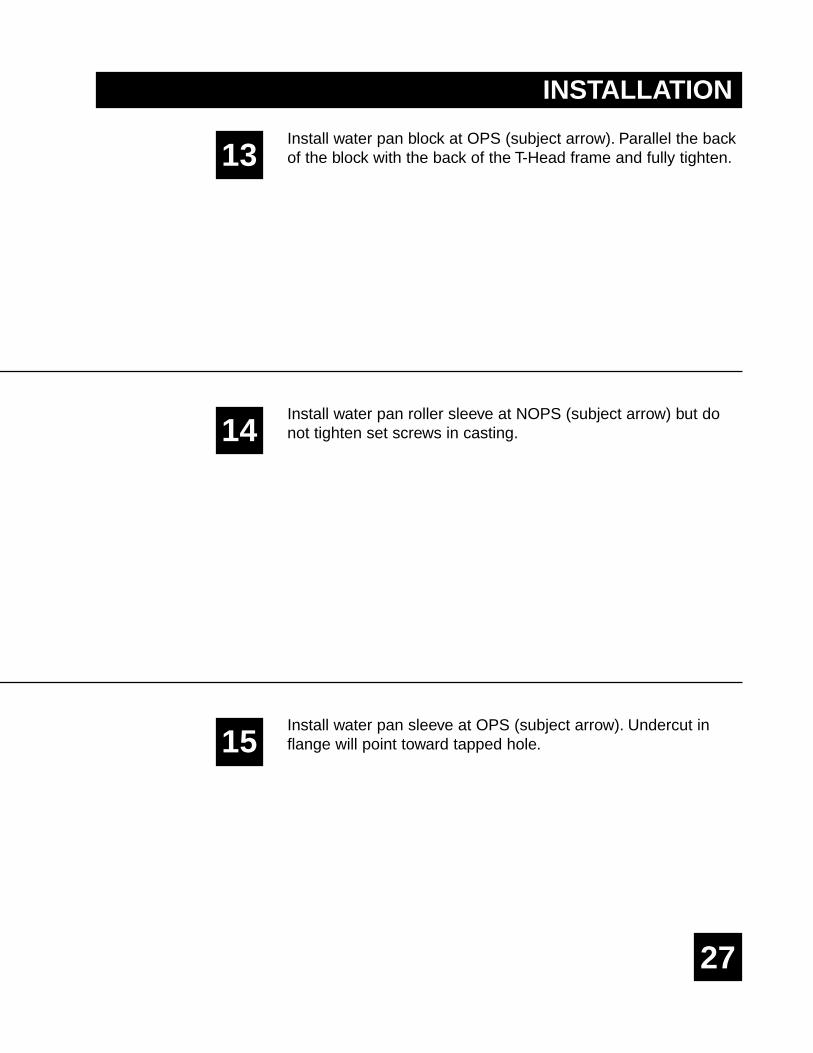
Install water pan block at OPS (subject arrow). Parallel the backof the block with the back of the T-Head frame and fully tighten.
Install water pan roller sleeve at NOPS (subject arrow) but donot tighten set screws in casting.
Install water pan sleeve at OPS (subject arrow). Undercut inflange will point toward tapped hole.
28
29
16
17
18
INSTALLATION
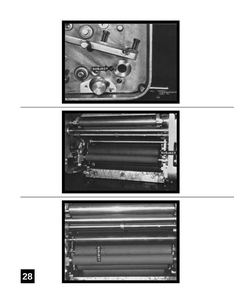
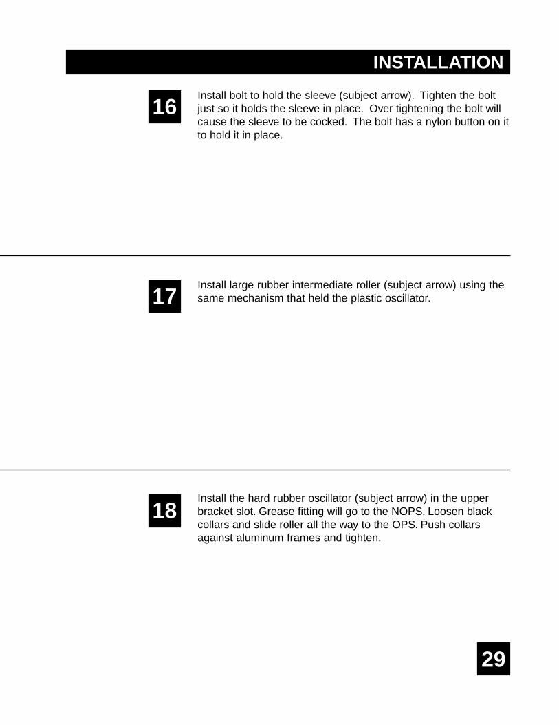
Install bolt to hold the sleeve (subject arrow). Tighten the boltjust so it holds the sleeve in place. Over tightening the bolt willcause the sleeve to be cocked. The bolt has a nylon button on itto hold it in place.
Install large rubber intermediate roller (subject arrow) using thesame mechanism that held the plastic oscillator.
Install the hard rubber oscillator (subject arrow) in the upperbracket slot. Grease fitting will go to the NOPS. Loosen blackcollars and slide roller all the way to the OPS. Push collarsagainst aluminum frames and tighten.
30
31
19
20
21
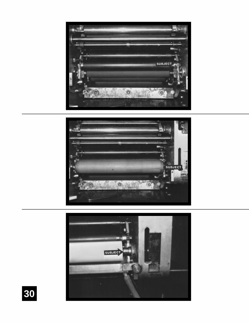
Install the metering roller in the lower bracket slot, with the pinto the NOPS and facing out (subject arrow). Center meteringroller relative to small transfer roller beneath it.
Install the pan roller. Insert eccentric shaft through OPS sleevethen through roller and into NOPS sleeve. Push shaft all the wayto NOPS until aluminum arm stops against flange on OPSsleeve.
Push NOPS sleeve (subject arrow) against the end of the panroller and check to see that pan roller is centered relative tometering roller. Lock the sleeve in place using the set screw inthe casting.
YOU ARE NOW READY TO MAKE FINAL ADJUSTMENTS.
INSTALLATION
32
33
1
2
3
FINAL ADJUSTMENTS
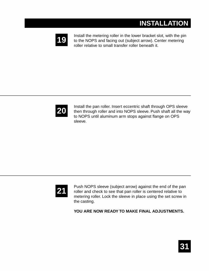
Loosen lock knob and rotate ratchet mechanism clockwise untilthe black eccentric stops against the pin, then retighten knob (lefthand subject arrow). Next, slowly rotate pan roll shaft (right handsubject arrow) counterclockwise while watching how the gapbetween the pan roller and metering roller closes. If one end of thepan roller contacts the metering roller before the other, then thepan roller must be paralleled to the metering roller. To do this,adjust the black eccentric (with yellow dot) on the hanger bracket.Turning the eccentric clockwise will lower the metering roller onthe NOPS, turning it counterclockwise will raise it. Alwaysremember to keep the hanger bracket pushed all the way againstthe transfer roller bearing housing when adjusting eccentric. Afterapproximate parallel has been obtained, tighten nut againsteccentric.
Turn the pan roller shaft counterclockwise until you can feelpressure being applied between pan and metering rollers. Whileholding the roller in this position, loosen aluminum arm on thepan roller shaft and push against the eccentric on the ratchetmechanism. Make sure the cutout on the arm fits behind theflange of the ratchet eccentric. In this position, retighten bolt toclamp arm to pan roller shaft.
Ink-up the T-51 system. Apply a small amount of ink directly tothe dampener oscillator. Idle the press for about 1 minute whilewatching roller operation in the dampening system. If everythingappears to be normal, proceed to setting the stripe from thewater form roller to the plate. This is done in the exact samemanner as prior to installing Crestline. The stripe shouldmeasure 5/32". Use the stripe gauge provided to check this.

34
4
5
6
Now proceed to set the pressure between the pan and meteringrollers in the dampener. After the press sits still for 20-30seconds, you will be able to bring up a stripe on the pan rollerby bumping the press forward with the hand wheel. First, makesure the stripe is straight. If not, this means further adjustmentof the hanger eccentric is necessary (refer to step 1). If thestripe is straight, check its measurement with the gauge. Itshould be 5/32". If not loosen the aluminum arm on the panroller shaft and turn it clockwise to decrease the stripe,counterclockwise to increase the stripe. After the proper stripehas been obtained, retighten arm against eccentric.
After roller pressures are set, check the water level in the pan. Itshould be approximately half way up in the pan. If you see aring of water on each end of the pan roller while the press isrunning, the water level is sufficiently high. Water level isadjusted by the thumb screw located on the filler assembly.
Always check to see that the ink form pressures as well as platecylinder to blanket cylinder pressure is set to Townsendspecifications. This is necessary for proper dampenerperformance.
Replace side covers. It will be necessary to notch OPS cover toclear new dampener knobs.
YOU ARE NOW READY TO PRINT
FINAL ADJUSTMENTS
35
START OF DAY
RUNNINGDURING THE DAY
BASIC OPERATION
36
A. Make sure all rollers are secure in their properposition.
B. Turn knurled knob on ratchet assembly clockwiseuntil it stops.
C. Before adding water, ink-up the dampener. This isdone either by applying a small amount of ink directlyto the dampener oscillator, or by dropping both waterand ink form rollers to the plate and allowing thedampener to ink-up from the plate.
D. Place water bottle in bracket. Accel recommend usingthe proper fountain solution formulated for the specificplate type being run on the press.
A. Typically, the Crestline Dampener should not have tobe adjusted from job to job. The form roller settingshould never be changed unless it has deviated fromthe factory specification of 5/32" to the plate.
B. If necessary, the amount of water fed to the plate canbe adjusted by turning the knurled ratchet knob. Youare running minimum water with the knob turned fullyclockwise. If you need more water, loosen the lock-knob, turn ratchet assembly counterclockwise one"click" at a time until proper moisture is achieved, thenretighten lock knob. Make sure the arm on the panroller shaft follows the black eccentric on the ratchetassembly. If necessary, turn the knurled knob on thepan roller shaft until the aluminum arm stops againstthe eccentric.
WASH UPSDURING THE DAY
CLEANING & MAINTENANCE
37
1. Remove bottle and drain the excess water from the pan.
2. Mount a cleanup mat to the press.
3. Turn on the press and squirt a small amount of presswash on the ink rollers and dampener oscillator. Avoidexcessive application of wash to the dampener or mostof it will end up in the water pan. Do not use an extremelyfast drying wash on the dampener as this can damagesoft rubber. Fast-dry washes should only be used onblankets!
4. Drop both the dampener and ink forms to the cleanupmat.
5. Remove water pan and clean any solution left in it.
6. Be sure to wipe excess clean up solution from the endsof the dampener metering and pan rollers.
1. Wash up dampener as describe above. Pay closeattention to cleaning the ends of the pan and meteringrollers that extend past the form rollers.
2. Spin the knurled knob counterclockwise and relievepressure between the metering and pan rollers.
3. Remove any excess wash that may remain on dampenermetering and pan rollers.
END OF THE DAY
38
CLEANING & MAINTENANCE
DEGLAZING THE DAMPENER
Periodic deglazing of water-soluble contaminants is necessarywith the Crestline®. Typically, once every 2 weeks is sufficient,unless you are running electrostatic plates on a daily basis,where deglazing should be performed weekly. Accelrecommends its product, Compound X, for deglazing purposes.Avoid deglazers containing pumice or gritty substances. Alwaysfollow deglazing with hot water and roller wash.
OILING AND GREASING THE DAMPENER
A. Place a small amount of grease on the gears once a month.
B. Inject grease into the oscillator grease fitting once a month.
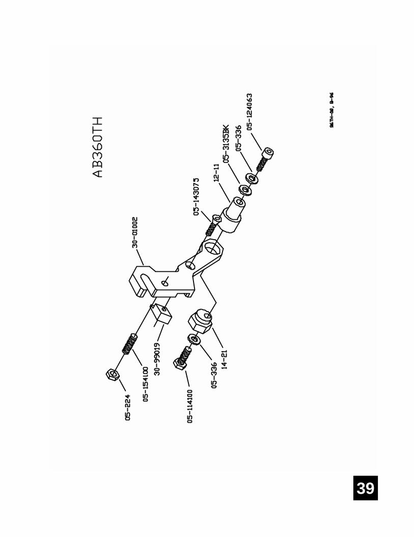
39
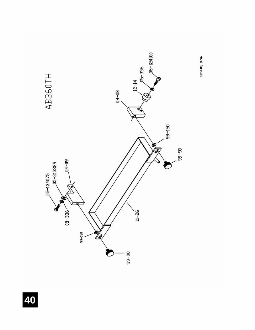
40
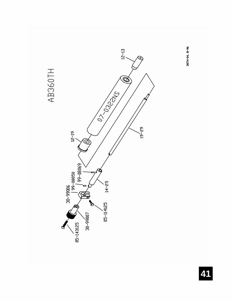
41
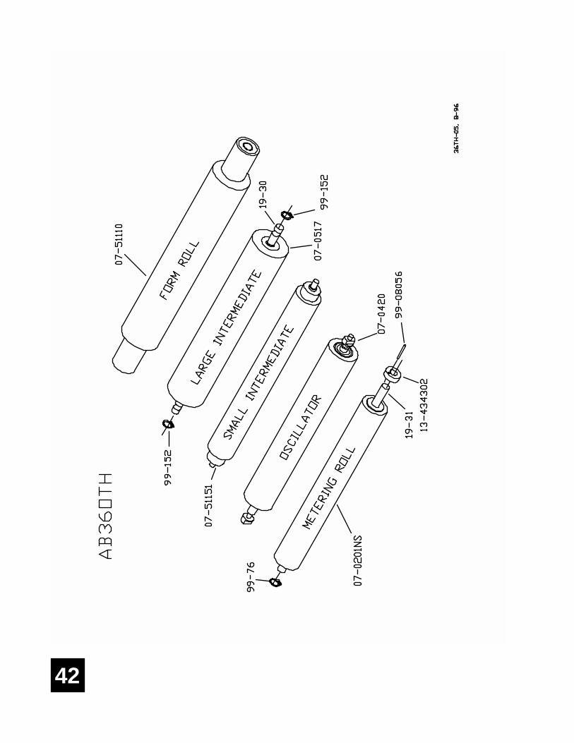
42


11103 Indian Trail, Dallas, TX 75229 Phone 972-484-6808, Fax 800-365-6510E-mail [email protected], Web Site www.accel-us.com