Embed Size (px)
Citation preview

Hamada RS34 & VS34
Satellite Unit
For Presses Originally Equipped With
Integrated Dampeners
X88-11301/2001
Rev-A
Crestline® Dampening System
Installation Instructions

GENERAL INFORMATION
ATTENTIONCRESTLINE®
DAMPENEROWNER!
SAFETYINFORMATION
FOR YOUR SAFETY, DO NOT DISENGAGE OR REMOVE ANYGUARDS FROM THE CRESTLINE® DAMPENER. THEDAMPENER CONTAINS SOME INWARD ROTATING ROLLERNIPS THAT CAN CAUSE INJURY IF LEFT UNGUARDED.
2
Accel Graphic Systems provides parts and service through itsauthorized distributors and dealers. Therefore, all requests forparts and service should be directed to your local dealer.
The philosophy of Accel Graphic Systems is to continually improveall of its products. Written notices of changes and improvementsare sent to Accel Graphic Systems' Dealers.
If the operating characteristics or the appearance of your productdiffers from those described in this manual, please contact yourlocal Accel Graphic Systems Dealer for updated information andassistance.
Always update your dampener when improvements are madeavailable, especially those related to safety.
YOUR AUTHORIZED CRESTLINE® DEALER IS:
THE SERIAL NUMBER OF YOURCRESTLINE® DAMPENER(S) IS:

GENERAL INFORMATION
BASICCONFIGURATION
OF CRESTLINE®
3
OPS = Operator's Side
NOPS = Non Operator's Side
TERMINOLOGY
TECHNICALASSISTANCE
For technical assistance during the installation, please contact:
ACCEL GRAPHIC SYSTEMS11103 Indian TrailDallas, TX 75229(972) 484-6808FAX (800) 365-6510E-MAIL [email protected] SITE www.accelgraphicsystems.com
Crestline® is covered by U.S. Patents and Patents Pending
Adjustmentsa. Form to Plateb. Upper Intermediate to
Lower Intermediatec. Metering to Pan
PlateCylinder
PB
FLI
UI M
a. 5/32 (4mm)
b. 5/32 (4mm)
c. 3/16 (5mm)
Roller DescriptionsF = FormB = Oscillator/BridgeLI = Lower IntermediateUI = Upper IntermediateP = PanM = Metering

GENERAL INFORMATION
REQUIRED TOOLS 1. Phillips Screwdriver
2. Standard Screwdriver
3. 8 mm Open End
4. 10 mm Open End
5. 13 mm Open End
6. 17 mm Open End
7. 2.5 mm Allen Wrench
8. 3 mm Allen Wrench
9. 4 mm Allen Wrench
10. 5 mm Allen Wrench
11. 2.5 mm Punch
12. 3.0 mm Punch
13. 5.0 mm Punch
14. Hammer
15. Snap Ring Pliers
4

PRE-INSTALLATION INFORMATION
5
1. Cut the ties holding the rollers and examine rollers for gouges,scratches, or nicks.
2. Check box and parts board to make sure all pieces are presentand nothing has broken in shipping.
3. Check the dampener for parallel. (Cutter bed works best.) Ifdampener rocks, it needs to be realigned. Loosen tie bar boltsat OPS and align the frames on the flat surface. Retighten bolts.

6
7
1
2
3
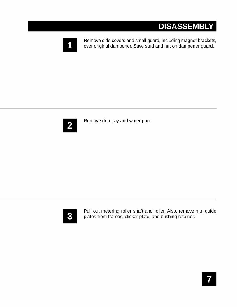
DISASSEMBLY
Remove side covers and small guard, including magnet brackets,over original dampener. Save stud and nut on dampener guard.
Remove drip tray and water pan.
Pull out metering roller shaft and roller. Also, remove m.r. guideplates from frames, clicker plate, and bushing retainer.
8

9
4
5
6
DISASSEMBLY
Remove lockout assembly at OPS.
Remove water adjustment knob, tension block, and then the rest ofthe adjustment assembly.
Remove extension springs, compression spring blocks, frame, andtransfer roller assembly. Knock out pins from all arms, disengagesnap rings, and pull out shaft through OPS.

10

11
7
8
9
DISASSEMBLY
Remove water linkage at OPS as indicated by arrows. It is helpfulto temporarily disconnect solenoid assembly to provide easieraccess.
Remove bronze bushings at OPS & NOPS on pan roller andremove roller. Next, loosen set screws near transfer roller andremove studs. The entire transfer roller assembly can then beremoved.
Temporarily remove the #1 ink form roller, and then remove wateroscillator and water oscillator brackets at OPS & NOPS.

12

13
DISASSEMBLY
Remove idler gear train at NOPS.10
11 Remove lower tie bar.

14

15
1
2
3
INSTALLATION
Install tie bar (lower subject arrow) into common holes in pressframes as shown. Note position of water pan mounting blocks.
Install mounting frames at OPS & NOPS using the provided spoolsand hardware as shown (see upper subject arrow in step 1).
Remove the NOPS shaft bushing. Insert the lift shaft assembly intothe press frame through the OPS. Retain the bushing at the OPSand NOPS with the screw provided. Push the lift shaft through theNOPS shaft bushing until it is flush with the outside. Push the setcollars up against the lift shaft bushing and tighten. The shaftshould rotate freely and be centered between press frames.

16

17
4
5
INSTALLATION
6
At OPS, slip control block over end of lift shaft and install armextension onto the slot in the original Hamada water form link usingthe provided bolts and washers.
Reinstall solenoid assembly which was temporarily disconnectedin disassembly step 7.
OPTIONAL SHORTCUTCheck dampener for square on cutter bed or flat surface. Apply ink toleft and right third of oscillator roller, leaving center third clean (seedrawing). Roll dampener by hand to smooth ink. You can adjust all theroller stripes on the table where it is easier to see, rather than when itis in the press. See Final Adjustments section for roller settinginstructions. After setting stripes, return to Installation step 7.
18

19
7
8
9
INSTALLATION
Make sure cable is attached as shown (subject arrow) and hangingloosely over the pivot studs.
NOTE: Be sure that the bridge roller is locked in the unbridgedposition.
Place single lever into the "Ink On" position and put dampener inthe press so the bearings (subject arrow, left hand picture) rest inthe mounting frame cradles (subject arrow, right hand picture).
Install bearing caps to hold dampener in place (subject arrow).
Do not adjust the center screw in the middle of the cap, it ispreset for the proper tension at the factory.

20

21
10
INSTALLATION
11
12
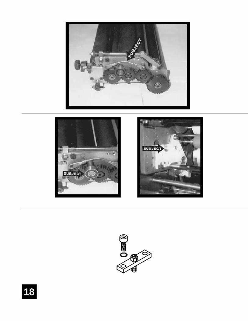
Install spring studs in satellite head frame (subject arrow).
Place cables over brass pulleys. Attach springs to cables & studs,making sure cable is in the groove of the brass pulleys.
Rotate head using manual knob to check gear mesh betweenthe form gear and plate cylinder gear.
Install the tie bar.

22
3
23
13
14
INSTALLATION
15
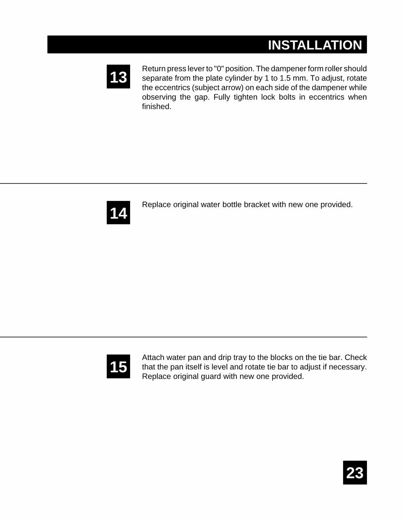
Return press lever to "0" position. The dampener form roller shouldseparate from the plate cylinder by 1 to 1.5 mm. To adjust, rotatethe eccentrics (subject arrow) on each side of the dampener whileobserving the gap. Fully tighten lock bolts in eccentrics whenfinished.
Replace original water bottle bracket with new one provided.
Attach water pan and drip tray to the blocks on the tie bar. Checkthat the pan itself is level and rotate tie bar to adjust if necessary.Replace original guard with new one provided.

24

25
1
2
3
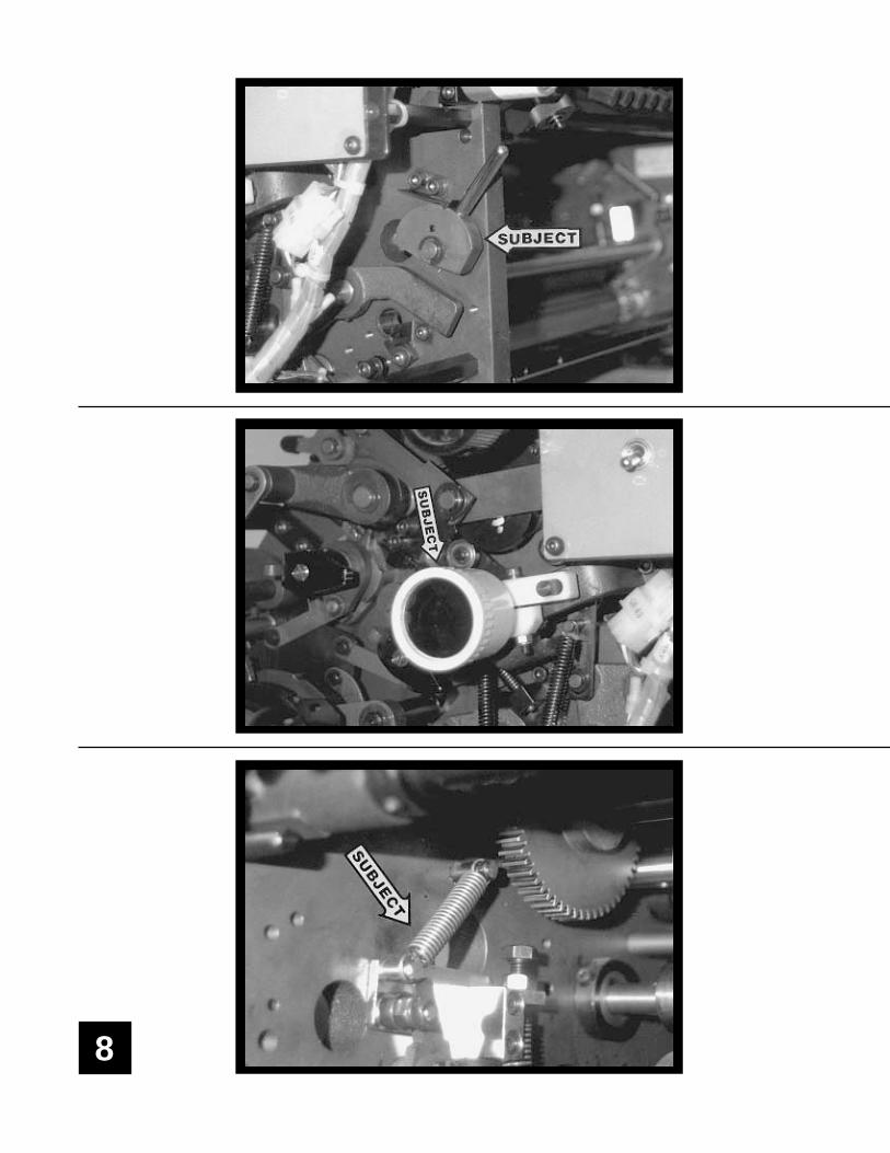
FINAL ADJUSTMENTS
Place press lever in the number 1 (water on) position. Rotatedampener lift shaft so that the flats of the cams are just touching thebearings on the dampener. In this position, tighten control block tolift shaft.
NOTE: If the lift cams are not centered to the dampenerbearings, then it may be necessary to recenter the shaft.
Dab ink on the dampener on a hard roller and turn the press by handat first to distribute the ink. Slowly jog and run the press until the inkis distributed evenly on all the dampener rollers.
Water Form to Plate
Drop the water form roller to the plate and check the stripe. It shouldbe 5/32" (4mm). Adjust the stripe using the stop screws on thedampener frame (subject arrow). Turning the screw in de-creases the stripe. Lock in place using lock nut.
Upper Intermediate to Lower Intermediate
Check the stripe between the upper intermediate &lower interme-diate rollers by dropping the water form to the plate and rotating thepress backwards (Clutches prevent dampener from turning back-wards with the water form off the plate. Dropping the form to theplate allows the ink to drive the unit backwards.)
Stripe should be 5/32" (4mm). Adjust by turning the screw on topof the hanger (subject arrow). Turning the screw down increasesthe stripe. Tighten lock nut when finished.
PlateCylinder
PB
FLI
UI M
5/32 (4mm)
PlateCylinder
PB
FLI
UI M
5/32 (4mm)

26

27
4
5
6
FINAL ADJUSTMENTS
Upper Intermediate to Pan
This pressure is set automatically when setting the intermediate toform in step 3.
Metering to Pan
Jog the press forward and observe the stripe on the pan roller. Itshould be 3/16" (4.5mm - 5mm). Turn the knurled meteringknobs (left subject arrow) clockwise to increase the stripe.
When the proper stripe has been obtained, spin the ratchet gears(right hand subject arrow) down until they bottom out on the studand secure the ratchet gear to the knurled knobs with the setscrews.
Bridge to Water Form
Pressure between the bridge roller and water form is spring loadedand preset at factory.
Water Pan Level
Adjust water level in pan by raising or lowering the original waterbottle mechanism.
PlateCylinder
PB
FLI
UI M
3/16" (5mm)

A. Make sure all the rollers are in place.
B. Spin knurled knobs until the ratchet stops.
C. Mount plate to cylinder. Wipe down all plates before running.Pre-ink the Crestline® dampener before running the plates withan extremely light coverage of ink by engaging the bridge roller.Bridge roller engages by pulling back and up on the bridge rollerbracket to allow the roller to move toward the inker. To disengage,pull back and then down until the bracket notch rest on theshoulder bolt.
D. Place water bottle in bracket.
NOTE: Accel recommends using the proper fountain solutionfor the plate material being run on the press. A good acid/gumetch should be used with metal plates.
A. In general, the Crestline® should not have to be adjusted fromjob to job. The form roller setting should never be changedunless it has deviated from the factory specification of 5/32" tothe plate.
B. Adjustments to the amount of water fed to the plate are madeby the knurled knobs that apply pressure to the metering roller.The dampener has been set up for minimum water. To increasethe water to the plate, turn the knurled knobs counter clockwise1 or 2 clicks at a time. This opens the gap between the meteringand pan rollers and allows more water to the plate.
C. In general, more water will only be required when going from ametal plate to an electrostatic or Silvermaster type plate.
START OF DAY
RUNNINGDURING THE DAY
BASIC OPERATION
28

WASH UPSDURING THE DAY
1. Remove bottle and drain the excess water from the pan.
2. Mount a metal plate to the press.
3. Turn on the press and squirt a small amount of press wash onthe ink rollers.
4. Engage the bridge roller by rotating the levers at the OPS &NOPS towards the feed end of the press, dropping the bridgeonto the ink form roller.
5. Use wash up attachment as normal. When the press is cleandisengage bridge roller by pulling back on the levers untilbearing on bridge roller drops into detent.
6. Remove water pan and clean any solution left in it.
7. Be sure to wipe excess clean up solution from the ends of thedampener metering and pan rollers.
1. Wash up press. Pay close attention to cleaning the ends of thepan and metering rollers that extend past the form rollers.
2. Spin the knurled knobs up until the metering roller can beremoved.
3. Remove metering roller and wipe down thoroughly to removeany excess wash that may be on the roller.
END OF THE DAY
CLEANING & MAINTENANCE
29

DEGLAZINGTHE DAMPENER
Periodic deglazing of water-soluble contaminants will be necessarywith the Crestline®. Typically, once every 2-3 weeks will be sufficient,unless you are running electrostatic plates on a daily basis whereasdeglazing should be performed weekly. A 50/50 solution ofhousehold ammonia and hot water can be used for deglazingpurposes. If you prefer a commercially available deglazer, avoidthose containing pumice or gritty substances. Always followdeglazing with straight water and then roller wash. Accel offers aproduct called COMPOUND X that we recommend for deglazingour system. Contact your dealer or Accel for more information.
A. Place a small amount of grease on the gears once a month.
B. Inject grease into the oscillator grease fitting once a month.
OILING ANDGREASING THE
DAMPENER
CLEANING & MAINTENANCE
30

CRESTLINE®
CLEANING & MAINTENANCE CHART
31
CLEANING & MAINTENANCE
Wash Rollers
Deglaze Rollers
Metal Plate Users
Silvermaster Plate Users
Electrostatic Plate Users
Grease Gears
Inspect Ball Bearings
Check Roller Pressures
Check Roller Surfaces
Daily Weekly Bi-Weekly Monthly

32

33
34

35
36

37

38

39

40

41

42

43

44


11103 Indian Trail, Dallas, TX 75229 Phone 972-484-6808, Fax 800-365-6510E-mail [email protected], Web Site www.accel-us.com


![IP Event Dampening - Cisco...dampening [half-life-period reuse-threshold] Enablesinterfacedampening. [suppress-threshold max-suppress [restart-penalty]] Step4 •Enteringthedampening](https://img.pdfslide.us/doc/110x75/612e12771ecc515869429546/ip-event-dampening-cisco-dampening-half-life-period-reuse-threshold-enablesinterfacedampening.jpg)