Embed Size (px)
Citation preview

Owner's Manual _'_ dr
CRAFTSMAN°20.0 HPELECTRIC START50" MOWER6 SPEED
LIBRARY;
ReceivedcopiedEntered
LiSRcceived (NR!_9_Sf --
Scan,_cd
GARDEN TRACTOR
Model No917.273050
• Safety• Assembly• Operation• Maintenance
• Repair Parts
CAUTION:
Read and follow all SafetyRules and Instructions beforeoperating this equipment.
For answers to your questionsabout this product, Call:1-800-659-5917Sears Craftsman Help Une5 am- 5 pm, Mon- Sat
SEARS, ROEBUCK AND CO., HOFFMAN ESTATES, IL 60179Visit our Craftsman website:www.sears.com/craftsman

Warranty ...............................................2
Safety Rules ................................. ......... 2Product Specifications .......................... 5Assembly ............................................... 8Operation ............................................ 12Maintenance Schedule ...................... 18
Maintenance ....................................... 18Service and Adjustments .................... 22Storage ............................................... 29Troubleshooting ................................. 30Repair Parts ........................................ 34Parts Ordering ..................... Back Cover
LIMITED TWO YEAR WARRANTY ON CRAFTSMAN RIDING EQUIPMENT
For two (2) years from the date of purchase, if this Craftsman Riding Equipment ismaintained, lubricated and tuned up according to the instructions in the owner'smanual, Sears will repair or replace, free of charge, any parts found to be defective inmaterial or workmanship.This Warranty does not cover:• Expendable items which become worn during normal use, such as blades, spark
plugs, air cleaners, belts, etc.• Tire replacement or repair caused by punctures from outside objects, such as nails,
thorns, stumps, or glass.• Repairs necessary because of operator abuse, negligence, improper storage or
accident or the failure to maintain the equipment according to the instructionscontained in the owner's manual.
• Riding equipment used for commercial or rental purposes.LIMITED 90 DAY WARRANTY ON BAI-IERY
For ninety (90) days from date of purchase, if any battery included with this ridingequipment proves defective in material or workmanship and our testing determines thebattery wil! not hold a charge, Sears will replace the battery at no charge. In-homewarranty service on your Craftsman riding equipment is available at no charge for 30days from the date of purchase. Please contact your nearest service center. After 30days from the date of purchase, warranty service is available by taking your Craftsmanriding equipment to your nearest Sears Service Center. (In-home warranty service willstill be available after 30 days from the date of purchase but a standard trip charge willapply). This warranty applies only while this product is in the United States. ThisWarranty gives you specific legal rights, and you may also have other rights which mayvary from state to state.Sears, Roebuck and Co., D/817 WA, Hoffman Estates, IL 60179
IMPORTANT: This cutting machine iscapable of amputating hands and feetand throwing objects. Failure to observethe following safety instructions couldresult in serious injury or death.GENERAL OPERATION
• Read, understand, and follow allinstructions in the manual and on the
machine before starting.• Only allow responsible adults, who are
familiar with the instructions, tooperate the machine.
• Clear the area of objects such asrocks, toys, wire, etc., which could bepicked up and thrown by the blade. 2
• Be sure the area is clear of other
people before mowing. Stop machineif anyone enters the area.
• Never carry passengers.• Do not mow in reverse unless abso-
lutely necessary. Always look downand behind before and while backing.
• Be aware of the mower dischargedirection and do not point it at anyone.Do not operate the mower withouteither the entire grass catcher or theguard in place.Slow down before turning.

• Never leave a running machineunattended. Always turn off blades, setparking brake, stop engine, andremove keys before dismounting.
• Turn off blades when not mowing.• Stop engine before removing grass
catcher or unclogging chute.• Mow only in daylight or good artificial
light.• Do not operate the machine while
under the influence of alcohol ordrugs.
• Watch for traffic when operating nearor crossing ro_idways.
• Use extra care when loading orunloading the machine into a trailer ortruck.
• Data indicates that operators, age 60years and above, are involved in alarge percentage of riding mower-related injuries. These operatorsshould evaluate their ability to operatethe riding mower safely enough toprotect themselves and others fromserious injury.
SLOPE OPERATION
Slopes are a major factor related to loss-of-control and tipover accidents, whichcan result in severe injury or death. Allslopes require extra caution. If youcannot back up the slope or if you feeluneasy on it, do not mow it.DO:
• Mow up and down slopes, not across.• Remove obstacles such as rocks, tree
limbs, etc.• Watch for holes, ruts, or bumps.
Uneven terrain could overturn the
machine. Tall grass can hide ob-stacles.
• Use slow speed. Choose a low gearso that you will not have to stop or shiftwhile on the slope.
• Follow the manufacturer's recommen-
dations for wheel weights or counter-weights to improve stability.
• Use extra care with grass catchers orother attachments. These can changethe stability of the machine.
• Keep all movement on the slopes slowand gradual. Do not make suddenchanges in speed or direction.
• Avoid starting or stopping on a slope. If
tires lose traction, disengage theblades and proceed slowly straightdown the slope.
DO NOT:
• Do notturn on slopes unless neces-sary, and then, turn slowly andgradually downhill, if possible.
• Do not mow near drop-offs, ditches, orembankments. The mower couldsuddenly turn over if a wheel is overthe edge of a cliff or ditch, or if an edgecaves in.
• Do not mow on wet grass. Reducedtraction could cause sliding.
• Do nottry to stabilize the machine byputting your foot on the ground.
• Do not use grass catcher on steepslopes.
CHILDREN
Tragic accidents can occur if the operatoris not alert to the presence of children.Children are often attracted to the
machine and the mowing activity. Neverassume that children will remain whereyou last saw them.• Keep children out of the mowing area
and under the watchful care of anotherresponsible adult.
• Be alert and turn machine off ifchildren enter the area.
• Before and when backing, look behindand down for small children.
• Never carry children. They may fall offand be seriously injured or interferewith safe machine operation.
• Never allow children to operate themachine.
• Use extra care when approachingblind corners, shrubs, trees, or otherobjects that may obscure vision.
SERVICE
• Use extra care in handling gasolineand other fuels. They are flammableand vapors are explosive.
Use only an approved container.Never remove gas cap or add fuelwith the engine running. Allowengine to cool before refueling. Donot smoke.Never refuel the machine indoors.Never store the machine or fuelcontainer inside where there is an
open flame, such as a water heater.
3

• Never run a machine inside a closedarea.
• Keep nuts and bolts, especially bladeattachment bolts, tight and keepequipment in good condition.
• Never tamper with safety devices.Check their proper operation regularly.
• Keep machine free of grass, leaves, orother debris build-up. Clean oil or fuelspillage. Allow machine to cool beforestoring.
Stop and inspect the equipment if youstrike an object. Repair, if necessary,before restarting.Never make adjustments or repairswith the engine running.Grass catcher components are subjectto wear, damage, and deterioration,which could expose moving parts orallow objects to be thrown. Frequentlycheck components and replace withmanufacturer's recommended parts,when necessary.
• Mower blades are sharp and can cut.Wrap the blade(s) or wear gloves, anduse extra caution when servicingthem.
• Check brake operation frequently.Adjust and service as required.
• Be sure the area is clear of other
people before mowing. Stop machineif anyone enters the area.
• Never carry passengers.• Do not mow in reverse unless abso-
lutely necessary. Always look downand behind before and while backing.
• Never carry children. They may fall offand be seriously injured or interferewith safe machine operation.
• Keep children out of the mowing areaand under the watchful care of another
responsible adult.• Be alert and turn machine off if
children enter the area.
Before and when backing, look behindand down for small children.
Mow up and down slopes (15 ° Max),not across.Remove obstacles such as rocks, treelimbs, etc.Watch for holes, ruts, or bumps.Uneven terrain could overturn the
machine. Tall grass can hide obsta-cles.
Use slow speed. Choose a low gearso that you will not have to stop or shiftwhile on the slope.Avoid starting or stopping on a slope. Iftires lose traction, disengage theblades and proceed slowly straightdown the slope.Do not turn on slopes unless neces-sary, and then, turn slowly and gradu-ally downhill, if possible.
Look for this symbol to point outimportant safety precautions. It meansCAUTION!!! BECOMEAWARE!!! YOURSAFETY IS INVOLVED.
_CAUTION: In order to preventaccidental starting when setting up,transporting, adjusting or making repairsalways disconnect spark plug wire andplace wire where it cannot contact sparkplug.
• LWARNING: The engine exhaust fromthis product contains chemicals known tothe State of California to cause cancer,birth defects, or other reproductive harm.
4

PRODUCT SPECIFICATIONS
GASOLINE 3.5 GALLONSCAPACITY UNLEADEDAND TYPE: REGULAR
)ILTYPE SAE 10W30
&PI-SF/SG/SH): (ABOVE 32°F)SAE 5W-30
(BELOW 32°F)
)ILCAPACITY: W/FILTER: 4.2PINTS
W/O FILTER: 3.7PINTS
_PARK PLUG: CHAMPION
GAP: .030") RC12YC
GROUND SPEED LO: HI:MPH): 0.7 1.7
1.4 3.32.3 5.4
REVERSE: 0.9 2.1
TIRE FRONT: 14 PSIPRESSURE: REAR: 10 PSI
CHARGING 15AMPS @ 3600RPMSY ST EM:
3AI-I-E RY: AMP/HR: 35MIN. CCA: 280CASE SIZE:U 1R
3LADE BOLT 27-35 FT. LBSTORQUE:
CONGRATULATIONS on your purchaseof a Craftsman Tractor. It has been
designed, engineered and manufacturedto give you the best possible depend-ability and performance.Should you experience any problem youcannot easily remedy, please contactyour nearest Sears Authorized ServiceCenter. We have competent, well-trainedtechnicians and the proper tools toservice or repair this tractor.Please read and retain this manual. Theinstructions will enable you to assembleand maintain your tractor properly.Always observe the "SAFETY RULES".
MAINTENANCE AGREEMENT
A Sears Maintenance Agreement isavailable on this product. Contact yournearest Sears store for details.CUSTOMER RESPONSIBILITIES
• Read and observe the safety rules.• Follow a regular schedule in maintain-
ing, caring for and using your tractor.• Follow the instructions under "Mainte-
nance" and "Storage" sections of thisowner's manual.
_WARNING: This tractor is equippedwith an internal combustion engine andshould not be used on or near anyunimproved forest-covered, brush-covered or grass-covered land unlessthe engine's exhaust system is equippedwith a spark arrester meeting applicablelocal or state laws (if any). If a sparkarrester is used, it should be maintainedin effective working order by the opera-tor.In the state of California the above isrequired by law (Section 4442 of theCalifornia Public Resources Code).Other states may have similar laws.Federal laws apply on federal lands. Aspark arrester for the muffler is availablethrough your nearest Sears AuthorizedService Center/Department (SeeREPAIR PARTS section of this manual).

Parts Bag contents shown full size
(1) Shoulder Bolt 5/16-18
(1) Knob
17/32 x 1-3/16 x 12 Gauge
(3) Retainer Springs (double loop)
(4) Retainer Springs (single loop)

Parts packed separately in carton Parts Bag contents not shown full size
Seat
VideoCassette
(2) Washers(2) Shoulder 3/8 x 7/8 x 14 Gauge _)
Bolts (2) Center-
_ lock NutsSteering(2) Gauge t v / WheelWheels __ J Insert
SteeringWheel
(2) Front Link Assemblies
I II II
II
II I
Manual Parts Bag
(2) Keys
Slope Sheet
Steering Sleeve
Steering SleeveExtension
7

Your new tractor has been assembled at the factory with exception of those parts leftunassembled for shipping purposes. To ensure safe and proper operation of yourtractor all parts and hardware you assemble must be tightened securely. Use thecorrect tools as necessary to insure proper tightness. Review the video cassette beforeyou begin.TOOLS REQUIRED FOR ASSEMBLY
A socket wrench set will make assemblyeasier. Standard wrench sizes you needare listed below.
(1) 9/16"wrench (1) Pliers(1) 1/2" wrench (1) Utility knife(1) 3/4" socket with
drive ratchet
(1) Tire pressure gauge
When right or left hand is mentioned inthis manual, it means, from your point ofview, when you are in the operatingposition (seated behind the steeringwheel).
TO REMOVE TRACTOR FROMCARTONUNPACK CARTON
• Remove all accessible loose parts andparts boxes from shipping carton.
• Cut, from top to bottom, along lines onall four corners of shipping carton, andlay panels flat.
• Remove mower and packing materi-als.
• Check for any additional loose parts orboxes and remove.
_ ,..F"'_:_ Stee ring
_..-J" Wheel Insert
_- Hex Bolto_ Lock Washer
Steering _ Large Flat
Wheel_t(eep_i:_el
Steering _ .Sleeve __::_'-TabsExtension I
Steering Shaft _ .-_\.
SteerinSleeve
• Snap steering wheel insert into centerof steering wheel.
• Remove protective materials fromtractor hood and grill.
IMPORTANT: Check for and remove anystaples in skid that may puncture tireswhere tractor is to roll off skid.
BEFORE ROLUNG TRACTOR OFFSKIDAI'I'ACH STEERING WHEEL
• Remove hex bolt, lock washer andlarge flat washer from steering shaft.
• Position front wheels of the tractor sothey are pointing straight forward.
• Slide the steering sleeve over thesteering shaft.
• Align tabs and press steering sleeveextension into bottom of steeringwheel.
• Position steering wheel so cross barsare horizontal (left to right) and slideonto steering wheel adapter.
• Secure steering wheel to steeringshaft with hex bolt, lock washer andlarge flat washer previously removed.Tighten securely.
8
HOW TO SET UP YOUR TRACTORCHECK BA'n'ERY
Lift hood to raised position.If this battery is put into service aftermonth and year indicated on label(label located between terminals)charge battery for minimum of onehour at 6-10 amps. (See "BATTERY"in Maintenance section of this manual
for charging instructions).
"" "' ' Label
'I
.<.
-..%

INSTALL SEAT
Adjust seat before tightening adjustmentknob.
• Remove cardboard packing on seatpan.
• Place seat on seat pan and assembleshoulder bolt. Tighten shoulder boltsecurely.
• Assemble adjustment knob and flatwasher loosely. Do not tighten.
• Lower seat into operating positionand sit on seat.
• Slide seat until a comfortable positionis reached which allows you to pressclutch/brake pedal all the way down.
• Get off seat without moving itsadjusted position.
• Raise seat and tighten adjustmentknob securely.
Seat
Shoulder Seat PanBolt
AdjustmentKnob
Flat Washer
TO ROLLTRACTOR OFF SKID (SeeOperation section for location andfunction of controls)
,, Press lift lever plunger and raiseattachment lift lever to its highestposition.
• Release parking brake by depressingclutch/brake pedal.
• Place gearshift lever in neutral (N)position.
• Roll tractor forward off skid.TO DRIVE TRACTOR OFF SKID
WARNING: Before starting, read,understand and follow all instructions in
the Operation section of this manual. Besure tractor is in a well-ventilated area.Be sure the area in front of tractor is
clear of other people and objects.• Be sure all the above assembly steps
have been completed.• Check engine oil level and fill fuel
tank with gasoline.
• Sit on seat in operating position,depress clutch/brake pedal and set theparking brake.
• Place gear shift lever in neutral (N)position.
• Press lift lever plunger and raiseattachment lift lever to its highestposition.
• Start the engine. After engine hasstarted, move throttle control to idleposition.
• Depress clutch/brake pedal into full"BRAKE" position and hold. Movegearshift lever to 1st gear.
• Slowly release clutch/brake pedal andslowly drive tractor off skid.
• Apply brake to stop tractor, set parkingbrake and place gearshift lever inneutral position.
• Turn ignition key to "OFF" position.Continue with the instructions that follow.
CHECK TIRE PRESSURE
The tires on your tractor were overin-flated at the factory for shipping pur-poses. Correct tire pressure is importantfor best cutting performance.• Reduce tire pressure to PSI shown in
"PRODUCT SPECIFICATIONS"section of this manual.
CHECK BRAKE SYSTEM
After you learn how to operate yourtractor, check to see that the brake isproperly adjusted. See "TO ADJUSTBRAKE" in the Service and Adjustmentssection of this manual.
9

INSTALL MOWER AND DRIVE BELT
Be sure tractor is on level surface andmower suspension arms are raised withattachment lift control (see Know YourTractor in the Operation section). Engageparking brake.• Cut and remove ties securing anti-
sway bar and be_ts. Swing anti-swaybar to left side of mower deck.
• Slide mower under tractor with
discharge guard to right side of tractor.IMPORTANT: Check belt for properrouting in all mower pulley grooves.Install belt into electric clutch pulleygroove.• Install one front link in top hole of the
left hand front mower bracket and lefthand front suspension bracket. Retainwith two single loop retainer springsas shown.
• Install second front link in right handfront suspension bracket only andretain with single loop retainer springas shown.
• Slide right side of mower back andinstall link in top hole of right handfront mower bracket. Retain with
single loop retainer spring as shown.• Turn height adjustment knob counter-
clockwise until it stops.• Lower mower linkage with attachment
lift control.
• Place the suspension arms on inward
pointing deck pins. If necessary, rockand raise front of mower to align deckpins with the holes in suspensionarms. Retain with double loop retainersprings with loops down as shown.
• Connect anti-sway bar to chassisbracket under left footrest and retain
with double loop retainer spring.• Turn height adjustment knob clock-
wise to remove slack from mower
suspension.• Raise deck to highest position.• Assemble gauge wheels as shown
using long shoulder bolts, 3/8 wash-ers, and 3/8-1 6 center Iocknuts.Tighten securely.
• Adjust gauge wheels before operatingmower as shown in the Operationsection of this manual.
CHECK MOWER LEVELNESS
For best cutting results, mower should beproperly leveled. See 'q-O LEVELMOWER PIOUSING" in the Service and
Adjustments section of this manual.CHECK FOR PROPER POSITION OFALL BELTS
See the figures that are shown forreplacing motion, mower drive, andmower blade drive belts in the Service
and Adjustments section of this manual.Verify that the belts are routed correctly.
Double LoopRetainer 5
Left HandGaugeWheel Bar
Double LoopRetainer Spring (Inward
pins)
FrontFror_ SuspensionLinks
SuspensionArm_
Shoulder3olt
Use Pliers ForRetainer Springs
3/8-16CenterLocknut
Anti-SwayBar
IdlerPulley
Single LoopRetainerSprings
FrontMowerBracket
Discharge
10

v" CHECKLIST
Before you operate and enjoy your newtractor, we wish to assure that you receivethe best performance and satisfactionfrom this quality product.Please review the following checklist:,/ All assembly instructions have been
completed./ No remaining loose parts in carton.,/Battery is properly prepared and
charged. (Minimum 1 hour at 6 amps).,I Seat is adjusted comfortably and
tightened securely.,/All tires are properly inflated. (For
shipping purposes, the tires wereoverinflated at the factory).
,/Be sure mower deck is properly leveledside-to-side/front-to-rear for best cuttingresults. (Tires must be properly inflatedfor leveling).
•/ Check mower and drive belts. Be sure
they are routed properly around pulleysand inside all belt keepers.
,/Check wiring. See that all connectionsare still secure and wires are properlyclamped.
While learning how to use your tractor,pay extra attention to the followingimportant items:,/ Engine oil is at proper level.,/" Fuel tank is filled with fresh, clean,
regular unleaded gasoline.,/" Become familiar with all controls - their
location and function. Operate thembefore you start the engine.
,/Be sure brake system is in safe operat-ing condition.
11

These symbols may appear on your tractor or in literature supplied with the product.Learn and understand their meaning.
BAI-FERY CAUTION OR REVERSE FORWARD FAST SLOWWARNING
_I_ENG'NEONI_!_IENG'NEOFFO"PRESSURE_L'G"TSON_OV_,_Mp_
FUEL CHOKE MOWER HEIGHT PARKING BRAKE UNLOCKED MOWER LIFTLOCKED
R N H LATTACHMENT REVERSE NEUTRAL HIGH LOW
CLUTCH ENGAGED PARKING BRAKE
ATTACHMENT KEEP AREA CLEAR SLOPE HAZARDS
IGNITION CLUTCH DISENGAGED
i:i::iiJ::i:i_iii_....................._iii:.:.::iiiiii_iiii
(SEE SAFETY RULES SECTION)
DANGER, KEEP HANDS AND FEET AWAY FREE WHEEL
(Automatic Models only)
12

KNOW YOUR TRACTOR
READ THIS OWNER'S MANUAL AND SAFETY RULES BEFORE OPERATINGYOUR TRACTOR
Compare the illustrations with your tractor to familiarize yourself with the locations ofvarious controls and adjustments. Save this manual for future reference.
Ammeter
IgnitionSwitch Position
Throttle Control
Clutch/Brake
Clutch Switch
Lift LeverPlunger
AttachmentLift Lever
ChokeControl Brake
Height _ Shift LeverAdjustmentKnob
Gear Shift Lever \
\Our tractors conform to the safety standards of the American National Standards
Institute.
ATTACHMENT CLUTCH SWITCH: Usedto engage the mower blades, or otherattachments mounted to your tractor.LIGHT SWITCH: Turns the headlights onand off.THROTTLE CONTROL: Used to controlengine speed.CLUTCH/BRAKE PEDAL: Used for
declutching and braking the tractor andstarting the engine.CHOKE CONTROL: Used when startinga cold engine.HEIGHT ADJUSTMENT KNOB: Used to
adjust the mower cutting height.GEARSHIFT LEVER: Selects the speedand direction of the tractor.
RANGESHIFT LEVER: Allows high (H)and low (L) speed for all forward andreverse gears.ATTACHMENT LIFT LEVER: Used toraise and lower the mower deck or other
attachments mounted to your tractor.LIFT LEVER PLUNGER: Used to release
attachment lift lever when changing itsposition.IGNITION SWITCH: Used for starting andstopping the engine.AMMETER: Indicates battery charging(+) or discharging (-)_PARKING BRAKE: Locks clutch/brake
into the brake position.
13

The operation of any tractor can result in foreign objects thrown into theeyes, which can result in severe eye damage. Always wear safetyglasses or eye shields while operating your tractor or performing anyadjustments or repairs. We recommend a wide vision safety mask overspectacles or standard safety glasses.
HOW TO USE YOUR TRACTOR
TO SET PARKING BRAKE
Your tractor is equipped with an operatorpresence sensing switch. When engineis running, any attempt by the operatorto leave the seat without first setting theparking brake will shut off the engine.• Depress clutch/brake pedal into full
"BRAKE" position and hold.• Place parking brake lever in "EN-
GAGED" position and releasepressure from clutch/brake pedal.Pedal should remain in "BRAKE"
position. Make sure parking brake willhold tractor secure.
Push-In to Attachment ClutchChoke "Disengaged" Switch Pull Out To
Position
Pedal "Drive" "Disengaged"Position PositionSTOPPING
Gear-Sh_Lever
MOWER BLADES -
• To stop mower blades, move attach-ment clutch switch to "DISENGAGED"
position.
GROUND DRIVE -
• To stop ground drive, depress clutch/brake pedal into full "BRAKE" position.
• Move gearshift lever to neutral (N)position.
ENGINE -
• Move throttle control to slow position.NOTE: Failure to move throttle control to
slow position and allowing engine toidle before stopping may cause engineto "backfire".
• Turn ignition key to "OFF" position andremove key. Always remove keywhen leaving tractor to prevent
unauthorized use.
• Never use choke to stop engine.IMPORTANT: Leaving the ignition switchin any position other than "OFF" willcause the battery to be discharged,(dead).NOTE: Under certain conditions when
tractor is standing idle with the enginerunning, hot engine exhaust gases maycause "browning" of grass. To eliminatethis possibility, always stop engine whenstopping tractor on grass areas.
_CAUTION: Always stop tractorcompletely, as described above, beforeleaving the operator's position; to emptygrass catcher, etc.THROTTLE CONTROL
Always operate engine at full throttle.• Operating engine at less than full
throttle reduces the battery chargingrate.
• Full throttle offers the best mower
performance.CHOKE CONTROL
Use choke control whenever you arestarting a cold engine. Do not use to starta warm engine.• To engage choke control, pull knob
out. Slowly push knob in to disen-gage.
TO MOVE FORWARD AND BACK-WARD
The direction and speed of movement iscontrolled by the gearshift lever.• Start tractor with clutch/brake pedal
depressed and gearshift lever inneutral (N) position.
• Move gearshift and range shift leversto desired position.
• Slowly release clutch/brake pedal tostart movement.
IMPORTANT: Bring tractor to a completestop before shifting or changing gears.Failure to do so will shorten the useful life
of your transaxle.TO ADJUST MOWER cu'n'ING HEIGHT
The cutting height is controlled by turningthe height adjustment knob in desireddirection,
14

• Turn knob clockwise (f-_) to raisecutting height.
• Turn knob counterclockwise (v_)tolower cutting height.
The cutting height range is approxi-mately 1-1/2" to 4-1/2". The heights aremeasured from the ground to the bladetip with the engine not running. Theseheights are approximate and may varydepending upon soil conditions, heightof grass and types of grass beingmowed.
• The average lawn should be cut toapproximately 2-1/2 inches during thecool season and to over 3 inches
during hot months. For healthier andbetter looking lawns, mow often andafter moderate growth.
• For best cutting performance, grassover 6 inches in height should bemowed twice. Make the first cut
relatively high; the second to desiredheight.
TO ADJUST GAUGE WHEELS
Gauge wheels are properly adjustedwhen they are slightly oft the groundwhen mower is at the desired cuttingheight in operating position. Gaugewheels then keep the deck in properposition to help prevent scalping in mostterrain conditions.
• Adjust gauge wheels with tractor on aflat level surface.
• Adjust mower to desired cutting height.• Lower mower with lift control. Remove
rear retainer spring and clevis pinwhich secure each gauge wheel.
• Lower gauge wheels to ground. Raisegauge wheels slightly to align holes inbracket and gauge wheel bar andinsert clevis pins. Gauge wheelsshould be slightly off the ground.
• Replace retainer springs into clevispins.
Clevis PinRetrainer
Gauge Spring......_ _
Wheels
Bar _=_
Gauge J_. _-!/_£x"
Wheel" "_ra/cke_
TO OPERATE MOWER
Your tractor is equipped with an operatorpresence sensing switch, Any attempt by
the operator to leave the seat with theengine running and the attachmentclutch engaged will shut off the engine.• Select desired height of cut.• Lower mower with attachment lift
control.
• Start mower blades by engagingattachment clutch control.
• TO STOP MOWER BLADES - disen-
A__gage attachment clutch control.CAUTION: Do not operate the mower
without either the entire grass catcher, onmowers so equipped, or the dischargeguard in place.TO OPERATE ON HILLS
_IbCAUTION: Do not drive up or downhills with slopes greater than 15 ° and donot drive across any slope. Use the slopeguide provided at the back of thismanual.• Choose the slowest speed before
starting up or down hills.• Avoid stopping or changing speed on
hills.• If slowing is necessary, move throttle
control lever to slower position.• If stopping is absolutely necessary,
push clutch/brake pedal quickly tobrake position and engage parkingbrake.
• Move gearshift lever to 1st gear andrange shift lever to low (L) position. Besure you have allowed room for tractorto roll slightly as you restart movement.
• To restart movement, slowly releaseparking brake and clutch/brake pedal.
• Make all turns slowly.
Attachment Clutch Attachment Lift Lever
Switch P,ul_Out 3"o High Posit_on Low
Enga_ _/ ..:!.;_,"Position
( _'f_J ___.!_ Discharge'_/ _ _[,:_" Guard
Push In TO ,, _'_d _-_,T_'._,/_.
• Raise attachment lift to highestposition with attachment lift control.
• When pushing or towing your tractor,be sure gearshift lever is in neutral (N)position.
• Do not push or tow tractor at more than
15 five (5) MPH.

NOTE: Toprotecthoodfrom damagewhentransportingyour tractoron a truckor a trailer, be sure hood is closed andsecured to tractor. Use an appropriatemeans of tying hood to tractor (rope,cord, etc.).
TOWING CARTS AND OTHER AT-TACHMENTS
Tow only the attachments that arerecommended by and comply withspecifications of the manufacturer of yourtractor. Use common sense when towing.Too heavy of a load, while on a slope, isdangerous. Tires can lose traction withthe ground and cause you to lose controlof your tractor.
BEFORE STARTING THE ENGINE
CHECK ENGINE OIL LEVEL
• The engine in your tractor has beenshipped, from the factory, already filledwith summer weight oil.
• Check engine oil with tractor on levelground.
• Unthread and remove oil fill cap/dipstick; wipe oil off. Reinsert thedipstick into the tube and rest oil fill
cap on the tube. Do not thread the caponto the tube. Remove and read oillevel. If necessary, add oil until"FULL" mark on dipstick is reached.Do not overfill.
• For cold weather operation you shouldchange oil for easier starting (See "OILVISCOSITY CHART' in the Mainte-nance section of this manual).
• To change engine oil, see the Mainte-nance section in this manual.
ADD GASOLINE
• Fill fuel tank. Use fresh, clean, regularunleaded gasoline with a minimum of87 octane. (Use of leaded gasolinewill increase carbon and lead oxidedeposits and reduce valve life). Donot mix oil with gasoline. Purchasefuel in quantities that can be usedwithin 30 days to assure fuel fresh-ness.
IMPORTANT: When operating intemperatures below 32°F(0°C), usefresh, clean winter grade gasoline to
help insure good cold weather starting._WARNING: Experience indicates that
alcohol blended fuels (called gasohol orusing ethanol or methanol) can attractmoisture which leads to separation andformation of acids during storage. Acidicgas can damage the fuel system of anengine while in storage. To avoid engineproblems, the fuel system should beemptied before storage of 30 days orlonger. Drain the gas tank, start theengine and let it run until the fuel linesand carburetor are empty. Use fresh fuelnext season. See Storage Instructionsfor additional information. Never use
engine or carburetor cleaner products inthe fuel tank or permanent damage may_ICcur"
AUTION" Fill to bottom of gas tankfiller neck. Do not overfill. Wipe off anyspilled oil or fuel. Do not store, spill oruse gasoline near an open flame.TO START ENGINE
When starting the engine for the first timeor if the engine has run out of fuel, it willtake extra cranking time to move fuelfrom the tank to the engine.• Sit on seat in operating position,
depress clutch/brake pedal and setparking brake.
• Place gear shift lever in neutral (N)position.
• Move attachment clutch to "DISEN-GAGED" position.
• Move throttle control to fast position• Pull choke control out for a cold
engine start attempt. For a warmengine start attempt the choke controlmay not be needed.
NOTE: Before starting, read the warmand cold starting procedures below.• Insert key into ignition and turn key
clockwise to "START' position andrelease key as soon as engine starts.Do not run starter continuously formore than fifteen seconds per minute.If the engine does not start afterseveral attempts, push choke controlin, wait a few minutes and try again. Ifengine still does not start, pull thechoke control out and retry.
16

WARM WEATHER STARTING (50 ° FAND ABOVE)
• When engine starts, Slowly pushchoke control in until the enginebegins to run smoothly. If the enginestarts to run roughly, pull the chokecontrol out slightly for a few secondsand then continue to push the controlin slowly.
• The attachments and ground drive cannow be used. If the engine does notaccept the load, restart the engine andallow it to warm up for one minuteusing the choke as described above.
COLD WEATHER STARTING (50 ° FAND BELOW)
• When engine starts, slowly pushchoke control in until the enginebegins to run smoothly. Continue topush the choke control in small stepsallowing the engine to accept smallchanges in speed and load, until thechoke control is fully in. If the enginestarts to run roughly, pull the chokecontrol out slightly for a few secondsand then continue to push the controlin slowly. This may require an enginewarm-up period from several secondsto several minutes, depending on thetemperature.
• The attachments can be used duringthe engine warm-up period and mayrequire the choke control be pulled outslightly.
NOTE: A high altitude (above 3000 feet)or in cold temperatures (below 32 F) thecarburetor fuel mixture may need to beadjusted for best engine performance.See "TO ADJUST CARBURETOR" in the
Service and Adjustments section of thismanual.
MOWING TIPS
• Tire chains cannot be used when themower housing is attached to tractor.
• Mower should be properly leveled forbest mowing performance. See "TOLEVEL MOWER HOUSING" in theService and Adjustments section ofthis manual.
• Use the runner on the right side of themower as a guide. The blade cutsapproximately an inch outside therunner.
• The left hand side of mower should be
used for trimming.• Drive so that clippings are discharged
onto the area that has been cut. Havethe cut area to the right of the tractor.This will result in a more even distribu-
tion of clippings and more uniformcutting.
• When mowing large areas, start byturning to the right so that clippings willdischarge away from shrubs, fences,driveways, etc. After one or tworounds, mow in the opposite directionmaking left hand turns until finished.
• If grass is extremely tall, it should bemowed twice to reduce load and
possible fire hazard from driedclippings. Make first cut relativelyhigh; the second to the desired height.
• Do not mow grass when it is wet. Wetgrass will plug mower and leaveundesirable clumps. Allow grass todry before mowing.
• Always operate engine at full throttlewhen mowing to assure better mowingperformance and proper discharge ofmaterial. Regulate ground speed byselecting a low enough gear to givethe mower cutting performance as wellas the quality of cut desired.
• When operating attachments, select aground speed that will suit the terrainand give best performance of theattachment being used,
17

MAINTENANCE SCHEDULE ./___/_o_/,_o_ _o_o_y_FILL IN DATES
REGULAR
Che_k Brake Operation _Check Tire Pressure
Cheek Operator Presence andT Interlock Systems
R Check for Loose Fasteners _ _7
cA Sharpen/Replace Mower Blades _4
T LubriCation Chart
0 Che_k Battery Level
R Clean Battery and Tetmlnals
Check Transaxle Cooling
Adjust Blade Belt(s) Tension _s
Adjust Motk_n Drive Be_t(s) Tension
Check Engine Oil Level t_
Change Engine Oil _=,_
ECleanAi'Fil'e' _f#:a Clean Air Screen
Inspect Muffler/Spark Arrester ll_Replace Oil FB_er (li equipped) _1,2 I
N Clean Engine Cooling Fins _2
Replace Spark Plug _ _1_
Replace Air Fi_terP_per Cartridge t##2 I
Replace Fuel Filter
1 - Change mote often when operating under a heaVy load or in high F=mbient temperatures. 5 - If equipped with adfut_table system2 - Service mote often when operating in dirty or dusty conditions,3 - If equipped with oil fi_er, change oil every 50 hours,4 - Replace blades mote often when mowing in sandy soil
GENERAL RECOMMENDATIONS
The warranty on this tractor does not coveritems that have been subjected to operatorabuse or negligence. To receive full valuefrom the warranty, operator must maintaintractor as instructed in this manual.
Some adjustments will need to be madeperiodically to properly maintain your trac-tor.
All adjustments in the Service and Adjust-ments section of this manual should bechecked at least once each season.
• Once a year you should replace thespark plug, clean or replace air filter, andcheck blades and belts for wear. A new
spark plug and clean air filter assureproper air-fuel mixture and help yourengine run better and last longer.
BEFORE EACH USE
• Check engine oil level.• Check brake operation.• Check tire pressure.• Check operator presence and
interlock systems for proper operation.. Check for loose fasteners.
IMPORTANT: Do not oil or grease thepivot points which have special nylon 18
6 - Not required if equipped With malntenance-free Caile _/7 - _ighten front _le pivot bo_t to 35 ft -Ibs maximum
Do not overtighten.
LUBRICATION CHART® -_e Rod Ball Joints
(_ Spindle _ _"_--'_ _) Spindle
Zer k _[_ i =_erk
_)FrontWheel , -I _ \ J-_Fron_WheelBearing _'t \-_---=-----_ _ Bearing ZerkZerk _j " I _L
_)Steedng_ _ J_Sector/ \ ) -! _ ._._Gear _ _ _-_Teeth II :!: I II \( Check/IL I I 'Engine
_, ,vAdd--ty7 j,.L."J I I, Transaxlel " I " J
Fluid _--" vSAE 30 or 10w30 motor oil
(_ General Purpose Grease(_ Refer to Maintenance "ENGINE" Section® Spray silicone lubriant (Move Boots to
Lubricate)bearings. Viscous lubricants will attractdust and dirt that will shorten the life of
the self-lubricating bearings. If you feelthey must be lubricated, use only a dry,powdered graphite type lubricantsparingly.

TRACTOR
Always observe safety rules whenperforming any maintenance.BRAKE OPERATION
If tractor requires more than six (6) feetstopping distance at high speed inhighest gear, then brake must beadjusted. (See "TO ADJUST BRAKE" inthe Service and Adjustments section ofthis manual).TIRES
• Maintain proper air pressure in all tires(See "PRODUCT SPECIFICATIONS"section of this manual).
• Keep tires free of gasoline, oil, orinsect control chemicals which canharm rubber.
• Avoid stumps, stones, deep ruts, sharpobjects and other hazards that maycause tire damage.
NOTE: To seal tire punctures andprevent flat tires due to slow leaks, tiresealant may be purchased from yourlocal parts dealer. Tire sealant alsoprevents tire dry rot and corrosion.OPERATOR PRESENCE SYSTEM
Be sure operator presence and interlocksystems are working properly. If yourtractor does not function as described,repair the problem immediately.• The engine should not start unless the
clutch/brake pedal is fully depressedand attachement clutch control is in
the disengaged position.• When the engine is running, any
attempt by the operator to leave theseat without first setting the parkingbrake should shut off the engine.
• When the engine is running and theattachment clutch is engaged, anyattempt by the operator to leave theseat should shut off the engine.
• The attachment clutch should never
operate unless the operator is in theseat.
BLADE CARE
For best results mower blades must be
kept sharp. Replace bent or damagedblades.BLADE REMOVAL
• Raise mower to highest position toallow access to blades.
• Remove hex bolt, lock washer and flatwasher securing blade.
• Install new or resharpehed blade withtrailing edge up towards deck asshown.
IMPORTANT: To ensure proper assem-bly, center hole in blade must align withstar on mandrel assembly.• Reassemble hex bolt, lock washer and
flat washer in exact order as shown.• Tighten bolt securely (27-35 Ft. Lbs.
torque).IMPORTANT: Blade bolt is Grade 8 heattreated.
Trailing Edge Up Mandrel Assembly\ Blade Center _
Flat Washer_.__
•_P----Hex Bolt (Grade)*L--.J
•A Grade 8 heat treated bolt can be identifiedby six lines on the bolt head.
TO SHARPEN BLADE
NOTE: We do not recommend sharpen-ing blade - but if you do, be sure theblade is balanced.
Care should be taken to keep the bladebalanced. An unbalanced blade willcause excessive vibration and eventual
damage to mower and engine.• The blade can be sharpened with a
file or on a grinding wheel. Do notattempt to sharpen while on themower.
• To check blade balance, you will needa 5/8" diameter steel bolt, pin, or acone balancer. (When using a conebalancer, follow the instructionssupplied with balancer.)
NOTE: Do not use a nail for balancingblade. The lobes of the center hole mayappear to be centered, but are not.• Slide blade on to an unthreaded
portion of the steel bolt or pin and holdthe bolt or pin parallel with the ground.If blade is balanced, it should remainin a horizontal position. If either end ofthe blade moves downward, sharpenthe heavy end until the blade isbalanced.
518" e
Center Hole
19

BATTERY
Your tractor has a battery chargingsystem which is sufficient for normal use.However, periodic charging of the batterywith an automotive charger will extendits life.
• Keep battery and terminals clean.• Keep battery bolts tight.• Keep small vent holes open.• Recharge at 6-10 amperes for 1 hour.NOTE: The original equipment battery onyour tractor is maintenance free. Do notattempt to open or remove caps orcovers. Adding or checking level ofelectrolyte is not necessary.
TO CLEAN BATTERY AND TERMINALS
Corrosion and did on the battery andterminals can cause the battery to "leak"power.• Remove terminal guard.• Disconnect BLACK battery cable first
then RED battery cable and removebattery from tractor.
• Rinse the battery with plain water anddry.
• Clean terminals and battery cableends with wire brush until bright.
• Coat terminals with grease or petro-leum jelly.
• Reinstall battery (See "REPLACINGBATTERY" in the SERVICE ANDADJUSTMENTS section of this
manual).V-BELTS
Check V-belts for deterioration and wear
after 100 hours of operation and replaceif necessary. The belts are not adjustable.Replace belts if they begin to slip fromwear.
TRANSAXLECOOLING
Keep transaxle free from build-up of dirtand chaff which can restrict cooling.CHECK TRANSAXLE OIL LEVEL
• Block up rear axle securely.• Remove left rear wheel by removing
hub bolts.
• Remove filler plug from transaxle. Oillevel must be even with plug threads.If necessary, fill with SAE 30 motor oil,API SF, SG or SH. Replace filler plug.
• Reassemble wheel to hub.
_Transaxle Filler
'_, _ Plug
ENGINE
LUBRICATION
Only use high quality detergent oil ratedwith API service classification SF, SG, orSH. Select the oil's SAE viscosity gradeaccording to your expected operatingtemperature.
SAE VISCOSITY GRADES
"c .30- .1o- o* io- 20-TEMPERA_JRE RANGE ANTICIPATED BEFORE NEXT OIL CHANGE
Change the oil after every 50 hours ofoperation or at least once a year if thetractor is not used for 50 hours in one
year.Check the crankcase oil level before
starting the engine and after each eight(8) hours of operation. Tighten oil fill cap/dipstick securely each time you checkthe oil level.
TO CHANGE ENGINE OIL
Determine temperature range expectedbefore oil change. All oil must meet APIservice classification SF, SG, or SH.• Be sure tractor is on level surface.
• Oil will drain more freely when warm.• Catch oil in a suitable container.
• Remove oil fill cap/dipstick. Be carefulnot to allow dirt to enter the enginewhen changing oil.
• Remove drain plug.• After oil has drained completely,
replace oil drain plug and tightensecurely.
• Refill engine with oil through oil filldipstick tube. Pour slowly. Do notoverfill. For approximate capacity see"PRODUCT SPECIFICATIONS"section of this manual.
• Use gauge on oil fill cap/dipstick forchecking level. Insert dipstick into thetube and rest the oil fill cap on thetube. Do not thread the cap onto thetube when taking reading. Keep oilat "FULL" line on dipstick. Tighten caponto the tube securely when finished.
Air Screen\
Oil Drain Plug
2ODipstick

CLEAN AIR SCREEN
Air screen must be kept free of dirt andchaff to prevent engine damage fromoverheating. Clean with a wire brush orcompressed air to remove dirt andstubborn dried gum fibers.CLEAN AIR INTAKE/COOLING AREAS
To insure proper cooling, make sure thegrass screen, cooling fins, and otherexternal surfaces of the engine are keptclean at all times.
Every 100 hours of operation (more oftenunder extremely dusty, dirty conditions),remove the blower housing and othercooling shrouds. Clean the cooling finsand external surfaces as necessary.Make sure the cooling shrouds arereinstalled.
NOTE: Operating the engine with ablocked grass screen, dirty or pluggedcooling fins, and/or cooling shroudsremoved will cause engine damage dueto overheating.AIR FILTER
Your engine will not run properly using adirty air filter. Clean the foam pre-cleanerafter every 25 hours of operation orevery season. Service paper cartridgeevery 100 hours of operation or everyseason, whichever occurs first.Service air cleaner more often under
dusty conditions.• Loosen knob and remove cover.TO SERVICE PRE-CLEANER
• Slide foam pre-cleaner off cartridge.• Wash it in liquid detergent and water.• Squeeze it dry in a clean cloth. Allow
it to dry.• Saturate it in engine oil. Wrap it in
clean, absorbent cloth and squeeze toremove excess oil.
TO SERVICE CARTRIDGE
• Replace a dirty, bent, or damagedcartridge.
NOTE: Do not wash the paper cartridgeor use pressurized air, as this willdamage the cartridge.• Remove nut and cartridge plate.• Reinstall the pre-cleaner (cleaned and
oiled) over the paper cartridge.• Check rubber seal for damage and
proper position around stud. Replaceif necessary.
• Reassemble air cleaner, cartridgeplate, and nut.
• Reinstall air cleaner cover and secure
by tightening knob.
CartridgeFoamPre-Cleaner
CartridgePlate
RubberSeal
Knob : Nut
ENGINE OIL FILTER
Replace the engine oil filter everyseason or every other oil change if thetractor is used more than 100 hours in
one year.MUFFLER
Inspect and replace corroded mufflerand spark arrester (if equipped) as itcould create a fire hazard and/or
damage.SPARK PLUGS
Replace spark plugs at the beginning ofeach mowing season or after every 100hours of operation, whichever occursfirst. Spark plug type and gap setting areshown in "PRODUCT SPECIFICATIONS"section of this manual.
IN-LINE FUEL FILTER
The fuel filter should be replaced onceeach season. If fuel filter becomes
clogged, obstructing fuel flow to carbure-tor, replacement is required.• With engine cool, remove filter and
plug fuel line sections.• Place new fuel filter in position in fuel
line with arrow pointing towardscarburetor.
• Be sure there are no fuel line leaks
and clamps are properly positioned.• Immediately wipe up any spilled
gasoline.
Clamp_ Clamp
Fuel Filter_j L_JCLEANING
• Clean engine, battery, seat, finish, etc.of all foreign matter.
• Keep finished surfaces and wheelsfree of all gasoline, oil, etc.
• Protect painted surfaces with automo-tive type wax.
We do not recommend using a gardenhose to clean your tractor unless theelectrical system, muffler, air filter andcarburetor are covered to keep water out.Water in engine can result in a short-
21 ened engine life.

_CAUTION: Before performing any service or adjustments:• Depress clutch/brake pedal fully and set parking brake.• Place gearshift lever in neutral (N) position.• Place attachment clutch in "DISENGAGED" position.• Turn ignition key "OFF" and remove key.• Make sure the blades and all moving parts have completely stopped.• Disconnect spark plug wire from spark plug and place wire where it cannot come
in contact with plug.
TRACTORTO REMOVE MOWER
• Place attachment clutch in "DISEN-GAGED" position.
• Turn height adjustment knob to lowestsetting.
• Lower mower to its lowest position.• Remove retainer spring holding anti-
swaybar to chassis bracket anddisengage anti-swaybar from bracket.
• Remove retainer springs from suspen-sion arms at deck and disengage armsfrom deck.
• Raise attachment lift to its highestposition.
• Remove two retainer springs fromeach front link and remove links.
• Slide mower forward and remove belt
from electric clutch pulley.• Slide mower out from under right side
of tractor.IMPORTANT: If an attachment otherthan the mower deck is to be mountedon the tractor, remove the front links.
AdjustmentNuts Lift
Suspension LinksArms
TO INSTALL MOWER
Follow procedure described in "INSTALLMOWER AND DRIVE BELT" in theAssembly section of this manual.
TO LEVEL MOWER HOUSING
Adjust the mower while tractor is parkedon level ground or driveway. Make suretires are properly inflated (See "PROD-UCT SPECIFICATIONS" section of this
manual). If tires are over orunderinflated, you will not properlyadjust your mower.
SIDE-TO-SIDE ADJUSTMENT
• Raise mower to its highest position.• Measure height from bottom of deck
curl to ground level at front corners ofmower. Distance "A" on both sides ofmower should be the same.
• If adjustment is necessary, makeadjustment on one side of mower only.
• To raise one side of mower, tighten liftlink adjustment nut on that side.
FrontSuspension ElectricBracket Clutch
PulleyFront
Chassis
Frontpension
Bracket
Retainer
RetainerSpring
Anti-S_ayBar
RetainerSprings
MowerBracket
22

• To lower one side of mower, loosen liftlink adjustment nut on that side.
NOTE: Each full turn of adjustment nutwill change mower height about 3/16".• Recheck measurements after adjust-
ing.
Bottom _ Bottom edge ofedge of _ ,L _ . _ mowermower t(_ IA_=_ _\1_1 I toground.J---______o_/g rOund
roun,UneT""T- FRONT-TO-BACKADJUSTMENT
IMPORTANT: DECK MUST BE LEVELSIDE-TO-SIDE. If the following front-to-back adjustment is necessary, be sure toadjust both front links equally so mowerwill stay level side-to-side.To obtain the best cutting results, themower housing should be adjusted sothe front is approximately 1/8" to 1/2"lower than the rear when the mower is inits highest position.Check adjustment on right side of tractor.Measure distance "F" directly in front ofand behind the mandrel at bottom edgeof mower housing as shown.• Before making any necessary adjust-
ments, check that both front links areequal in length.
• If links are not equal in length, adjustone link to same length as other link.
• To lower front of mower housing,loosen nut "G" on both front links anequal number of turns.
• When distance "F" is 1/8" to 1/2" lower
at front than rear, tighten nut "H"against trunnion on both front links.
• To raise front of mower housing,loosen nut "H" from trunnion on both
front links. Tighten nut "G" on bothfront links an equal number of turns.
• When distance "F" is 1/8" to 1/2" lowerat front than rear, tighten nut "H"against trunnion on both front links.
NOTE: Each full turn of nut "G" will
change dim. "F" by approximately 3/8".• Recheck side-to-side adjustment.
Both Front Links Should be Equal in Length
Nut
Front Links
TO REPLACE MOWER DRIVE BELT
MOWER DRIVE BELT REMOVAL
• Park tractor on a level surface. Engageparking brake.
• Remove screws from left handmandrel cover and remove cover.
• Roll belt over the top of left handmandrel pulley.
• Remove belt from electric clutchpulley.
• Remove belt from idler pulleys..• Remove any dirt or grass clippings
which may have accumulated aroundmandrels and entire upper decksurface.
• Check primary idler arm and two idlersto see that they rotate freely.
• Be sure spring is securely hooked toprimary idler arm and bolt in mowerhousing.
MOWER DRIVE BELT INSTALLATION
• Install belt in both idlers. Make surebelt is in both belt keepers at the idlersas shown.
• Install new belt onto electric clutch
pulley.• Roll belt into upper groove of left hand
mandrel pulley.• Carefully check belt routing making
sure belt is in the grooves correctlyand inside belt keepers.
• Reassemble left hand mandrel cover.
23

Bcrews
Left Hand Idler ElectricMandrel Pulleys ClutchPrimary
tdler Arm
HandMandrel
Drive BeltBeltKeepers
Bolt in
Housing
TO REPLACE MOWER BLADE DRIVEBELT
Park the tractor on level surface. Engageparking brake.• Remove mower drive belt (See "TO
REPLACE MOWER DRIVE BELT" in
this section of this manual).• Remove mower (See "TO REMOVE
MOWER" in this section of this
manual).• Remove screws from R.H. mandrel
cover and remove cover. Unhook
spring from bolt on mower housing.• Carefully roll belt off R.H. mandrel
pulley.• Remove belt from center mandrel
pulley, idler pulley, and L.H. mandrelpulley.
• Remove any dirt or grass which mayhave accumulated around mandrels
and entire upper deck surface.
HandMandrel
Secondary
• Check secondary idler arm and idler tcsee that they rotate freely.
• Be sure spring is hooked in secondaryidler arm and sway-bar bracket.
• Install new belt in lower groove of L.H.mandrel pulley, idler pulley, andcenter mandrel pulley as shown.
• Roll belt over R.H. mandrel pulley.Make sure belt is in all groovesproperly.
• Reconnect spring to bolt in mowerhousing and reinstall R.H. mandrelcover.
• Reinstall mower to tractor (See"INSTALL MOWER AND DRIVE BELT'
in the Assembly section of thismanual).
• Reassemble mower drive belt (See'_O REPLACE MOWER DRIVE BELT'
in this section of this manual).
Mower BladeDrive Belt
Mandrel
,Right HandMandrel Cover
SpirngAnti-SwayBar Bracket Idler
Pulley
24

TO ADJUST ATTACHMENT CLUTCH
The electric clutch should provide yearsof service. The clutch has a built-in brake
that stops the pulley within 5 seconds.Eventually, the internal brake will wearwhich may cause the mower blades tonot engage, or, to not stop as required.Adjustments should be made by yournearest authorized service center/department.• Make sure attachment clutch and
ignition switches are in "OFF" position.• Adjust the three nylon Iocknuts until
space between clutch plate and rotormeasures .012" at all three slotlocations cut in the side of brake plate.
NOTE: After installing a new electricclutch, run tractor at full throttle andengage and disengage electric clutch !0cycles to wear in clutch plate.
Rotor
.='_: .... -.-z _-_z -3 ,
,_.ocknu, (3_-C'-_-'1 .... ;--. Brake
TO ADJUST BRAKE
"%ur tractor is equipped with _n _dit.Jst,;['.,io i:.._:_ke system wh;ch is mounted oh1he left side of the transax!e.
if bactcr "equires morq than six (6) feetstopping distance at high speed ,ni_ighest gear, then brake must beadjusted.* Depress clutch/brake pedal and
engage parking brake.. Measure distance between brake
operating arm and nut "A" on brakerod.
• If distance is other than 1-3/4", loosenjam nut and turn nut "A" until distancebecomes 1-3/4". Retighten jam nutagainst nut "A".
With Parking Brake "Engaged"
._ Jam Nut
4 _Or I:erating
• Road test tractor for proper stoppingdistance as stated above. Readjust ifnecessary. If stopping distance is still
greater than six (6) feet in highestgear, further maintenance is neces-sary. Contact your nearest authorizecservice center/department.
TO REPLACE MOTION DRIVE BELT
Park the tractor on level surface. Engageparking brake. For ease of service thereis a belt installation guide decal onbottom of left footrest. It is not necessaryto remove mower.
BELT REMOVAL-
• Engage parking brake (creates slackin belt).
• Remove mower drive belt from electricclutch pulley on!y (See "TO REPLACEMOWER DRIVE BELT" in this sectionof this manual).
• Rolt motion drive he!t off transaxle
pulley.• Roll belt off clutching id{er pulleys,
then off engine pulley and front V-idlerpulley.
, Pull belt out of all belt keepers.
BELT INSTALLATION .
- Place V part, of belt into grooves onengine pu!ie'? and front V-idle_, makingsure to ro_' ,',:: ;_side of belt
keepers.Put belt com_r,g from V-idle, abovemldspan belt keeper, then ontoclutching idler pulleys as shown.Make sure V par e belt engages V-idler.
Place belt around transaxle pulley,beginning at top. V part of belt shouldengage transaxle pulley.
• Place iong lower section of beltthrough loop in midspan belt keeper.
• Check to be sure belt is on proper sideof all belt keepers.
• Reinstall mower drive belt onto electric
clutch pulley.
Clutching Flat Idler clutchin'Above Belt\
Engine KeePulley V-Idler
per
25
Engir
Belt TransaxlePulley
Twists BeltKeeper
As Viewed from Bottom
IMPORTANT: Check brake adjustment.
TO ADJUST STEERING WHEELALIGNMENT
If steering wheel crossbars are nothorizontal (left to right) when wheels arepositioned straight forward, removesteering wheel and reassemble perinstructions in the Assembly section ofthis manual.FRONT WHEEL TOE-IN ADJUSTMENT
Front wheel toe-in is required for propersteering operation. Toe-in was set at thefactory and adjustment should not benecessary, If parts in the front axle orsteering mechanism have been replacedor damaged, check toe-in and adjust ifnecessary.
TO CHECKTOE-IN
• Position front wheels straight ahead.• Measure distance between wheels at
front and rear of tires (dimensions "A"and "B").
• Front dimension "A" should be 1/8" to1/4" less than rear dimension "B".
TO ADJUST TOE-IN
• Loosen jam nuts at adjustmentsleeves on tie rod.
• Adjust tie rod until dimension "A" is 1/8" to 1/4" less than dimension "B".
• Tighten jam nuts securely.
Adjustment Sleeves
Jam Nuts
FRONT WHEEL CAMBER
The front wheel camber is not adjustableon your tractor. If damage has occurredto affect the front wheel camber, contactyour nearest authorized service center/department.
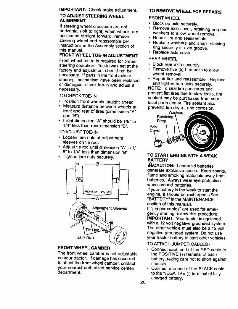
TO REMOVE WHEEL FOR REPAIRS
FRONT WHEEL
• Block up axle securely.• Remove axle cover, retaining ring and
washers to allow wheel removal.• Repair tire and reassemble.
• Replace washers and snap retainingring securely in axle groove.
• Replace axle cover.
REAR WHEEL
• Block rear axle securely.• Remove five (5) hub bolts to allow
wheel removal.
• Repair tire and reassemble. Replaceand tighten hub bolts securely.
NOTE: To seal tire punctures andprevent flat tires due to slow leaks, tiresealant may be purchased from yourlocal parts dealer. Tire sealant alsoprevents tire dry rot and corrosion.
WashersRetainingRing'
AxleCover
TO START ENGINE WITH A WEAKBA'I-rERY
_CAUTION: Lead-acid batteries
generate explosive gases. Keep sparks,flame and smoking materials away frombatteries. Always wear eye protectionwhen around batteries.
If your battery is too weak to start theengine, it should be recharged. (See"BAI-I'ERY" in the MAINTENANCE
section of this manual).If "jumper cables" are used for emer-gency starting, follow this procedure:IMPORTANT: Your tractor is equippedwith a 12 volt negative grounded system.The other vehicle must also be a 12 volt
negative grounded system. Do not useyour tractor battery to start other vehicles.
TO ATFACH JUMPER CABLES -
• Connect each end of the RED cable to
the POSITIVE (+) terminal of eachbattery, taking care not to short againstchassis.
• Connect one end of the BLACK cableto the NEGATIVE (-) terminal of fullycharged battery.
26
• Connectthe otherend of the BLACKcableto goodCHASSISGROUND,awayfrom fueltank and battery.
TO REMOVE CABLES, REVERSEORDER -• BLACK cable first from chassis and
then from the fully charged battery.
• RED cal: _,,J,astfrom bot_lbatteries. ,,"Positive"(+)J v(e/
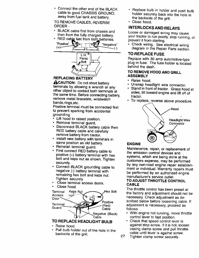
REPLACING BATTERY
_ILCAUTION: Do not short batteryterminals by allowing a wrench or anyother object to contact both terminals atthe same time. Before connecting battery,remove metal bracelets, wristwatchbands,rings,etc.Positive terminal must be connected first
to prevent sparking from accidentalgrounding• Lift hood to raised position.• Remove terminal guard.• Disconnect BLACK battery cable then
RED battery cable and carefullyremove battery from tractor.
• Install new battery with terminals insame position as old battery.
• Reinstall terminal guard.• First connect RED battery cable to
positive (+) battery terminal with hexbolt and keps nut as shown. Tightensecurely,
• Connect BLACK grounding cable tonegative (-) battery terminal withremaining hex bolt and keps nut.Tighten securelyClose terminal access doors.Close hood.
Terminal Keps N_,j,.,,-_-,._ex BoltAccess _::" ........"T'_-.- _ .-_f_Door _"_ _k. _ Y
"_ _ PositiveTerminal __ (Red)
Guard _ Cable"_1 _Negative (Black)
4,'_,__h,D," CableTO REPLACE HEADUGHT BULB
• Raise hood.• Pull bulb holder out of the hole in the
backside of the grill.
• Replace bulb in holder and push bulbholder securely back into the hole inthe backside of the grill.
• Close hood.
INTERLOCKS AND RELAYS
Loose or damaged wiring may causeyour tractor to run poorly, stop running, orprevent it from starting.• Check wiring. See electrical wiring
diagram in the Repair Parts section.
TO REPLACE FUSE
Replace with 30 amp automotive-typeplug-in fuse. The fuse holder is locatedbehind the dash.
TO REMOVE HOOD AND GRILLASSEMBLY
• Raise hood.
• Unsnap headlight wire connector.• Stand in front of tractor. Grasp hood at
sides, tilt toward engine and lift off oftractor.
• To replace, reverse above procedure.
Headlight WireConnector
27
ENGINE
Maintenance, repair, or replacement ofthe emission control devices and
systems, which are being done at thecustomers expense, may be performedby any non-road engine repair establish-ment or individual. Warranty repairs mustbe performed by an authorized enginemanufacturer's service outlet.TO ADJUST THROTTLE CONTROLCABLE
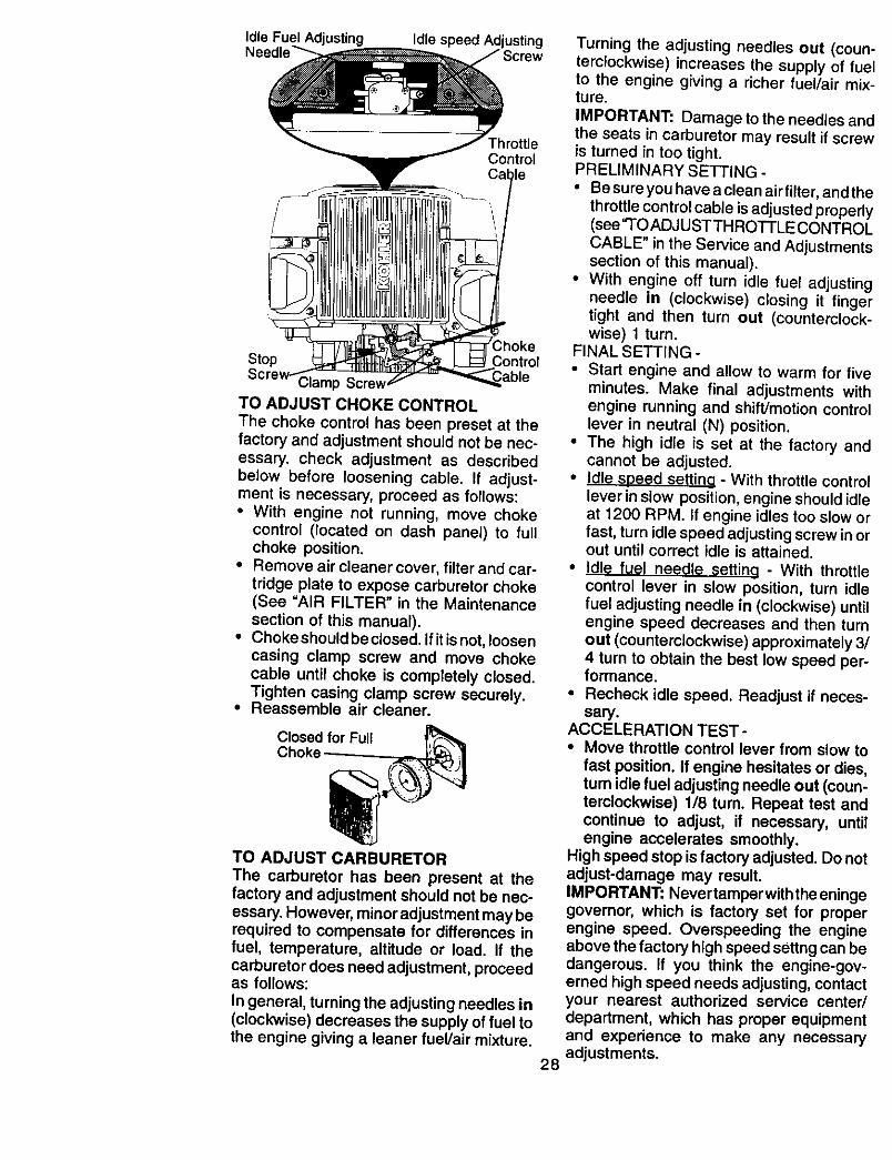
The throttle control has been preset atthe factory and adjustment should not benecessary. Check adjustment as de-scribed below before loosening cable. Ifadjustment is necessary, proceed asfollows:• With engine not running, move throttle
control lever to fast position.• Check that speed control lever is
against stop screw. If it is not, loosencasing clamp screw and pull throttlecable until lever is against screw.Tighten clamp screw securely.
Idle Fuel Adjusting Idle speed Adjusting
ThrottleControl
Stop Control
Clamp ScrevTO ADJUST CHOKE CONTROL
The choke control has been preset at thefactory and adjustment should not be nec-essary, check adjustment as describedbelow before loosening cable. If adjust-ment is necessary, proceed as follows:• With engine not running, move choke
control (located on dash panel) to fullchoke position.
• Remove air cleaner cover, filter and car-
tridge plate to expose carburetor choke(See "AIR FILTER" in the Maintenancesection of this manual).
• Choke should be closed. If it is not, loosencasing clamp screw and move chokecable until choke is completely closed.Tighten casing clamp screw securely.
• Reassemble air cleaner.
Closed for FullChoke
TO ADJUST CARBURETOR
The carburetor has been present at thefactory and adjustment should not be nec-essary. However, minor adjustment may berequired to compensate for differences infuel, temperature, altitude or load. If thecarburetor does need adjustment, proceedas follows:
In general, turning the adjusting needles in(clockwise) decreases the supply of fuel tothe engine giving a leaner fuel/air mixture.
Turning the adjusting needles out (counterclockwise) increases the supply of fueto the engine giving a richer fuel/air mixture.
IMPORTANT: Damage to the needles an,the seats in carburetor may result if screvis turned in too tight.PRELIMINARY SETTING -
• Be sure you have a clean air filter, and th,throttle control cable is adjusted properl!(see "TO ADJUSTTHROTTLE CONTROlCABLE" in the Service and Adjustment_section of this manual),
• With engine off turn idle fuel adjustin_jneedle in (clockwise) closing it fingeltight and then turn out (counterclock-wise) 1 turn.
FINAL SETTING -
• Start engine and allow to warm for fiveminutes. Make final adjustments withengine running and shift/motion centrelever in neutral (N) position.
• The high idle is set at the factory antcannot be adjusted.
• Idle soeed setting - With throttle centrelever in slow position, engine should idl_at 1200 RPM. If engine idles too slow elfast, turn idle speed adjusting screw in o=out until correct idle is attained.
• Idle fuel needle settina - With throttlecontrol lever in slow position, turn idlefuel adjusting needle in (clockwise) untilengine speed decreases and then turnout (counterclockwise) approximately 3/4 turn to obtain the best low speed per-formance.
• Recheck idle speed. Readjust if neces-sary.
ACCELERATION TEST -• Move throttle control lever from slow to
fast position. If engine hesitates or dies,turn idle fuel adjusting needle out (coun-terclockwise) 118 tum. Repeat test andcontinue to adjust, if necessary, untilengine accelerates smoothly.
High speed stop is factory adjusted. Do notadjust-damage may result.IMPORTANT: Never tamper with the eningegovernor, which is factory set for properengine speed. Overspeeding the engineabove the factory high speed settng can bedangerous. If you think the engine-gov-erned high speed needs adjusting, contactyour nearest authorized service center/department, which has proper equipmentand experience to make any necessaryadjustments.
28

Immediately prepare your tractor forstorage at the end of the season or if thetractor will not be used for 30 days ormore.• IL CAUTION" Never store the tractorwith gasoline in the tank inside abuilding where fumes may reach anopen flame or spark. Allow the engine tocool before storing in any enclosure.TRACTOR
Remove mower from tractor for winter
storage. When mower is to be stored fora period of time, clean it thoroughly,remove all dirt, grease, leaves, etc. Storein a clean, dry area.• Clean entire tractor (See "CLEANING"
in the Maintenance section of this
manual).• Inspect and replace belts, ff necessary
(See belt replacement instructions inthe Service and Adjustments section ofthis manual).
• Lubricate as shown in the Mainte-nance section of this manual.
• Be sure that all nuts, bolts and screwsare securely fastened. Inspect movingparts for damage, breakage and wear.Replace if necessary.
• Touch up all rusted or chipped paintsurfaces; sand lightly before painting.
BATTERY
• Fully charge the battery for storage.• After a period of time in storage,
battery may require recharging.• To help prevent corrosion and power
leakage during long periods ofstorage, battery cables should bedisconnected and battery cleanedthoroughly (see '3"0 CLE.AN SAT[ERYAND TERMINALS" in the Maintenance
section of this manual).• After cleaning, leave cables discon-
nected and place cables where theycannot come in contact with batteryterminals.
• If battery is removed from tractor forstorage, do not store battery directly onconcrete or damp surfaces.
ENGINEFUELSYSTEM
IMPORTANT: It is important to preventgum deposits from forming in essential warm.fuel system parts such as carburetor, fuelfilter, fuel hose, or tank during storage. 29
Also, experience indicates that alcohol
blended fuels called gasohol or usingethanol or methanol) can attract moisturewhich leads to separation and formationof acids during storage. Acidic gas candamage the fuel system of an enginewhile in storage.• Drain the fuel tank.
• Start the engine and let it run until thefuel lines and carburetor are empty.
• Never use engine or carburetorcleaner products in the fuel tank orpermanent damage may occur.
• Use fresh fuel next season.
NOTE: Fuel stabilizer is an acceptablealternative in minimizing the formation offuel gum deposits during storage. Addstabilizer to gasoline in fuel tank orstorage container. Always follow the mixratio found on stabilizer container. Run
engine at least 10 minutes after addingstabilizer to allow the stabilizer to reach
the carburetor. Do not drain the gas tankand carburetor if using fuel stabilizer.ENGINEOIL
Drain oil (with engine warm) and replacewith clean engine oil. (See "ENGINE" inthe Maintenance section of this manual).CYLINDER(S)
• Remove spark plug(s).• Pour one ounce of oi! through spark
plug hole(s) into cylinder(s).• Turn ignition key to "START" position
for a few seconds to distribute oil.
• Replace with new spark plug(s).OTHER
• Do not store gasoline from one seasonto another.
• Replace your gasoline can if your canstarts to rust. Rust and/or dirt in yourgasoline will cause problems.
• If possible, store your tractor indoorsand cover it to give protection fromdust and dirt.
• Cover your tractor with a suitableprotective cover that does not retainmoisture. Do not use plastic. Plasticcannot breathe which allows conden-sation to form and will cause yourtractor to rust.
IMPORTANT: Never cover tractor while
engine and exhaust areas are still

TROUBLESHOOTING CHART
PROBLEM CAUSE
Will not start
IHard to staM
Enginewillnot turn over
i i
CORRECTION
• Out offuel.Engine not "CHOKED"properly.Engine flooded.
• Bad spark plug.• Dirty air filter.• Dirty fuel filter.• Water in fuel.
• Loose or damaged.wiring
• Carburetor out ofService adjustment.
• Engine valves outof adjustment.
• Dirty air filter.• Bad spark plug.• Weak or dead battery.• Dirty fuel filter.• Stale or dirty fuel.
• Loose or damagedwiring.
• Carburetor out ofadjustment.
• Engine valves outof adjustment.
Clutch/brake pedalnot depressed.
• Attachment clutchis engaged.Weak or dead battery.Blown fuse.
• Corroded batteryterminals.Loose or damagedwiring.Faulty ignition switch.Faulty solenoid.or starter.
• Faulty operatorpresence switch(es),
Fill fuel tank.See '3-0 START ENGINE"in Operation section.Wait several minutes beforeattempting to start,Replace spark plug.Clean/replace air filter.Replace fuel filter.Drain fuel tank and carburetor, Irefill tank with fresh gasolineand replace fuel filter.Check all wiring.
See "To Adjust Carburetor" inAdjustments section.Contact an authorized servicecenter/department.
• Clean/replace air filter.Replace spark plug.Recharge or replace battery.Replace fuel filter.Drain fuel tank and refill with
fresh gasoline.• Check all wiring.
See "To Adjust Carburetor" inService Adjustments section.Contact an authorized servicecenter/department.
• Depress clutch/brake pedal.
Disengage attachment clutch.
• Recharge or replace battery.• Replace fuse.
Clean battery terminals.
• Check all wiring.
• Check/replace ignition switch.Check/replace solenoid orstarter.
• Contact an authorized servicecenter/department.
3O
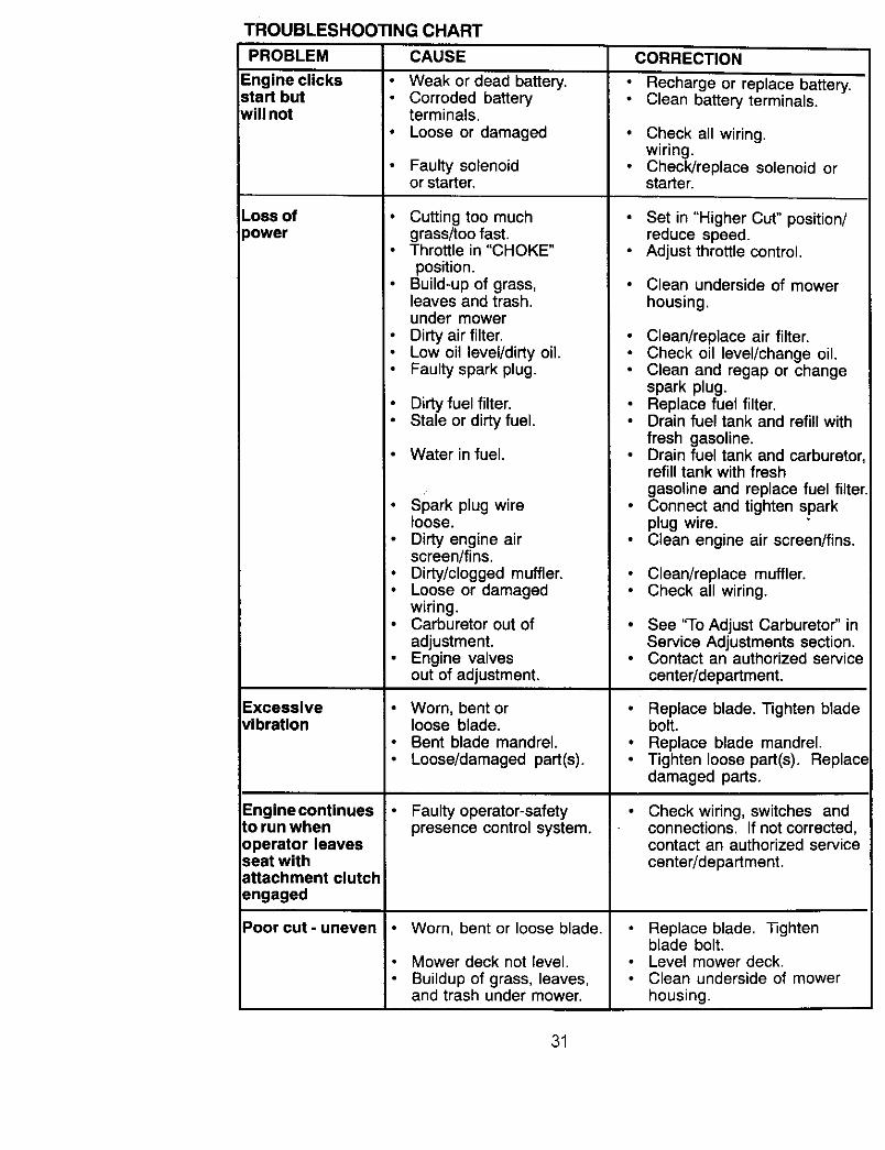
TROUBLESHOOTING CHART
PROBLEM CAUSE
Engine clicks Weak or dead battery.start but Corroded batterywill not terminals,
• Loose or damaged
Loss of:)ower
Excessive_ibration
Engine continuesLorun whenoperator leavesseat withattachment clutchangaged
Poor cut - uneven
Faulty solenoidor starter.
• Cutting too muchgrass/too fast.Throttle in "CHOKE"position.
Build-up of grass,leaves and trash.under mowerDirty air filter.Low oil level/dirty oil.Faulty spark plug.
Dirty fuel filter.Stale or dirty fuel.
Water in fuel.
• Spark plug wireloose.Dirty engine airscreen/fins.
• Dirty/clogged muffler.• Loose or damaged
wiring.• Carburetor out of
adjustment.Engine valvesout of adjustment.
Worn, bent orloose blade.Bent blade mandrel.Loose/damaged part(s).
Faulty operator-safetypresence control system.
Worn, bent or loose blade.
Mower deck not level.Buildup of grass, leaves,and trash under mower.
CORRECTION
Recharge or replace battery.Clean battery terminals.
Check all wiring.wiring.Check/replace solenoid orstarter.
Set in "Higher Cut" position/reduce speed.Adjust throttle control.
Clean underside of mowerhousing.
Clean/replace air filter.Check oil level/change oil.Clean and regap or changespark plug.Replace fuel filter.Drain fuel tank and refill withfresh gasoline.Drain fuel tank and carburetor,refill tank with freshgasoline and replace fuel filter.Connect and tighten sparkplug wire.Clean engine air screen/fins.
• Clean/replace muffler.• Check all wiring.
• See "To Adjust Carburetor" inService Adjustments section.
• Contact an authorized servicecenter/department.
• Replace blade. Tighten bladebolt.
• Replace blade mandrel.• Tighten loose part(s). Replace
damaged parts.
Check wiring, switches andconnections. If not corrected,contact an authorized servicecenter/department.
Replace blade. Tightenblade bolt.Level mower deck.Clean underside of mowerhousing.
31

TROUBLESHOOTING CHARTCAUSEPROBLEM
Poor cut - uneven(Cont.)
Mower blades willnot rotate
Poor grassdischarge
Headlight(s) notworking
Battery will notcharge
Engine "backfires"when turningengine "OFF"
Bent blade mandrel.
Clogged mower deckvent holes from buildup ofgrass, leaves, and trasharound mandrels.
Obstruction in clutchmechanism.
Worn/damaged mowerdrive belt.Frozen idler pulley.Frozen blade mandrel.
Engine speed too slow.
Travel speed too fast.• Wet grass.
Mower deck not level.Low/uneven tire airpressure.
• Worn. bent or looseblade housing.Buildup of grass, leavesand trash under mower.Mower drive belt worn,
• Blades improperlyinstalled.
• Improper blades used.
Clogged mower deckvent holes from buildup ofgrass, leaves, and trasharound mandrels.
Switch is "OFF".• Bulb(s) burned out.
Faulty light switch.Loose or damagedwiring.Blown fuse,
Bad batterycell(s).Poor cable connections.Faulty regulator(if so equipped).Faulty alternator.
Engine throttle controlnot set at "SLOW"position for 30seconds beforestopping engine.
CORRECTION
• Replace blade mandrel.Clean around mandrels toopen vent holes.
Remove obstruction.
Replace mower drive belt.
• Replace idler pulley.• Replace blade mandrel.
Place throttle control in"FAST" position.Shift to slower speed.Allow grass to drybefore mowing.Level mower deck.
Check tires for proper airpressure.Replace/sharpen blade.Tighten blade bolt.Clean underside of mower
Replace mower drive belt,• Reinstall blades sharp edge
down.
Replace with blades listed inthis manual.
• Clean around mandrels toopen vent holes.
• Turn switch "ON".Replace bulb(s).Check/replace light switch.Check wiring and connec-tions.
• Replace fuse,
Replace battery.Check/clean all connections.Replace regulator.
• Replace alternator.
• Move throttle control to"SLOW" positionand allow to idle for 30seconds before stoppingengine.
32

SCHEMATIC
TRACTOR -- MODEL NUMBER 917.273050
BATTERY SOLENOID
,
FUSE30AMP. _lr= f._ _ ; ,Lu -__j-
AMMETER i i STARTER...... = _ITE I)
wH,_ I C G i _ BUCK I
: , ,_,WHITE i i
BLACK F H _l I ELECTRIC CLUTCH
_NITION I A : '
i _ t- aLACK
I i
° I
L ........
CLUTCH/BRAKEL ......... i
PTO (DISENGAGED)
SEAT SWITCH
(NOT OCCUPIED)
, I_ I _LA°_ !!
I SPARK PLUGSGAP
J---'_ (2 PLUGS
_ ON TWIN CYL. ENGINES)
FUEL SHUT-OFFSOLENOID
_ RPMRELAY
PTO SWITCHPOSITION CIRCUIT
OFF C+GIB+HON C+FrB+ErA+D
• !
2e VOLTS AC @ 3600 RIM {REGULATOR DISCONNECTED)
HEADLIGHTS
GFC
IGNmON SWITCH REMOVABLE NON-REMOVABLECONNECTIONS CONNECTIONS H B
ENGINE CONNECTOR TRAC.T(_RCONNECTORREGULA OR N NE ...........(PURPLEWIRE, SHORTING IGNITION SWITCH EATTEF
WIRING INSULATED CLIPS RED WIRE) TE W RE) M FOR ENGINE _ CHARGIfSHORT'NG (REow,_NOTE: IFWlRING INSULATED CARBURETOR ll_!_][_ll (E_'OKW'RE)_ _h--llCUPBW_REREMOVED_ORSOLENO,O_ _RED WIRE. OIL SENTRY OIL SENTRY SWITCHSERVICING OF UNIT, THEY _LUE W RE) REEN WIRE) OPT ON +12VSHOULD BE REPLACED TO ELLOWWIRE _ (BLUE WJPROPERLY SECURE YOUR "_ t3GH'f PKG.)
WIRING.
33

TRACTOR-- MODEL NUMBER 917.273050ELECTRICAL
22
26
29
t
I
J
34

ELECTRICAL
TRACTOR -- MODEL NUMBER 917.273050
KEYPARTNO. NO. DP.SCRIPI1ON
1 144927 Battery2 74760412 Bolt Hex Head 1/4-20 x 3/48 7603J Tray, Battery10 145211 Bolt 1/4.20 x 7.5 Zinc11 150109 Hold down Battery Dash Mount12 145769 Nut Push Nylon 1/4"16 153664 Switch Interlock Push-In19 STD551125 Washer, Lock 1/420 73350400 Nut, Jam Hex 1/4-2021 166184 Harness Socket Ught W/4152J22 4152J Bulb Ught24 4014J Cable, Battery25 146686 Cable, Battery26 108824X Fuse27 73510400 Nut Keps Hex 1/4.20 Unc28 157899 Cabte, Ground29 160784 Switch, Plunger30 163968 Switch, Ign33 140403 Key, Ignition40 166176 Harness Ign.41 17720408 Screw 1/4-20 x 1/242 131563 Cover, Terminal43 145673 Solenoid45 122822X Ammeter50 154963 Switch, PTO52 141940 ProtectionWire Loop81 109748X Retay Asm.83 163996 BulbholderAsm. Incan descent
NOTE: All component dimensionsgiven in U. Sinches 1 Inch = 25/4 mm
35

TRACTOR -- MODEL NUM BER 917.273050
CHASSIS AND ENCLOSURES
_138
37
17 144
52
28
21 17
I
17
147
1508
_ 122
_7 17
_0 42
122
6763
36
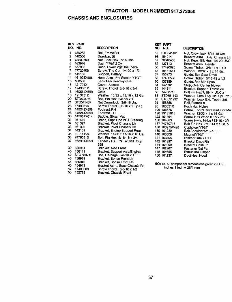
TRACTOR-- MODEL NUMBER 917.273050
CHASSIS AND ENCLOSURES
KEY PART KEY PARTNO. NO. DESCRIPTION NO. NO. DESCRIPTION
1 150253 RaiI, FrameRH 52 STD5414312 140506 Drawbar, Gt 56 1549144 73800700 Nut, Lock Hex 7/16 Uric 57 736404005 163976 Dash YTGT 2 Cyl 58 1371136 157882 Dash, LowerVgtOnePiece 60 174906207 17720408 Screw, Thd Cut 1/4-20 x 1/2 63 191316148 145166 Support, Battery 67 156973
14 161023X558 Hood Asm., Pnt Stealth YTGT 68 1749050815 160568 Lens Asm Headlight Bar 70 13715916 121794X Cover, Access 84 14299217 17490612 Screw, Thdrol 3/8-16x 3/4 85 14491118 160564X558 Gdlle 86 7476071619 19131312 Washer 13/32 x 13/16 x 12 Ca. 88 STD55114320 STD523710 Bolt, Fin Hex 3/8-16 x 1 90 STD55123721 STD541437 NutCrownlock 3/8-16Unc 91 15658623 17490616 ScrewThdrol 3/8-16 x 1 Ty-Tt 95 105531X24 145243X558 Footrest, RH 106 13877628 145244X558 Footrest, LH 120 1913161630 145051X014 Saddle, Slkscr Vgt 122 16146431 161419 Brace, Supt 1*pc VGT Steering 130 16486332 161327 Bracket, Pivot Chassis Lh 137 7478071633 161326 Bracket, Pivot Chassis Rh 138 163975X42834 142131 Bracket, Engine Support Rear 139 16133035 19111116 Washer 11132x11116x16Ga, 140 16380636 74780512 Bott, Fin Hex 5/16-18 x 3/4 141 16380537 163981X558 FenderYTGTPNTWO/SHCup 142 161897
558 144 16190039 136961 Bracket, Axle Front 147 16296740 156111 Bracket, Support Axle/Engine 148 16465542 STD533710 Bolt, Carhage 3/8-16 x 1 150 16123743 136939 Bracket, Spnsn Front Lh
44 136940 Bracket, Spnsn Front Rh NOTE: All componentdimensions given in U. S.45 154913 Bracket Asrn., Susp Chassis Rh inches 1 inch = 25/4 mm47 17490608 Screw Thdrol. 3/8-16 x 1/250 152728 Bracket, Chassis Front
Nut, Crownlock 5/16-18 UncBracket Asm., Susp Chassis LhNut, Keps, BIk Hex 1/4-20 UNCBracket Asm., FenderScrew ThdroL 3/8-16 x 1-1/4Washer 13/32 x 1 x 14 Ca.Guide, Belt Gear DriveScrew ThdroL 5/16-18 x 1/2Guide, Belt Mid SpanStop, Over Center MowerBracket, Support TransaxleBolt Fin Hex 7/16-14 UNC x 1Washer, Lock Hvy Hlcl Spr 7/16Washer, Lock Ext. Tooth 3/8Rail, Frame LhPush Nut, NylonScrew, Thdrol Hex Head Zinc MwTWasher 13/32 x 1 x 16 Ga.Screw Hex Wshd 8-18 x 7/8Screw Hwhd Hi-Lo #13-16 x 3/4Bolt Fin Hex 7/16-14 x 1 Gr. 5Cupholder YTGTBolt Shoulder 5/16-18 TTMagnetYTGTStdker Plate YTGTBracket Dash RhBracket Dash LhFastener Nut PalExtrusion BumperDuct Heat Hood
37

TRACTOR -- MODEL NUMBER 917.273050GROUND DRIVE
39
28\
9
27
10_.
69
3
36i.... 37 6
29
62
38

TRACTO R -- MODEL NUMBER 917.273050
GROUND DRIVE
KEY PART KEY PARTNO. NO. DESCRIPTION NO. NO.
1 9858M1 Key, Woodruff 37 121749)(3 7563R Washer, Thrust, Axle 38 1500354 17490508 Screw Thdrol 5/16-18 x 3/4 39 743210165 STD541437 Not, Crownlock 3/8=16 40 5304J6 STD561210 Pin, Cotter 41 736610007 149176 WheeI, HubAssembly 42 8883R8 12000034 Klip,Ring 46 1451709 140080 Bolt, Hub 47 138228
10 142509 Disc, Brake 48 7211061211 136927 Yoke, Brake Disc 50 13149412 73750800 Nutlock 1/2-20 Unf 51 STD54143713 139419 Washer, Special 52 13912314 138901 Bushing 53 207J15 STD551037 Wahser 13/32x13/16x16Ga. 54 16159016 143012 Set, Screw 1/4-28x3/4 55 105706X17 126909X Spring 56 13715318 137104 Lever, BraKe 57 14175619 136926 Cam, Brake Disc 59 122.253X21 23260412 Screw, Flat Head 1/4-28 x 3/4 60 122,?.68X22 633A109 Gearshift, Lever Assembty 61 13752423 106932)( Knob 62 STD55114324 136925 Support, Puck Brake 63 7476072025 136923 Puck, Brake Top 64 15475226 137552 Spring, Return 65 6760927 17490528 Screw, Hex Wsh Thd. 66 140296
5/16-18x 1-3/4 67 1913131228 STD541237 Nut, Hex Jam 3/8-16 68 5142H29 137213 Brake, Rod 69 13632730 19131616 Washer 13/32 x 1 x 16 Ga. 117 7390060034 124236X Cap, Plunger35 137648 Rod, Parking Brake36 149412 Spring, Drive Ground
DESCRIPTION
Washer 25/32 x %1/4 x 16 Ga.NyllnerScrew, Fin. #10-24 x 1Actuator, interlock SwitchLocknut #10-24Cover, PedalRetainer, SpringClutch RodBolt, Carriage 3/8-16 x 1-1/2 Gr. !Pulley, Idler, FiatNut, Crownlock 3/8-16 UNCPulley, Idler, GroovedWasher, HardenedClutch, Arm AssemblyBearing, IdlerV-BeltBracket, Shift Rod, Hi-LoShift Rod, Hi-LoSpring Clip, Connecting LinkPulley,TransaxteWasher, Lock 7/16Bert, Fin Hex 7/16-14 x 1-1/4Shaft, Clutch/Brake PedalBolt, ShoulderWasher, HardenedWasher, FlatPin, RollHub, CoverNut, Lock Fig. 3/8-16 Unc
NOTE: All componentdimensions given in U. S.inches 1 inch = 25/4 mm
39

STEERINGTRACTOR -- MODEL NUMBER 917.273050
16
\
40

STEERING
TRACTOR -- MODEL NUMBER 917.273050
KEY PARTNO. NO. DESCRIPTION
1 159944X4282 1370943 6855M4 1618495 1618486 6266H7 121748X8 120000299 121232X
10 7478104411 13651812 7390100013 121749)(.14 STD55113715 STD54153716 14510317 13734718 13715519 15601120 16388721 15994522 15510523 15292725 STD52371026 159946X42827 3366R28 1749061229 104239X30 1200003431 13813632 1911161033 STD55113134 STD52310735 13805936 13715637 7336060038 109850X39 737006o0040 109851X41 15524642 1749050844 16013545 19132411
Wheel, SteeringAxle Asm., FrontFitting, GreaseSpindle Asm, LHSpindleAsm., RHBeadng, Race ThrustHardenWasher 25/32 x 1-5/8 x 16 Ga.Ring,Klip#T5304-75Cap, SpindleBolt, Fin Hex 5/8-11 x 2-3/4Spacer Bearing Axle FrontNut, Lock Flange 5/8-11 UricWasher 25/32 x 1-1/4 x 16 Ga.Washer, Lock HW HlClSpr 3/8Nut, Lock Center 3/8-24 UNFShaft Asm., SteeringRod Asm., Tie Ball J Ball Vgt (inc. Key No. 36-40)Draglink, Ball Joint Solid VgtSupport Asm., Steering VgtBoot, SteeringAdapter, Wheel SteeringBushing, Strg. BIkScrewBolt, Fin Hex 3/8-16 x 1 Gr, 5Cap, Wheel SteeringBearing, CoL Strg.Screw, Thrdrol 3/8-16 x 3/4Bearing,FlangeRing, Klip Truarc #5304-75Bushing,NylinerSoapWasher 11/32 x 1 x 10 Ga.Washer, Lock Hvy Hlcl Spr 5/16Bolt, Hex Hd 5/16-18 x 3/4Gear, Sector SteeringTie RodJam Nut RH ThreadJoint Asm. Ball RH ThreadJam Nut LH ThreadJoint Asm. Ball LH ThreadBracket Switch Interlock VGT 97ScrewThdrol 5/16-18 x 1/2 TytExtension, SteeringW_,sher 13132x 1-1/20 x 11 Ga,
NOTE: All component dimensions given in U. S.inches 1 inch = 25/4 mm
41

ENGINETRACTOR-- MODEL NUMBER 917.273050
_12 r
_3
10
_169
64
_j74
_ ss_s
_ d_"'_'_ 19 7
54
38
29
\I SPARK ARRESTER KIT ]
42

ENGINE
TRACTOR-- MODEL NUMBER 917.273050
KEY PARTNO. NO. DESCRIPTION
1 Engine (See Breakdown)Kohler Model No. CV20S-65551
2 161063 Muffler Side 1-1/4"985 13200300 Elbow STD 90 Degree 3/8- 18 NPT7 151396 Muffler Asm Guard8 121361X Pulley V-Idler9 t50828 Keeper Asm. Belt Engine
10 1054,32X Bushing11 140923 Clutch Etectric12 143996 Pulley Engine VGT Elect Clutch15 151346 Tank Fuel Rear 3.50 YUGt 9616 109227)( Pad Spacer17 106082X Pad Spacer18 161493 Cap Asm Fuel W/Gauge19 13290300 Plug Oil Drain (See Engine Breakdown)20 164067 GootrolThroffle21 164863 Screw Hwhd Hi-Lo #13-16 x 3/422 164415 ControlChoke24 STD551237 Washer Ext Tooth 9/825 73920600 Nut Keps 3/8 - 24 UNF26 3645J Bushing27 139277 StemTank Fuel28 7834R Fuel Line29 132920 Spark Arrester Kit33 STD541437 Nut Lock Hex w/Ins. 3/8 - 1635 10010500 Washer Split37 123487)( ClampHose38 74780624 Bolt Fin Hex 3/8 - 16x 1-1/239 17490636 ScrewTr 3/8-16x2-1/4UNC40 17490664 Screw'i-r 3/8-t6 x 4 UNC41 126197X Washer 1ol/20D X 15/32 ID X .25042 STD551143 Washer Lock 7/1643 150280 Bo)tHex 7/16 - 20 X 4 - 1/4 Ga 545 128861 Nut Flange 1/4-20 Starter Nut47 142040 Spacer Engine48 19132007 Washer 13/32 x 1-1/4 x 7 Ga.51 161231 Manifold Pipe VGT CV 1-1/4"54 19131414 Washer Flat 13/32 x 7f8 x 14 Ga,55 13280336 Nipple Pipe 4-1/264 17490612 Screw Thdrot 3/8-t 6 x 3/4 Ty-TL"65 19131614 Washer 13/32 x 1 x 14 Ga.69 24-041-02 Gasket74 162295 Elbow Street Brass80 M73030800 Nut Flaege
NOTE: All component dimensionsgiven in U. S.inches 1 inch = 25/4 mm
43

TRACTOR-- MODEL NUMBER 917.273050
SEATASSEMBLY
19
12
21
KEY PARTNO. NO.
1 1401242 1405513 1406754 127018X5 1450066 STD5414377 124181X6 150176
10 15592512 121246X13 121248X14 72050412
3
DESCRIPTION
SeatBracket, Pivot SeatStrap, FenderBolt, Shourder 5/16.18x.62Clip, Push In, HingedNut, Crownlock 3/8-16 UncSpring, Seat CprsnBolt 5/16-18 Unc x 3/4 w/SemsPan, SeatBracket, MountingSwitchBushing, SnapBolt, Carriage 1/4-20X 1-1/2
KEY PARTNO. NO.
15 121249X16 123740X17 123976X18 1917191219 120068X20 124238X21 15323622 STD54.1431
DEBCRIP'nON
Spacer, SplitSpdng,CprsnNut, Lock 1/4 Lge Fig G[. 5Washer 17/32 x 1-3/16 x 12 Ga.Knob, Seat 1/2-13 UncCap, Spdng SeatBolt, Shoulder 5/16-18Nut, Crown_ock 5/16-18 Uric
NOTE: All component dimensions given inU. S.inches 1 inch = 25/4 mm
44

DECALS
TRACTOR- MODEL NUMBER 917.273050
73 1
10
5 12
8
1514
11
KEY PARTNO. NO.
1 1632652 164O853 1639164 1639175 149516
6 1336447 1671666 1647579 163204
10 15643911 4900J
DESCRIPTION
Decal, Dash PanelDecat,DashDecal, Hood RH Craftsman "Decal, Hood LH CraftsmanDecal, Battery DNGR/PSNENGAsroDecal, MaintenanceDecal, FenderDecal, EngineDecal, Fender CraftsroanDecal, Fender DangerDecal, Clutch/Brake
KEY PARTNO. NO.12 14604713 16488414 16039715 16717519 13804723 106202X- - 138311
-- 157199-- 167109-- 167110
DESCRIPTION
Decal, V-Belt Dr SchDecal, BlowerHousingDecal,V-Belt ScheroDecal, ReplcDecal, BatteryReflector,TaillightDecal, Handle Lft HeightAdjust(Lift Handle)Pad, FootrestOwner's Manual, EnglishOwner's Manual, Spanish
WHEELS AND TIRES
t -....___...,3
74
10
g
KEY PARrNO. NO.
1 591922 651393 106228X4274 81341"t5 106230X6 278H7 9040t-I
8 104757X8 9 105588X
10 7154J11 106227X42712 6856M-- 144334
DESCRIPTION
Cap ValveTireStem ValveRimAsro FrontTube, Front (Service Item Only)Tire, FrontFittingGrease (Front Wheel Onl'BearingFlange (FrontWheelOnly)Cap Axle (FrontWheel Only)Tire RearTube Real (Service Item Only)Rim Asm RearFittingGreaseSealant, Tire ( 10 oz. Tube)
NOTE: All componentdimensionsgiven in U. S.inches 1 inch = 25/4 mro
45
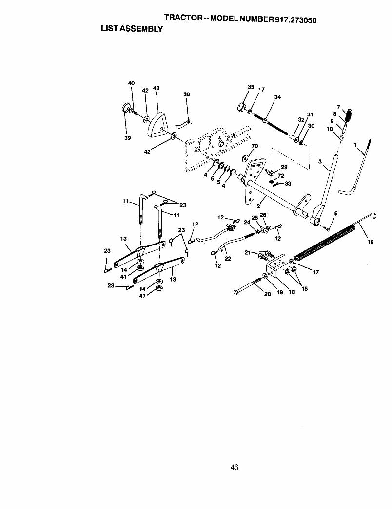
TRACTOR -- MODEL NUMBER 917.273050LIST ASSEMBLY
40
39
42
35 17
70
34
12 _ 24 \ \
13 I 23 . 1_2
_2__ 20 19 18
12
16
46

TRACTOR-- MODEL NUMBER 917.273050
LIST ASSEMBLY
KEY PARTNO. NO. DESCRIPTION
1 121006X RodAsm., Lever2 159187 Shaft Asm., Lift Vgt3 159189 Lever Asm., Lift Rh4 12000022 E-RingTruarc#5133-875 19292016 Washer 29/32 x 1-1/4 x 16 Ga.6 74780624 Bolt, Fin Hex 3/8-16 x 1-1/27 125631X Grip, Handle Fluted8 122365X Button, Plunger9 122364X Plunger, Button
10 2876H Spring 2-1/8"11 146704 Link Lift12 163552 Retainer, Spring13 139868 Arm, SuspensionVgt14 140302 Bearing15 STD541437 Nut, Crownlock 3/8-16 Unc16 674A247 Spring Asm., Assist Uft17 S_1237 Nut, Hex Jam 3/8-16 Unc18 143363 Bracket, Spring Assist19 STD551037 Washer 13/32x13/16x16Ga.20 5328J Bolt, Adjust Spring Assist21 STD523710 Bolt, Fin Hex 3/8-16 x 1
127218 Link, Front23 STD624008 Retainer, Spring24 73350800 Nut, JamHex 1/2-13Unc25 130171 Trunnion26 STD541437 Nut, Crownlock 1/2-13 Unc29 150233 Trunnion, lnfin Height30 110807X Nut, Special31 STD551037 Washer 13/32 x 5/8 x 16 Ga.32 137150 Spring, Compression Inf Hgt33 STD560907 Pin, Cotter 3/32 x 1/234 137167 Rod, Adj Lift35 138057 Knob, Inf 3/8-16 Unc38 155097 Pointer, Height Indicator39 123935X Plug, Hole40 17490512 Screw Hex Wsh 5/16-18 x 3/441 73540600 Nut, Crownlock 3/8-2442 19112410 Washer 11/32x1-1/2x10Ga.43 123934X Scale, Indicator Height70 145212 Nut Hex Flange Lock72 110452X Nut Push Phos & Oil
NOTE: All componentdimensions given in U. S.inches 1 inch = 25/4 mm
47

TRACTOR -. MODEL NUMBER 917.273050MOWER DECK
4553,
49
36
4 36
55
45
43
48
47
48
22
54
_" 1123
48

TRACTOR -- MODEL NUMBER 917.273050
MOWER DECK
KEY pART KEY PARrNO. NO. DESCRIPTION NO. NO.
1 156990 MowerDeckWetdment50 39 1314942 STD541413 Nut, Ctownlock 5/16-16 40 1365723 72110506 Bolt, Carriage 5/16-18x3/4 42 STD5.331074 7631J Runner, MowerLH 43 1364605 138457 Bracket Asm., Sway Bar 44 122.052.X6 STD624008 Retainer,Spring 45 STD5414377 130832 Arm Suspension, Rear 46 747606288 850857 Bolt 3/8-24 x 1.25 Gr. 8 Patched 47 1372009 BTD551137 Washer, Lock HW 3/8 Unplated 48 13772910 140296 Washer, Hard Blade Mower 49 136574
Vented 50 13727211 137380 Blade (3 Required) 51 13727312 129895 Bearing, Bal_ #6204 (Mandrel) 52 13924513 137553 Shaft Asm.,W/Lower Brg 53 137789
(Includes Key No. 12) 54 13957314 137152 Housing, Mandrel50"Vent 55 14495915 110485X Beering,BalIMandre_ 56 13868716 140329 Stripper, MowerVented 57 13657717 106735X Rod, Hinge 58 13395718 19111016 Washer 11/32x5/8x16Ga. 59 13764419 105304X Cap, Sleeve 60 13903120 123713X Spring, Torsion Deflector 61 13657321 137607 Bracket, Deflector 62 13394322 110452X Nut, Push 63 7211061223 110509X Sh{eld,Def_ectorMewer 64 1912141424 136320 Runner,RH 65 15183125 19111216 Washer 11/32x3/4x16Ga. 66 15600927 STD551037 Washer 13/32 x 13/t6 x 16 Ge. 67 7393060029 132823 Spacer, Spring Step Idler 99 7211061430 157722 Screw ThdrolRolUngWasher
Head 102 15339031 137266 Nut, FIgTop Lock Cntr 9/16 -- 14365132 153535 Pulley, Mandrel33 129963 Washer, Spacer Mower Vented - - 15833034 72140610 Bolt, Carriage 3/6-16 x1-1/435 72110616 Bolt, Carriage 3/8-16x236 72110609 Bolt, Carriage 3/6-t6xl Gr. 537 137166 Stiffener, Arm Idler38 156085 Keeper, Beltldler
DESCRIP13ON
Pulley, Idler F_atPulley, DrivenBo_t,Carriage 5116-18 Unc x 3,Arm, Idler SecondarySpacer, RetainerNut, Crownlock 3/8-16 UncBolt, Fin Hex 318-16 Uric x 1-3_Cover, Mandrel RHScrew, Thd Rell 1/4-20 x 5/8Cover, Mandrel LHArm, Idler PrimarySpring, SecondaryPulley, _dler V GrooveShield, IdlerV-BeLt,Mower PrimaryV-Belt, Mower SecondarySpring, PrimaryBar Asm., Wheel GaugeWheel, GaugeBolt, ShoulderPin, ClevisBracket, Wheel GaugeWasher HardenedBolt Carriage 3/8-16 x 1-1/2Washer 3/8 x 3/4 x 14 GaPulley Idler FlatMowerKeeper, Belt Idler 44/50"Nut, Centerlock 3/8-16Bolt, Carriage 3/8-16 x 1-3/4Gr. 5Washer, FeltMandrel Assembly (Includes K_Nos. 8-10, 12-15, 31 and 33)Deck Assembly - Service (Std.Deck - Order Separately All No=Rollerand GaugeWheelComponents)
NOTE: All component dimensions given in U. S.inches 1 inch = 25/4 mm
49

TRANSAXLE
TRACTOR-- MODEL NUMBER 917.273050
7
7470
73
72
41
2524
5O

TRANSAXLE
TRACTOR -- MODEL NUMBER 917.273050
KEY PART KEY PARTNO. NO. DESCRIPTION NO. NO. DESCRIPTION
1 4197R2 120000343 4199R4 4216R5 4215R6 4217R7 6256H8 74020652
9 7392M10 13726111 4985R12 6266H13 4212R14 13712515 6276H16 633A6317 8118M18 8740H119 122238X20 4218R21 6252H122 7810H23 6262H24 7393R25 992R126 13911127 4986R28 122254X29 6269H30 5855H31 139538
32 6277H33 42"25R34 7396H35 4198R36 4200R37 7395H38 16078939 139536
40 1332040041 1758052045 6271H46 1306020049 4895H50 4222R51 1529R
Axle Shaft 52 8119MRetaining Ring 53 4220RFinalDrive Gear 54 4209RDifferential Geer 55 4213RDifferential Pinion 56 4442RDifferential Carrier 57 4195RAxle Thrust Washer 58 4214RBolt, Hex Head 3/8-24 x 3-1/4 59 4194R(l"ThreadLength) 60 7528RSteel Ball 61 4208RSpring Shift Fork Detent 62 4207RShift Fork, High-LowRange 63 7398HThrust Bearing Race 64 4203R4th Reduction PinionShaft, Brake 65 4204RSnap Ring, Crescent Type 66 2898JHigh-Low Range Gears 67 12000033Needle Bearing 68 4205RSinteredlron Bearing 69 4206RShift Fork Shaft, High-Low Range 70 1370HDifferential Pinion Spacer 71 633A69Differential Pinion BushingGripco Centerlock Nut 3/8-24 72 139120Shift Fork, R.H. 73 4201ROil Seal 74 12000008Sintered Iron Bearing 75 1153RShift Fork Shaft 77 6803JShift Fork, L.H. 79 1167RShift Shaft, High-Low Range 80 73360700Oil Seal 81 6270HPressure Relief Valve 82 136984Gearcase, Reverse Idler Shaft 84 5384,.IandBearings, R.H. (includes Key 85 2978JNo.Os 17,18, 25, 33, 50, 63, 77 86 633A85and 82) 87 8739H1Dowel Pin 88 4924HNeedle Beefing 89 19151516Thrust Bearing Race4th Reduction Gear Shaft 90 110542X4th Reduction Gear Spacer 91 19181511Thrust Bearing Race 92 75JGate, Lower, ShiftGearcase and Bearings, L.H. 93 6274H(Includes Key Numbers 18, 25, 94 7602041249, 50 (2), 51 and 52) 96 159783PipePlug 1/2-14N.P.T. 97 633A109Bolt, Hex 5/16-18 UNC x 1-1/4 98 161823Oil SealPipe Plug 1/4-18 N.P.T.Needle BeerlngNeedle BearingNeedle Bearing
Needle BearingThrustBearing Race3rd Reduction Pinion, Low4th Reduction Gear3rd Reduction Pinion Spacer2nd Reduction Gear ShaftFinal Drive Pinion1st Reduction Gear Shaft1st Reduction Shaft Spacer3rd Reduction Pinion High2nd Reduction GearNeedle BearingLow Speed Gear and 2ndReduction Pinion ClusterReverse GearKey, Hi-Pro 1/8 x 17/32Klip RingIntermediate Speed GearHigh Speed GearThrust Bearing RaceIntermediate and High SpeedCluster PinionsInput ShaftLow Speed PinionE-RingReverse Idler GearNeedle BearingSealingWasherNut, Hex, Jam 7/16-20"Oil SealReverse Idler ShaftGearshift Lever, BentGearshift CapGearshift Ball Cover and PinShift Lever Guide Ball, KeyedSpringWasher 15/32 x 15/16x 16GaugeShift Mechanism SealWasher 9/16 x 15/16 x 12 GaGearshift Gate andReinforcementShift Ball Cover GasketCotter Pin 1/8 x 3/4Screw, Hex, Washer, HD.Gearshift Lever AssemblyTransaxle, 6 Speed,Complete Assembly
NOTE: All componentdimensions given in U.S.inches 1 inch = 25.4 mm
51
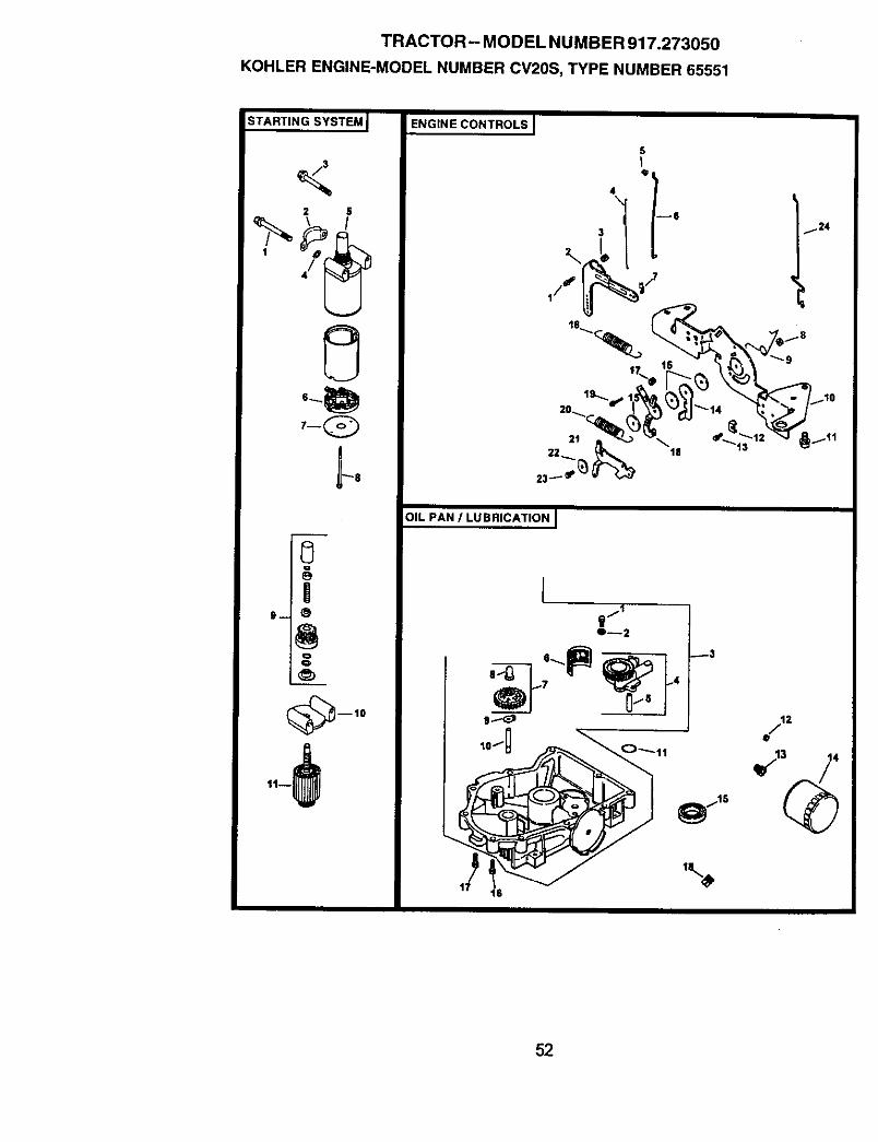
TRACTOR- MODEL NUMBER 917.273050
KOHLER ENGINE-MODEL NUMBER CV20S, TYPE NUMBER 65551
STARTING SYSTEM I
2 S
7-Q
ENGINE CONTROLS I
5I
12
23_' _
OIL PAN / LUBRICATIONJ
17
O--2
_3
2
52

TRACTOR -- MODEL NUMBER 917.273050
KOHLER ENGINE-MODEL NUMBER CV2OS, TYPE NUMBER 65551
STARTING SYSTEM OIL PAN/LUBRICATION
KEY PART KEYPARTNO. NO. DESCRIPTION NO. NO. DESCRIP'RON
1 M-0839070 Screw, hex. flange M8xl,25x702 24-096-05 Cover, pinion3 M-0839080 Screw, hex. flange MBx1.25xB04 12-468-01 Washer, plain 11/32" (3)5 25-098-05 Starter, (Includes 6-11)6 12-221-0t Kit, brush7 12-227-13 Cap8 12-211_1 Bolt, thru (2)9 12-755-54 Kit, drive
10 12-227-06 Cap, drive end11 12-170-05 Armature
ENGINE CONTROLS
KEYPARTNO. NO. DESCRIPTION
Screw, hex. flange M6x1.0x25Lever, governorNut, hex. flange M6xl.0Spring, linkageBushing, linkage retainingLinkage, throttleBushing, throttle linkageNut, hex. lock MSx0.8Spring, throttleBracket, controlScrew, hex. flange M6xl.0x16(4)Clamp, cable (2)Screw, hex. flange M5x0.8x16(3)Lever, thorttle actuatorWasher, plain 5.5 mm (3)Spring, governorNut, hex M4x6.7Lever, throttle controlScrew, hex. flange M5xO.Bx20Spring, throttle llmiterLever, chokeWasher, spring 114"Screw, hex. cap M4x0.7x25Linkage, choke
1 SM_o420252 24-090 143 M-06410604 24-089-015 25-158-086 24-079-047 25-158-118 M-05470509 24-089-03
10 24-126-5611 M-0645016
12 12-237-0113 M-0545016
14 24-090-0715 24-468-0116 24-089-1817 M-044603018 24-090-1319 M-054502020 24-089<3821 24-090-0522 41--468-0323 M-040302524 24-079-05
23
4567
89
1011121314151617
18
M-0645025
M-O63100524-199-07
24-393-0824-123-0524-162-2624-043-12
12-380-0152-448-0212-144-O224-153-08X-75-3224-136-0152-050-0252-032-0824-086-1724-086-16
X°75-10
Screw, hex. flange M6x1.0x2_(2)Washer, plain 6 mm (2)Pan, oil assembly(Includes 1,2, & 4-10)Oil pump assembly (IncludesTube, oil pickupScreen, oilKit, governor gear w/pin(Includes 8)Pin, governor regulatingTab, lockingShaft, governor gearO-RingPlug, flex. ctsk. 3/8"Nipple, oil filterFilter, oilSeal, oil (PTO end)Screw, hex. flange M8x1.25x,_Screw, hex. flange M6x1.25xz(9)Plug, sq. hd. solid3/8" N.P.T.
53

TRACTOR-- MODEL NUMBER 917.273050
KOHLER ENGINE-MODEL NUMBER CV20S, TYPE NUMBER 65551
IGNITIONIELECTRICAL l
ill
14
AIR INTAKE J
SLOWER HOUSING AND SAFFLESJ
12-_+_
j%--4
_2
_}---3
8
/"Is
14
16IS \
13
9
\11
8
3
54

TRACTOR-- MODEL NUMBER 917.273050
KOHLERENGINE-MODELNUMBERCV2OS,TYPENUMBER65551
IGNITION/CHARGING
KEYPARTNO. NO. DESCRIPTION
BLOWER HOUSING & BAFFLES
KEYPARTNO. NO. DESCRIPTION
1 54-755-15 Kit, grass screen 1 54-027-95(Includes 2-4,and 24 113 18)
2 M-0403025 Screw, hex. cap M4x0.7x25 (4) 2 24-100-023 ;(-25-92 Washer, plain 5/16" (4) 3 M-05450204 24-112-04 Spacer, grass screen (4)5 25-086-47 Bolt, shoulder (4) 4 M-05450166 24-157-03 Fan7 12-086-14 Screw, hex. flange M10x1.5x46 5 M-05510168 12-468-03 Washer, plain 3/8". 6 M-06450169 X-42-15 Key10 24-025-04 Flywheel 7 24-146-0211 25-403-63 Rectifier-regulator 8 24-146-0812 X-25-92 Washer, plain 3!16" {2) 9 24-063-2013 24-086-18 Screw, phillips hd. 11-16x7/8 (2) 10 24-063-1414 286602 Connector (3 contact) 11 24-063-3015 54-755-09 Kit, 15 amp starer 12 24-063-23
(Includes 24 126 71) 13 M-054501016 12-132-06 Spark Plug (2)17 M-0548025 Screw, hex. cap M5x0.8x25 (2)18 235173 Clip, cable19 48-154-02 Clip, cable20 X-25-63 Washer, plain 1/4"21 24-584-01 Module, ignition(2)22 M-0545020 Screw, hex. flange M5x0.8x20
(4)
NOT ILLUSTRATED- - 24 126-71 Bracket, stator wire- X-22-11 Washer, lock 1/4"
- 24-176-12 Harness, wiringLead, black (rect.-reg. 4"- 18gauge
- - 25-518-28 insulated grip barrel eyelets)- - 24-113-18 Decal, grass screen- - 12-454-01 Tie,wire
Housing, blower(Incl. M-0545010 & 24 063 36)Nut, plastic (2)Screw, hex. flange M5x0.8x20(2)Screw, hex. flange M5x0.8x16(5)Screw, hex. flange M5x0.8x16Screw, hex. flange M6x1.0x16
Plate, backing - # 2 sidePlate, backing - # 1 sideBaffle, cylinder barrel-# 2 sideBaffle, valley - #2 sideBaffle, cylinder barrel-# 1 sideBaffle, valley - #1 sideScrew, hex. flange M5x0.8xl0(2)
NOT ILLUSTRATED-. 24-063-36 Baffle,blowerhousing- - M-0545010 Screw,hex flange M5x0.8xt9
(2)- - N/A Cover,control- - 24-086-06 Screw,phillipshd.11-t6x3/4"(2)
AIR INTAKE/FILTRATION
KEYPARTNO.NO. DESCRIPTION
1 24-164-06 Manifold, intake2 M-0651055 Screw, hex. 11angeM6x1.0x55
(4)3 24-041-01 Gasket, Intake manifold (2)4 24-041-14 Gasket, air cleaner base5 24-094-13 Base, air cleaner6 24-041-13 Gasket, fuel spitback cup7 24-109-05 Cup, fuel spitback8 24_83-05 Precleaner, element9 24-083-03 Element, air cleaner10 230046 Seal, breather11 24-096-01 Cover, inner air cleaner12 12-100-01 Wing Nut13 24-096-65 Cover, air cleaner14 54-755-01 Kit, knob with seal
(Includes 15 & 16)15 24-153-15 O-Ring16 25-341-03 Knob, cover
55

TRACTOR -- MODEL NUMBER 917.273050
KOHLER ENGINE-MODEL NUMBER CV20S, TYPE NUMBER 65551
CYLINDER HEAD, VALVE AND BREATHER I
\2
7-
,\
2 _
30 _ -- 28
I29
CRANCASEJ
14--=_
O--12 g--4
iS--
!
V
V
-7
v
vA
V
0--8
I D13
[_jls
25 _.423 22
_ 2s27
56
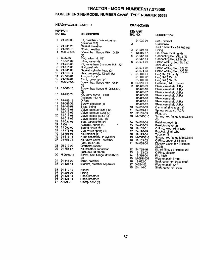
TRACTOR -- MODEL NUMBER 917.273050
KOHLER ENGINE-MODEL NUMBER CV2OS, TYPE NUMBER 65551
HEADNALVE/BREATHER
KEYPARTNO, NO. DESCRIPTION
CRANKCASE
KEYPARTNO. NO. DESCRIPTION
1 24-033-03 Kit, breather cover w/gasket 1 24-032-01(includes 2,3) 2
2 24-041-23 Gasket, breather3 24-096-15 Cover, breather 3 24-294-134 M-0645020 Screw, hex. flange M6xl.0x20 4 12-380-17
(4) 5 24_67-135 X-75-23 Plug, allen hd. 1/8" 24-067-146 12-351-02 Lifter, valve (4) 6 24-874-017 24-755-66 Kit, valve train (Includes 8,11,12)8 24411-05 Rod, push (4) 24-874-029 24-041-08 Gasket, cytinderhead (2) 24-674-0310 24_318-12 Head assembly, #2 cylinder 7 24-108-0111 25-186-01 Arm, rocker (4) 24-108-0212 24-599-01 Pivot, rocker arm (4) 24-108-0313 M-0640034 Screw, hex. flange M6x1.0x34 8 24-018-01
(4) 9 12-422-0914 12-088-16 Screw, hex. flange M10xt .5x90 12-422-13
(8) 12-422-0715 24-755-74 Kit, valve cover - plain 12-422-08
(Includes 16,17) 12-422-1016 24-153-16 O-Ring 12o422-1117 24-086-32 Screw, shoulder (4) 12o422-1218 24-445-01 Strap, lifting 10 24-010-0319 24-016-01 Valve, exhaust (Std.) (2) 11 24-089-21
24-016-02 Valve, exhaust (.25) (2) 12 52-139-0920 24-017-01 Valve, intake (Std.) (2) 13 M-0545010
24-017-02 Valve, intake (.25) (2)21 24-032-05 Seal, valve stem (2) 14 24-018-0422 235011 Retainer, spring(4) 15 24-402-0523 24-089-02 Spring, valve (4) 16 12-153-0124 12-173-01 Cap, valve spring (4) 17 24-126-1925 12-755-03 Kit, retainer (4) 18 12-123-0426 24-318-11 Head assembly,#1 cylinder 19 M-054501627 24-755-76 Kit, valve cover - breather 20 12-15302
(lncl. 16,17,28) 21 24-038-0428 25-313-02 Grommet, rubber29 24-755-57 Kit, breather separator 22 24-755-46
(Includes 28,30-33) 23 12-153-0330 M-0545016 Screw, hex. flange M5x0.8x16 24 12_80-04
(2) 25 M-063100531 24-445-02 Strap, breather 26 12-032-0132 24-126-44 Bracket, breather separator 27 X-25-102
28 24-144-0133 24-112-12 Spacer34 24-294-06 Fitting35 24-326-13 Hose, breather36 24-326-14 Hose, breather37 X-426-9 Clamp, hose (2)
Seal, oil frontCrankcase(USE: Miniblock24 782 05)FittingPin, dowel locating (6)Connecting Rod (Std.) (2)Connecting Rod (.25) (2)Piston w/Ring Set (Std.) (2)(Includes 7,8)Piston w/Ring Set (.25) (2)Piston w(Ring Set (.50) (2)Ring Set (Std.) (2)Ring Set (.25) (2)Ring Set (.50) (2)Retainer, piston pin (4)Shim, camshaft (A.R.)Shim, camsh_'_ (A.R.)Shim, camshaft (A.R.)Shim, camshaft (A.R.)Shim, camshaftShim, camshaft (A.R.)Shim, camshaft (A.R.)Camshaft (Includes 11)Spring, actuating (ACR)Plug, cupScrew, hex. flange M5x0.8xl0(2)Retainer, reed (2)Reed, breather (2)O-Ring, lower oil fill tubeBracket, oil fill tubeTube, oil fillScrew, hex. flange M5x018x16O-Ring, upper oilfill tubeDipstick assembly (Includes22,23)Kit, oil fill cap (thc_udes23)O-Ring, dipstickPin, hitchWasher, plain 6 mmSeal, governor cross shaftWasher, plain 1/4"Shaft, governor cross
57

TRACTOR -- MODEL NUMBER 917.273050
KOHLER ENGINE-MODEL NUMBER CV20S, TYPE NUMBER 65551
CRANKSHAFT I
FUEL SYSTEM]
--1
EXHAUSTJ
2 \/
/1
11
5
\
/g i7 8
\2
9
58

TRACTOR -- MODEL NUMBER 917.273050
KOHLER ENGINE-MODEL NUMBER CV20S, TYPE NUMBER 65551
CRANKSHAFT
KEYPARTNO. NO. DESCRIP_ON
1 24-014-72 Crankshaft (Includes2)2 52-139-09 Plug, cup
EXHAUST
KEYPARTNO. NO. DESCRIPTION
1 244341-02 Gasket, exhaust (`2)2 25.072-04 Stud, M8x1.28x33 (4)
NOT ILLUSTRATED- - 24-522-16 Short Block- - 24-782-05 Miniblock- - 24-755-03 Gasket Set
FUEL SYSTEM
KEYPARTNO. NO. DESCRIPTION
1 24-853-25 Kit, carburetor w/gaskets(Includes 2-4)
2 24-041-15 Gasket, carburetor3 - - Carburetor assembly
(For information only notavailable separately)(Includes 24 757 18, 24-053-25,24-757-'_9, 24-757-20, 24-757-22)
4 24-041-14 Gasket, air cleaner base5 M-0629095 Stud, M6xl.0x95 (2)6 M.0641060 Nut, hex. fiange M6x1.0 (2)7 47-154-01 Clip, cable8 24-353-03 Line, fuel 10-5/8" (2)9 X-426-9 Clamp, hose (6)10 24-086-12 Screw, hex. ca_. M6xl.7x18 (2)11 24-393434 Pump, fuel - pulse12 24-100-01 Nut, plastic (2)13 25-353.03 Line, fuel 13-1/2"14 24-050.02 Fitter, fuel
NOT ILLUSTRATED-- 24-757-18 Kit, overhaul w/gaskets- - 24-757-19 Kit, choke repair w/gaskets
- - 24-757-20- - 24-757-22
Kit, gasketKit, solenoid replacement w/gaskets
59

60

61

62

SUGGESTED GUIDE FOR SIGHTING SLOPES FOR SAFE OPERATION
J "*SIGHTINGGUIDE
ONLY RIDE UP AND DOWN HILL,NOT ACROSS HILL
_1 _ Operate your Tractor up and down the face of slopes (not ]i_| _ greater than 15°), never across the face. Make turns gradu- Ii_| 0 ally to prevent tipping or loss of control. Exercise extreme
:,!!1 caution when changing direction on slopes.

For in-home major brand repair service:Call 24 hours a day, 7 days a week
1-800-4-MY-HOME s" (1-800-469-4663)
Para pedir servicio de reparacibn a domicilio1-800-676-5811
In Canada for all your service and parts needs callAu Canada pour tout le service ou les pieces
1-800-665-4455
For the repair or replacement parts you need:Call 6 am - 11 pm CST, 7 days a week
PartsDirect1-800-366-PART (1-800-366-7278)
Para ordenar piezas con entrega a domicilio1-800-659-7084
For the location of a Sears Parts and Repair Centerin your area:
Call 24 hours a day, 7 days a week1-800-488-1222
For information on purchasing a Sears MaintenanceAgreement or to inquire about an existing Agreement:
Call 9 am - 5 pro, Monday - Saturday1-800-827-6655
167109 Rev. 4 8.23.99 RDiTR/RD Printed in U.S.A.


![2nd term lectures,_cd,_listeria,diphoids[1]](https://img.pdfslide.us/doc/110x75/554b1f82b4c9055d098b534b/2nd-term-lecturescdlisteriadiphoids1.jpg)