Embed Size (px)
Citation preview
Corazón del Bosque
Hydroelectric Scheme
Engineering Design Document
Will Stone
www.aidg.org
Version 1 – May 2010

Abstract
This paper details the design and construction of a Crossflow or Mitchell-Banki hydroelectric turbine
at the public nature park Corazón del Bosque in Guatemala. The turbine is designed for a maximum
output of 2.5kW and is to be used to offset the park’s energy use while also demonstrating the
benefits of micro-hydro systems to the general public in Guatemala.
In addition to documenting the design process for the turbine, the aim of this document is to share
some of the valuable knowledge that AIDG gained through this process. It is hoped that people will
go on to improve on this design and collaborate to improve future installations around the world.
Performance testing of the system will be covered in a future document.
Table of Contents
1 INTRODUCTION ....................................................................................................................................... 5
1.1 CORAZÓN DEL BOSQUE .......................................................................................................................... 5 1.2 XELATECO ............................................................................................................................................. 5 1.3 AIDG ..................................................................................................................................................... 5
2 DESIGN REQUIREMENTS ...................................................................................................................... 5
3 PROJECT SITE ........................................................................................................................................... 6
3.1 HEAD CONDITIONS ................................................................................................................................ 6 3.2 FLOW ..................................................................................................................................................... 7 3.3 POTENTIAL POWER OF WATER RESOURCE ............................................................................................. 8
4 CHOICE OF TURBINE .............................................................................................................................. 8
4.1 KAPLAN TURBINE .................................................................................................................................. 9 4.2 CROSSFLOW (MITCHELL-BANKI) TURBINE .......................................................................................... 11 4.3 THE FINAL CHOICE .............................................................................................................................. 12
5 CONCEPTUAL DESIGN: THE TURBINE RUNNER.......................................................................... 12
5.1 RESEARCH AND LITERATURE REVIEW ................................................................................................. 12 5.2 RUNNER DIAMETER ............................................................................................................................. 13 5.3 NUMBER OF BLADES ............................................................................................................................ 13 5.4 MATERIAL AND CORROSION PROTECTION ........................................................................................... 14 5.5 END PLATES AND BLADE PARTITIONS ................................................................................................. 14 5.6 TURBINE SHAFT ................................................................................................................................... 14 5.7 MODELLING OF TURBINE ..................................................................................................................... 15 5.8 CUTTING COMPONENTS AND ASSEMBLY ............................................................................................. 15
6 CONCEPTUAL DESIGN: NOZZLE AND HOUSING ......................................................................... 17
6.1 NOZZLE SHAPE .................................................................................................................................... 17 6.2 THE NOZZLE IN THREE DIMENSIONS ................................................................................................... 19 6.3 CIRCULAR TO SQUARE TRANSITION ..................................................................................................... 23 6.4 FLOW REGULATION ............................................................................................................................. 25 6.5 DRAUGHT TUBE ................................................................................................................................... 26 6.6 CHANNEL AND EXIT FLOW .................................................................................................................. 26 6.7 NOZZLE MATERIAL AND FRAME .......................................................................................................... 28 6.8 CORROSION PROTECTION ..................................................................................................................... 28
7 DRIVE SYSTEM AND GENERATOR ................................................................................................... 29
7.1 TURBINE BEARINGS ............................................................................................................................. 29 7.2 GENERATOR ......................................................................................................................................... 31
7.2.1 DC Generator ................................................................................................................................. 31 7.2.2 AC Synchronous Generator ............................................................................................................ 31 7.2.3 AC Induction Generator ................................................................................................................. 32
7.3 TRANSMISSION..................................................................................................................................... 32 7.4 FLEXIBLE COUPLING ............................................................................................................................ 33 7.5 MOUNTING AND SHAFT ALIGNMENT ................................................................................................... 34
8 FABRICATION AND LESSONS LEARNT ........................................................................................... 34
8.1 WOBBLE IN TURBINE RUNNER ............................................................................................................. 34 8.2 GALVANISING THE TURBINE RUNNER .................................................................................................. 35 8.3 THE NOZZLE DESIGN ........................................................................................................................... 35 8.4 THE NOZZLE AND TURBINE SEPARATION ............................................................................................ 36

Appendix
Appendix A Technical Specifications
Appendix B References
Appendix C Contact Details
Appendix D Shaft Hub Drawing
Appendix E Turbine Runner Drawing
Appendix F Runner Disc Cutting Template
Appendix G Nozzle Cutting Template
Associated Documentation
Document Description
CDB – Head Loss Calculations.xls Spreadsheet of head loss calculations in penstock Corazón del Bosque Site Survey Report_April 2008_SC.doc
Report on flow conditions at Corazon del Bosque (Spanish)
CDB – Turbine Design Calculations.xls
Spreadsheet of calculations on runner and noozle dimensions and properties
Corazón del Bosque Hydroelectric Scheme AIDG
May 2010 Page 5 of 37
1 Introduction
1.1 Corazón del Bosque
Corazón del Bosque (CDB - www.corazondelbosque.com) is an ecological park on the highway
between Quetzaltenango and Guatemala City in Guatemala. The park has a number of services
including a restaurant, cabins and dormitories, conference centre, Mayan saunas, a nursery and
hiking trails. One of the objectives of the park is to promote environmental awareness and as part of
this objective they have commissioned a micro-hydro system to offset their energy use and to use
for educational purposes.
1.2 XelaTeco
XelaTeco (www.xelateco.com) is a business based in Quetzaltenango, Guatemala that is dedicated to
the manufacture, installation and maintenance of appropriate technologies. Some of the
technologies that XelaTeco works with include hydroelectricity, fuel efficient stoves, biodigeters,
photovoltaic panels and solar water heating. XelaTeco have been contracted by CDB to install the
micro-hydro system at CDB’s park.
1.3 AIDG The Appropriate Infrastructure Development Group (AIDG - www.aidg.org) is an non-governmental
organisation that helps people in developing countries get environmentally sound and affordable
access to energy, sanitation and clean water. This is done through a combination of business
incubation, technological assistance and education. AIDG is responsible for the design of the
Crossflow Turbine that XelaTeco is building and installing at CDB.
2 Design Requirements CDB is currently connected to the electrical network in Guatemala and thus the micro-hydro system
will not be used as a primary source of electricity for the park. The hydroelectricity produced will be
used to offset energy that is used in the park’s office, conference centre and dormitories. Rather
than connect directly to the public grid, the hydroelectricity produced will be provided through a
separate electrical network.
It is expected that the electricity produced will primarily be used to supply energy for lighting,
computers and other simple low energy appliances. A 110-120V, 60Hz system is required to operate
these appliances. A 2.5 kW system is expected to meet their energy requirements.
It is essential that the micro-hydro system is reliable and low maintenance. For this reason, the
system should be designed to be as simple as possible.
The turbine is to be located in a machine room to be built by CDB. This room will protect the turbine
in flood conditions and will also keep the system components secure from theft.

Corazón del Bosque Hydroelectric Scheme AIDG
May 2010 Page 6 of 37
3 Project Site The micro-hydro system is to utilise the power of a small creek that flows through the park. There is
an existing small weir (2.5m high) that is located approximately 100m from the park office,
conference area and salon.
CDB have constructed a small machine room (4m x 4m) to house the turbine and other system
components. This room is approximately 5m from the weir.
Figure 1 – Corazón del Bosque site (machine room on left and weir on right)
3.1 Head Conditions
Measurements were performed on the gross head available at the site using a water filled tube and
tape measure. The measurements are shown in Figure 2 below. XelaTeco plan on extending the weir
height by one metre to raise the water level of the damn and provide more energy.
The centre of the turbine will be positioned 650mm above the average river level. This will give
sufficient clearance for the water to exit the turbine, even when the river level is high. With the
turbine located at this level, and without using a draught tube (see section 6.5) the gross head at the
centre of the turbine is estimated to be 2.86m (see Figure 2).

Corazón del Bosque Hydroelectric Scheme AIDG
May 2010 Page 7 of 37
Figure 2 – Head Measurements
XelaTeco plan on using two 8” diameter tubes to supply water to the turbine from the weir. The
pipes will be approximately 8m in length and will incorporate 3 sharp 45 degree bends in each tube.
Due to frictional head losses in the tubes and bends, the net head of the water flowing into the
turbine will be lower than the gross head. There will also be losses in the nozzle of the turbine
depending on its design.
The expected head losses are calculated using the spreadsheet “CB - Head Loss Calcs.xls” based on
the expected penstock configuration. The results of these calculations for various flows are shown in
Table 1. For the maximum flow conditions, the total head losses in the tubes will be significant.
Flow (L/s) 250 150 50
Gross Head (m) 2.86 2.86 2.86
Major Pipe Loss (m) 0.39 0.15 0.02
Minor Losses (m) 0.79 0.30 0.04
Total Head Loss (m) 1.18 0.45 0.06
Net Head (m) 1.68 2.4 2.80
Table 1 – System Head Losses
Because of changes in net head, the optimum speed of the turbine is expected to change slightly for
the different flows.
3.2 Flow
A feasibility study on the site was performed and a report produced by XelaTeco in April, 2008. The
document is named “Corazon del Bosque Site Survey Report.doc” and is written in Spanish.

Corazón del Bosque Hydroelectric Scheme AIDG
May 2010 Page 8 of 37
To estimate the flows at the site, flow measurements were performed using the “Salt Gulp Method”
and the results were correlated with long-term rainfall data for the river catchment area. The report
estimates the maximum flow to be 360L/s in September and the minimum flow to be 100L/s in June
and July. The results are summarised in Table 2 below.
Month Estimated Flow
January 220
February 180
March 180
April 160
May 160
June 100
July 100
August 110
September 360
October 350
November 310
December 270
Table 2 – Estimated river flow at Corazón del Bosque
3.3 Potential Power of Water Resource
The gross power (P) of the water available at CDB can be calculated using the following formula:
QghP ρ=
Where: ρ is the density of water (1000kg/m^3)
Q is the flow in m^3/s
h is the head in m
Taking into account the expected head losses in the system, as discussed in Section 3.1, the net head
at the turbine is expected to be 1.7m without draught tube. Substituting this into the above
equation with the expected maximum flow of 0.25 m^3/s, the maximum power available is P = 4.2
kW.
4 Choice of Turbine The selection of the best turbine for a particular site is dependent on site conditions (head and flow),
the desired speed of the turbine and whether the turbine is expected to operate under part-flow
conditions.
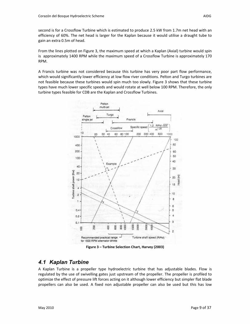
Figure 3 below is a plot from Harvey (1993) that is used to select the relevant turbine for different
site conditions (see Fig 5.1.2 page 155). To use this figure, a straight line is plotted from the expected
turbine power (taking into account estimated efficiency) to the site head. A second line is then
drawn perpendicular to the first line to see which turbine types are suitable for different rotational
speeds.
Two sets of lines have been plotted on Figure 3 for the CDB site conditions. The first is for a Kaplan
turbine which is estimated to produce 4.3 kW from 2.2 m net head with an efficiency of 80%. The
Corazón del Bosque Hydroelectric Scheme AIDG
May 2010 Page 9 of 37
second is for a Crossflow Turbine which is estimated to produce 2.5 kW from 1.7m net head with an
efficiency of 60%. The net head is larger for the Kaplan because it would utilise a draught tube to
gain an extra 0.5m of head.
From the lines plotted on Figure 3, the maximum speed at which a Kaplan (Axial) turbine would spin
is approximately 1400 RPM while the maximum speed of a Crossflow Turbine is approximately 170
RPM.
A Francis turbine was not considered because this turbine has very poor part flow performance,
which would significantly lower efficiency at low flow river conditions. Pelton and Turgo turbines are
not feasible because these turbines would spin much too slowly. Figure 3 shows that these turbine
types have much lower specific speeds and would rotate at well below 100 RPM. Therefore, the only
turbine types feasible for CDB are the Kaplan and Crossflow Turbines.
Figure 3 – Turbine Selection Chart, Harvey (2003)
4.1 Kaplan Turbine
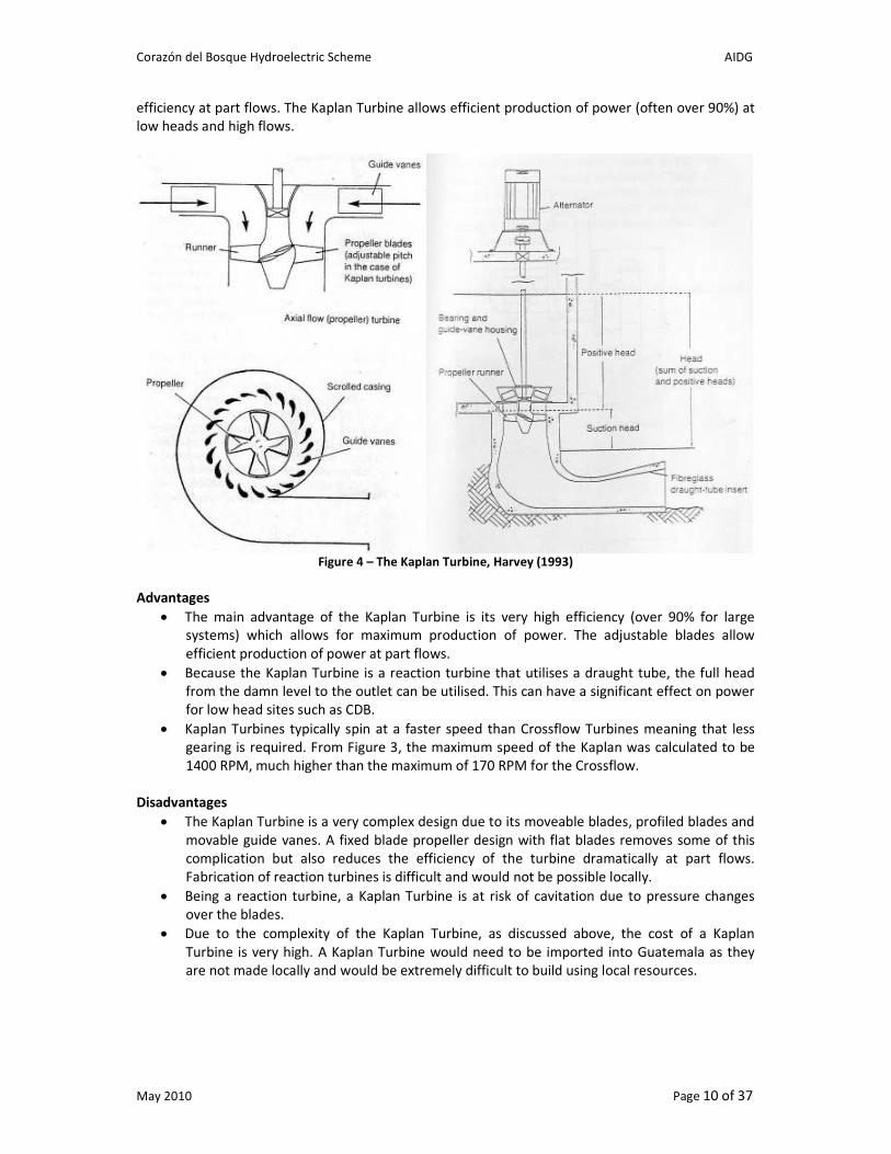
A Kaplan Turbine is a propeller type hydroelectric turbine that has adjustable blades. Flow is
regulated by the use of swivelling gates just upstream of the propeller. The propeller is profiled to
optimize the effect of pressure lift forces acting on it although lower efficiency but simpler flat blade
propellers can also be used. A fixed non adjustable propeller can also be used but this has low
Corazón del Bosque Hydroelectric Scheme AIDG
May 2010 Page 10 of 37
efficiency at part flows. The Kaplan Turbine allows efficient production of power (often over 90%) at
low heads and high flows.
Figure 4 – The Kaplan Turbine, Harvey (1993)
Advantages
• The main advantage of the Kaplan Turbine is its very high efficiency (over 90% for large
systems) which allows for maximum production of power. The adjustable blades allow
efficient production of power at part flows.
• Because the Kaplan Turbine is a reaction turbine that utilises a draught tube, the full head
from the damn level to the outlet can be utilised. This can have a significant effect on power
for low head sites such as CDB.
• Kaplan Turbines typically spin at a faster speed than Crossflow Turbines meaning that less
gearing is required. From Figure 3, the maximum speed of the Kaplan was calculated to be
1400 RPM, much higher than the maximum of 170 RPM for the Crossflow.
Disadvantages
• The Kaplan Turbine is a very complex design due to its moveable blades, profiled blades and
movable guide vanes. A fixed blade propeller design with flat blades removes some of this
complication but also reduces the efficiency of the turbine dramatically at part flows.
Fabrication of reaction turbines is difficult and would not be possible locally.
• Being a reaction turbine, a Kaplan Turbine is at risk of cavitation due to pressure changes
over the blades.
• Due to the complexity of the Kaplan Turbine, as discussed above, the cost of a Kaplan
Turbine is very high. A Kaplan Turbine would need to be imported into Guatemala as they
are not made locally and would be extremely difficult to build using local resources.

Corazón del Bosque Hydroelectric Scheme AIDG
May 2010 Page 11 of 37
4.2 Crossflow (Mitchell-Banki) Turbine A Crossflow or Mitchell-Banki Turbine is a type of impulse turbine where the water enters the
turbine transversely or across the turbine blades. The turbine consists of a cylindrical water wheel
with a horizontal shaft and numerous curved blades. The water passes through the turbine blades
twice, once on entry and once on exit. A locally made Crossflow Turbine typically has an efficiency
from 60% to 75% while large sophisticated machines may have efficiencies as high as 85%.
Crossflow Turbines are relatively simple turbines and can be manufactured easily in developing
countries.
Figure 5 – The Ossberger Turbine (www.ossberger.de)
Advantages
• The Crossflow Turbine is a simple design. The runner blades can be made by cutting pipe
lengthwise into strips and welding them between metal discs. Due to its simplicity it is also
easy to maintain.
• The efficiency of the Crossflow Turbine remains relatively high for different flow and
different load conditions.
• The turbine is able to withstand a large amount of debris and rubbish in the water and also is
self-cleaning. This also makes it easier to maintain and more reliable as it doesn’t get
clogged with debris.
Disadvantages
• The efficiency of the Crossflow Turbine is typically lower than other turbines
• The speed of the Crossflow Turbine is lower than reaction turbines. From Figure 3, the
maximum speed was calculated to be 170 RPM meaning that a gearbox would be required
to drive a generator. This gearbox would further reduce the efficiency of the system.

Corazón del Bosque Hydroelectric Scheme AIDG
May 2010 Page 12 of 37
4.3 The Final Choice The turbine design selected for the CDB site is the Crossflow Turbine. Reasons for this design being
selected are:
• The system will be less expensive.
• A Crossflow Turbine will operate more reliably at CDB, especially with the large amount of
rubbish that enters the creek at this site.
• The CDB turbine is to be a demonstration project and the park is already connected to the
main grid. It is more important that the turbine be a reliable system to demonstrate the
benefits of hydroelectricity to the public. It is less important that every watt of energy is
extracted from the site using a higher efficiency turbine.
• A Crossflow Turbine can be fabricated in Guatemala from local materials. This reduces the
reliance on imported components and will also make maintenance of the system faster and
easier.
• The extra costs in gearing due to the lower speed of the Crossflow Turbine will be more than
compensated for by the lower cost of this type of turbine. As discussed above, the lower
efficiency due to more gearing is less of a concern for this demonstration project.
5 Conceptual Design: The Turbine Runner The reasoning for the different design attributes of the turbine runner are discussed in the following
section. A summary of the turbine dimensions and characteristics is given in Appendix A.
5.1 Research and Literature Review
All reference material that was collected for the design of the CDB micro-hydro system is listed in
the table in Appendix B. Most of the electronic documents are also available on www.aidg.net.
The most useful references for designing the runner were Harvey (1993), Mockmore and Merryfield
(1949) and Marchegiani. The Walsh Hydro Construction Guide was also used to verify the blade
dimensions that were calculated using Mockmore and Merryfield´s complicated document. The
equations from these sources were entered into the spreadsheet: “CDB – Turbine Design
Calculations.xls”. The calculations from each source are given on a separate sheet within the
spreadsheet.
Although the complexity and level of detail from each source varied, the calculations generally gave
consistent results for the runner dimensions and operating parameters. The runner diameter and
speed were especially consistent for each set of calculations based on a net head of 1.7 m.
The length of the runner is dependent on the thickness of the nozzle exit and each source had a
slightly different approach on the nozzle design. Mockmore and Merryfield only considered a thin
nozzle that hits one blade at a time (Jet Thickness Factor of 0.095). This results in a very long runner
(1.4 m) and this nozzle design is generally considered to be less efficient than a spiral design of
Marchegiani that was chosen for the CDB turbine (see Section 6.1). When the Jet Thickness Factor is
increased to 0.17, the runner length calculated from both ITDG and Mockmore and Merryfield
matches that from Marchegiani´s spiral nozzle and gives a length of 810 mm.
The blade dimensions for the runner are only considered by Mockmore and Merryfield and
Marchegiani (the Walsh Hydro dimensions are a simplified version of Mockmore and Merryfield´s
equations). Mockmore and Merryfield´s blades are only dependent on runner diameter while
Marchegiani´s blades are dependent on diameter and number of blades. However, the entry and

Corazón del Bosque Hydroelectric Scheme AIDG
May 2010 Page 13 of 37
exit angle of the blades are always the same for all sources and the dimensions match when 27
blades are used with Marchegiani´s dimensions. Mockmore and Merryfield´s blade dimensions were
used for the CDB turbine as the diameter of the blades calculated matched the diameter of pipe
sections that could be purchased in Guatemala.
5.2 Runner Diameter
In his manual on small Crossflow Turbine construction, Breslin (1980) states that for small turbines,
the runner diameter ranges from 200 to 500 mm. He writes that some of the factors that need to be
considered when selecting the runner diameter are:
• Reducing the diameter usually results in reduced hydrodynamic performance.
• Increasing the diameter of the runner reduces its operating speed. This means that more
gearing is required which can increase losses and expenses.
• Ease of manufacture needs to be considered with larger turbines usually being easier to
construct at a higher level of quality.
The diameter chosen for the CDB turbine is 316 mm. Using Mockmore and Merryfield´s blade
dimensions, this diameter results in a blade diameter of 104 mm or 4”, which is a standard metal
pipe size in Guatemala.
A relatively small runner diameter was chosen at the lower end of the 200 to 500 mm range so that
the turbine would spin faster (163 rpm) than a larger turbine (it would have spun at 100 rpm with a
500mm runner). However, it was decided to not go any smaller than 316mm as it would have
become more difficult to fabricate and hydrodynamic performance probably would have decreased.
5.3 Number of Blades
In all the literature on Crossflow Turbines, there are differing opinions on the optimum number of
blades. Generally, however, most references state that more blades are better and that it is a trade
off between a more efficient turbine with a higher number of blades and ease of manufacture with
turbines with less blades being much easier to weld.
Mockmore and Merryfield (1949) state that the optimum number of blades can only be found by
experiment. They state that fewer blades may cause pulsating power while a larger number of
blades may cause excessive friction loss.
Marchegiani performs a review on the number of blades from different sources of literature and
finds that the optimum is between 24 and 30. Some of the highly efficient commercial turbines (such
as the Ossberger) have as many as 37 blades but these are generally designed for higher head sites.
Experimental studies have been performed to try and find optimum number of blades. Azim and
Desai found that the efficiency of their test turbine increased as the number of blades was increased
(efficiency increased as much as 15% when number of blades was increased from 15 to 25).
However, this test was only performed under one set of head conditions.
For the CDB turbine, it was decided to incorporate as many blades as possible while ensuring that
the blades could still be welded without major difficulties. Scale templates were printed out for the
chosen runner diameter of 316 mm with each template having a different number of blades. These
were taken to the XelaTeco workshop and the welders there considered the weldability for the
different templates. It was decided that a maximum of 20 blades could be used for this turbine size.

Corazón del Bosque Hydroelectric Scheme AIDG
May 2010 Page 14 of 37
5.4 Material and Corrosion Protection Because hydroelectric turbines are continuously exposed to water, it is important that they have a
high level of corrosion protection. It would not be acceptable to build the turbine from mild steel
with no form of protection.
In the Walsh Hydro Construction Guide it is written that the company was originally using stainless
steel to construct their turbines. However, the turbines were failing due to the lower durability of
stainless steel. Stones were chipping away at the ends of the blades and triggering creep fatigue.
Walsh Hydro now uses mild steel which is then galvanised after construction.
Another option that was considered for the CDB turbine was painting the turbine after construction.
However, painting the inside of the turbine would have been very difficult and the paint would not
have provided a durable form of corrosion protection.
The workshop “Grupo ITM” was found in Guatemala that performs both electroplating
(Q3.75/pound) and hot-dip galvanising (Q16/pound). See Appendix C for contact details. The
electroplating was selected as a form of corrosion protection for the turbine as this was believed to
provide the smoothest surface finish and reduce losses. The hot-dip galvanising that was performed
on the nozzle, however, was found to be as smooth as or smoother than the electroplating.
Although it is a higher cost, hot-dip galvanising may be a better option for future turbines as it
provides a thicker layer of protective zinc (see Section 8.2 on lessons learnt).
5.5 End Plates and Blade Partitions
The turbine is designed for a maximum flow of 250 L/s. For this flow and Marchegiani´s nozzle
design, the length of the turbine is calculated as 810mm. Because these blades are reasonably long,
there is a risk that the blades will flex and lead to failure at the junction of blade and disc.
Approximate calculations were performed to determine the stress within the blades due to the force
of the water. It was found that deflection could potentially occur at the centre of the blades and thus
it was decided to include a partition disc near the middle of the turbine. This disc is placed at 40% of
the distance along the turbine rather than the middle because the nozzle is partitioned at 40% of the
turbine length (see Section 6.4). Therefore, there is likely to be less interference to the flow at this
point in the turbine because the flow is already being interrupted by the nozzle partition.
The thickness of the end plates was chosen as ¼” (6mm) as the plates will be less susceptible to
warping when they are being welded. If thicker plates were used, they would become much harder
to cut using the plasma cutter and would significantly increase the weight of the turbine. Due to the
extra thickness of the plates, the length of the turbine blades were increased to 828mm from
810mm to take into account the extra 3 x 6 = 18mm.
5.6 Turbine Shaft
The shaft of the turbine is 1” (25.4 mm) in diameter and is sized in accordance with the shaft sizing
chapter in the Micro Hydro Design Manual, Harvey (1993).
Two options were considered for the turbine shaft design. One was to have a single shaft that passes
through the entire turbine. The second option was two separate shafts that are bolted onto the end
plates. The advantage of the second option is that there would be no interference to the flow
passing through the centre of the turbine.
Corazón del Bosque Hydroelectric Scheme AIDG
May 2010 Page 15 of 37
The second option above was selected in the hope of improving the efficiency of the turbine. Hubs
were designed with eight 3/8” bolts to connect the hubs to the end plates. A drawing of the hub that
was manufactured by Tornos Gutierrez is shown in Appendix D. This option was later found to cause
many problems (see Section 8.1) and the first single shaft option is recommended for future designs.
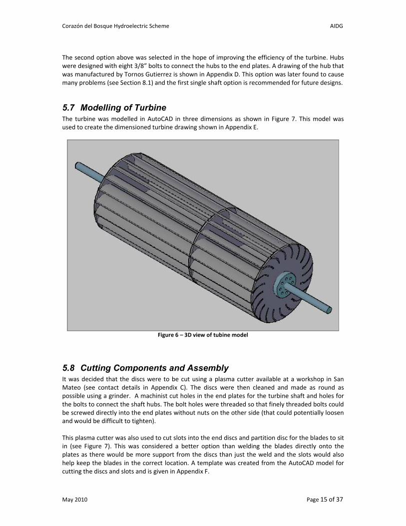
5.7 Modelling of Turbine
The turbine was modelled in AutoCAD in three dimensions as shown in Figure 7. This model was
used to create the dimensioned turbine drawing shown in Appendix E.
Figure 6 – 3D view of tubine model
5.8 Cutting Components and Assembly
It was decided that the discs were to be cut using a plasma cutter available at a workshop in San
Mateo (see contact details in Appendix C). The discs were then cleaned and made as round as
possible using a grinder. A machinist cut holes in the end plates for the turbine shaft and holes for
the bolts to connect the shaft hubs. The bolt holes were threaded so that finely threaded bolts could
be screwed directly into the end plates without nuts on the other side (that could potentially loosen
and would be difficult to tighten).
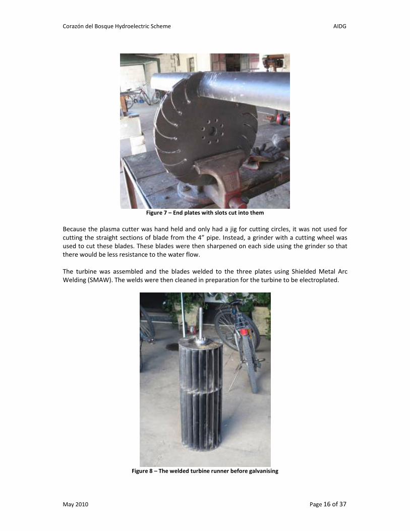
This plasma cutter was also used to cut slots into the end discs and partition disc for the blades to sit
in (see Figure 7). This was considered a better option than welding the blades directly onto the
plates as there would be more support from the discs than just the weld and the slots would also
help keep the blades in the correct location. A template was created from the AutoCAD model for
cutting the discs and slots and is given in Appendix F.
Corazón del Bosque Hydroelectric Scheme AIDG
May 2010 Page 16 of 37
Figure 7 – End plates with slots cut into them
Because the plasma cutter was hand held and only had a jig for cutting circles, it was not used for
cutting the straight sections of blade from the 4” pipe. Instead, a grinder with a cutting wheel was
used to cut these blades. These blades were then sharpened on each side using the grinder so that
there would be less resistance to the water flow.
The turbine was assembled and the blades welded to the three plates using Shielded Metal Arc
Welding (SMAW). The welds were then cleaned in preparation for the turbine to be electroplated.
Figure 8 – The welded turbine runner before galvanising

Corazón del Bosque Hydroelectric Scheme AIDG
May 2010 Page 17 of 37
6 Conceptual Design: Nozzle and Housing The nozzle is a critical part of the system design and together with the turbine, determines the
efficiency of the system. Losses must be as small as possible and the flow must be uniform through
the nozzle to achieve the highest possible transformation of potential energy to kinetic energy. This
is particularly relevant for the CDB turbine as head losses are already significant (see Section 3.1) and
any further losses would have a significant effect on performance.
6.1 Nozzle Shape A number of different nozzle designs are shown in the literature. Figure 9 through to Figure 11 show
some of these different designs. Some of the nozzles utilise moveable bottom plates to regulate flow
while others are simpler with no plate. However, the top plates of all nozzles seem to have a
rounded spiral shape to smoothly introduce the flow into the turbine.
One of the largest variations in the nozzle design is the nozzle entry arc which is the angle over which
the water enters the turbine. For example, a nozzle with an entry arc of 90 degrees has the water
entering a quarter of the turbine’s blades at the same time.
Banki’s calculations translated in Mockmore and Merryfield’s paper are based on a narrow jet of
water that only hits one turbine blade at a time. However, the design of the Crossflow Turbine
seems to have evolved to have a larger nozzle where the water jet hits multiple blades at a time. A
literature review performed by Marchegiani has shown that the nozzle entry arc varies from 30-120
degrees for different designs. However, he states that most of the literature seems to agree that this
angle should be around 90 degrees.
Figure 9 – Nozzle Diagrams from Azim, Barglazan (2005) and Mockmore and Merryfield (1949)

Corazón del Bosque Hydroelectric Scheme AIDG
May 2010 Page 18 of 37
Figure 10 – Nozzle diagrams from Mockmore and Merryfield (1949), Breslin (1980) and Meier
Figure 11 – Nozzle of the SKAT turbine (www.entec.ch)
Although there are many diagrams of different nozzle shapes and designs shown in the literature,
there are no specific dimensions given except for Marchegiani who gives a mathematical equation to
describe a smooth spiral transition. This equation is used in the spreadsheet “CDB – Turbine Design
Calculations.xls” to plot the shape of the top nozzle plate for the turbine dimensions discussed in
Section 5. Four blades were selected to be in the entry of the nozzle which resulted in a nozzle entry
arc of 77 degrees. The spreadsheet gives the nozzle shape in Cartesian coordinates which were then
plotted in AutoCAD to model the nozzle (see Figure 12).
In the vertical plane, the top and bottom nozzle plates constantly expand at an angle of 5 degrees
(10 degrees in total). This is the angle given in the nozzle design by Marchegiani for the bottom
nozzle plate which meets the runner. The total expansion rate of 10 degrees gives a smooth gradual
transition.
The literature shows that both vertical and horizontal nozzle orientations are commonly used for
Crossflow Turbines. Because the penstock tubes at CDB enter horizontally into the machine room, a
horizontal nozzle orientation is the logical choice for the turbine.

Corazón del Bosque Hydroelectric Scheme AIDG
May 2010 Page 19 of 37
Figure 12 - Side View of Nozzle and turbine runner
6.2 The Nozzle in Three Dimensions The exit of the nozzle for the CDB Crossflow Turbine is thin and rectangular whereas the water
enters the nozzle from two round 8” PVC pipes. Therefore a dramatic change is cross-sectional shape
is required. From entry to exit, the nozzle needs to increase in width in the horizontal plane and
decrease in width in the vertical plane.
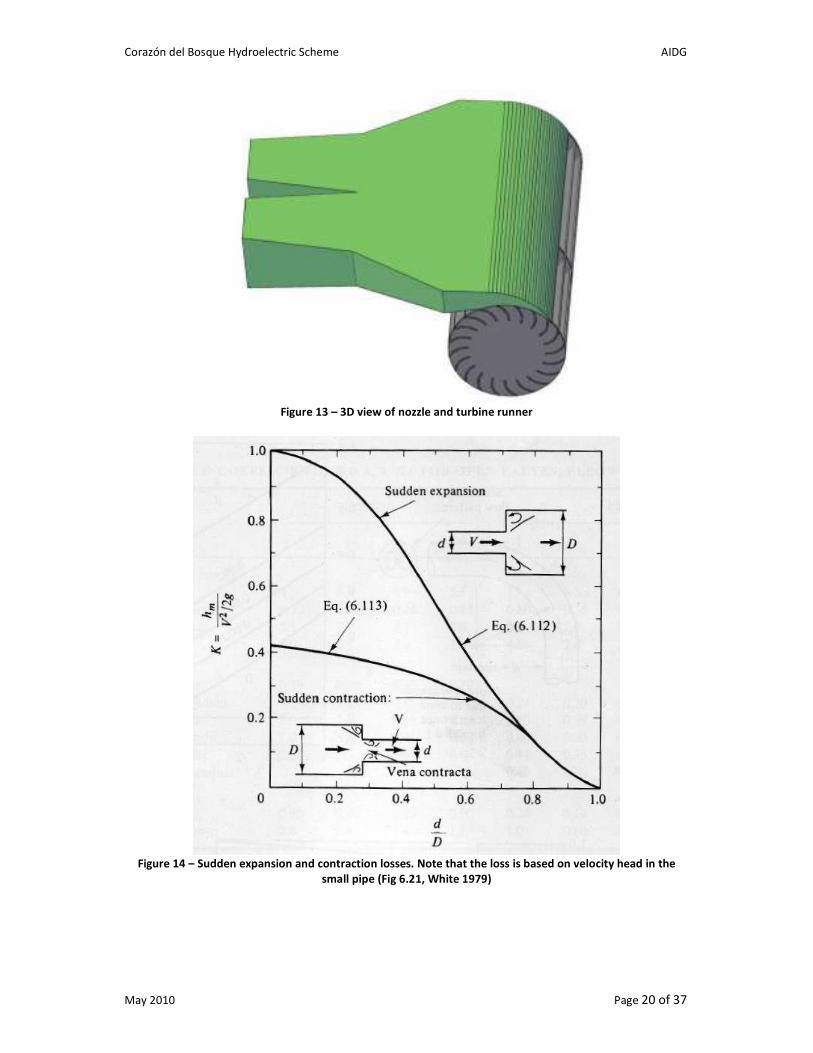
A 3D representation of the CDB nozzle is shown in Figure 13. One of the main influences on the
nozzle shape was the necessity to keep the cross sectional area of the nozzle constant and prevent
any expansion in the flow. As described on pages 336-338 of White (1979), any expansion in a flow
results in large head losses. This is shown in Figure 14 which shows sudden expansions and Figure 15
which shows gradual expansions. At an exit the flow loses its entire velocity head and therefore a
sudden expansion can have a minor loss factor (K) as large as 1.0. For gradual expansions, the loss
factor can actually exceed 1.0 due to gross flow separation. With the CDB turbine which has a
maximum flow of 250 L/s, a minor loss factor of 1.0 would result in extra head losses of 0.8m, 30% of
the gross head - clearly unacceptable.
Corazón del Bosque Hydroelectric Scheme AIDG
May 2010 Page 20 of 37
Figure 13 – 3D view of nozzle and turbine runner
Figure 14 – Sudden expansion and contraction losses. Note that the loss is based on velocity head in the
small pipe (Fig 6.21, White 1979)
Corazón del Bosque Hydroelectric Scheme AIDG
May 2010 Page 21 of 37
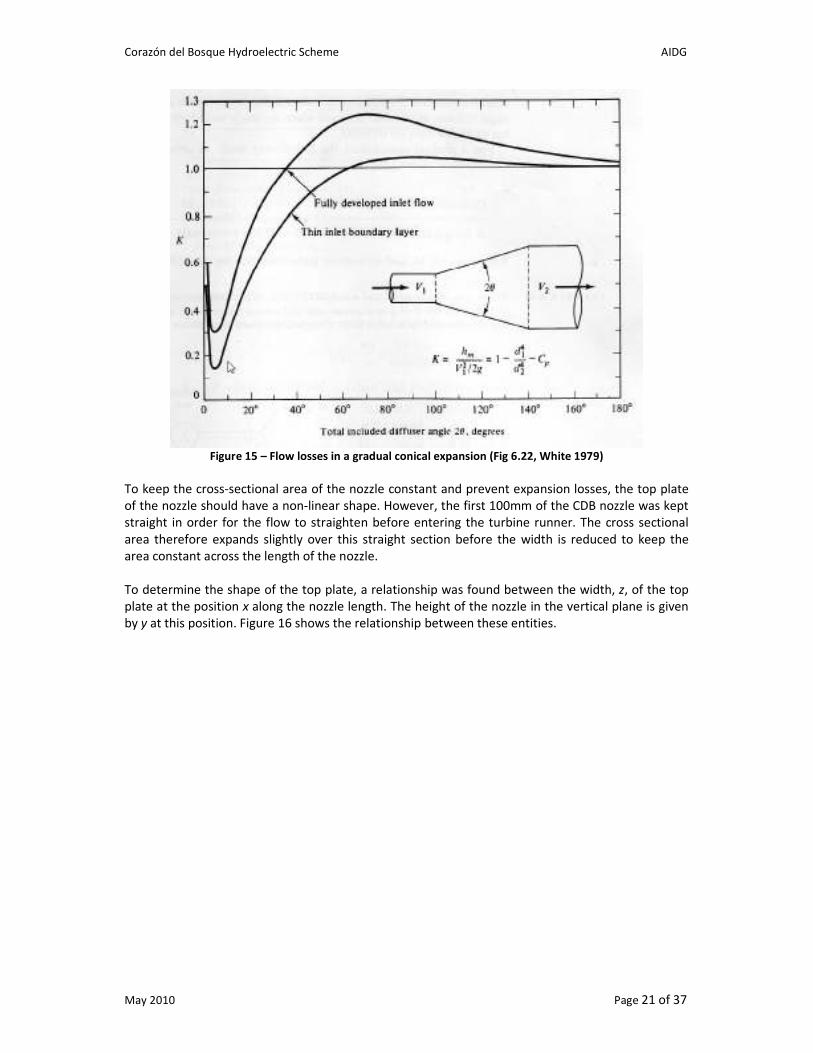
Figure 15 – Flow losses in a gradual conical expansion (Fig 6.22, White 1979)
To keep the cross-sectional area of the nozzle constant and prevent expansion losses, the top plate
of the nozzle should have a non-linear shape. However, the first 100mm of the CDB nozzle was kept
straight in order for the flow to straighten before entering the turbine runner. The cross sectional
area therefore expands slightly over this straight section before the width is reduced to keep the
area constant across the length of the nozzle.
To determine the shape of the top plate, a relationship was found between the width, z, of the top
plate at the position x along the nozzle length. The height of the nozzle in the vertical plane is given
by y at this position. Figure 16 shows the relationship between these entities.
Corazón del Bosque Hydroelectric Scheme AIDG
May 2010 Page 22 of 37
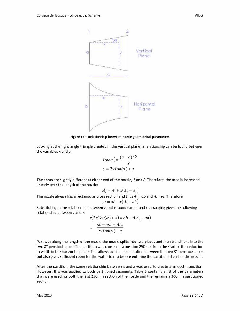
Figure 16 – Relationship between nozzle geometrical parameters
Looking at the right angle triangle created in the vertical plane, a relationship can be found between
the variables x and y:
( )
axTany
x
ayTan
+=
−=
)(2
2/)(
α
α
The areas are slightly different at either end of the nozzle, 1 and 2. Therefore, the area is increased
linearly over the length of the nozzle:
( )121 AAxAAx −+=
The nozzle always has a rectangular cross section and thus A1 = ab and Ax = yz. Therefore
( )abAxabyz −+= 2
Substituting in the relationship between x and y found earlier and rearranging gives the following
relationship between z and x:
( ) ( )
azxTan
xAabxabz
abAxabaxTanz
+
+−=
−+=+
)(
)(2
2
2
α
α
Part way along the length of the nozzle the nozzle splits into two pieces and then transitions into the
two 8” penstock pipes. The partition was chosen at a position 250mm from the start of the reduction
in width in the horizontal plane. This allows sufficient separation between the two 8” penstock pipes
but also gives sufficient room for the water to mix before entering the partitioned part of the nozzle.
After the partition, the same relationship between x and z was used to create a smooth transition.
However, this was applied to both partitioned segments. Table 3 contains a list of the parameters
that were used for both the first 250mm section of the nozzle and the remaining 300mm partitioned
section.

Corazón del Bosque Hydroelectric Scheme AIDG
May 2010 Page 23 of 37
Table 3 – Parameters for calculating nozzle shape
The relationship between x and z was calculated in excel and plotted in AutoCAD to give the
optimum nozzle shape. This shape is shown by the red line in Figure 17. Rather than use this curved
shape, the optimum shape is approximated by two straight lines (green lines in Figure 17) to simplify
construction of the nozzle. This cross sectional area using these straight lines only deviates by a
maximum of 6% from the optimum.
Figure 17 – Top View of Nozzle
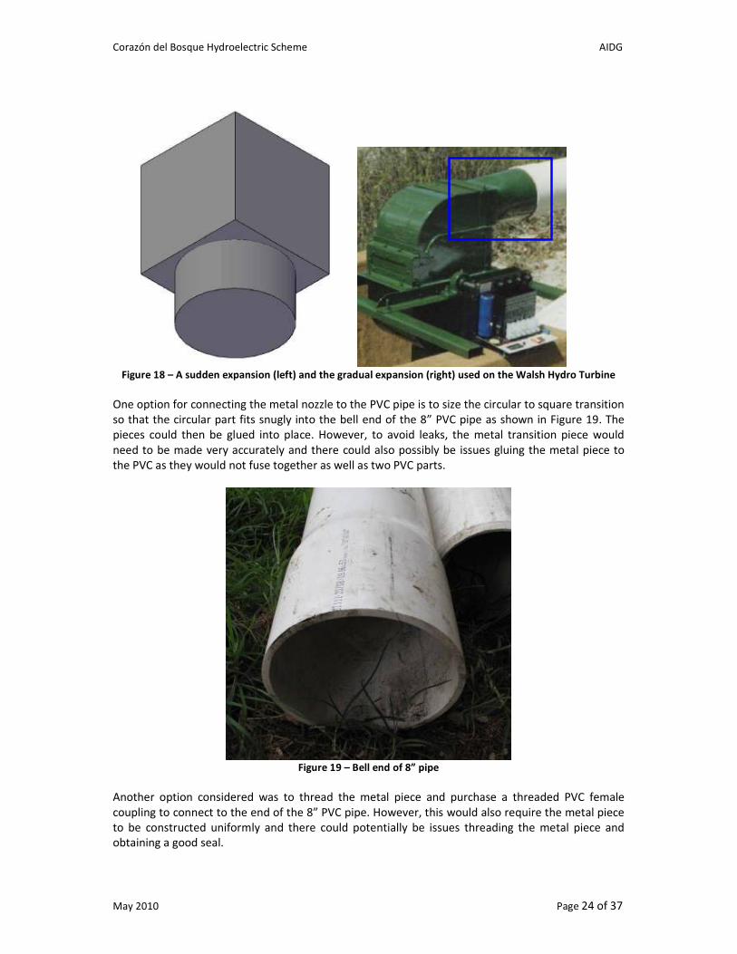
6.3 Circular to Square Transition
At the entry of the nozzle, the two square parts of the nozzle need to transition to the circular shape
of the two 8” penstock pipes. The simplest way to do this would be to have the circular pipes enter
into a square end of the nozzle as shown in the left picture in Figure 18. However, this would result
in a sudden expansion and as discussed in Section 6.2, this would result in significant losses. To
prevent this, a transition piece is used that is a metal cylinder that is squeezed on the other end to
form a square. An example of this is highlighted in the right picture of Figure 18 which shows a
circular to square transition on the Walsh Hydro Crossflow Turbine.
Parameter Values (before partition) Values (after partition)
α 5 degrees 5 degrees
a 75.8mm 119.5mm
b 828mm 255.7mm
c 250mm 299.8mm
Corazón del Bosque Hydroelectric Scheme AIDG
May 2010 Page 24 of 37
Figure 18 – A sudden expansion (left) and the gradual expansion (right) used on the Walsh Hydro Turbine
One option for connecting the metal nozzle to the PVC pipe is to size the circular to square transition
so that the circular part fits snugly into the bell end of the 8” PVC pipe as shown in Figure 19. The
pieces could then be glued into place. However, to avoid leaks, the metal transition piece would
need to be made very accurately and there could also possibly be issues gluing the metal piece to
the PVC as they would not fuse together as well as two PVC parts.
Figure 19 – Bell end of 8” pipe
Another option considered was to thread the metal piece and purchase a threaded PVC female
coupling to connect to the end of the 8” PVC pipe. However, this would also require the metal piece
to be constructed uniformly and there could potentially be issues threading the metal piece and
obtaining a good seal.
Corazón del Bosque Hydroelectric Scheme AIDG
May 2010 Page 25 of 37
The final option, which was adopted for the CDB turbine, was to use flanges to connect the metal
transition piece and PVC pipe. PVC flanges were purchased for the 8” pipe and metal flanges were
fabricated from ¼” sheet steel to connect to the PVC flanges. Simple rubber gaskets were made to fit
between the metal and PVC flanges. These flanges allow a good seal and have the additional benefit
of allowing the nozzle to be disconnected from the PVC pipes. See Appendix A for technical
information on the flanges used.
6.4 Flow Regulation Crossflow Turbines have good efficiency at part flow which is one of the reasons that this type of
turbine was selected for CDB (see Section 4). However, to use the turbine at part flow, some form of
flow regulation is required.
One way to control the flow to a Crossflow Turbine is to use a flap or profile shaped semicircular
segment as shown earlier in Figure 11. The flap can be controlled hydraulically or by a threaded bolt
with thumbscrew on either side of the nozzle.
Another option for controlling flow is to block off part of the turbine with vertical partitions so that
the water is only flowing over part of the turbine. This does not allow as fine an adjustment of flow
as the above option, but is easier to fabricate. For this reason, this option was selected for the
turbine at CDB.
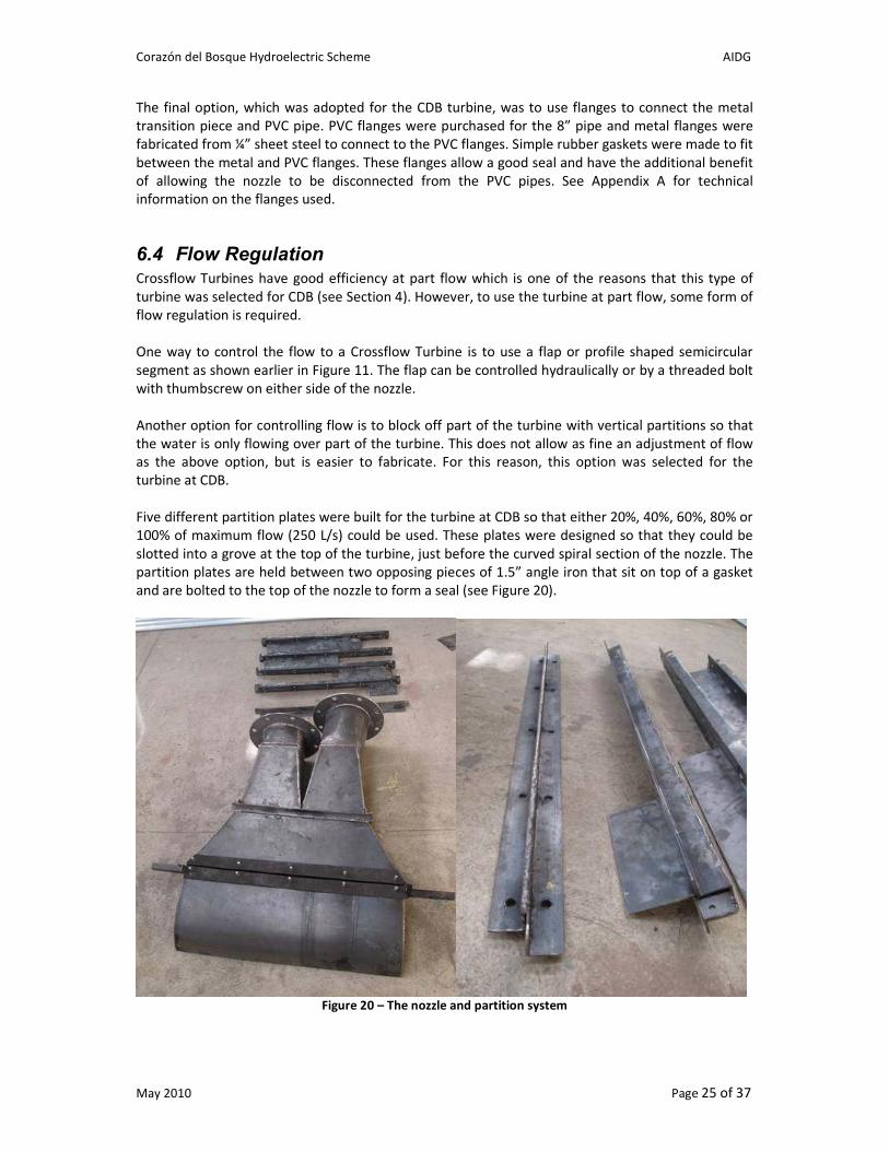
Five different partition plates were built for the turbine at CDB so that either 20%, 40%, 60%, 80% or
100% of maximum flow (250 L/s) could be used. These plates were designed so that they could be
slotted into a grove at the top of the turbine, just before the curved spiral section of the nozzle. The
partition plates are held between two opposing pieces of 1.5” angle iron that sit on top of a gasket
and are bolted to the top of the nozzle to form a seal (see Figure 20).
Figure 20 – The nozzle and partition system
Corazón del Bosque Hydroelectric Scheme AIDG
May 2010 Page 26 of 37
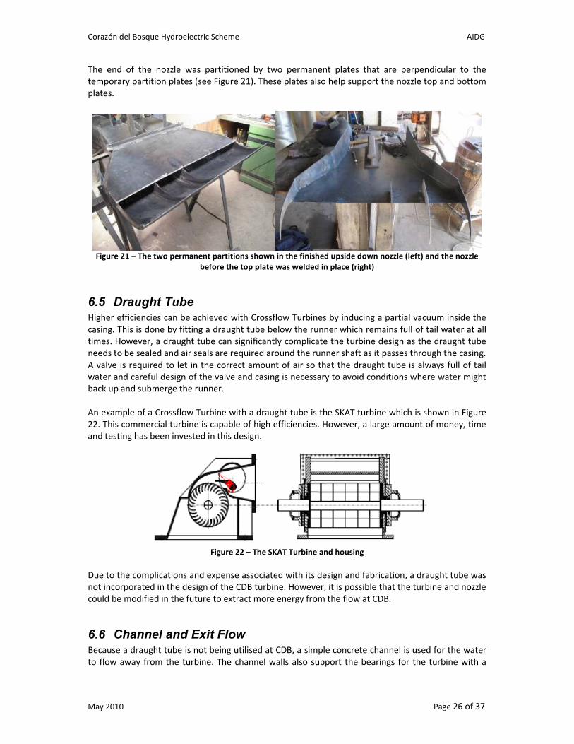
The end of the nozzle was partitioned by two permanent plates that are perpendicular to the
temporary partition plates (see Figure 21). These plates also help support the nozzle top and bottom
plates.
Figure 21 – The two permanent partitions shown in the finished upside down nozzle (left) and the nozzle
before the top plate was welded in place (right)
6.5 Draught Tube Higher efficiencies can be achieved with Crossflow Turbines by inducing a partial vacuum inside the
casing. This is done by fitting a draught tube below the runner which remains full of tail water at all
times. However, a draught tube can significantly complicate the turbine design as the draught tube
needs to be sealed and air seals are required around the runner shaft as it passes through the casing.
A valve is required to let in the correct amount of air so that the draught tube is always full of tail
water and careful design of the valve and casing is necessary to avoid conditions where water might
back up and submerge the runner.
An example of a Crossflow Turbine with a draught tube is the SKAT turbine which is shown in Figure
22. This commercial turbine is capable of high efficiencies. However, a large amount of money, time
and testing has been invested in this design.
Figure 22 – The SKAT Turbine and housing
Due to the complications and expense associated with its design and fabrication, a draught tube was
not incorporated in the design of the CDB turbine. However, it is possible that the turbine and nozzle
could be modified in the future to extract more energy from the flow at CDB.
6.6 Channel and Exit Flow Because a draught tube is not being utilised at CDB, a simple concrete channel is used for the water
to flow away from the turbine. The channel walls also support the bearings for the turbine with a

Corazón del Bosque Hydroelectric Scheme AIDG
May 2010 Page 27 of 37
metal plate with protruding bolts embedded in the concrete walls (see Figure 23). This plate also has
a piece of angle iron that extends upwards and is used for supporting the nozzle.
Figure 23 – The bearing support plate before installation (left) and embedded in the concrete wall (right)
The channel is slightly wider than the turbine (980 mm) and goes from a depth of 300 mm at the
turbine to a depth of 400 mm at the door of the machine room. Tailrace channel depth calculations
were performed using the theory in Thake (2001) and the depth and inclination of the CDB channel
were found to be sufficient.
Side panels were made from 1/16” steel and fit around the top of the nozzle and sit flush with the
concrete channel walls. These panels prevent spray from exiting between the turbine and the nozzle
and help protect the turbine bearings and other components from water damage. These panels are
painted red and can be seen in Figure 24.
Corazón del Bosque Hydroelectric Scheme AIDG
May 2010 Page 28 of 37
Figure 24 – The CDB micro-hydro system
6.7 Nozzle Material and Frame The material selected for the nozzle was 1/8” sheet steel. Sheet steel any thinner than this would
have been more difficult to weld and less resistant to the water pressure within the nozzle. Sheet
steel thicker than 1/8” would have been difficult to bend (for the top spiral shape of the nozzle and
circular to square transition pieces) and would have made the nozzle heavier and more expensive.
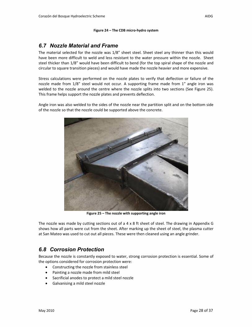
Stress calculations were performed on the nozzle plates to verify that deflection or failure of the
nozzle made from 1/8” steel would not occur. A supporting frame made from 1” angle iron was
welded to the nozzle around the centre where the nozzle splits into two sections (See Figure 25).
This frame helps support the nozzle plates and prevents deflection.
Angle iron was also welded to the sides of the nozzle near the partition split and on the bottom side
of the nozzle so that the nozzle could be supported above the concrete.
Figure 25 – The nozzle with supporting angle iron
The nozzle was made by cutting sections out of a 4 x 8 ft sheet of steel. The drawing in Appendix G
shows how all parts were cut from the sheet. After marking up the sheet of steel, the plasma cutter
at San Mateo was used to cut out all pieces. These were then cleaned using an angle grinder.
6.8 Corrosion Protection
Because the nozzle is constantly exposed to water, strong corrosion protection is essential. Some of
the options considered for corrosion protection were:
• Constructing the nozzle from stainless steel
• Painting a nozzle made from mild steel
• Sacrificial anodes to protect a mild steel nozzle
• Galvanising a mild steel nozzle

Corazón del Bosque Hydroelectric Scheme AIDG
May 2010 Page 29 of 37
The turbine nozzles made by Walsh Hydro are made from welded sheet stainless steel and this
option was seriously considered for the CDB turbine. The main disadvantage of this option however
was the high cost of stainless steel. Due to the large size of the CDB turbine, a 4 x 8 ft sheet would be
required which costs Q2,700 (US$340). A large number of stainless steel welding rods would also be
required which are also very expensive.
Painting the nozzle would have been very difficult to perform on the inside of a closed nozzle and
therefore the nozzle would have required a removable lid to paint the inside. This would have made
the design much more complicated, difficult to seal and would have increased the cost.
Sacrificial anodes were not a viable option for the nozzle because of the large surface area of the
nozzle exposed to water. A sacrificial anode would have been more viable if there was already an
insulation layer (eg. paint) to dramatically reduce the current demanded for cathodic protection. The
anodes would also have to be replaced periodically, increasing maintenance requirements.
Galvanisation was the method selected for protecting the nozzle as this provided the lowest cost
option while also providing adequate protection. The nozzle was hot dip galvanised by Grupo ITM in
Guatemala City. Cheaper electroplating could not be used because it was not possible to coat the
inside of the nozzle by electroplating. The partition plates, however, were electroplated since they
have an accessible outer surface.
7 Drive System and Generator Due to the low net head at CDB and the lower speed operation of Crossflow Turbines, the speed of
the turbine at CDB needs to be increased significantly to drive a generator. For this reason, and
because the turbine is so long and heavy, direct mounting the turbine on the generator shaft was
not an option. Instead, the turbine is mounted on separate bearings and the speed is increased using
a gearbox that then drives the generator. Flexible couplings are required between the turbine,
gearbox and generator to prevent stresses on the various component bearings.
7.1 Turbine Bearings
A bearing on each side of the CDB turbine is used to mount the turbine on the channel walls. To
select the bearing type, the forces acting on the turbine need to be calculated. The force of the
water acting on the turbine is given by:
vQ
vm
maF
ρ=
=
=
&
Where: m is mass
a is acceleration
v is velocity of the water
ρ is the density of water (1000kg/m^3)
Q is the flow in m^3/s
In the spreadsheet “CDB – Turbine Design Calculations.xls” the velocity of the water is calculated to
be 5.3 m/s and the maximum flow of the turbine is 250 L/s. Substituting these values into the above
equation the force due to the water acting on the blades is calculated to be 1325 N.
Corazón del Bosque Hydroelectric Scheme AIDG
May 2010 Page 30 of 37
The other force acting on the turbine is the weight of the turbine. The mass of the turbine was
measured as approximately 40 kg. Therefore, the weight of the turbine is approximately 400 N.
If we assume the worst case scenario where both the force due to the water and weight act in the
same direction, the total force acting on the turbine is F = 1700 N and the force acting on each
bearing is 850 N.
Harvey (1993) gives the following equation for calculating bearing life:
q
hP
C
nL
=60
106
10
Where: L10h is likely bearing life in hours
n is rotational speed in rpm
C is dynamic load rating in Newtons
P is equivalent dynamic load in Newtons
q is exponent for life equation (q = 3 for ball bearings and q = 3.3 for roller
bearings)
Because there are no axial loads acting on the turbine, P = 850 N. Rearranging the equation and
using a shaft speed of n = 180 RPM and seeking a bearing life of L10h = 20 years, C = 10,500 N for a
ball bearing and C = 8,360 N for a roller bearing.
Searching through the SKF Bearing catalogue, the SY1-TF ball bearing was selected for the CDB
turbine. This bearing is rated for a dynamic load rating of C = 14,000N which comfortably meets the
above requirements. The TF model is used as it provides a better sealing system against water spray
and dust.
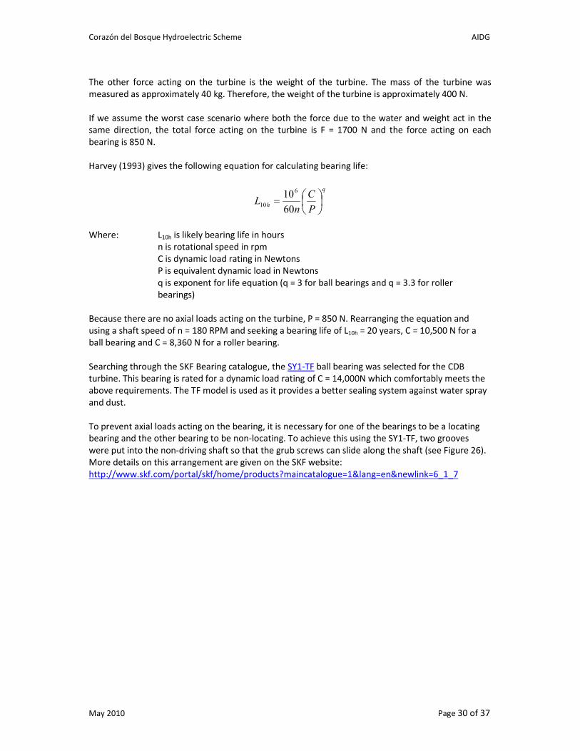
To prevent axial loads acting on the bearing, it is necessary for one of the bearings to be a locating
bearing and the other bearing to be non-locating. To achieve this using the SY1-TF, two grooves
were put into the non-driving shaft so that the grub screws can slide along the shaft (see Figure 26).
More details on this arrangement are given on the SKF website:
http://www.skf.com/portal/skf/home/products?maincatalogue=1&lang=en&newlink=6_1_7
Corazón del Bosque Hydroelectric Scheme AIDG
May 2010 Page 31 of 37
Figure 26 – One of the grooves on the non-driving turbing shaft
7.2 Generator The options investigated for a generator for the CDB micro-hydro system were:
• A DC generator
• A synchronous generator
• An induction generator
As discussed below, an induction generator was selected for the system at CDB due to the lower
cost, reliability, overspeed capability and the ability to source the generator in Guatemala.
7.2.1 DC Generator
A DC generator is a good option for very small micro-hydro systems. One of the main advantages is
that the speed at which the generator is driven at does not matter and a governor or electric load
controller is not required. A DC generator usually is used with storage batteries and this can be
useful where storage is required or where the turbine is one of many energy sources providing DC to
a common battery store.
The main disadvantage of DC generators is that they become quite expensive for schemes over 1kW.
The DC Baldor Permanent Magnet Generators (www.baldor.com) are used by Walsh Hydro in
Australia. For the 2.5kW produced at CDB, the Baldor CDP3603 would be required which costs
US$2,760. A DC:DC step down converter or an inverter and battery system would then be required
which would add further expensive to the system. The generator would also need to be imported
into Guatemala.
7.2.2 AC Synchronous Generator
Synchronous Generators are the most common generator used for AC micro-hydro systems. Due to
the relatively small size of the load at CDB, a single phase generator would be required as balancing
such small loads on a three phase system would be very difficult.

Corazón del Bosque Hydroelectric Scheme AIDG
May 2010 Page 32 of 37
The generators for micro-hydro generally spin at the slower speed of 1800 RPM (rather than 3600
RPM) and are designed for continuous operation. It is much harder to find 2 pole synchronous
generators that run at 900 RPM and these generators are generally much more expensive.
Off the shelf synchronous generators for micro-hydro applications usually need to be imported into
Guatemala. However, a supplier of AC 3kW single phase generators was found in Guatemala City
who sells the units for Q28,000 (US$3,000).
In addition to the generator, an electronic control system would be required to keep the system
operating at a constant speed and frequency. AIDG and XelaTeco have produced the Hummingbird
Controller in Guatemala in the past for the control of synchronous generators. This unit costs
approximately US$500 to produce.
Apart from the higher cost of synchronous generators, the main disadvantage of these types of
generators is that they cannot operate at overspeed. If this occurs, winding on the rotor may be
pulled out of position by the centripetal force occurring at excessive speeds. Because impulse micro-
hydro turbines generally have a runaway speed that is twice their normal operating speed, they can
cause the generator to overspeed if the load is dropped. Therefore, some type of overspeed trip is
normally required which either disconnects the generator mechanically or spoils the water entering
the turbine so that it can’t reach runaway speeds. This device complicates the design of the system
and can add significant expense.
7.2.3 AC Induction Generator
Although less common than synchronous generators, AC induction generators are increasingly being
used in small micro-hydro schemes. Their advantages are that they are easily and cheaply available
as motors, simply constructed and repaired, reliable, rugged, require little maintenance and can
withstand 100% overspeed (Harvey, 1993).
Induction generators are easily used as generators when connected to an existing grid supply. This
would be possible at CDB since they are already connected to the grid. However, since the turbine is
to be a demonstration turbine it is required to operate on a separate network and a stand-alone
self-excited induction generator was required. This is made possible by fitting a three-phase
generator with excitation capacitors so that it operates at single phase. This connection arrangement
is detailed in Nigel Smith’s book “Motors as Generators for Micro-Hydro Power”.
For a stand-alone system, voltage and frequency control is made possible by an Induction Generator
Controller (IGC). This controller is supplied by Practical Action in Peru for US$800.
Because of the lower cost, higher reliability, overspeed capability and the ability to source the
generator in Guatemala, an induction generator was selected for the system at CDB. Although it is
possible to purchase 2-pole induction motors that operate at 900 RPM, these are much harder and
expensive to source in Guatemala and do not operate as efficiently as the common 4-pole 1800 RPM
machines. Therefore, a simple 4-pole machine was sourced in Guatemala City and the IGC from
Practical Action in Peru.
7.3 Transmission
The induction generator selected for the system at CDB needs to operate at just over 1800 RPM to
generate AC at 60 Hz while the optimum speed of the turbine is between 160 and 200 RPM
depending on the flow (the net head of the turbine, and thus the operating speed, is higher at lower
flows – see Section 3.1). Therefore, the turbine speed needs to be increased by a ratio of 10:1.
Corazón del Bosque Hydroelectric Scheme AIDG
May 2010 Page 33 of 37
Some of the transmission options that were investigated where:
• A pulley system
• Purchasing an induction motor with built-on gearbox
• Purchasing a separate gearbox
Pulley systems are commonly used in micro-hydro systems where the speed ration is 3:1 or less.
However, because of the high speed ratio at CDB, a double pulley system would be required which
would result in high losses. As well as being less efficient, a double pulley system was estimated to
be more expensive and more difficult to install than a gearbox.
An induction motor with gearbox was searched for in Guatemala. However, no motor and gearbox
with the correct specifications was found.
The final option that was adopted at CDB was to purchase a separate gearbox. The gearbox selected
was imported from the FTP Group in England (see Appendix C) and has a speed ratio of 10.9:1.
Although the cost of this component was significant (GBP627 = US$964), this option proved to be
less expensive than the double pulley system and more efficient (97.4%).
7.4 Flexible Coupling
Flexible couplings were required to connect the shafts of the turbine, gearbox and generator as any
attempt to connect the shafts with a strong rigid coupling would give rise to bending of the shafts,
fatigue failure and very high loads on the bearings.
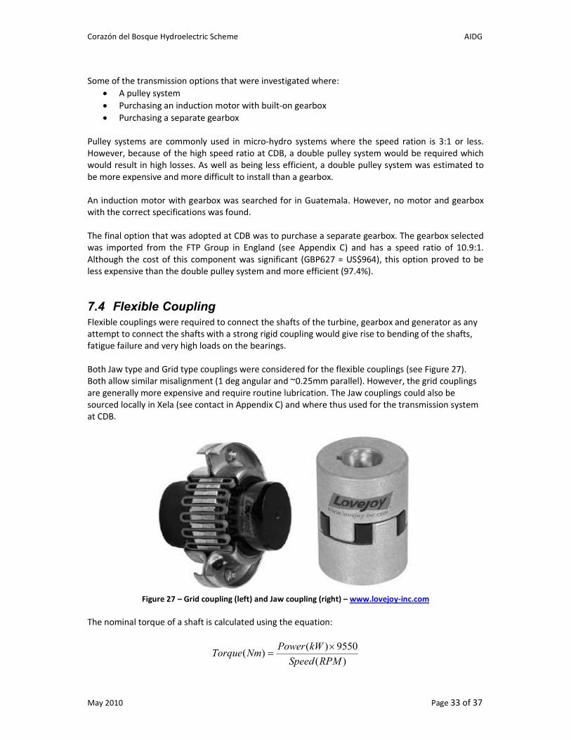
Both Jaw type and Grid type couplings were considered for the flexible couplings (see Figure 27).
Both allow similar misalignment (1 deg angular and ~0.25mm parallel). However, the grid couplings
are generally more expensive and require routine lubrication. The Jaw couplings could also be
sourced locally in Xela (see contact in Appendix C) and where thus used for the transmission system
at CDB.
Figure 27 – Grid coupling (left) and Jaw coupling (right) – www.lovejoy-inc.com
The nominal torque of a shaft is calculated using the equation:
)(
9550)()(
RPMSpeed
kWPowerNmTorque
×=

Corazón del Bosque Hydroelectric Scheme AIDG
May 2010 Page 34 of 37
Using a turbine shaft power of 3 kW, the turbine shaft operates at a much higher torque (187 Nm)
than the generator shaft (16.6 Nm) due to its lower speed. Therefore, the coupling selected for the
turbine shaft (L225) is much larger than that used for the generator shaft (L100). The couplings were
selected from the LoveJoy Jaw Coupling Catalogue (http://www.lovejoy-inc.com) and were modified
by the machinists at Tornos Gutierrez for the various shaft sizes.
7.5 Mounting and Shaft Alignment The Gearbox and Generator are mounted on a cement block of pure grout. The components were
positioned and bolted to the cement block using concrete expansion bolts.
The shafts and couplings of the different components were aligned using the instructions given on
the LoveJoy website:
http://www.lovejoy-inc.com/uploadedFiles/Technical_Resources/JawInstruction.pdf
Shims made from thin galvanised sheet metal were used to adjust the feet of the gearbox and
generator and feeler gauges and Vernier Callipers were used to verify the alignment.
8 Fabrication and Lessons Learnt
8.1 Wobble in Turbine Runner
The largest mistake in the design of the CDB turbine runner was the use of two separate shafts
rather than one single straight shaft. The turbine was made with the end plates not exactly parallel
to each other and when the shaft hubs were mounted on these plates the shafts were not parallel.
This led to a wobble in the shaft that would have caused a significant cyclic misalignment between
the turbine shaft and the gearbox shaft.
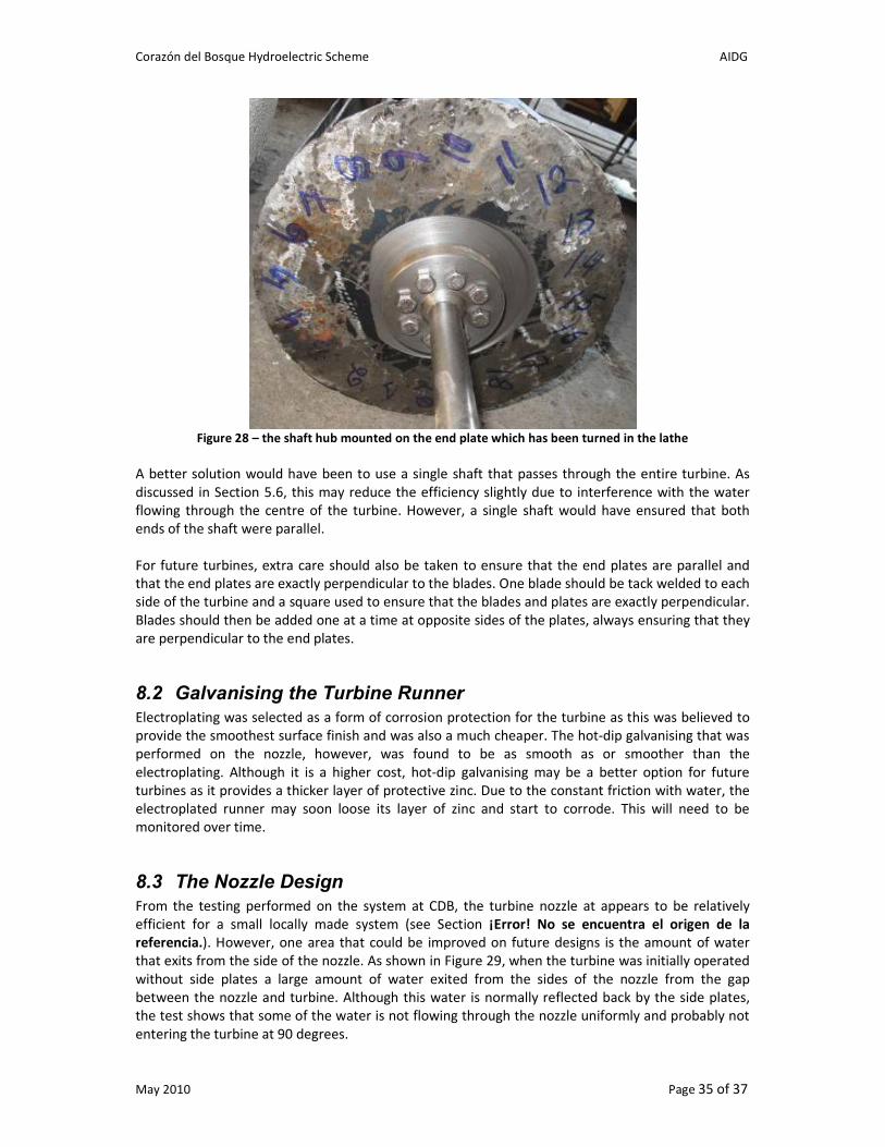
To rectify the problem with the non-parallel end discs and shafts, the entire turbine was placed in a
lathe and the discs turned so that the middle sections where the hubs are mounted were parallel
(the cut section of the disc is shown by the shiny section in Figure 28). These sections cut into the
discs were about 3 mm deep at the deepest point. If we would have had to cut any more, the 6 mm
thick end plates would have been significantly weakened.
Corazón del Bosque Hydroelectric Scheme AIDG
May 2010 Page 35 of 37
Figure 28 – the shaft hub mounted on the end plate which has been turned in the lathe
A better solution would have been to use a single shaft that passes through the entire turbine. As
discussed in Section 5.6, this may reduce the efficiency slightly due to interference with the water
flowing through the centre of the turbine. However, a single shaft would have ensured that both
ends of the shaft were parallel.
For future turbines, extra care should also be taken to ensure that the end plates are parallel and
that the end plates are exactly perpendicular to the blades. One blade should be tack welded to each
side of the turbine and a square used to ensure that the blades and plates are exactly perpendicular.
Blades should then be added one at a time at opposite sides of the plates, always ensuring that they
are perpendicular to the end plates.
8.2 Galvanising the Turbine Runner
Electroplating was selected as a form of corrosion protection for the turbine as this was believed to
provide the smoothest surface finish and was also a much cheaper. The hot-dip galvanising that was
performed on the nozzle, however, was found to be as smooth as or smoother than the
electroplating. Although it is a higher cost, hot-dip galvanising may be a better option for future
turbines as it provides a thicker layer of protective zinc. Due to the constant friction with water, the
electroplated runner may soon loose its layer of zinc and start to corrode. This will need to be
monitored over time.
8.3 The Nozzle Design
From the testing performed on the system at CDB, the turbine nozzle at appears to be relatively
efficient for a small locally made system (see Section ¡Error! No se encuentra el origen de la
referencia.). However, one area that could be improved on future designs is the amount of water
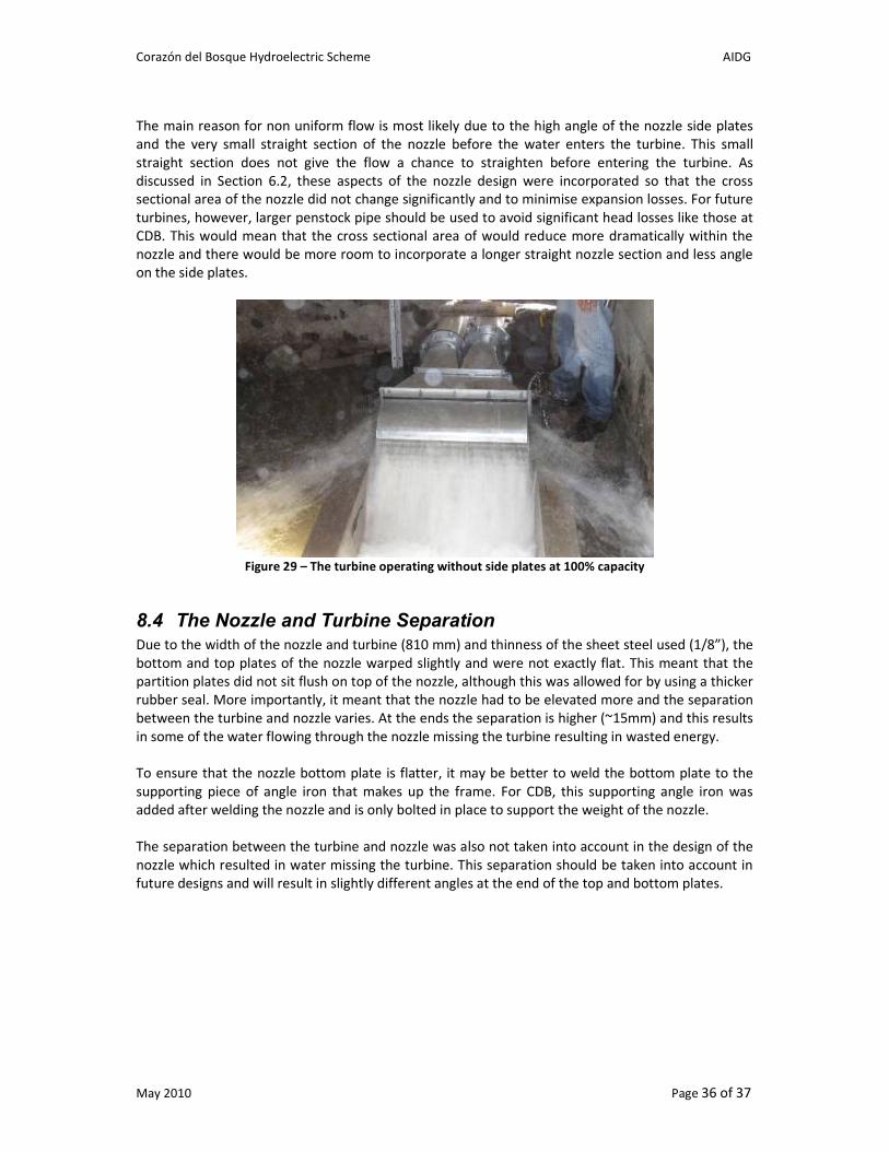
that exits from the side of the nozzle. As shown in Figure 29, when the turbine was initially operated
without side plates a large amount of water exited from the sides of the nozzle from the gap
between the nozzle and turbine. Although this water is normally reflected back by the side plates,
the test shows that some of the water is not flowing through the nozzle uniformly and probably not
entering the turbine at 90 degrees.
Corazón del Bosque Hydroelectric Scheme AIDG
May 2010 Page 36 of 37
The main reason for non uniform flow is most likely due to the high angle of the nozzle side plates
and the very small straight section of the nozzle before the water enters the turbine. This small
straight section does not give the flow a chance to straighten before entering the turbine. As
discussed in Section 6.2, these aspects of the nozzle design were incorporated so that the cross
sectional area of the nozzle did not change significantly and to minimise expansion losses. For future
turbines, however, larger penstock pipe should be used to avoid significant head losses like those at
CDB. This would mean that the cross sectional area of would reduce more dramatically within the
nozzle and there would be more room to incorporate a longer straight nozzle section and less angle
on the side plates.
Figure 29 – The turbine operating without side plates at 100% capacity
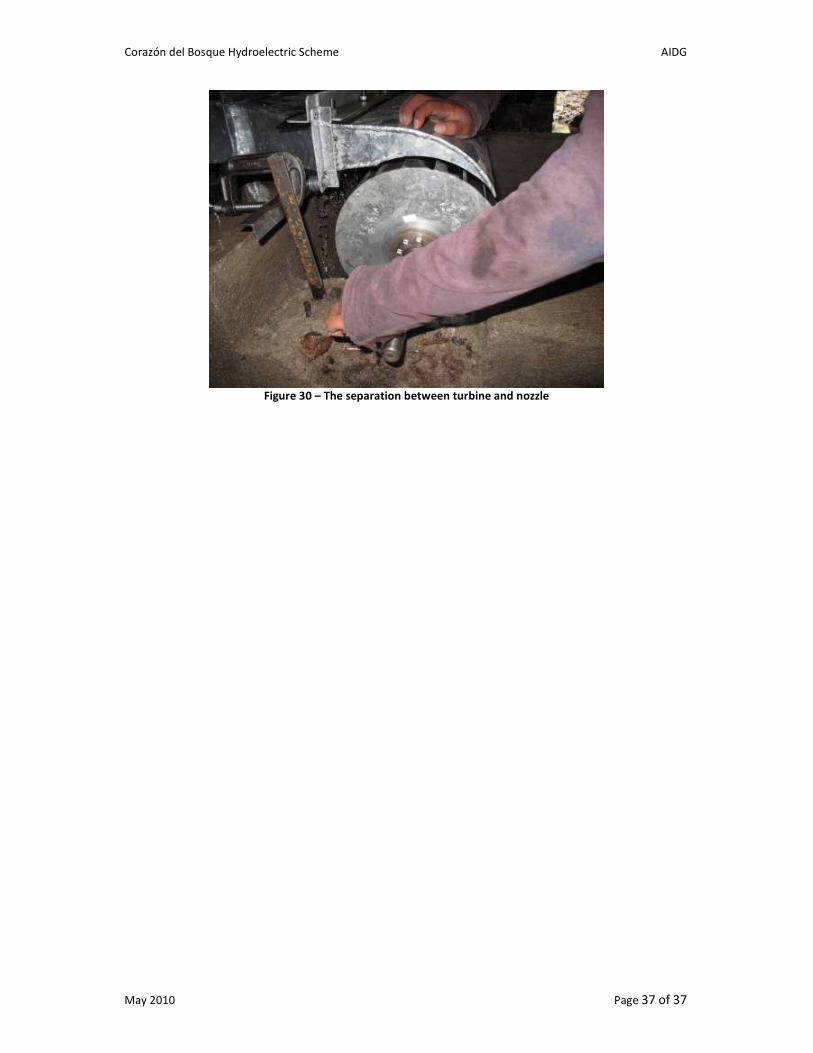
8.4 The Nozzle and Turbine Separation Due to the width of the nozzle and turbine (810 mm) and thinness of the sheet steel used (1/8”), the
bottom and top plates of the nozzle warped slightly and were not exactly flat. This meant that the
partition plates did not sit flush on top of the nozzle, although this was allowed for by using a thicker
rubber seal. More importantly, it meant that the nozzle had to be elevated more and the separation
between the turbine and nozzle varies. At the ends the separation is higher (~15mm) and this results
in some of the water flowing through the nozzle missing the turbine resulting in wasted energy.
To ensure that the nozzle bottom plate is flatter, it may be better to weld the bottom plate to the
supporting piece of angle iron that makes up the frame. For CDB, this supporting angle iron was
added after welding the nozzle and is only bolted in place to support the weight of the nozzle.
The separation between the turbine and nozzle was also not taken into account in the design of the
nozzle which resulted in water missing the turbine. This separation should be taken into account in
future designs and will result in slightly different angles at the end of the top and bottom plates.
Corazón del Bosque Hydroelectric Scheme AIDG
May 2010 Page 37 of 37
Figure 30 – The separation between turbine and nozzle