Embed Size (px)
Citation preview
Copyright © 2014 Delmar, Cengage Learning
Diesel Engine Electronics
Instructor Name: (Your Name)
14CHAPTER

Copyright © 2014 Delmar, Cengage Learning
Learning Objectives
• Discuss the various types of electronically controlled diesel fuel systems
• Describe why the current flow through an inductor can not instantly change
• Explain the fundamentals of a closed loop control system
• Discuss how an in-range failure might not cause a DTC to be set
Copyright © 2014 Delmar, Cengage Learning
Learning Objectives (continued)
• Explain the difference between in-cylinder emission reduction and exhaust aftertreatment
• Discuss how a variable geometry turbocharger can be used to regulate EGR flow rate
• Explain how particulate matter and NOx
exhaust emissions are controlled• Describe the requirements for HD-OBD and
discuss some of the benefits of this regulation for technicians

Copyright © 2014 Delmar, Cengage Learning
Electronically Controlled Engine
• Particulate Matter (PM) – Exhaust smoke
• Oxides of Nitrogen (NOx) – One of the pollutants responsible for smog
• Electronic Control Module (ECM) –Computer that controls engine fuel system

Copyright © 2014 Delmar, Cengage Learning
Typical 2010 Engine Wiring Harness
Figure 14-1 Typical 2010 engine wiring harness.

Copyright © 2014 Delmar, Cengage Learning
The Basic Tasks of a Diesel Fuel System
• Provide injection metering• Atomize the fuel • Provide injection timing control• Control fuel delivery independent of
engine speed and cam shaft geometry• Perform multiple injection events per cycle

Copyright © 2014 Delmar, Cengage Learning
Bosch RE30 Electronically Controlled Rack Actuator
Figure 14-5 Bosch RE30 electronically controlled rack actuator.
Copyright © 2014 Delmar, Cengage Learning
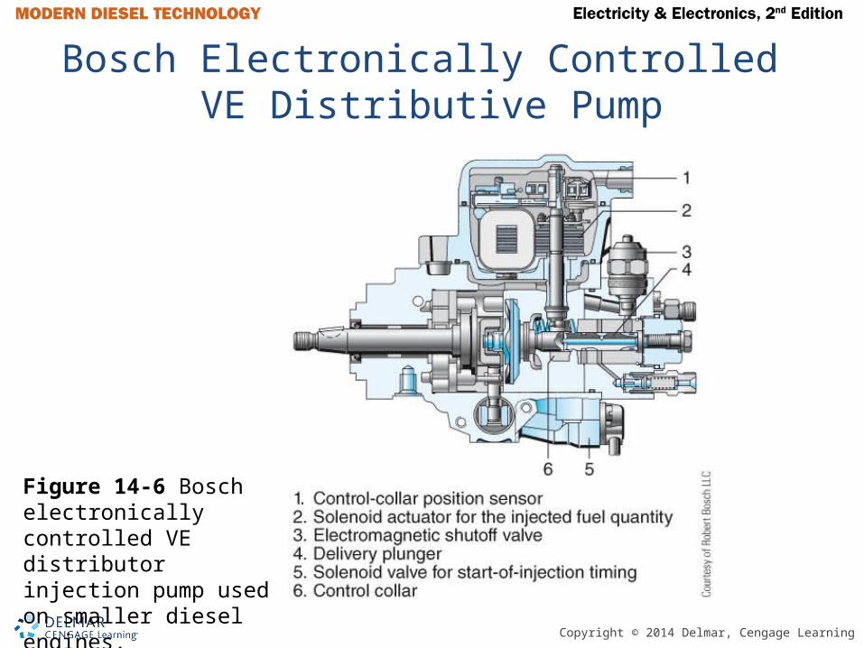
Bosch Electronically Controlled VE Distributive Pump
Figure 14-6 Bosch electronically controlled VE distributor injection pump used on smaller diesel engines.

Copyright © 2014 Delmar, Cengage Learning
Electronic Unit Injector (EUI)
• NOP – Nozzle opening pressure• NCV – Needle control valve• SV – Spill valve• EUP – Electronic unit pump• Pilot Injection – Small amount of fuel
injected in combustion chamber prior to main injection
Copyright © 2014 Delmar, Cengage Learning
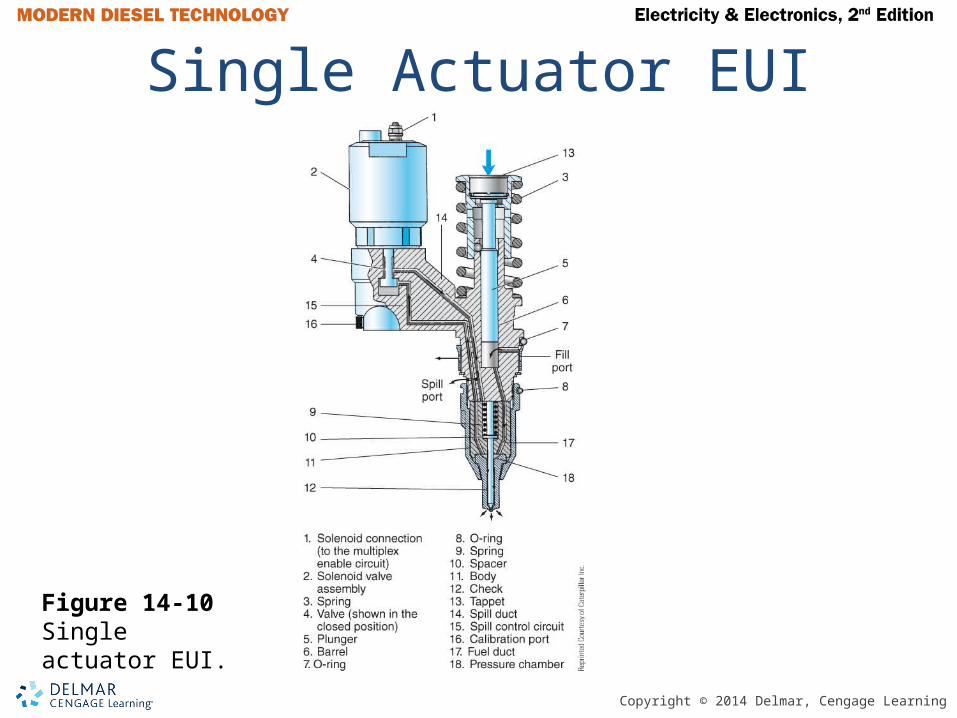
Single Actuator EUI
Figure 14-10 Single actuator EUI.

Copyright © 2014 Delmar, Cengage Learning
Important Fact
The current flow through an inductor cannot change instantly from level to another. However, the voltage measured across an inductor can instantly change from one level to another.

Copyright © 2014 Delmar, Cengage Learning
Figure 14-12 Instantaneous current rise ina resistor circuit.
Figure 14-13 Ramped current rise in inductor circuit
Current Rise

Copyright © 2014 Delmar, Cengage Learning
Delphi E3 Dual Actuator EUI
Figure 14-15 Delphi E3 dual actuator EUI.

Copyright © 2014 Delmar, Cengage Learning
Nozzle Can Open When NCV is Energized
Figure 14-16 Nozzle opens when NCV is energized.

Copyright © 2014 Delmar, Cengage Learning
Electronic Unit Pump (EUP)
Figure 14-17 Electronic unit pump.

Copyright © 2014 Delmar, Cengage Learning
Main Components of a HEUI System
• High pressure oil pump develops the high pressure engine oil called injection control pressure (ICP)
• Injection pressure regulator (IPR)• ICP sensor• Electronic unit injectors (EUI)• High pressure oil manifold

Copyright © 2014 Delmar, Cengage Learning
Navistar HEUI Pressure Control System Components
Figure 14-18 Navistar HEUI injection pressure control system components.
Copyright © 2014 Delmar, Cengage Learning
Closed Loop Circuit
• ECM knows the desired injection control pressure
• ECM knows the measured or actual injection control pressure
• Measured injection control pressure can be changed by increasing or decreasing the duty cycle of the injection pressure regulator
Copyright © 2014 Delmar, Cengage Learning
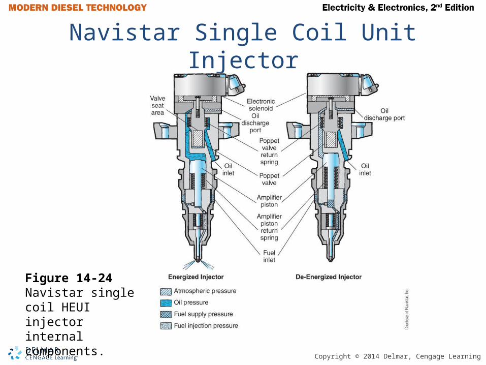
Navistar Single Coil Unit Injector
Figure 14-24 Navistar single coil HEUI injector internal components.
Copyright © 2014 Delmar, Cengage Learning
CAUTION
Follow the OEM’s specific safety recommendations when troubleshooting any electronically controlled diesel fuel system to prevent fatal electric shock.
Copyright © 2014 Delmar, Cengage Learning
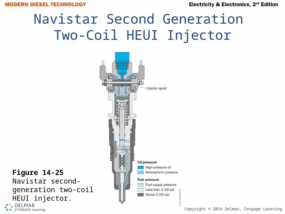
Navistar Second Generation Two-Coil HEUI Injector
Figure 14-25 Navistar second-generation two-coil HEUI injector.

Copyright © 2014 Delmar, Cengage Learning
WARNING
Never crack common rail fuel lines open with the engine running for any reason, including checking for a misfiring cylinder. Doing so could cause fuel under extreme pressure to penetrate your skin resulting in death or serious injury. Follow OEM instruction for rail pressure bleed down before loosening any components in the high-pressure fuel system. Never install a standard pressure gauge in a common rail system. The extreme pressure will cause the gauge to explode.

Copyright © 2014 Delmar, Cengage Learning
Caterpillar Common Rail Fuel System
Figure 14-27 Caterpillar common rail fuel system.
Copyright © 2014 Delmar, Cengage Learning
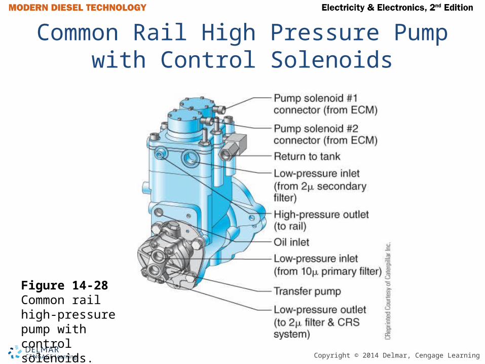
Common Rail High Pressure Pump with Control Solenoids
Figure 14-28 Common rail high-pressure pump with control solenoids.

Copyright © 2014 Delmar, Cengage Learning
Solenoid Controlled Common Rail Injector Nozzle
Figure 14-29 Solenoid-controlled common rail injector nozzle.

Copyright © 2014 Delmar, Cengage Learning
Piezo Actuated Common Rail Injector
Figure 14-30 Piezo-actuated common rail injector.

Copyright © 2014 Delmar, Cengage Learning
In Cylinder Exhaust Emission Reduction
• EGR – Exhaust gas recirculation• VGT – Variable geometry turbocharger• Smart Actuator – An actuator that contains
a microprocessor and communication interface
• Virtual Sensor – Estimated value obtained from mechanical models of the system
• Learn Cycle – Actuator is driven from minimum to maximum span at start up

Copyright © 2014 Delmar, Cengage Learning
Typical Cooled EGR System With VGT Turbocharger
Figure 14-31 Typical cooled EGR system with VGT.

Copyright © 2014 Delmar, Cengage Learning
Electrohydraulic VGT Actuator
Figure 14-32 Electrohydraulic VGT actuator.

Copyright © 2014 Delmar, Cengage Learning
Diesel After Treatment
• Aftertreatment – Modification of exhaust gasses after they leave the combustion chamber
• DPF – Diesel particulate filter• DOC – Diesel oxidization catalyst• SCR – Selective catalyst reduction• DEF – Diesel exhaust fluid
Copyright © 2014 Delmar, Cengage Learning
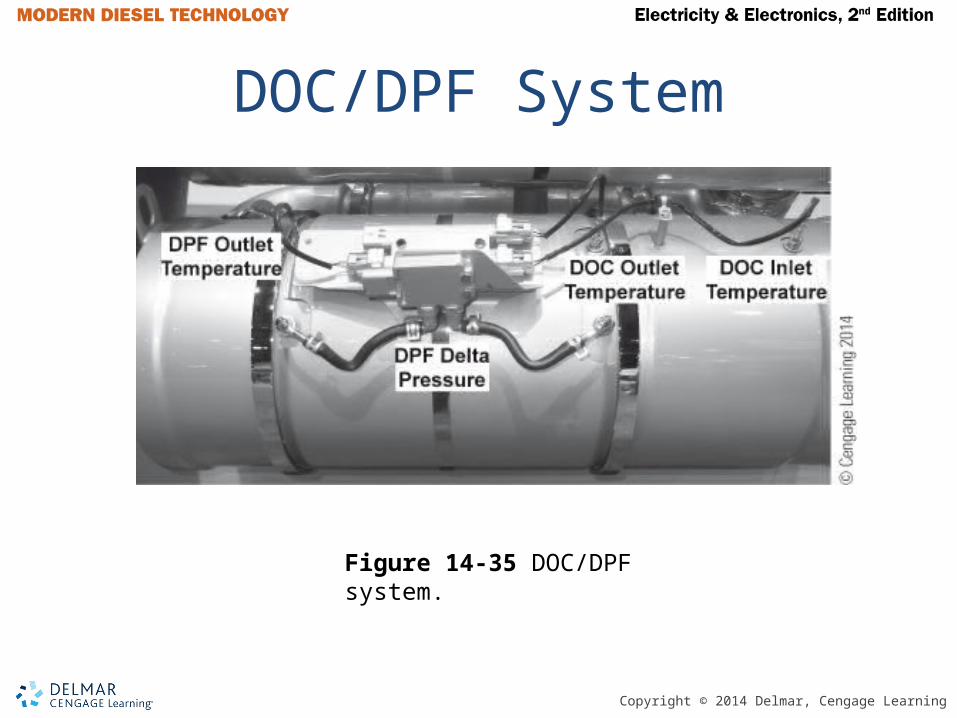
DOC/DPF System
Figure 14-35 DOC/DPF system.
Copyright © 2014 Delmar, Cengage Learning
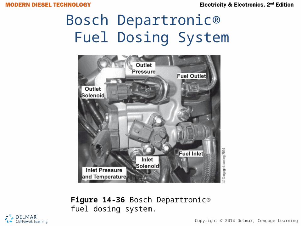
Bosch Departronic® Fuel Dosing System
Figure 14-36 Bosch Departronic® fuel dosing system.

Copyright © 2014 Delmar, Cengage Learning
Caterpillar CRS System
Figure 14-37 Caterpillar CRS system. Compressed air is used to purge the injector and to aid in combustion.

Copyright © 2014 Delmar, Cengage Learning
Caterpillar CRS Injector and Spark Plug Assembly
Figure 14-38 Caterpillar CRS injector and spark plug details. Engine coolant is used to cool the injector.

Copyright © 2014 Delmar, Cengage Learning
SCR System Components
Figure 14-39 SCR system components.
Copyright © 2014 Delmar, Cengage Learning
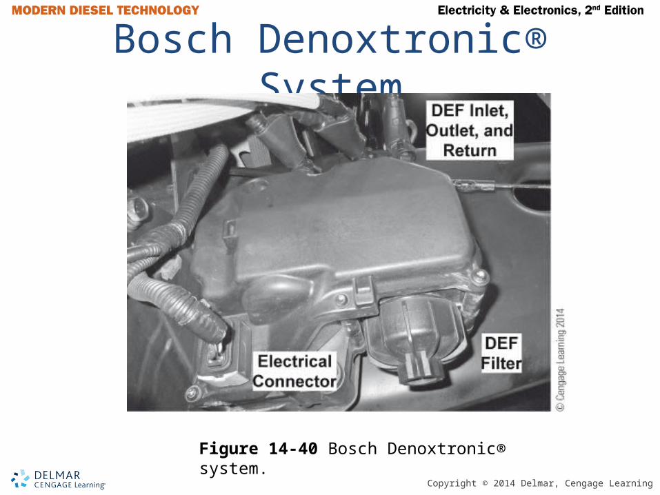
Bosch Denoxtronic® System
Figure 14-40 Bosch Denoxtronic® system.
Copyright © 2014 Delmar, Cengage Learning
Heavy Duty On-Board Diagnostics
• HD-OBD – Heavy duty on board diagnostics• MIL – Malfunction indicator lamp• Started coming into effect in 2010• Pending DTC – ECM first detects an
emissions related malfunction; MIL will not illuminate
• Detected DTC – The pending DTC is detected on second drive cycle; MIL will illuminate

Copyright © 2014 Delmar, Cengage Learning
Pro Link 9000 EST
Figure 14-42 Pro-Link 9000 scan tool.

Copyright © 2014 Delmar, Cengage Learning
PC Based EST
Figure 14-43 PC-based electronic service tool.

Copyright © 2014 Delmar, Cengage Learning
Injector Cut Out Test Result
Figure 14-44 Injector cutout test results indicate a problem with #2 cylinder.
Copyright © 2014 Delmar, Cengage Learning
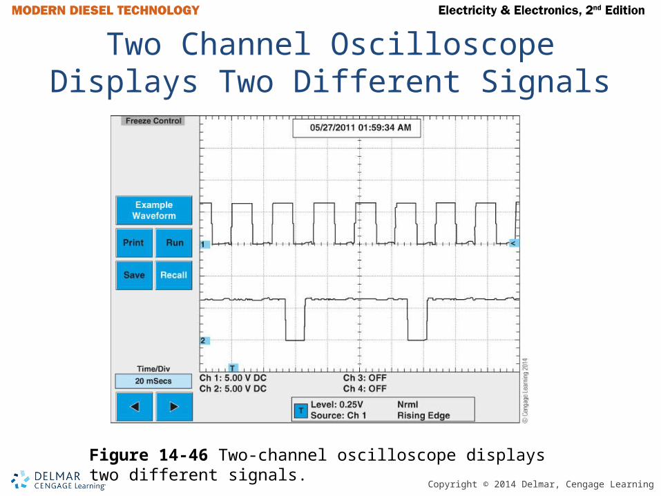
Two Channel Oscilloscope Displays Two Different Signals
Figure 14-46 Two-channel oscilloscope displays two different signals.
Copyright © 2014 Delmar, Cengage Learning
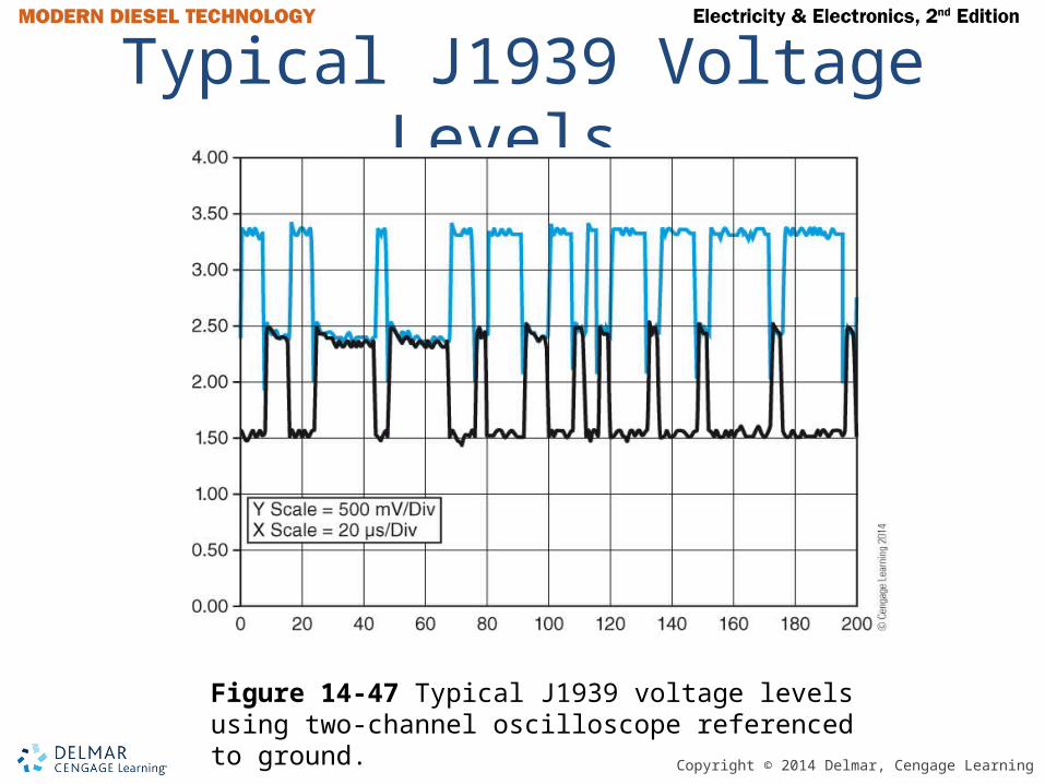
Typical J1939 Voltage Levels
Figure 14-47 Typical J1939 voltage levels using two-channel oscilloscope referenced to ground.

Copyright © 2014 Delmar, Cengage Learning
Summary• Vehicles with diesel engines sold in the
U.S. are subject to EPA exhaust emissions regulations. These regulations have resulted in substantial decreases of particulate matter and oxides of nitrogen emissions. To attain these requirements , electronic engine controls were necessary.
• Electronic unit injector (EUI) systems with single actuators control the spill valve opening and closing. Dual-actuator EUIs control both the spill valve and the nozzle opening.

Copyright © 2014 Delmar, Cengage Learning
Summary (continued)• Self-inductance prevents the current flow
through an inductor from changing quickly.• Hydraulically actuated electronic unit
injectors amplify engine lubrication oil under pressure to generate injection pressures.
• A closed loop control system compares a desired output to the measured output referred to as the error. A controller drives the output such that the error becomes zero, indicating the desired output and the measured output are the same. Closed loop systems are used in a variety of trucks.

Copyright © 2014 Delmar, Cengage Learning
Summary (continued)
• An in-range failure is a condition where the input voltage at an electronic control module is within the normal operating voltage range, but does not correctly represent what is being measured.
• Exhaust emissions can be controlled by a combination of in-cylinder techniques and by exhaust aftertreatment systems.
• A variable geometry turbocharger (VGT) can be used to regulate EGR flow.
Copyright © 2014 Delmar, Cengage Learning
Summary (continued)
• An H-bridge is an electronic circuit that causes the polarity of two wires to reverse to permit directional control of a electric motor.
• Soot is captured in a DPF. A periodic regeneration of the filter to oxidize the soot is sometimes necessary. Heat for the regeneration is produced either by diesel fuel being injected over a DOC or by igniting the fuel in a burner in the exhaust.

Copyright © 2014 Delmar, Cengage Learning
Summary (continued)
• SCR uses ammonia to reduce NOx. The ammonia is produced when an urea water solution called DEF is injected into the exhaust stream.
• HD-OBD describes the ability of a diesel engine to determine that its emissions have exceeded a threshold and to illuminate a MIL to alert the driver.