Embed Size (px)
Citation preview
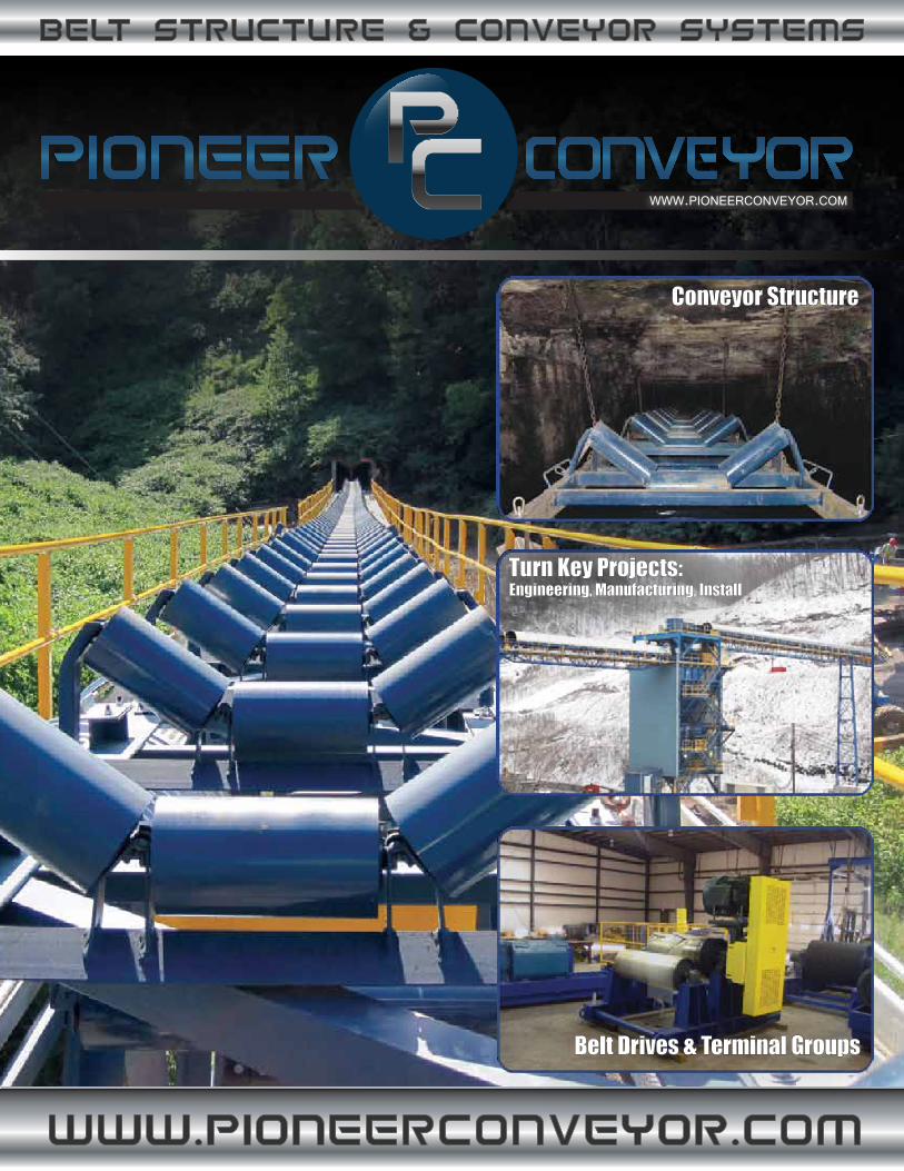
Turn Key Projects:Engineering, Manufacturing, Install
Belt Drives & Terminal Groups
Conveyor StructureConveyor Structure
2
Pioneer Conveyor is a leading bulk material conveyor manufacturing firm serving customers throughout North America and across the globe. Pioneer has designed and manufacturedthousands of standard and custom conveyor systems for a multitude of applications.
Pioneer has complete engineering, machining, fabrication, and manufacturing departmentson-site to design and manufacture your next conveyor project. Pioneer Conveyor is a certified CEMA (Conveyor Equipment Manufacturers Association) member www.cemanet.org. All of Pioneer Conveyor’s products are designed and manufactured significantly above required CEMAspecification requirements. This allows Pioneer to offer our customers the most attractivewarranty in the industry.
Pioneer Conveyor’s mission is to raise the bar for the worldwide conveyor systems one customer at a time. “Our success will be measured by our ability to increase the expectations of allconveyor system consumers so that they will never settle for anything less than receiving the highest quality products at a great price, custom engineered for their unique applications,delivered on-time, and monitored closely by the regional sales engineers.”
Give us a call and have one of our Sales Engineers visit your site, to discuss your conveyorrequirements!
TECHNICAL INFOPIONEER STYLECATENARY STYLEIMPACT STRUCTURERETRO-FITTERMINAL GROUPSTURN KEY PROJECTSINLINE STRUCTURE
3-46-9
10-1112
13-1415-1616-1718-22
3
TECH
NIC
AL IN
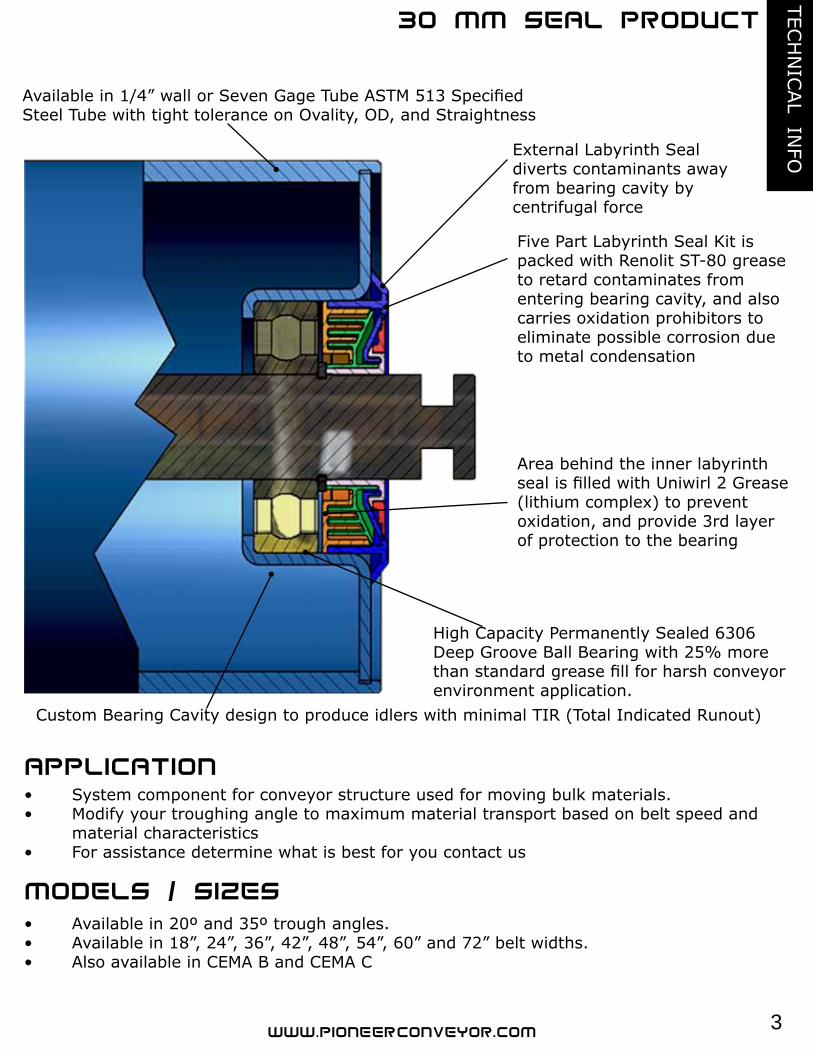
FOExternal Labyrinth Seal diverts contaminants away from bearing cavity by centrifugal force
Five Part Labyrinth Seal Kit is packed with Renolit ST-80 grease to retard contaminates from entering bearing cavity, and also carries oxidation prohibitors to eliminate possible corrosion due to metal condensation
Area behind the inner labyrinth seal is filled with Uniwirl 2 Grease (lithium complex) to preventoxidation, and provide 3rd layer of protection to the bearing
High Capacity Permanently Sealed 6306 Deep Groove Ball Bearing with 25% more than standard grease fill for harsh conveyor environment application.
Custom Bearing Cavity design to produce idlers with minimal TIR (Total Indicated Runout)
Available in 1/4” wall or Seven Gage Tube ASTM 513 Specified Steel Tube with tight tolerance on Ovality, OD, and Straightness
• Available in 20º and 35º trough angles.• Available in 18”, 24”, 36”, 42”, 48”, 54”, 60” and 72” belt widths.• Also available in CEMA B and CEMA C
• System component for conveyor structure used for moving bulk materials.• Modify your troughing angle to maximum material transport based on belt speed and material characteristics• For assistance determine what is best for you contact us
4
TECH
NIC
AL
IN
FO
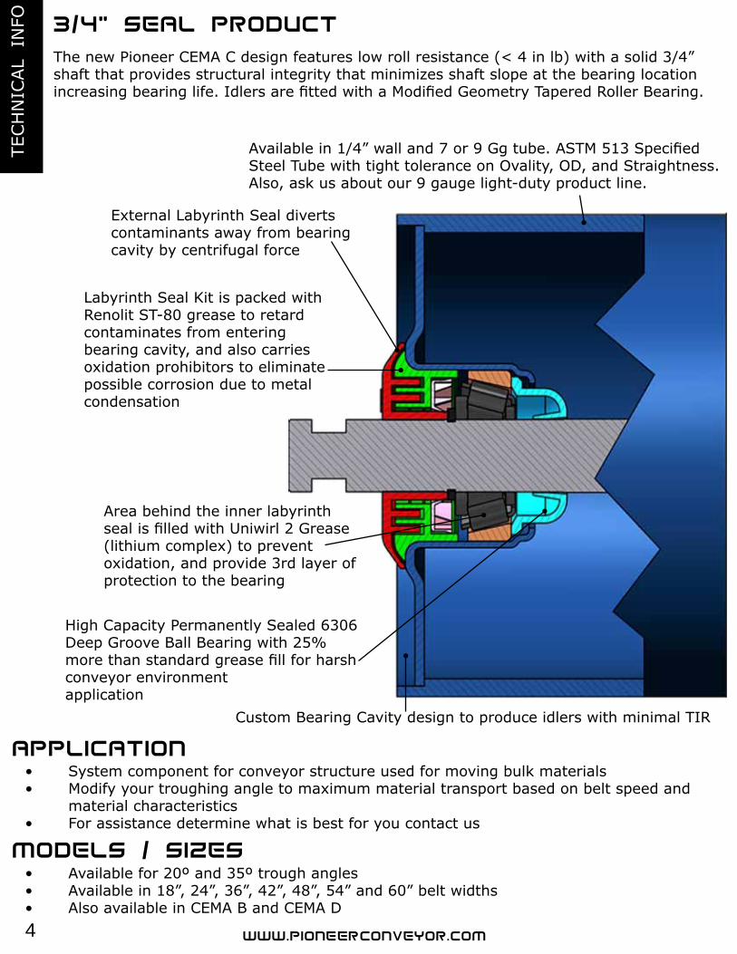
The new Pioneer CEMA C design features low roll resistance (< 4 in lb) with a solid 3/4” shaft that provides structural integrity that minimizes shaft slope at the bearing locationincreasing bearing life. Idlers are fitted with a Modified Geometry Tapered Roller Bearing.
Custom Bearing Cavity design to produce idlers with minimal TIR
• Available for 20º and 35º trough angles• Available in 18”, 24”, 36”, 42”, 48”, 54” and 60” belt widths• Also available in CEMA B and CEMA D
• System component for conveyor structure used for moving bulk materials• Modify your troughing angle to maximum material transport based on belt speed and material characteristics• For assistance determine what is best for you contact us
Labyrinth Seal Kit is packed with Renolit ST-80 grease to retard contaminates from entering bearing cavity, and also carriesoxidation prohibitors to eliminate possible corrosion due to metal condensation
External Labyrinth Seal diverts contaminants away from bearing cavity by centrifugal force
Available in 1/4” wall and 7 or 9 Gg tube. ASTM 513 Specified Steel Tube with tight tolerance on Ovality, OD, and Straightness. Also, ask us about our 9 gauge light-duty product line.
Area behind the inner labyrinth seal is filled with Uniwirl 2 Grease (lithium complex) to preventoxidation, and provide 3rd layer of protection to the bearing
High Capacity Permanently Sealed 6306 Deep Groove Ball Bearing with 25% more than standard grease fill for harsh conveyor environmentapplication
5
TECH
NIC
AL IN
FO
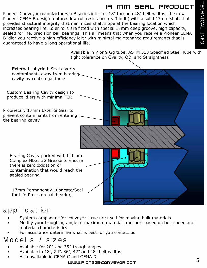
Pioneer Conveyor manufactures a B series idler for 18” through 48” belt widths, the new Pioneer CEMA B design features low roll resistance (< 3 in lb) with a solid 17mm shaft that provides structural integrity that minimizes shaft slope at the bearing location whichincreases bearing life. Idler rolls are fitted with special 17mm deep groove, high capacity, sealed for life, precision ball bearings. This all means that when you receive a Pioneer CEMA B idler you receive a high efficiency idler with minimal maintenance requirements that is guaranteed to have a long operational life.
Available in 7 or 9 Gg tube, ASTM 513 Specified Steel Tube with tight tolerance on Ovality, OD, and Straightness
External Labyrinth Seal divertscontaminants away from bearingcavity by centrifugal force
Custom Bearing Cavity design to produce idlers with minimal TIR
Proprietary 17mm Exterior Seal to prevent contaminants from entering the bearing cavity
Bearing Cavity packed with Lithium Complex NLGI #2 Grease to ensure there is zero oxidation orcontamination that would reach the sealed bearing
17mm Permanently Lubricate/Seal for Life Precision ball bearing.
application• System component for conveyor structure used for moving bulk materials• Modify your troughing angle to maximum material transport based on belt speed and material characteristics• For assistance determine what is best for you contact us
Models / sizes• Available for 20º and 35º trough angles• Available in 18”, 24”, 36”, 42” and 48” belt widths• Also available in CEMA C and CEMA D
6
PIO
NEE
R S
TYLE
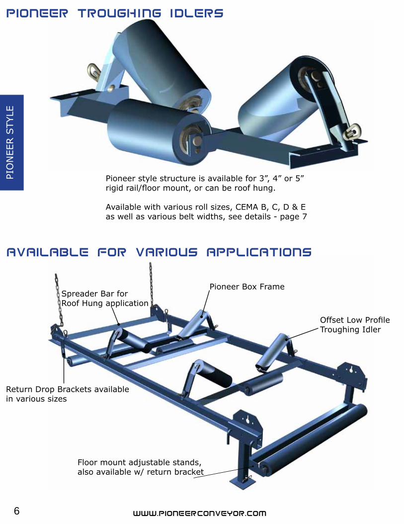
Floor mount adjustable stands, also available w/ return bracket
Spreader Bar for Roof Hung application
Return Drop Brackets availablein various sizes
Offset Low ProfileTroughing Idler
Pioneer Box Frame
Pioneer style structure is available for 3”, 4” or 5” rigid rail/floor mount, or can be roof hung.
Available with various roll sizes, CEMA B, C, D & E as well as various belt widths, see details - page 7
7
PION
EER S
TYLE
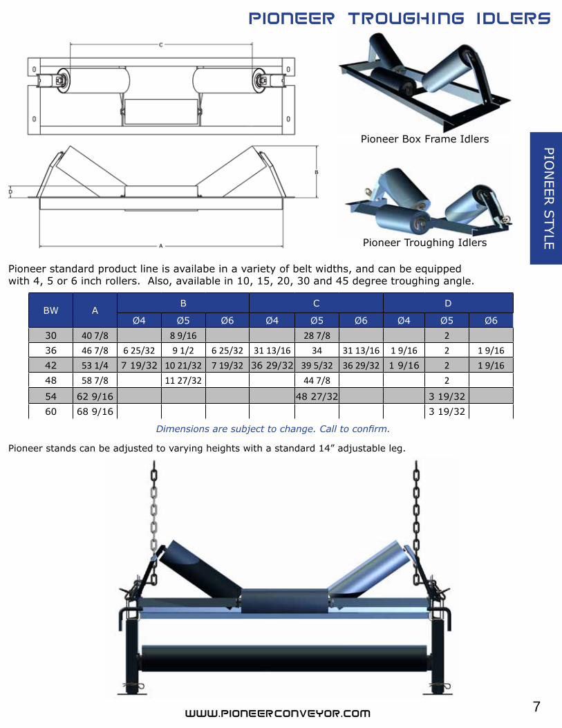
BW AB C D
Ø4 Ø5 Ø6 Ø4 Ø5 Ø6 Ø4 Ø5 Ø630 40 7/8 8 9/16 28 7/8 236 46 7/8 6 25/32 9 1/2 6 25/32 31 13/16 34 31 13/16 1 9/16 2 1 9/1642 53 1/4 7 19/32 10 21/32 7 19/32 36 29/32 39 5/32 36 29/32 1 9/16 2 1 9/1648 58 7/8 11 27/32 44 7/8 2
54 62 9/16 48 27/32 3 19/3260 68 9/16 3 19/32
Pioneer Box Frame Idlers
Pioneer Troughing Idlers
Pioneer standard product line is availabe in a variety of belt widths, and can be equipped with 4, 5 or 6 inch rollers. Also, available in 10, 15, 20, 30 and 45 degree troughing angle.
Pioneer stands can be adjusted to varying heights with a standard 14” adjustable leg.
Dimensions are subject to change. Call to confirm.
8
PIO
NEE
R S
TYLE
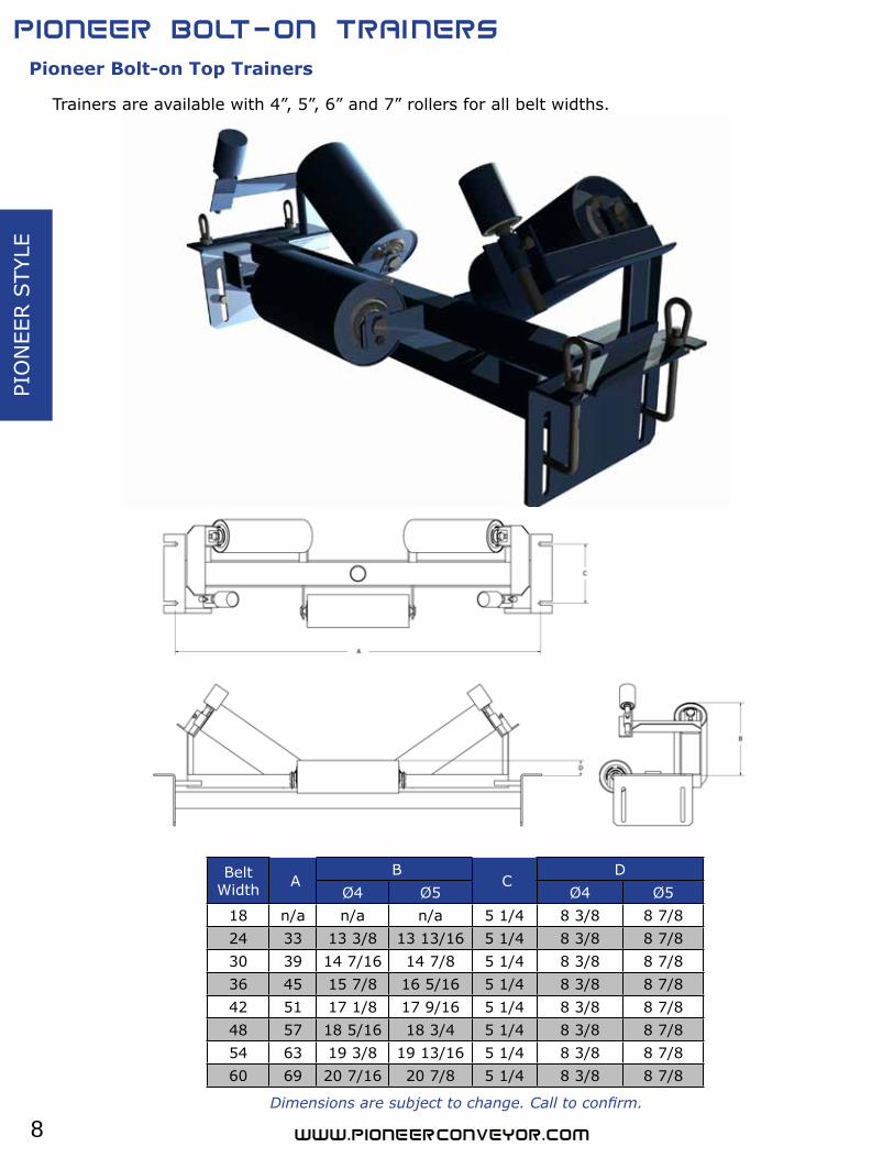
Pioneer Bolt-on Top Trainers
Trainers are available with 4”, 5”, 6” and 7” rollers for all belt widths.
Belt Width A
B C
DØ4 Ø5 Ø4 Ø5
18 n/a n/a n/a 5 1/4 8 3/8 8 7/824 33 13 3/8 13 13/16 5 1/4 8 3/8 8 7/830 39 14 7/16 14 7/8 5 1/4 8 3/8 8 7/836 45 15 7/8 16 5/16 5 1/4 8 3/8 8 7/842 51 17 1/8 17 9/16 5 1/4 8 3/8 8 7/848 57 18 5/16 18 3/4 5 1/4 8 3/8 8 7/854 63 19 3/8 19 13/16 5 1/4 8 3/8 8 7/860 69 20 7/16 20 7/8 5 1/4 8 3/8 8 7/8
Dimensions are subject to change. Call to confirm.
9
PION
EER S
TYLE
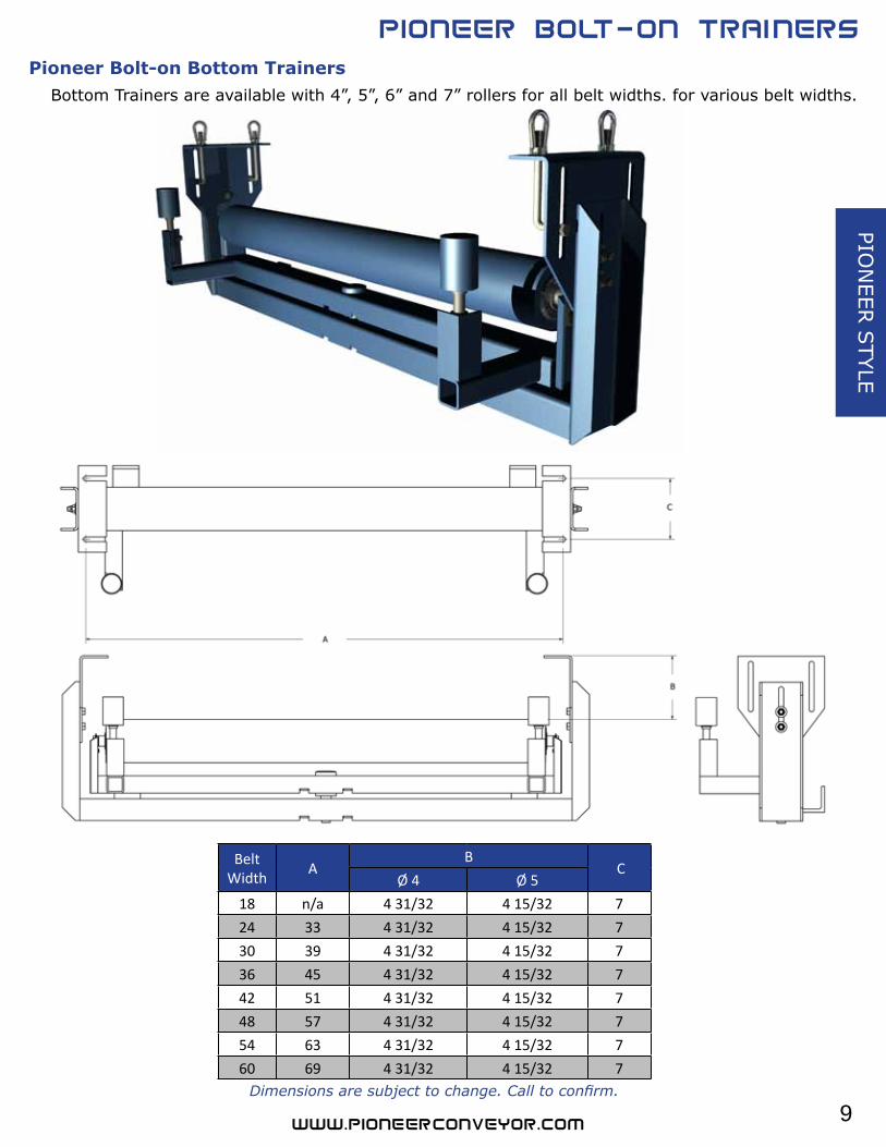
Pioneer Bolt-on Bottom TrainersBottom Trainers are available with 4”, 5”, 6” and 7” rollers for all belt widths. for various belt widths.
Belt Width A
B C
Ø 4 Ø 518 n/a 4 31/32 4 15/32 7 24 33 4 31/32 4 15/32 7 30 39 4 31/32 4 15/32 7 36 45 4 31/32 4 15/32 7 42 51 4 31/32 4 15/32 7 48 57 4 31/32 4 15/32 7 54 63 4 31/32 4 15/32 7 60 69 4 31/32 4 15/32 7
Dimensions are subject to change. Call to confirm.
10
CAT
ENARY
STY
LE
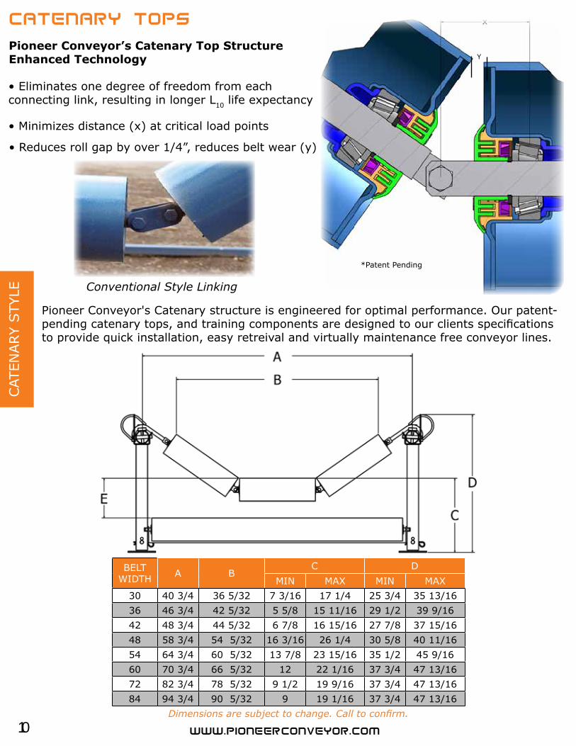
Pioneer Conveyor's Catenary structure is engineered for optimal performance. Our patent-pending catenary tops, and training components are designed to our clients specifications to provide quick installation, easy retreival and virtually maintenance free conveyor lines.
• Eliminates one degree of freedom from eachconnecting link, resulting in longer L10 life expectancy
Pioneer Conveyor’s Catenary Top Structure Enhanced Technology
Conventional Style Linking
*Patent Pending
BELT WIDTH A B
C DMIN MAX MIN MAX
30 40 3/4 36 5/32 7 3/16 17 1/4 25 3/4 35 13/1636 46 3/4 42 5/32 5 5/8 15 11/16 29 1/2 39 9/1642 48 3/4 44 5/32 6 7/8 16 15/16 27 7/8 37 15/1648 58 3/4 54 5/32 16 3/16 26 1/4 30 5/8 40 11/1654 64 3/4 60 5/32 13 7/8 23 15/16 35 1/2 45 9/1660 70 3/4 66 5/32 12 22 1/16 37 3/4 47 13/1672 82 3/4 78 5/32 9 1/2 19 9/16 37 3/4 47 13/1684 94 3/4 90 5/32 9 19 1/16 37 3/4 47 13/16
• Reduces roll gap by over 1/4”, reduces belt wear (y)
• Minimizes distance (x) at critical load points
Y
Dimensions are subject to change. Call to confirm.
11
CATEN
ARY S
TYLE
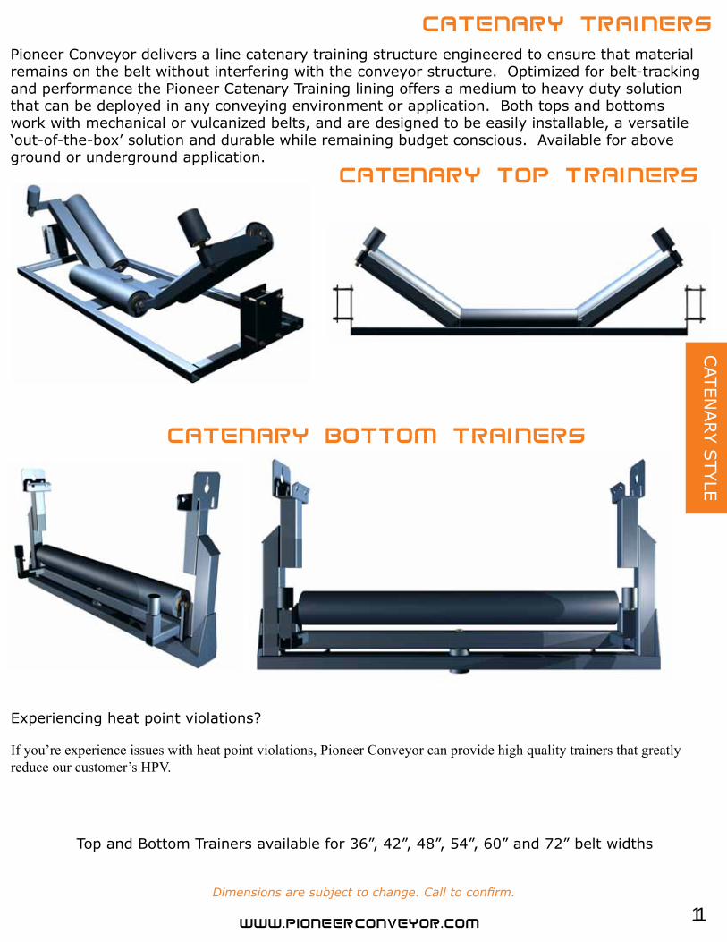
Pioneer Conveyor delivers a line catenary training structure engineered to ensure that material remains on the belt without interfering with the conveyor structure. Optimized for belt-tracking and performance the Pioneer Catenary Training lining offers a medium to heavy duty solution that can be deployed in any conveying environment or application. Both tops and bottoms work with mechanical or vulcanized belts, and are designed to be easily installable, a versatile‘out-of-the-box’ solution and durable while remaining budget conscious. Available for above ground or underground application.
Top and Bottom Trainers available for 36”, 42”, 48”, 54”, 60” and 72” belt widths
Dimensions are subject to change. Call to confirm.
Experiencing heat point violations?
If you’re experience issues with heat point violations, Pioneer Conveyor can provide high quality trainers that greatlyreduce our customer’s HPV.

12
IMPA
CT
STR
UCTU
RE
Belt Width A B C D
18 27 12 9/32 5 3/4 8 5/1624 33 13 5/8 5 3/4 8 5/1630 39 14 1/2 5 3/4 8 5/1636 45 15 15/16 5 3/4 8 5/1642 51 17 1/16 7 1/2 8 5/1648 57 18 1/4 7 1/2 8 5/1654 63 20 1/4 9 8 5/1660 69 20 1/2 9 8 5/16
Pioneer Bolt-on Slides are available in CEMA C or CEMA D specs, and also can be custom designed and manufactured to suites the needs of your mine. Available in standard belt widths: 18, 24, 30, 36, 42, 48, 54, 60, 72 and 84.
Pioneer Conveyor offers various impact structures to eliminate structure damage at any impact point in a conveyor system. Individual impact top idlers, cross belt sliders or bolt down slider beds are available for various belt sizes and applications.
Cross Belt Sliders can be deployed for a minimal maintenance impact application. Shown here as part of a Pioneer Tail Piece assembly. Available in various sizes and can be customized to meet the customers specifications.
Dimensions are subject to change. Call to confirm.
13
RETR
O-FIT
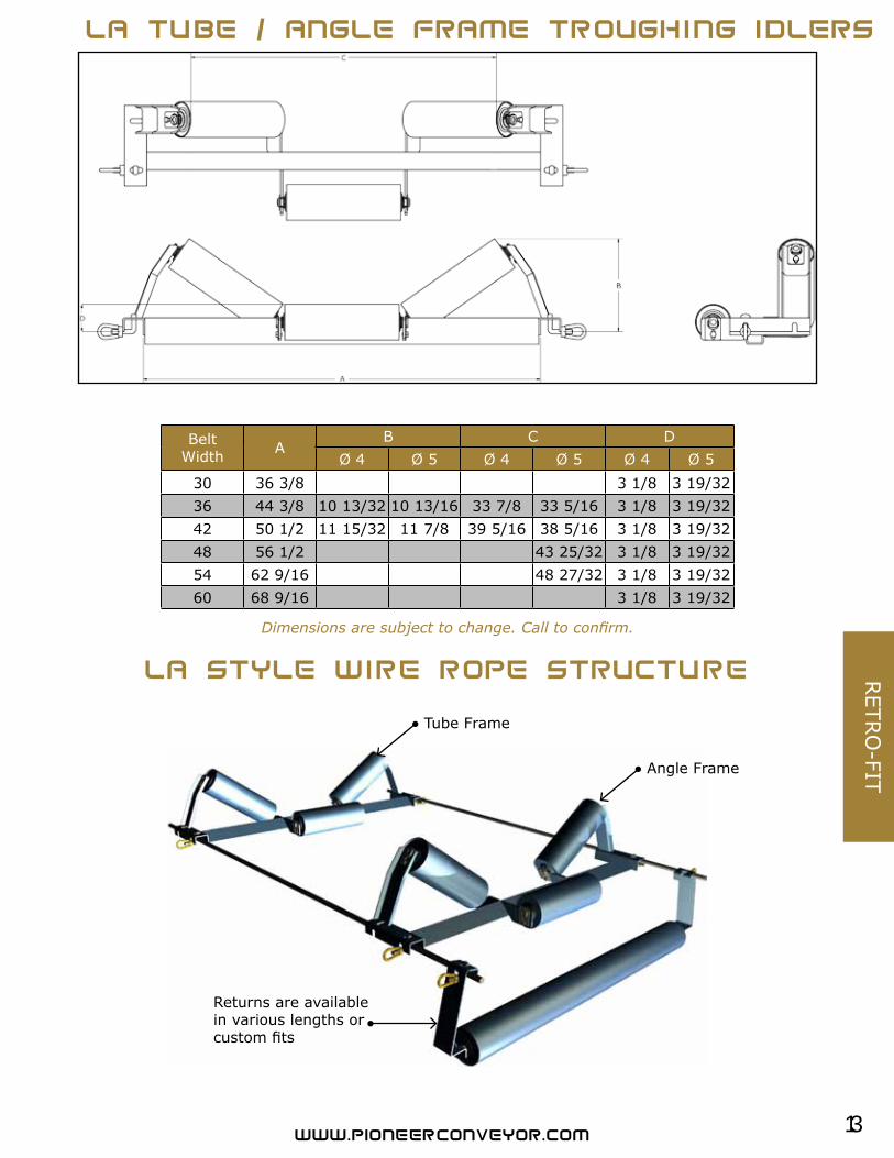
BeltWidth A
B C DØ 4 Ø 5 Ø 4 Ø 5 Ø 4 Ø 5
30 36 3/8 3 1/8 3 19/3236 44 3/8 10 13/32 10 13/16 33 7/8 33 5/16 3 1/8 3 19/3242 50 1/2 11 15/32 11 7/8 39 5/16 38 5/16 3 1/8 3 19/3248 56 1/2 43 25/32 3 1/8 3 19/3254 62 9/16 48 27/32 3 1/8 3 19/3260 68 9/16 3 1/8 3 19/32
Returns are available in various lengths or custom fits
Angle Frame
Tube Frame
Dimensions are subject to change. Call to confirm.
14
RET
RO
-FIT
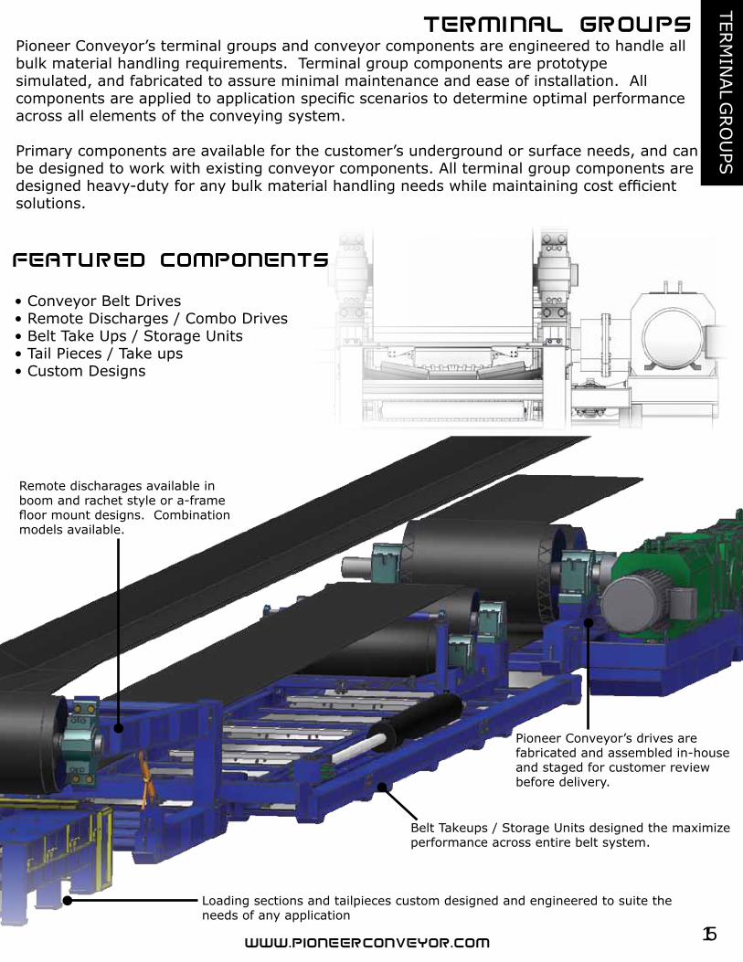
LA STYLE BIG HUB STYLE CUSTOM ADAPTERS
PIONEER CATENARY30MM TO 3/4”REPLACEMENT
DUAL-APPLICATION
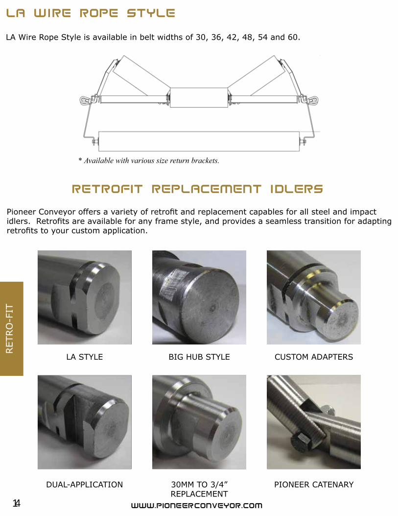
LA Wire Rope Style is available in belt widths of 30, 36, 42, 48, 54 and 60.
* Available with various size return brackets.
Pioneer Conveyor offers a variety of retrofit and replacement capables for all steel and impact idlers. Retrofits are available for any frame style, and provides a seamless transition for adapting retrofits to your custom application.
15
TERM
INAL G
RO
UPS
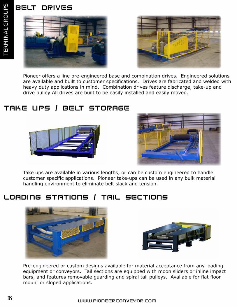
Loading sections and tailpieces custom designed and engineered to suite the needs of any application
Belt Takeups / Storage Units designed the maximize performance across entire belt system.
Remote discharages available in boom and rachet style or a-frame floor mount designs. Combination models available.
Pioneer Conveyor’s drives arefabricated and assembled in-house and staged for customer reviewbefore delivery.
Pioneer Conveyor’s terminal groups and conveyor components are engineered to handle all bulk material handling requirements. Terminal group components are prototype simulated, and fabricated to assure minimal maintenance and ease of installation. Allcomponents are applied to application specific scenarios to determine optimal performance across all elements of the conveying system.
Primary components are available for the customer’s underground or surface needs, and can be designed to work with existing conveyor components. All terminal group components are designed heavy-duty for any bulk material handling needs while maintaining cost efficient solutions.
• Conveyor Belt Drives• Remote Discharges / Combo Drives• Belt Take Ups / Storage Units• Tail Pieces / Take ups• Custom Designs
16
TERM
INAL
GRO
UPS
Pioneer offers a line pre-engineered base and combination drives. Engineered solutions are available and built to customer specifications. Drives are fabricated and welded with heavy duty applications in mind. Combination drives feature discharge, take-up and drive pulley All drives are built to be easily installed and easily moved.
Take ups are available in various lengths, or can be custom engineered to handlecustomer specific applications. Pioneer take-ups can be used in any bulk materialhandling environment to eliminate belt slack and tension.
Pre-engineered or custom designs available for material acceptance from any loadingequipment or conveyors. Tail sections are equipped with moon sliders or inline impact bars, and features removable guarding and spiral tail pulleys. Available for flat floor mount or sloped applications.
17
TURN
KEY PR
OJEC
TS
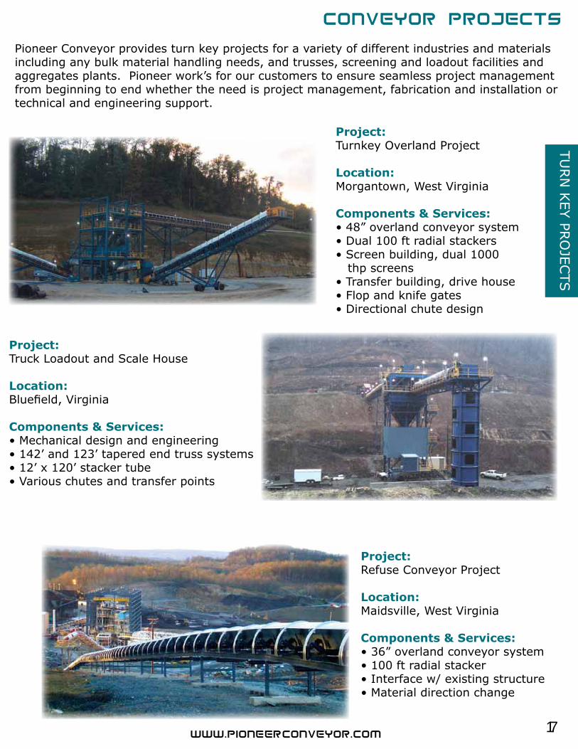
Pioneer Conveyor provides turn key projects for a variety of different industries and materialsincluding any bulk material handling needs, and trusses, screening and loadout facilities andaggregates plants. Pioneer work’s for our customers to ensure seamless project management from beginning to end whether the need is project management, fabrication and installation or technical and engineering support.
Project:Truck Loadout and Scale House
Location:Bluefield, Virginia
Components & Services:• Mechanical design and engineering• 142’ and 123’ tapered end truss systems• 12’ x 120’ stacker tube• Various chutes and transfer points
Project:Turnkey Overland Project
Location:Morgantown, West Virginia
Components & Services:• 48” overland conveyor system• Dual 100 ft radial stackers• Screen building, dual 1000 thp screens• Transfer building, drive house• Flop and knife gates• Directional chute design
Project:Refuse Conveyor Project
Location:Maidsville, West Virginia
Components & Services:• 36” overland conveyor system• 100 ft radial stacker• Interface w/ existing structure• Material direction change
18
TURN
KEY
PRO
JECTS
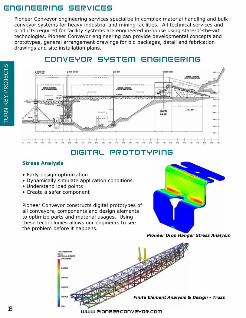
Pioneer Conveyor engineering services specialize in complex material handling and bulk conveyor systems for heavy industrial and mining facilities. All technical services and products required for facility systems are engineered in-house using state-of-the-art technologies. Pioneer Conveyor engineering can provide developmental concepts and prototypes, general arrangement drawings for bid packages, detail and fabricationdrawings and site installation plans.
Stress Analysis
• Early design optimization • Dynamically simulate application conditions• Understand load points • Create a safer component
Pioneer Conveyor constructs digital prototypes of all conveyors, components and design elements to optimize parts and material usages. Using these technologies allows our engineers to see the problem before it happens.
Pioneer Drop Hanger Stress Analysis
Finite Element Analysis & Design - Truss
19
INLIN
E STR
UCTU
RE
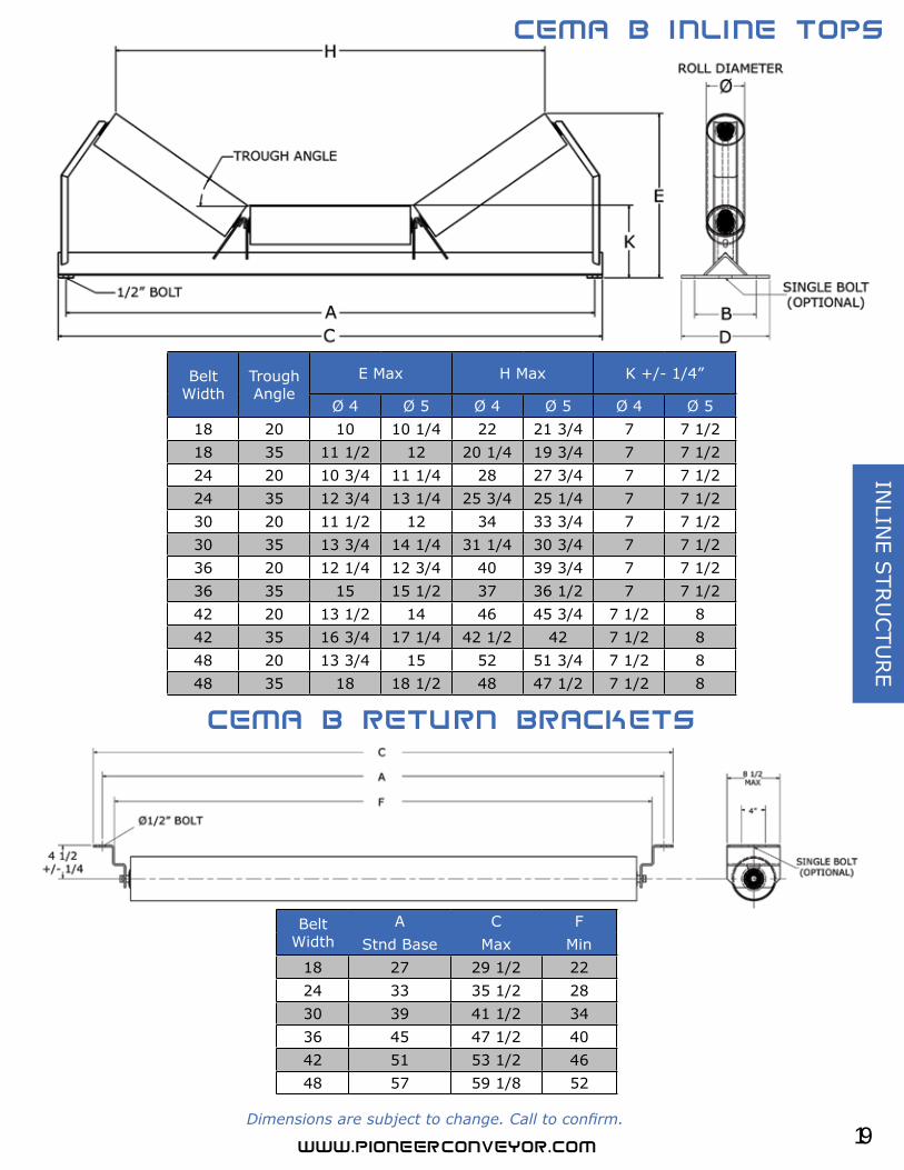
Belt Width
A C FStnd Base Max Min
18 27 29 1/2 22 24 33 35 1/2 28 30 39 41 1/2 34 36 45 47 1/2 40 42 51 53 1/2 46 48 57 59 1/8 52
Belt Width
Trough Angle
E Max H Max K +/- 1/4”
Ø 4 Ø 5 Ø 4 Ø 5 Ø 4 Ø 518 20 10 10 1/4 22 21 3/4 7 7 1/218 35 11 1/2 12 20 1/4 19 3/4 7 7 1/224 20 10 3/4 11 1/4 28 27 3/4 7 7 1/224 35 12 3/4 13 1/4 25 3/4 25 1/4 7 7 1/230 20 11 1/2 12 34 33 3/4 7 7 1/230 35 13 3/4 14 1/4 31 1/4 30 3/4 7 7 1/236 20 12 1/4 12 3/4 40 39 3/4 7 7 1/236 35 15 15 1/2 37 36 1/2 7 7 1/242 20 13 1/2 14 46 45 3/4 7 1/2 8 42 35 16 3/4 17 1/4 42 1/2 42 7 1/2 8 48 20 13 3/4 15 52 51 3/4 7 1/2 8 48 35 18 18 1/2 48 47 1/2 7 1/2 8
Dimensions are subject to change. Call to confirm.
20
INLI
NE
STR
UCTU
RE
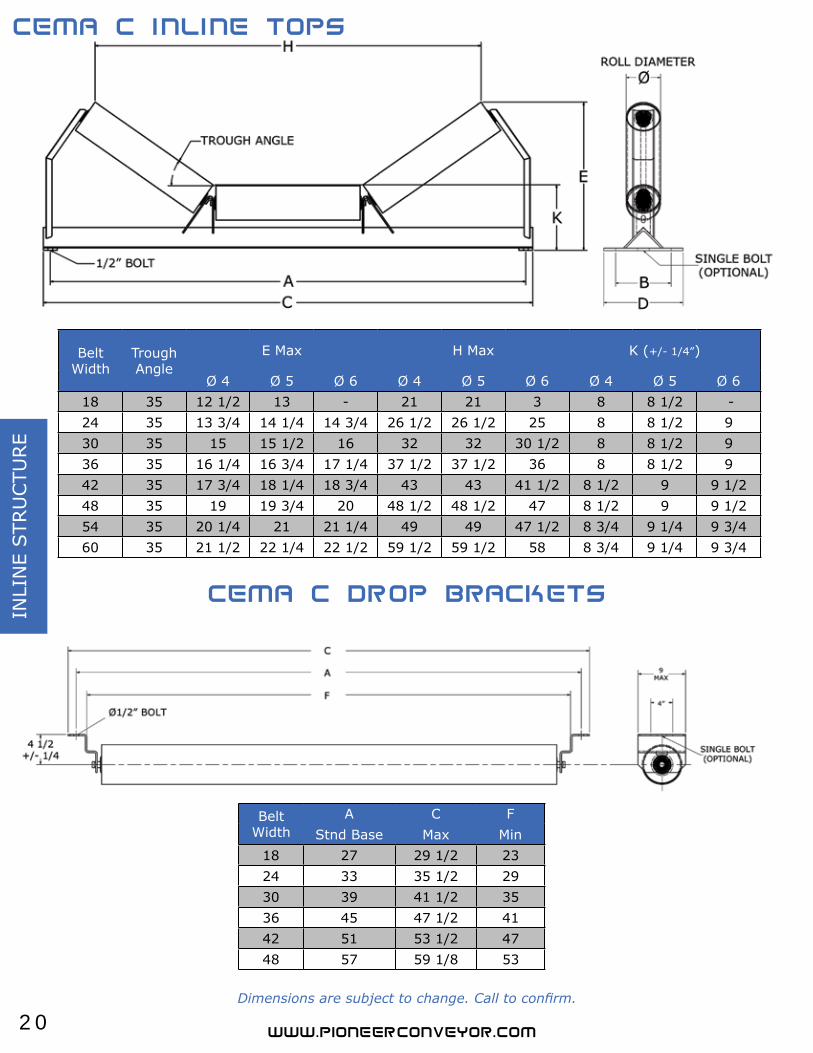
Belt Width
Trough Angle
E Max H Max K (+/- 1/4”)
Ø 4 Ø 5 Ø 6 Ø 4 Ø 5 Ø 6 Ø 4 Ø 5 Ø 618 35 12 1/2 13 - 21 21 3 8 8 1/2 -24 35 13 3/4 14 1/4 14 3/4 26 1/2 26 1/2 25 8 8 1/2 9 30 35 15 15 1/2 16 32 32 30 1/2 8 8 1/2 9 36 35 16 1/4 16 3/4 17 1/4 37 1/2 37 1/2 36 8 8 1/2 9 42 35 17 3/4 18 1/4 18 3/4 43 43 41 1/2 8 1/2 9 9 1/248 35 19 19 3/4 20 48 1/2 48 1/2 47 8 1/2 9 9 1/254 35 20 1/4 21 21 1/4 49 49 47 1/2 8 3/4 9 1/4 9 3/460 35 21 1/2 22 1/4 22 1/2 59 1/2 59 1/2 58 8 3/4 9 1/4 9 3/4
Belt Width
A C FStnd Base Max Min
18 27 29 1/2 23 24 33 35 1/2 29 30 39 41 1/2 35 36 45 47 1/2 41 42 51 53 1/2 47 48 57 59 1/8 53
Dimensions are subject to change. Call to confirm.
21
INLIN
E STR
UCTU
RE
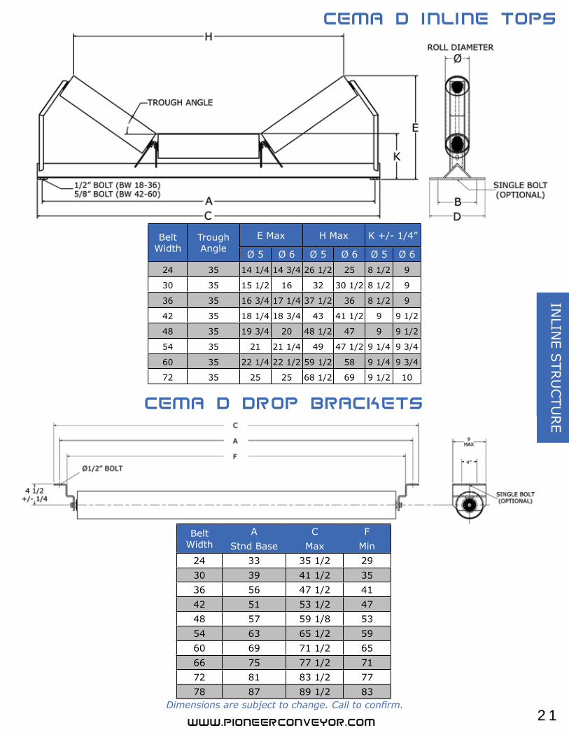
Belt Width
A C FStnd Base Max Min
24 33 35 1/2 29 30 39 41 1/2 35 36 56 47 1/2 41 42 51 53 1/2 47 48 57 59 1/8 53 54 63 65 1/2 59 60 69 71 1/2 65 66 75 77 1/2 71 72 81 83 1/2 77 78 87 89 1/2 83
Belt Width
Trough Angle
E Max H Max K +/- 1/4”
Ø 5 Ø 6 Ø 5 Ø 6 Ø 5 Ø 624 35 14 1/4 14 3/4 26 1/2 25 8 1/2 9
30 35 15 1/2 16 32 30 1/2 8 1/2 9
36 35 16 3/4 17 1/4 37 1/2 36 8 1/2 9
42 35 18 1/4 18 3/4 43 41 1/2 9 9 1/2
48 35 19 3/4 20 48 1/2 47 9 9 1/2
54 35 21 21 1/4 49 47 1/2 9 1/4 9 3/4
60 35 22 1/4 22 1/2 59 1/2 58 9 1/4 9 3/4
72 35 25 25 68 1/2 69 9 1/2 10
Dimensions are subject to change. Call to confirm.
22
INLI
NE
STR
UCTU
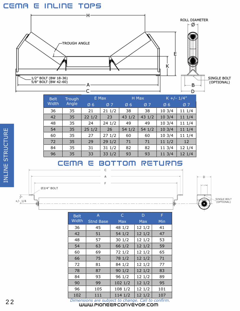
RE
Belt Width
A C D FStnd Base Max Max Min
36 45 48 1/2 12 1/2 41 42 51 54 1/2 12 1/2 47 48 57 30 1/2 12 1/2 53 54 63 66 1/2 12 1/2 59 60 69 72 1/2 12 1/2 65 66 75 78 1/2 12 1/2 71 72 81 84 1/2 12 1/2 77 78 87 90 1/2 12 1/2 83 84 93 96 1/2 12 1/2 89 90 99 102 1/2 12 1/2 95 96 105 108 1/2 12 1/2 101 102 111 114 1/2 12 1/2 107
Belt Width
Trough Angle
E Max H Max K +/- 1/4”Ø 6 Ø 7 Ø 6 Ø 7 Ø 6 Ø 7
36 35 21 21 1/2 38 38 10 3/4 11 1/4 42 35 22 1/2 23 43 1/2 43 1/2 10 3/4 11 1/4 48 35 24 24 1/2 49 49 10 3/4 11 1/4 54 35 25 1/2 26 54 1/2 54 1/2 10 3/4 11 1/4 60 35 27 27 1/2 60 60 10 3/4 11 1/4 72 35 29 29 1/2 71 71 11 1/2 12 84 35 31 31 1/2 82 82 11 3/4 12 1/4 96 35 33 33 1/2 93 93 11 3/4 12 1/4
Dimensions are subject to change. Call to confirm.
23
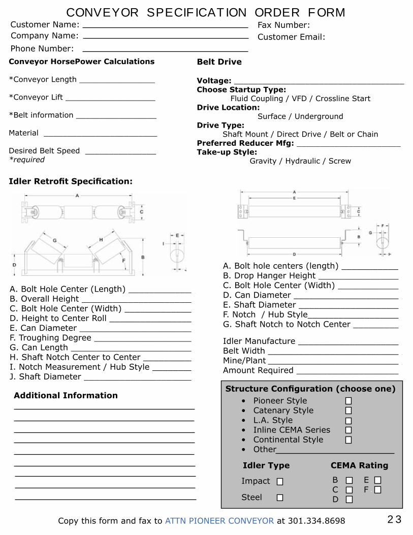
CONVEYOR SPECIFICATION ORDER FORMCustomer Name:Company Name:Phone Number:
Fax Number:Customer Email:
Structure Configuration (choose one)• Pioneer Style• Catenary Style• L.A. Style• Inline CEMA Series• Continental Style• Other
A. Bolt Hole Center (Length) _____________B. Overall Height ______________________C. Bolt Hole Center (Width) _____________D. Height to Center Roll ________________E. Can Diameter ______________________F. Troughing Degree ___________________G. Can Length ________________________H. Shaft Notch Center to Center __________I. Notch Measurement / Hub Style ________J. Shaft Diameter _____________________
Idler Manufacture ____________________Belt Width __________________________Mine/Plant __________________________Amount Required ____________________
A. Bolt hole centers (length) ___________ B. Drop Hanger Height ________________ C. Bolt Hole Center (Width) ____________ D. Can Diameter _____________________ E. Shaft Diameter ____________________F. Notch / Hub Style__________________G. Shaft Notch to Notch Center _________
Impact
Steel
CEMA Rating
BCD
EF
Conveyor HorsePower Calculations
*Conveyor Length ________________
*Conveyor Lift ___________________
*Belt information _________________
Material ________________________
Desired Belt Speed _______________*required
Additional Information
Copy this form and fax to ATTN PIONEER CONVEYOR at 301.334.8698
Idler Type
Belt Drive
Voltage: ____________________________________Choose Startup Type:
Fluid Coupling / VFD / Crossline StartDrive Location:
Surface / UndergroundDrive Type:
Shaft Mount / Direct Drive / Belt or ChainPreferred Reducer Mfg: ______________________Take-up Style:
Gravity / Hydraulic / Screw
Idler Retrofit Specification:
Phone: 301.334.8186 Fax: 301.334.8698
E-Mail: [email protected]
32 Enterprise DriveP.O. BOX 2446 Mtn Lake Park, MD 21550
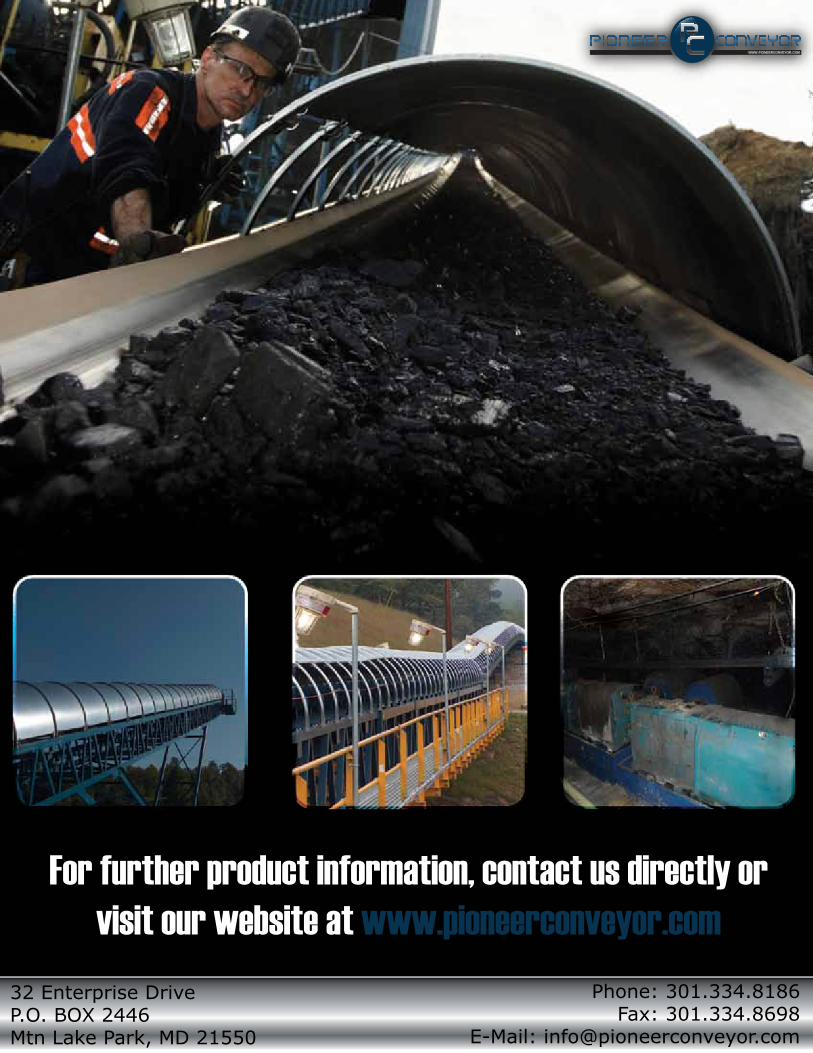
For further product information, contact us directly or visit our website at www.pioneerconveyor.com