Embed Size (px)
Citation preview
1
“Advanced Design Considerations Required for Overland Aggregate Conveyors” www.overlandconveyor.com
Mark A. Alspaugh
Principal Systems Engineer Overland Conveyor Co Inc
Grzegorz Dewicki
Manager, Advanced Technology Overland Conveyor Co Inc
Abstract As belt conveyors get longer and conveyor systems get more complex, it is important for conveyor engineers to understand and utilize advanced design principals required to insure a robust, reliable and cost effective material handling system. Most of these advanced considerations are not covered by traditional conveyor design methods such as CEMA (Conveyor Equipment Manufacturers Association). These include (1) the principal of analyzing conveyors as flexible systems rather than rigid bodies (Dynamic Analysis), (2) non-traditional route configurations including horizontal curves and vertical lifts, (3) mass flow simulations (using Discrete Element Methods) of loading and unloading. This paper will review current state-of-the-art analysis and simulation techniques. The Belt Conveyor System By definition, a system is a set of interrelated components working together toward some common purpose. The properties and behavior of each component of the system has an affect on the performance of the whole system and the performance of each component of the system depends on the properties and behavior of the system as a whole. Although we tend to think of belt conveyors as fairly simple machines, they actual fall into the category of a complex system and the interdependencies of sub-systems and components are important to understand in order to insure a reliable and dependable machine. In general, the complexity of all systems desired by society is increasing as we see when we buy a new car or washing machine or most anything else. Belt conveyors are no different. As new technologies become available, the pull of "want" is augmented by the push to incorporate these new capabilities into both new and existing systems. In addition, the desire for bigger and cheaper machines produces an ever-changing set of requirements. Twenty years ago, a 42” wide conveyor 1000 ft long carrying 1000 tph of aggregate might have been considered “big”. Today, our industry will readily accept the challenge of
designing conveyors up to 10 miles long, 72” wide, with capacities of over 20,000 tph. Sometimes, the identification of "true need" and the elicitation of "real requirements" are in themselves, a technological challenge. As such, we have to be very careful not to adopt the attitude of "design now and fix later", with a negative impact on the value of complex systems to intended users. Today, most large-scale projects require the combined input of specialists representing a wide variety of engineering disciplines. Successful conveyor engineering requires a combination of these technical specialties and expertise. However, technical specialists not only require the basic knowledge of individual specialty fields, but also require knowledge of the context of the system being built (i.e. its purpose, use and some knowledge of all the other components and specialties). This requirement has led to a new approach to design.
Figure 1 - Overland Conveyor System at an Aggregate facility.

2
Systems Engineering This new field, called system engineering actually began in the late 1950s with large-scale military and aerospace projects. Since then, the method has been adopted by automakers and many high-tech manufacturers. Examples of system engineering in motion are plentiful. No matter where you look, you’ll find component integration and function consolidation. Even engineering schools are getting into it, offering courses upon which the feats of 21st century engineering are likely to be built. According to the International Council on Systems Engineering, it is “an interdisciplinary approach and means to enable the realization of successful systems”. In other words, it’s a way to design and build complex machines, which actual do what they’re supposed to do for as long as they’re supposed to do it. System engineering focuses on defining needs and functions early in the development cycle. It entails documenting all requirements at the start, then generating and validating the design with the entire machine life cycle in mind. Although it involves additional work, the benefits of system engineering make it worthwhile. An important part of the systems engineering process
is testing and optimization. However, with very large machines such as belt conveyors, only components can be tested. It is normally impossible to physical assemble and test a complete system which extends for miles. Therefore, testing typically occurs after the machine is built and ready to be handed over to production. At this point, it is very difficult and expensive to make significant changes. For this reason, a belt conveyor engineer relies very heavily on numerical modeling and mathematical tools to function as the system simulator. Computer simulation is the discipline of designing an actual or theoretical model, executing the model on a computer, evaluating the results and gaining knowledge of the system characteristics and performance. The traditional methods of analyzing and modeling belt conveyors in North America for the last 40 years has followed standards laid out in “Belt Conveyors for Bulk Materials”, 5th Edition published by CEMA; Conveyor Equipment Manufacturers Association. (See Appendix A for further narrative regarding this reference). Although this standard has served many industries including aggregates very well over the years, it has self-admitted limitations and is not necessarily well suited to large system requirements we find today. As such, several advanced analytical
Figure 2- Systems Engineering Process
Figure 2- Systems Design Influence Figure 3- Cost of Change
3
techniques have been developed for long overland conveyors. The remainder of this paper will demonstrate three such simulation techniques used today.
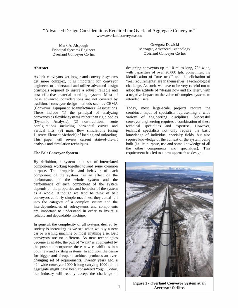
Dynamic Analysis CEMA design methods for stopping and starting a conveyor treat the system as a rigid body. CEMA realizes the potential problem with this approach in a statement on page 140 of the 5th Edition of BELT CONVEYORS FOR BULK MATERIALS. “No further attempt will be made to justify the [rigid body] assumption. However, the belt conveyor designer should be aware that, for conveyor systems with very long center belts, stretch considerations should not be overlooked”. However there is no methodology given which considers belt stretch considerations. When long conveyors are designed with these static models only, potential troubles exist such as excessive belt tensions and structural loads, excessive take-up travel, drive slippage, belt sag and slippage and component failures. When dealing with long conveyors, it is important to treat the conveyor as a system of interacting flexible components rather than a single rigid body. The specific attributes of and relationships between the drives, control software, belt and the take-up device are definitely not static in nature. As system engineers, we attempt to define these relationships as well as the performance characteristics of each component. We build mass and stiffness matrices, apply the appropriate boundary conditions and solve simultaneously with a time-based finite element methodology. Although this methodology was first published over 20 years ago, it has not been used widely due to the complexity of the analysis. However, recent advances in computer technology have advanced its use. Today, this technology has proven to be much more effective in simulating actual conveyor characteristics during the most critical operating conditions of starting and stopping. For the purpose of this paper, a simplified explanation of the dynamic principals is shown. Figure 4, shows a simple 2-pulley conveyor while running at steady state. The belt velocity everywhere is nearly the same and the spring extensions (belt stretch) remain constant and unchanged. The difference between the tight side (T1) and slack side (T2) of the drive pulley is the torque applied by the drive. The tension in the springs between the masses is determined by the stiffness of the belt and its extension.
DriveTorque
Belt Tension
Belt Tension
T1
T2
Time = t
Figure 4 Steady State Running- Mass Spring Representation
Figure 5, shows the system a short time after the drive has been turned off and the torque is removed. The result is a wave of decreased tension traveling down the carry side and a wave of increased tension traveling down the return side. These are often referred to as ‘tension’ and ‘compression’ waves, which propagate around the conveyor and eventually, dampen out.
Belt Tension
Belt Tension
Time = t + td
T1
T2
Figure 5 Mass spring Representation of Coasting to Stop
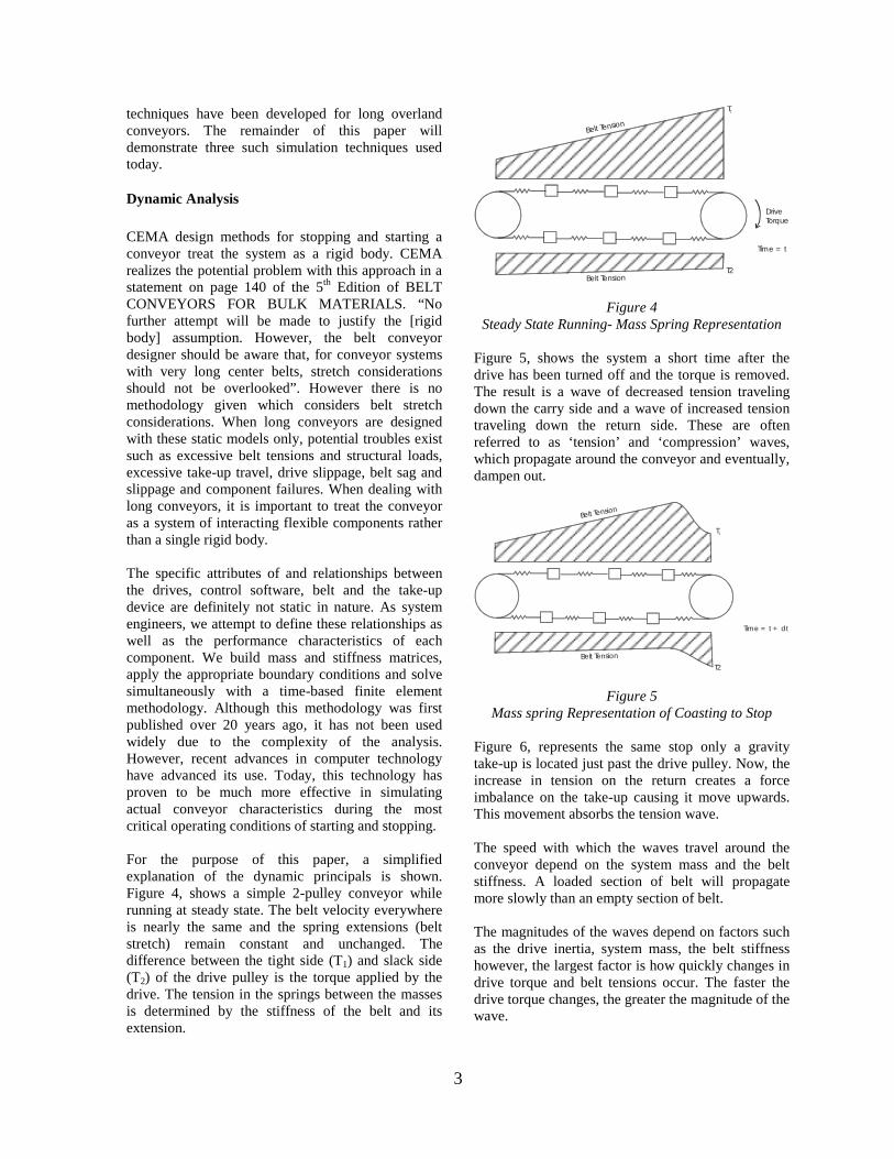
Figure 6, represents the same stop only a gravity take-up is located just past the drive pulley. Now, the increase in tension on the return creates a force imbalance on the take-up causing it move upwards. This movement absorbs the tension wave. The speed with which the waves travel around the conveyor depend on the system mass and the belt stiffness. A loaded section of belt will propagate more slowly than an empty section of belt. The magnitudes of the waves depend on factors such as the drive inertia, system mass, the belt stiffness however, the largest factor is how quickly changes in drive torque and belt tensions occur. The faster the drive torque changes, the greater the magnitude of the wave.
4
Belt Tension
Time = t + td
T2
T1
Figure 6 Mass Spring Representation of Stopping with a
Gravity Take-up
The exact same dynamic action occurs during starting however the changes are due to increases in drive pulley torque rather than decreases. Tracking the interaction of the waves is what is commonly referred to as dynamic analysis. Although dynamic analysis is commonly used today on very long and expensive overland conveyor using steel cord belt, it is not commonly used on smaller conveyor. However, an argument can be made that it is just as important to understand the dynamics of smaller conveyors with fabric belts as the low stiffness of fabric belts can magnify dynamic problems. This is even more important on conveyors with drive types that accelerate conveyors to full speed very quickly. This is often the cause of problems such as:
1- Short belt splice life 2- Failed pulleys 3- Drive slip 4- Belt sag and spillage 5- Liftoff in concave curves
Horizontal Curves Selecting the path of an overland conveyor can have a significant effect on the initial capital cost of the project and can have an effect on the long term operating and maintenance costs. Maintenance costs are often directly related to the number of transfer points along the conveyance route as belting wear as well as cleanup costs are generally related to transfer areas.
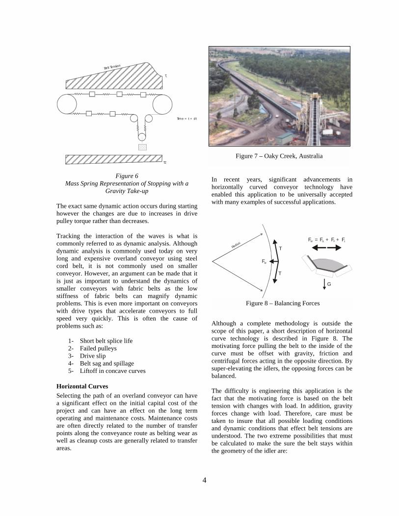
In recent years, significant advancements in horizontally curved conveyor technology have enabled this application to be universally accepted with many examples of successful applications.
Although a complete methodology is outside the scope of this paper, a short description of horizontal curve technology is described in Figure 8. The motivating force pulling the belt to the inside of the curve must be offset with gravity, friction and centrifugal forces acting in the opposite direction. By super-elevating the idlers, the opposing forces can be balanced. The difficulty is engineering this application is the fact that the motivating force is based on the belt tension with changes with load. In addition, gravity forces change with load. Therefore, care must be taken to insure that all possible loading conditions and dynamic conditions that effect belt tensions are understood. The two extreme possibilities that must be calculated to make the sure the belt stays within the geometry of the idler are:
Figure 7 – Oaky Creek, Australia
Figure 8 – Balancing Forces
Radius
T
T
FM
F = F + F + FM G F c
G
5
1- Lowest belt tension / Fully Loaded Belt 2- Highest belt tension / Empty Belt
Discrete Element Modeling of Mass Flow What is Discrete Element Methods/Modeling (DEM)? Discrete element methods are a family of numerical modeling techniques designed to solve problems in engineering and applied science that exhibit gross discontinuous behavior, see references [3,4]. It should be noted that conventional continuum based computer-modeling methods such as finite element or finite difference procedures are not capable alone of simulating and modeling problems dominated by discontinuum behavior. There are a large number of engineering examples dominated by discontinuum behavior including and not limited to loading and discharge areas of the conveyor system, the transfer point. Some of the other areas where DEM can be used in are mineral processing and storage, like milling, tumbling, screening, hoppers, feeders, crushers, mixers, even the material on conveyor system and many more. A transfer point is the location on a conveyor where the material is loaded or unloaded. A typical transfer point is composed of metal chutes that guide the flow of material. In most applications, problematic material flow conditions occur because the design of transfer points often rely on rule-of-thumb techniques, engineering and years of experience. This often lacks one basic component of analysis and simulation, which leads to arcane solutions that require field modification and costly maintenance. The design of a transfer point will greatly affect the life of its components, maintenance costs and safety and yet it is always left to the end and considered as an after taught. Chute and other loading equipment is heavily influence by conditions such as the capacity, size, vertical drop, characteristics of the material handled, speed and inclination of the belt and whether it is loaded at one or several locations. An ideal transfer point would be designed to take into account the following: !" Center loading of the material !" Loading of material at a uniform rate !" Loading of material in the direction of belt travel
(receiving conveyor) !" Loading of material at the same speed as the belt
is moving (receiving conveyor) !" After the belt is fully troughed !" Loading of material with minimum impact
At the same time, the transfer point has to prevent: !" Plugging !" Chute wear and belt wear !" The creation of dust !" Material spillage Ideal transfer point chutes are very difficult to achieve by rule-of-thumb engineering and techniques, as most chute geometry and conditions are unique and cannot be tested at full-scale or optimized in a laboratory or workshop. As such, most users unfortunate live with the problems, which lead to high maintenance costs and retrofits. But not to worry there are options. The discrete element method (DEM) has been shown as an excellent computational tool for simulating the material flow in transfer stations. One engineering design tool, which now leads the way in bulk material handling analysis of transfer points, is Chute AnalystTM, a software application that integrates the DEM and Computer Aided Design (CAD). The results from a DEM model provide a detailed evolution of the particles motion, interaction forces and stresses over the duration of the analysis. These features make the DEM a very powerful tool for analyzing bulk material-handling problems as it explicitly models bulk material flow and its effects on the transfer and chute structural elements. In simple terms, DEM explicitly models the dynamic motion and mechanical interactions of each body or particle in the physical problem throughout a simulation or time, and provides a detailed description of the velocities, positions, and force acting on each body or particle at a discrete point in time during the analysis. This new integrated DEM/CAD technology is a great tool in the field of bulk material handling and specifically in the analysis and design of belt-conveyor transfers. 3-D visualizations of the modeling results provide an overall feel of the flow behavior in the chute. Wear profile, moment arm, and lateral force diagrams provide the engineer with a definable means of improving transfer station design. Bulk material transfer modeling is used to but not limited to just; (1)- optimizes material flow, (2)- minimizes abrasion to the belt and chute, and (3)- minimizes dust and material degradation. The typical process that a designer and/or engineer performs to retrofit an old or design a new transfer points are, see references [5]:
6
!" Render accurate 3-D CAD representation of old transfer or new transfer
!" Identify chute geometry restrictions and manufacturing limitations
!" Identify project goals (i.e. dust emissions, flow restrictions, etc)
!" Identify material properties and develop representative particle description
!" Make design changes to chute geometry with CAD
!" Simulate performance using Chute Analyst TM
!" Evaluate simulation results !" Detail Design !" Manufacture !" Installation
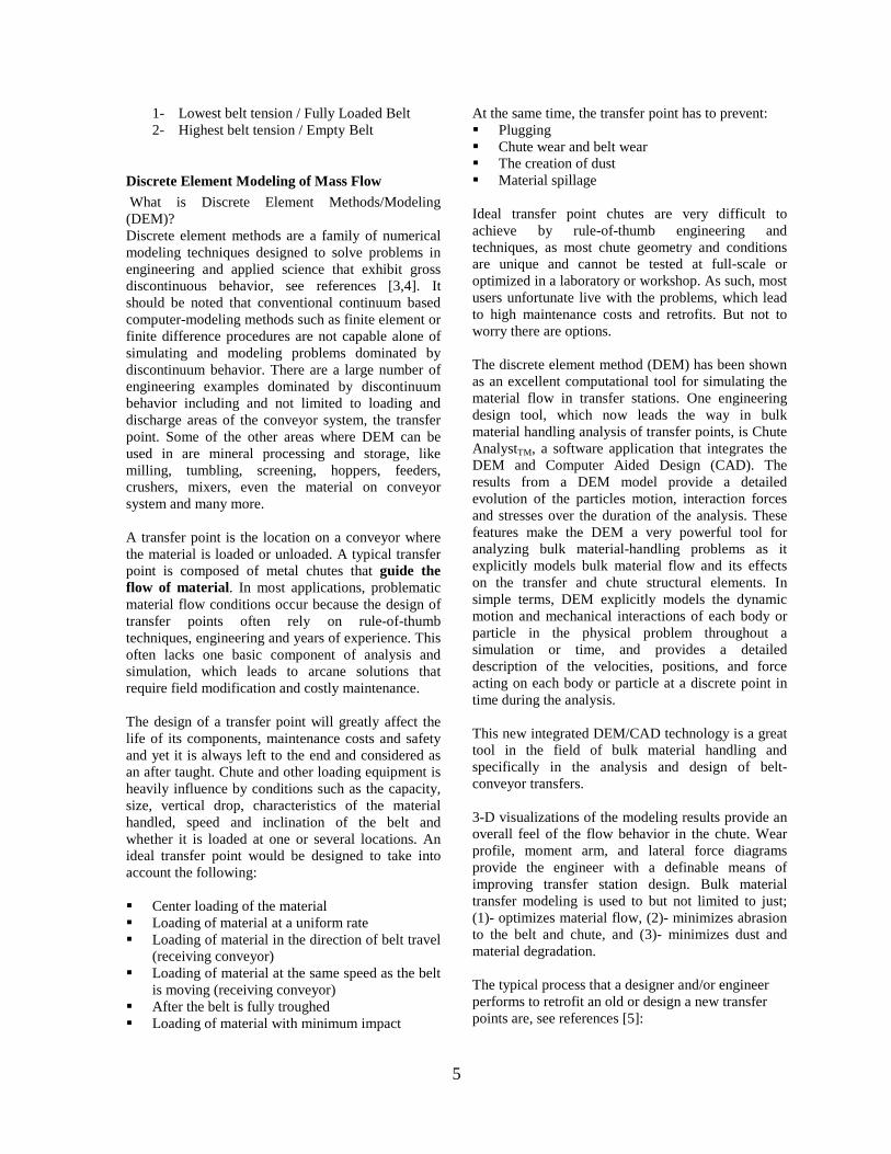
To illustrate this approach and the DEM technology at this time we would like to look at one of the projects that we have worked on specifically the Atlanta Airport Expansion Project. The Atlanta Airport Project primarily dealt with moving of fill material from the surrounding area quarries to the Atlanta Airport via a long and complicated overland conveyor system. This is not only a good example of the number of transfer points needed but also of the over all scope of the project and the shear number of companies involved in the system design concept. But for this part we will only concentrate on the transfer points and their analysis. This was a very fast pace project with very
aggressive dead lines and we had to use all of our design criteria. As there was no existing transfer points at the site we had to first come up with what is it that we are trying to achieve here and how do we go about it. In order to do this we pushed the first part, render accurate 3-D CAD representation of the new/old transfer, of our criteria down the line and started on the next two steps:
!" Identify chute geometry restrictions and manufacturing limitations
!" Identify project goals (i.e. dust emissions, flow restrictions, etc)
The chute geometry was restricted primarily by the conveyor system relationships, travel path, profile speed and capacity. The other major restriction on the geometry of the chute was the very aggressive dead line, which meant that the chutes had to be easy to manufacture and easy to install. The other major factor of the overland conveyor system was that there were 48 and 72 inch wide belts in the overland system and 60 inch wide belts at different speeds in the loading and discharge areas. The project goals were very broad but one of the main goals was to have chutes that would accommodate a very abrasive material of rock and clay, soil and anything else that might be conveyed. Further more, the tonnage rates for the material could vary on each transfer in some cases it could be 1500tph and in other cases it could be 7000tph.
Figure 9 - Atlanta Airport Expansion Project - Overland Conveyor System.
Transfer Points in the system.
Future Change of the system
Iterate
7
At the same time, we had to identify material properties and develop representative particle description for clay, soil and combination of rock. This brought us to our next step of identify material properties and develop representative particle description. The material was to be a minimum of 25% crushed rock and the other 75% was to be of some kind of soil, clay and what ever the scalping and crushing plants would produce. This over all size of the rock was to be 12 inch minus but its contents in the over all material could be more than 25%. Basically, we came up with the worst case scenarios that would cause the most problems and started on the material properties. After all of this we could now return to the step one of our criteria, creating a 3-D CAD representation of the new transfers. At this point, it was decided that we needed to look at creating a chute geometry that could be used in all of the transfer point or at least have a number of components in common, a some what of a universal chute. Based on that the geometry that might best satisfies our conveyor system criteria, easy of manufacturing, installation and the material flow was a rock box/slide type of geometry shown in the figure below.
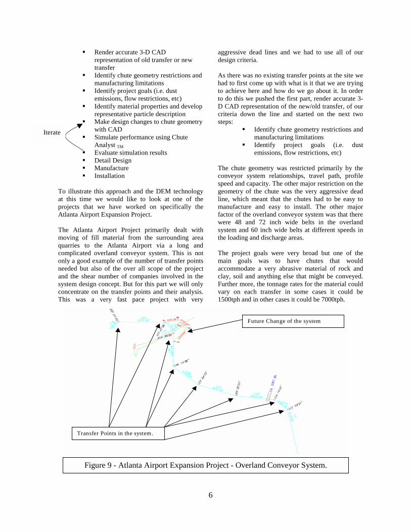
Head chute rockbox.
Slide, lower section.
Figure 10 - 72-inch wide belt conveyor system transfer point.
This type of geometry had some advantages and disadvantages. In this case the advantage being that the head chute rock box will absorb most of the direct impact of the high wear rock and confine the material into one location and redirect it vertically onto a collector, a slide in this case. The disadvantage of the head chute is that it has to bring the flow of material to a complete stop before it is redirected. The advantage of the slide is that it can collect the material from the rock box in the head chute and redirect it in any direction. The biggest disadvantage of the slide is that it would have direct as well as sliding wear on it do to the material vertical impact as it flowed from the head chute rock box.
Figure 11 - 48-inch wide belt conveyor system
transfer point. The over all advantage of this geometry was that we could apply most of this chute geometry in most of the transfer locations. Eight transfer points in the original system and four new once as the system is changed in the later stages of the operation. In addition, there were to be four additional transfer points, which would act as the loading points for the overland system and they could be used to load the 72 and 48 inch wide belts at few different locations. As for the discharge there were to be three splitter chutes that would remove a portion of the material at different locations and deliver that material through another conveyor to a truck loading station. Over all there was a great deal of complexity to consider and each transfer point had to have a number of case scenarios and iterations of analysis.
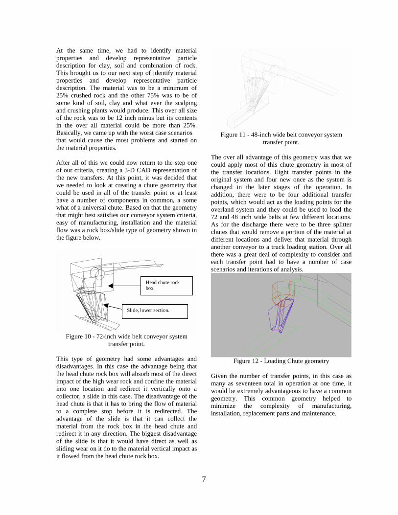
Figure 12 - Loading Chute geometry
Given the number of transfer points, in this case as many as seventeen total in operation at one time, it would be extremely advantageous to have a common geometry. This common geometry helped to minimize the complexity of manufacturing, installation, replacement parts and maintenance.

8
Figure 13 - Tripper/Splitter Chute, discharge of
material location. In this next step we had to model a range of geometry configurations in order to make sure that at first the chute selected geometry did perform well in the worst case scenarios and second that it would work well in all of the other possible conveyor to conveyor relationships (as shown in Figure 9). Some of the analysis can be see here in the next few of the figures showing the material flow through the different transfer point configurations.
Figure 14 – 72-inch wide belt conveyor system, analysis.
Figure 15 – 48-inch wide belt conveyor system,
analysis.
Figure 16 - Loading chute, onto the overland system,
analysis.
Figure 17 - Tripper/splitter discharge area of the
overland conveyor system. As it can be seen from the analysis the material flow over all was quiet good and the behavior of the transfer points was well establish prior to the installation and operation. Based on these analysis and a number of variations of them we could go through a wide range of material properties, chute geometry, conveyor to conveyor relationships and a number of load and speed scenarios with the help of DEM technology and in our case is Chute AnalystTM. This was by doing the analysis and simulations of the we could most effectively manage the time and design engineering to a minimum and meet the dead lines set in the project with the outmost confidence in our transfer points. After the analysis were complete came the part of detail engineering and manufacturing of the transfer points. The transfer points and the splitters/trippers in the overland conveyor system were manufactured by Continental Conveyor and Equipment Company, while those for loading the overland conveyor system were done by Astec Industries. The following shows just couple of the general arrangement drawings that came out of the analysis

9
geometry as to give you an idea of what the chute looked like on paper.
Figure 18 - 72inch wide belt conveyor system GA
drawing.
Figure 19 – 48-inch wide belt conveyor system GA
drawing. The final phase of the project was the installation and operation of the new conveyor system with the transfer points. The next few figures will show the transfer points geometry as they were installed with some of the material.
Figure 20 - Conveyor 6 to 7, 72-inch wide belt conveyor system, transfer point as it was being
installed.
Figure 21 - Conveyor 5 to 6, 72-inch wide belt conveyor system, transfer point as it was being
installed.
Figure 22 - Material flowing through one of the
overland conveyor system transfer points.
Figure 23 – Material on the receiving conveyor coming right out of one of the transfer stations.
10
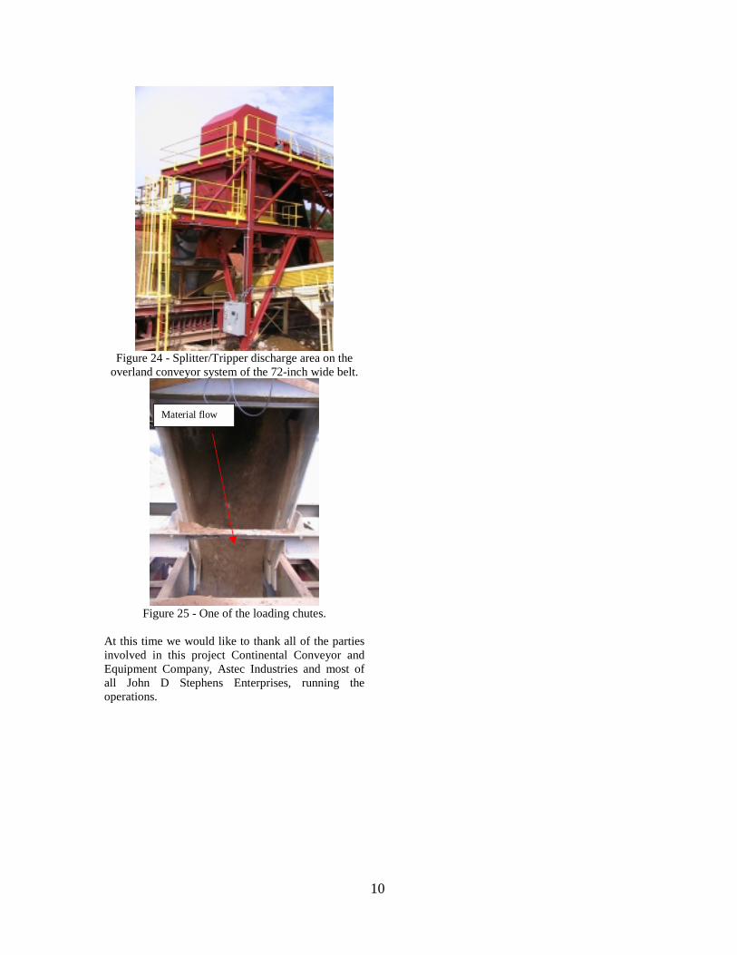
Figure 24 - Splitter/Tripper discharge area on the
overland conveyor system of the 72-inch wide belt.
Material flow
Figure 25 - One of the loading chutes.
At this time we would like to thank all of the parties involved in this project Continental Conveyor and Equipment Company, Astec Industries and most of all John D Stephens Enterprises, running the operations.
11
Appendix A
"Belt Conveyors for Bulk Materials", 5th Edition Conveyor Equipment Manufacturers Association
As to quote CEMA from their introduction: "Over the years since the first edition of this book was published, belt conveying as a means of handling bulk materials has been greatly advanced and has assumed dominance in industry. The increased dependence of industry on belt conveyors is due primarily to the fact that they have had EVERYTHING GOING FOR THEM." What is that everything that conveyor systems have going for them? (Conveying a variety of material, wide range of capacities, adaptability to path travel - steep angle conveying, loading discharging and stocking capabilities, process functions, reliability and availability, environmental advantages, safety, low labor costs, low power cost, low maintenance cost, long-distance transportation) Low labor and energy requirements are fundamental with belt conveyors as compared with other means of transportation. The only limit they have is that you can’t easily change the loading and discharge point locations. But there are such conveyor systems as grasshoppers that are shorter in nature that give you some flexibility of changing the loading and discharge locations and extending you conveyor system. Relatively long-distance conveyor systems are being used extensively because they combine important benefits like reliability, safety and low cost per ton of material transported. Belt conveyors operate continuously around the clock and around the calendar when required without loss of time for loading and unloading or empty return trips. Cost of operations per tonnage reduce with larger systems and larger tonnage handled. This last factor is starting to govern a great deal of new and future designs as end users are pushed by the bottom lines of their financial statements. Belt conveyor and equipment manufactures have consistently anticipated the needs of industry with improvements in designs and with components that have exceeded all known requirements. Again we can quote CEMA, "The technical information contained in this book is generally conservative in nature. Variations in specific application requirements or extreme service requirements should be addressed by member company engineering personnel whose depth of experience exceeds that covered in this text."
(CEMA, fifth edition, "Belt Conveyors for Bulk Materials") It might be said here that we have to start looking outside of CEMA to the engineers to come up with new tools and techniques to analyze and simulate the conveyor systems and not rely on just the rule-of-thumb past engineering experience as they do not directly scale up as the conveyor systems get larger and larger. It is also in this preliminary design part that if you have to spend time and money to design the system you do and not later on repairs, retro fits and maintenance by a magnitude of 100 again because it was not designed right. Many design methods and technical issues are outside the scope of the CEMA manual. The CEMA design criteria are somewhat conservative and are based on many field trials over a wide range of operating conditions for an average size conveyor but who now a day uses an average size conveyor. Advance technical design methods are often required for high energy, high-tension conveyors having some of the following condition as mentioned by CEMA:
• Length over 3,000 ft - distances between mining and operations continue to get longer
• Horizontal curves - to have a freedom of travel one has to have horizontal curves with concave and convex curves
• Head and Tail driven - many of the systems now a day have very complex control systems
• High lift - • Large decline with breaking - • Undulating geometrics -
The major things to consider when it comes to conveyor systems might be, as mentioned by CEMA: Conveyor Arrangements - travel path, profile, - Conveyor systems can be arranged to follow an infinite number of profiles or paths of travel. Among these are conveyors, which are horizontal, incline, or decline, or with additions of convex and concave curves and any combinations of these. In addition to

12
the profile are a numerous arrangements for loading to and discharging from the conveyors. Basics and general information found in CEMA: Chapter 3- Characteristics and Conveyability of bulk materials Chapter 4- Capacities, Belt widths, and speed Chapter 5- Belt Conveyor Idlers Chapter 6- Belt Tension, Power, and drive engineering
"Belt tension can be determined based on these calculations of horsepower. This method is suitable for use in designing simple, straight line, horizontal, or incline conveyors."
Chapter 7- Belt Selection Chapter 8- Pulleys and Shafts Chapter 9- Vertical curves Chapter 10- A guide to steep angle conveying Chapter 11- Belt take-ups, Cleaners, and accessories Chapter 12- Conveyor Loading and discharging Chapter 13- Conveyor motor drives and controls Chapter 14- Operation, maintenance, and safety There is a great deal of information found in CEMA and can be used to design a conveyor system but we do have to remember that there are limits to it and we are the once responsible for knowing them and making the decisions when and what do we use in the design. At the same time, we have to remember that our decision will drive the cost, operation and maintenance costs at the end of the project.
13
References: [1]. Proceedings of the 1st U.S. Conference on Discrete Element Methods (G.G.W. Mustoe, M. Henriksen and H.P. Huttelmaier, Eds.), Golden, Colorado, USA, 1989. [2]. Proceedings of the 2nd.. Int. Conf. on Discrete Element Methods,(J.R. Williams and G.G.W. Mustoe, Eds.), MIT Press, Boston, MA., USA, 1993. [3]. Hustrulid, A..I. and Mustoe, G.G.W., “Engineering Analysis of Transfer Points Using Discrete Element Analysis”, Proceedings of the Annual Meeting of the Society of Mining Engineers, Phoenix, Arizona, March. 1996. [4]. G.G.W. Mustoe and M. Miyata, “Material Flow Analyses of Non-Circular Shaped Granular Media using Discrete Element Methods,” October, Journal of Engineering Mechanics, ASCE.,Vol. 127, No. 10, pp 1017-1026., 2001. [5]. Alspaugh, M., Dewicki, G., and Quesenberry, E., “Computer Simulation: Solves Conveyor Problems”, Coal Age, January 2002. [6]. G. Dewicki and G.G.W. Mustoe, Proceedings of the 2nd.. Int. Conf. on Discrete Element Methods, "Bulk Material Belt Conveyor Transfer Point: Simulation of Material Flow Using DEM", Santa FE, NM., USA, September, 2002. [7]. "Belt Conveyors for Bulk Materials", Fifth Edition, CEMA (Conveyor Equipment Manufacturers Association), 1997. [8]. Funke, H., “The Dynamic Stress of Conveyor Belt Systems When Starting and Stopping”, Braunkohle Vol 26 (1974), No 3, pp. 64-73.
[9]. O’Donovan, E.J., “Dynamic Analysis- Benefits for all Conveyors”, Conveyor Belt Engineering for the Coal and Minerals Mining Industries, SME 1993, Chapter 3.
[10]. Blanchard, B.S., Fabrycky, W.J., “Systems Engineering and Analysis”, 3rd Edition, Prentice Hall, 1998.