Embed Size (px)
Citation preview
91
Controller AreaNetworks
Contents
CAN Overview 92
J1939/13 9-pin Diagnostic 93
J1939/11 Connector Options 94
J1939/15 Connector Options 95
ISO Box 95
92
Controller Area Networks
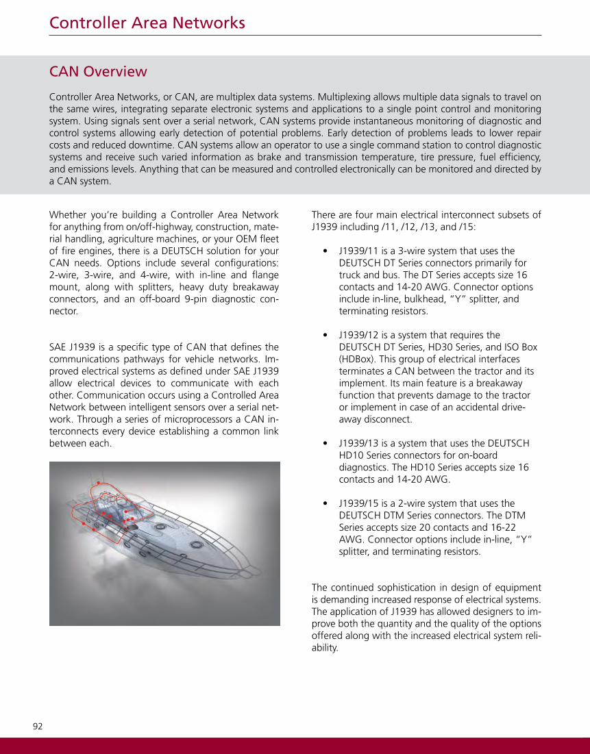
Whether you’re building a Controller Area Network for anything from on/off-highway, construction, mate-rial handling, agriculture machines, or your OEM fleet of fire engines, there is a DEUTSCH solution for your CAN needs. Options include several configurations: 2-wire, 3-wire, and 4-wire, with in-line and flange mount, along with splitters, heavy duty breakaway connectors, and an off-board 9-pin diagnostic con-nector.
SAE J1939 is a specific type of CAN that defines the communications pathways for vehicle networks. Im-proved electrical systems as defined under SAE J1939 allow electrical devices to communicate with each other. Communication occurs using a Controlled Area Network between intelligent sensors over a serial net-work. Through a series of microprocessors a CAN in-terconnects every device establishing a common link between each.
There are four main electrical interconnect subsets of J1939 including /11, /12, /13, and /15:
• J1939/11 is a 3-wire system that uses the DEUTSCH DT Series connectors primarily for truck and bus. The DT Series accepts size 16 contacts and 14-20 AWG. Connector options include in-line, bulkhead, “Y” splitter, and terminating resistors.
• J1939/12 is a system that requires the DEUTSCH DT Series, HD30 Series, and ISO Box (HDBox). This group of electrical interfaces terminates a CAN between the tractor and its implement. Its main feature is a breakaway function that prevents damage to the tractor or implement in case of an accidental drive-away disconnect.
• J1939/13 is a system that uses the DEUTSCH HD10 Series connectors for on-board diagnostics. The HD10 Series accepts size 16 contacts and 14-20 AWG.
• J1939/15 is a 2-wire system that uses the DEUTSCH DTM Series connectors. The DTM Series accepts size 20 contacts and 16-22 AWG. Connector options include in-line, “Y” splitter, and terminating resistors.
The continued sophistication in design of equipment is demanding increased response of electrical systems. The application of J1939 has allowed designers to im-prove both the quantity and the quality of the options offered along with the increased electrical system reli-ability.
CAN Overview
Controller Area Networks, or CAN, are multiplex data systems. Multiplexing allows multiple data signals to travel on the same wires, integrating separate electronic systems and applications to a single point control and monitoring system. Using signals sent over a serial network, CAN systems provide instantaneous monitoring of diagnostic and control systems allowing early detection of potential problems. Early detection of problems leads to lower repair costs and reduced downtime. CAN systems allow an operator to use a single command station to control diagnostic systems and receive such varied information as brake and transmission temperature, tire pressure, fuel efficiency, and emissions levels. Anything that can be measured and controlled electronically can be monitored and directed by a CAN system.
93
Controller Area Networks
J1939/13 Type II Universal 9-pin Diagnostic
DEUTSCH J1939/13, HD10 9 pin connector is a standard diagnostic tool interface for on- and off-highway OEMs. The HD10-9-1939P*-P080 is a data port connector designed to allow an on-board CAN system to mate with a diagnostic computer. The green, Type II connectors, HD10-9-1939P-P080, are for use with the 500 kbps network. The DEUTSCH HD10 J1939/13 connectors offer several mounting options for the receptacle, and a mating plug that is available with or without a coupling ring.
Part Number DescriptionHD10-9-1939P-P080 Receptacle, Flange Mount, Type II
HD10-9-1939PE-P080 Receptacle, Flange Mount, Type II, Reduced Wire Seal
HD10-9-1939P-BP03 Receptacle, Panel Nut Mount, Type II
HD10-9-1939PE-BP03 Receptacle, Panel Nut Mount, Type II, Reduced Wire Seal
HD14-9-1939P-P080 Receptacle, Type II
HD14-9-1939PE-P080 Receptacle, Type II, Reduced Wire Seal
HD16-9-1939S-P080 Plug, Coupling Ring, Type II
HD16-9-1939SE-P080 Plug, Coupling Ring, Type II, Reduced Wire Seal
HD17-9-1939S-P080 Plug, No Coupling Ring (Slip-on), Type II
HD17-9-1939SE-P080 Plug, No Coupling Ring (Slip-on), Type II, Reduced Wire Seal
0460-202-1631 Pin, Solid, Size 16, Gold
0460-247-1631 Pin, Solid, Size 16, Gold, Extended
0462-201-1631 Socket, Solid, Size 16, Gold
0462-221-1631 Socket, Solid, Size 16, Gold,Extended
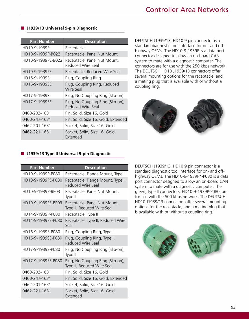
J1939/13 Universal 9-pin Diagnostic
DEUTSCH J1939/13, HD10 9 pin connector is a standard diagnostic tool interface for on- and off-highway OEMs. The HD10-9-1939P is a data port connector designed to allow an on-board CAN system to mate with a diagnostic computer. The connectors are for use with the 250 kbps network. The DEUTSCH HD10 J1939/13 connectors offer several mounting options for the receptacle, and a mating plug that is available with or without a coupling ring.
Part Number DescriptionHD10-9-1939P Receptacle
HD10-9-1939P-B022 Receptacle, Panel Nut Mount
HD10-9-1939PE-B022 Receptacle, Panel Nut Mount, Reduced Wire Seal
HD10-9-1939PE Receptacle, Reduced Wire Seal
HD16-9-1939S Plug, Coupling Ring
HD16-9-1939SE Plug, Coupling Ring, Reduced Wire Seal
HD17-9-1939S Plug, No Coupling Ring (Slip-on)
HD17-9-1939SE Plug, No Coupling Ring (Slip-on), Reduced Wire Seal
0460-202-1631 Pin, Solid, Size 16, Gold
0460-247-1631 Pin, Solid, Size 16, Gold, Extended
0462-201-1631 Socket, Solid, Size 16, Gold
0462-221-1631 Socket, Solid, Size 16, Gold,Extended

94
Controller Area Networks
SAE J1939/11 DEUTSCH Connector Options
DEUTSCH J1939/11 connectors are rugged field proven DT 3 pin connectors designed to meet the SAE requirements for 3-wire CAN applications linking ECUs for serial data communications. The DT 3 way connectors accommodate the CAN_HI, CAN_LO and shield wires with a variety of options including “Y” receptacles, connectors with mounting flanges, keyed wedgelocks to prevent mis-mating, and network terminating connectors with molded-in 120Ω resistors.
Part Number DescriptionDT04-3P-P007 Receptacle, “Y” Connector
DT04-3P-E008 Receptacle, Gray, Shrink Boot Adapter
DT04-3P-P006 Receptacle, Gray, 120 Ohm Resistor
DT04-3P-EE01 Receptacle, Black, Shrink Boot Adapter
DT04-3P-EP10 Receptacle, Black, 120 Ohm Resistor
DT06-3S-E008 Plug, Gray, Shrink Boot Adapter
DT06-3S-P006 Plug, Gray, 120 Ohm Resistor
DT06-3S-EP11 Plug, Black, Shrink Boot Adapter
DT06-3S-PP01 Plug, Black, 120 Ohm Resistor
DT06-3S-PE01 Plug, Black, 120 Ohm Resistor, Latch Guard
DT06-3S-P032 Plug, Black, Single Piece Shrink Boot Adapter
W3P-1939 Wedgelock, Blue
W3S Wedgelock, Orange
W3S-P012 Wedgelock, Green
W3S-1939 Wedgelock, Blue
W3S-1939-P012 Wedgelock, Blue
0460-202-1631 Pin, Solid, Size 16, Gold
1060-16-0144 Pin, Stamped & Formed, Size 16, Gold
0460-247-1631 Pin, Solid, Size 16, Gold, Extended
0462-201-1631 Socket, Solid, Size 16, Gold
1062-16-0144 Socket, Stamped & Formed, Size 16, Gold
0462-221-1631 Socket, Solid, Size 16, Gold, Extended

95
Controller Area Networks
SAE J1939/15 DEUTSCH Connector Options
SAE J1939/15 defines the requirements for reduced physical layer 2-wire CAN systems con-sisting of an unshielded twisted pair of wires. DEUTSCH DTM 2 way connectors are offered in several modifications to meet the requirements of this standard. DTM connectors for serial data communications include “Y” receptacles, connectors with end caps and shrink boot adapters, and receptacles with molded-in 120Ω resistors for network terminations.
Part Number DescriptionDTM04-2P-P007 Receptacle, “Y” ConnectorDTM04-2P-E007 Receptacle, Gray, Shrink Boot AdapterDTM04-2P-P006 Receptacle, Gray, 120 Ohm ResistorDTM04-2P-EE03 Receptacle, Black, Shrink Boot AdapterDTM06-2S-E007 Plug, Gray, Shrink Boot AdapterDTM06-2S-P006 Plug, Gray, 120 Ohm ResistorDTM06-2S-EE03 Plug, Black, Shrink Boot AdapterDTM06-2S-EP10 Plug, Black, 120 Ohm ResistorWM-2P Wedgelock, OrangeWM-2PA Wedgelock, GrayWM-2PB Wedgelock, BlackWM-2S Wedgelock, OrangeWM-2SA Wedgelock, GrayWM-2SB Wedgelock, Black0460-202-2031 Pin, Solid, Size 20, Gold1060-20-0144 Pin, Stamped & Formed, Size 20, Gold0462-201-2031 Socket, Solid, Size 20, Gold1062-20-0144 Socket, Stamped & Formed, Size 20,
Gold
ISO/CD 11783-2 & J1939/12 ISO Box andAssociated Connectors
Originally designed for agricultural applica-tions, the DEUTSCH J1939/12 ISO Box creates a communication pathway between an on-board CAN system and the electronic components on an attached implement. The HDBox, which holds two DT13 connectors and an HD30 Series receptacle, mounts on the vehicle and mates with an HD30 plug connector that features a breakaway coupling ring. DEUTSCH breakaway couplings are designed to help prevent damage to the vehicle or the attached implement by fragmenting and separating from the vehicle in the event of a drive-away disconnect.
Part Number DescriptionHDBOX-24-91PN ISO Box AssemblyHDBOX-24-91PE ISO Box Assembly, Reduced Wire SealHD36-24-91SN-059 Plug, Cable Clamp AssemblyHD36-24-91SE-059 Plug, Cable Clamp Assembly,
Reduced Wire SealHDB36-24-91SN-059 Plug, Breakaway Coupling, Cable
Clamp AssemblyHDB36-24-91SE-059 Plug, Breakaway Coupling, Cable
Clamp Assembly, Reduced Wire SealDT06-4S-EP06* Plug, Black, End CapDT06-2S-EP06* Plug, Black, End CapW4S-P012 Wedgelock, GreenW2S-P012 Wedgelock, Green0460-204-08141 Pin, Solid, Size 80460-204-12141 Pin, Solid, Size 120460-202-1631 Pin, Solid, Size 16, Gold0462-203-08141 Socket, Solid, Size 80462-203-12141 Socket, Solid, Size 120462-201-1631 Socket, Solid, Size 16, Gold
*DT Series receptacles are molded in the HDBox
![DCU 305 R3 CAN / J1939 Manual - Auto-Maskin§ [a] SAE, J1939-71 § [b] SAE, J1939-73 § [c] Conrad Etschberger, “Controller Area Network” ... CAN / J1939 Manual CAN / J1939 –](https://img.pdfslide.us/doc/110x75/5ae535d97f8b9a7b218f6863/dcu-305-r3-can-j1939-manual-auto-maskin-a-sae-j1939-71-b-sae-j1939-73.jpg)