Embed Size (px)
Citation preview
ComponentsPower Supplies and Converters
Generic Product Catalog

Power Supplies and Converters
Table of Contents
SIAP
SIAP (Integrated Power Supply and Protection System).......................................................................................................................... 1SIAP - Generating set [1]....................................................................................................................................................................................... 5SIAP - Mains/GS switchboard [2]....................................................................................................................................................................... 7SIAP - Drive and control panel [3]..................................................................................................................................................................... 9SIAP - PFC switchboard [4]................................................................................................................................................................................ 11SIAP - UPS Subsystem......................................................................................................................................................................................... 13SIAP - Battery cabinets [11]............................................................................................................................................................................... 17SIAP - Emergency network [9].......................................................................................................................................................................... 19SIAP - Direct current branch [10]..................................................................................................................................................................... 21
TALIS48 AC/DC Converter
TALIS power supply module............................................................................................................................................................................. 23TALIS48 Cabinet - 138A.0100001.................................................................................................................................................................... 25TALIS48 Power Supply Module - 138B.0100001........................................................................................................................................ 29
1000Vac Distribution System
1000 Vac distribution - Introduction.............................................................................................................................................................. 331000 Vac - 400/1000 step-up transformer................................................................................................................................................... 371000 Vac - 1000/400 step-down transformer............................................................................................................................................. 39
DC/AC Converter
DC/AC Converter................................................................................................................................................................................................... 415 kVA DC/AC Converter...................................................................................................................................................................................... 4340 kVA DC/AC Converter.................................................................................................................................................................................... 47
Spark gap surge arrester
Spark gap arrester - 100A.0100118................................................................................................................................................................ 51
Appendix
Notes......................................................................................................................................................................................................................... 55
Traceability of Reviews
Table of Reviews.................................................................................................................................................................................................... 57
This publication is AECMA S1000D compliant. I

Generic Product Catalog
II All Rights Reserved. Passing and copying of this document or part of it, use and communication of its contents is not permitted without authorization. © Ansaldo STS.

Power Supplies and Converters
SIA
P
SIAP (Integrated Power Supply and Protection System)SIAP is a power supply and protection system,which fulfils Specification IS732D, charged withsupplying the following equipment andsystems:• interlocking systems• vital (safety-related) equipment• equipment not provided with inherent fail-
safety, the failure of which may howeverimpair service continuity and train missions.
SIAP has been designed, as concerns both architecture andoperation, with the purpose of maximising availability andservice continuity.
SIAP features excellent flexibility and modularity: differentpower sizes (10kVA to 360kVA) have been provided in orderto install top-efficiency configuration according to theparticular energy requirements of the Customer.
SIAP consists of a set of subsystems (housed in cabinetswhich can be set side by side and easy accessible formaintenance operations), with modules installed on slidingpanels which ensure an excellent MTTR rating.
SIAP has been designed and implemented in compliancewith the following Standards: EN61439-1 and EN61439-2,EN60950, EN61000-4-5, IS402, IS732D, EN50121-4,EN50124-1, CEI 64-8.
20kVA 30kVA 40kVA 50kVA 60kVA 75kVA 100kVA
RectifierVin [V] 400 ± 10%Vidcout [V] 264 - 282Imax [A] 110 160 215 270 320 400 540Ibatt max [A] 15 22,5 30 37,5 45 60 7550% load efficiency >90%Nominal PF 0,8
InverterVac out [V] 400 ± 1%Iout nom [A] 28,9 43,4 57,8 72,3 86,7 108,4 144,5Iout cc [A] 66,5 99,7 132,9 166,2 199,4 249,3 332,450% load efficiency >92%Overload 125% / 150% / 200% 10'/1'/1''
BatteriesNo. of celles 120Capacity [Ah] 100 150 200 250 300 400 500idc [A] 114 171 228 304 342 426 570100% load runtime 30'50% load runtime 1h 10'
Table summarizing the main features of the mostcommonly used SIAP systems
This publication is AECMA S1000D compliant. 1
Generic Product Catalog
SIA
P
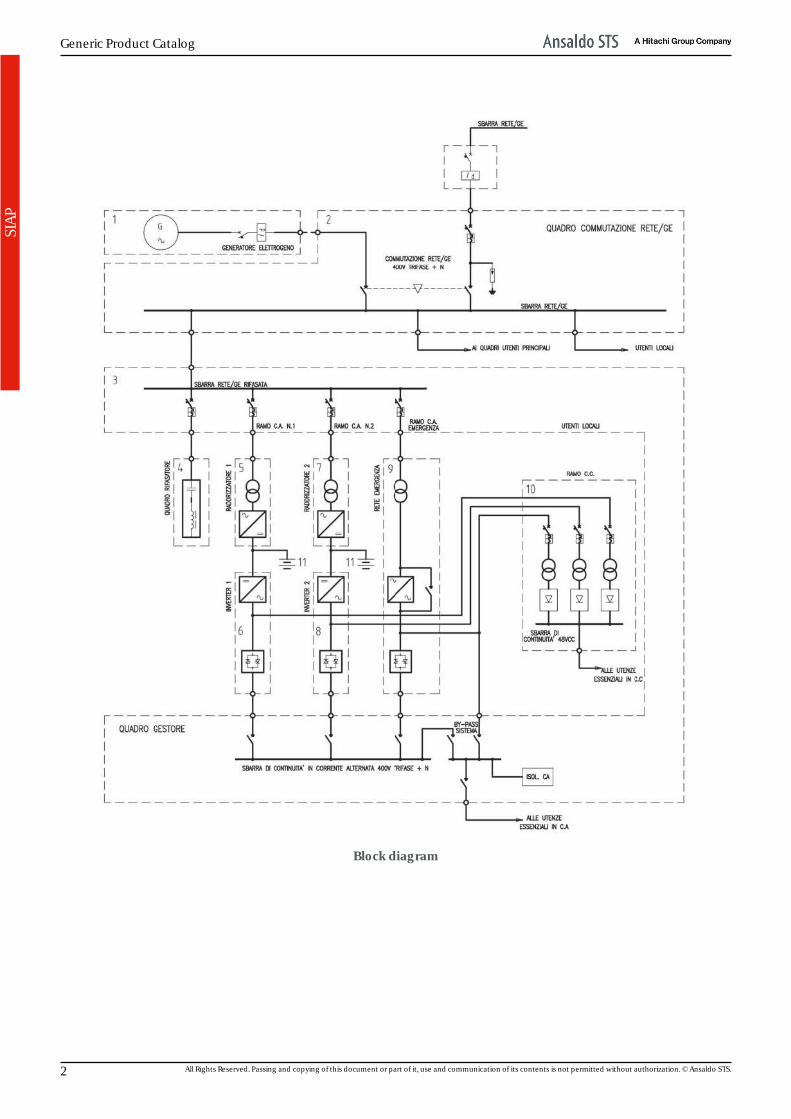
Block diagram
2 All Rights Reserved. Passing and copying of this document or part of it, use and communication of its contents is not permitted without authorization. © Ansaldo STS.
Power Supplies and Converters
SIA
P
This publication is AECMA S1000D compliant. 3

Generic Product Catalog
4 All Rights Reserved. Passing and copying of this document or part of it, use and communication of its contents is not permitted without authorization. © Ansaldo STS.
Power Supplies and Converters
SIA
P
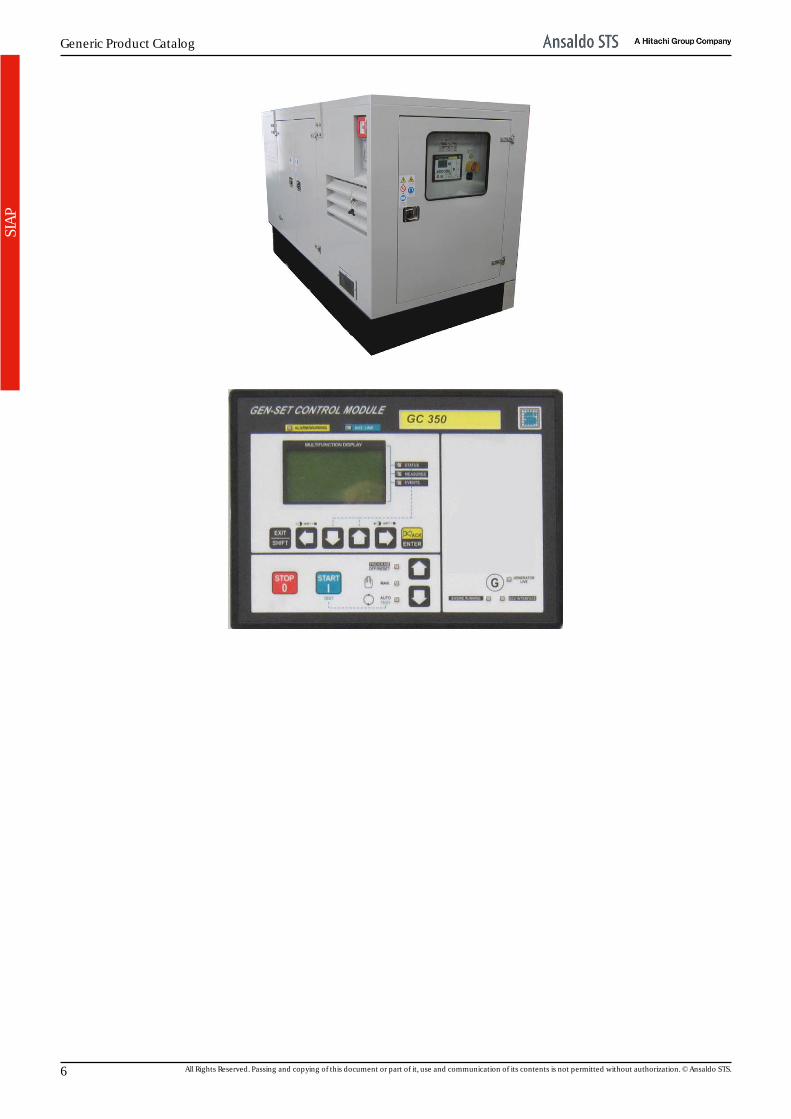
SIAP - Generating set [1]The gen-set is the subsystem charged withstepping in when mains power supply is failing/unavailable. In the event of service mainsvoltage dip, failure or unsuitability, the gen-setshall come into action fully automatically andoperating in the involved area, to providesupply voltage to the system.
Under normal operating conditions, the system is poweredby service mains (typically 400V three-phase). Underemergency conditions, in the event of a voltage dip, avoltage phase failure or also in the event the network voltageexceeds the rated value of a certain threshold (typically ±10%), then the gen-set shall start automatically, shall beoperating in a few seconds and (via remote control switch)shall supply loads on mains/ GS bus bar until service mainsregular conditions are restored. At that point, switch-over tomains takes place automatically after a preset time (typicallyadjustable between 1,5” and 10’) and the automatism forfurther emergency cycles will be reset. After switching tomains, gen-set will stop after a preset time (adjustablebetween 1,5” and 10’) to allow self-cooling.
The generating set consists of the following components:• diesel engine (diesel, four-stroke, water-cooled,
multicylinder, in-line or V-type engine, characterized by acyclic failure rate ≤ 1/75). Rated output defined byStandard ISO 8528-1, 1500 rpm, continuous duty, toobviate prolonged network failures, 10% overload of ratedoutput is admitted for 1 hour duration every 12 hours ofoperation under rated load
• service tank (manufactured, installed and equipped withsafety devices); also preset for connection to a storagetank, if any. It can be equipped with electric and handpump for filling from stock tanks. Service tank is suppliedby forced-circulation only. Fuel piping is provided with arapid closing on-off valve that can be remote controlledfrom the outside of the gen-set premises
• silencer (> = 30 dB/A exhaust noise reduction) completewith piping and fittings
• radiator (dimensioned to operate with exchange air atinlet with temperature not lower than 50 °C, it guaranteeslow acoustic impact in compliance with Standard UNI EN12601 and current regulations in force)
• storage battery (24V, proper capacity, rechargeable bybattery charger powered by mains - when present - andby the set during its operation. Backup and constantcurrent charge is provided with automatic operationtransition)
• alternator with X’’<3% subtransient reactance formachines up to 100kVA and <4% for machines up to300kVA and <6% for higher sizes (electric generator,coupled coaxially to the diesel engine and thereforeoperating at 1500 rpm, synchronous, brushless andwithout slip rings, self-excited, compensated and self-regulating, damping cage, mechanical protection ratingnot lower than IP44)
• power circuit (IP20 protection rating)• auxiliary services (electronic automatic battery charger
fed by load line, single-phase voltage supply for enginepre-heating, acoustic alarm, programmable automatictest, event log and digital clock built into the GC350 board)
• controls (AUTO/MAN/TEST operation)• digital gauges and instruments (low oil pressure, high
water temperature, over speed, low fuel level, repeatedstarting attempts, etc.)
• protections (a backlit LCD display is provided for checkingthe gen-set operating condition and for displayingprotection triggering).
This publication is AECMA S1000D compliant. 5
Generic Product Catalog
SIA
P
6 All Rights Reserved. Passing and copying of this document or part of it, use and communication of its contents is not permitted without authorization. © Ansaldo STS.
Power Supplies and Converters
SIA
P
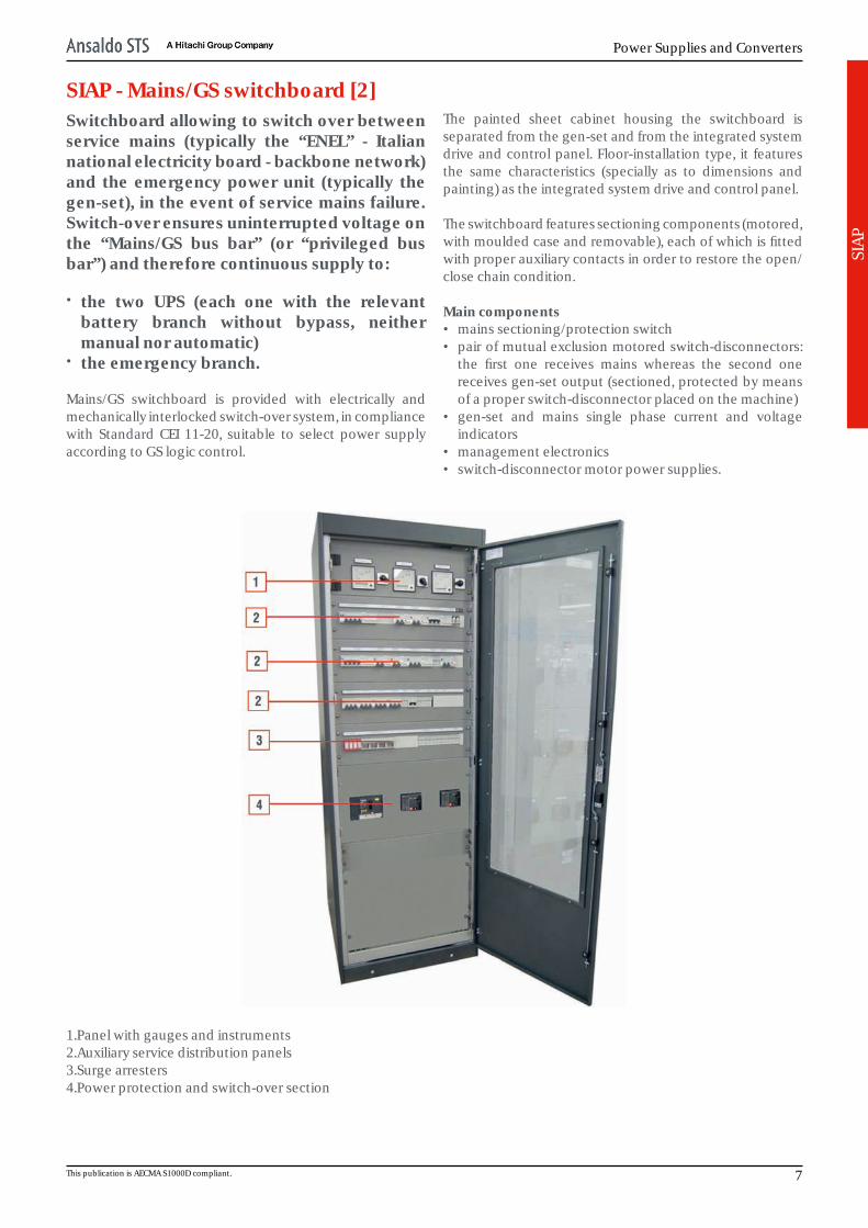
SIAP - Mains/GS switchboard [2]Switchboard allowing to switch over betweenservice mains (typically the “ENEL” - Italiannational electricity board - backbone network)and the emergency power unit (typically thegen-set), in the event of service mains failure.Switch-over ensures uninterrupted voltage onthe “Mains/GS bus bar” (or “privileged busbar”) and therefore continuous supply to:
• the two UPS (each one with the relevantbattery branch without bypass, neithermanual nor automatic)
• the emergency branch.
Mains/GS switchboard is provided with electrically andmechanically interlocked switch-over system, in compliancewith Standard CEI 11-20, suitable to select power supplyaccording to GS logic control.
The painted sheet cabinet housing the switchboard isseparated from the gen-set and from the integrated systemdrive and control panel. Floor-installation type, it featuresthe same characteristics (specially as to dimensions andpainting) as the integrated system drive and control panel.
The switchboard features sectioning components (motored,with moulded case and removable), each of which is fittedwith proper auxiliary contacts in order to restore the open/close chain condition.
Main components• mains sectioning/protection switch• pair of mutual exclusion motored switch-disconnectors:
the first one receives mains whereas the second onereceives gen-set output (sectioned, protected by meansof a proper switch-disconnector placed on the machine)
• gen-set and mains single phase current and voltageindicators
• management electronics• switch-disconnector motor power supplies.
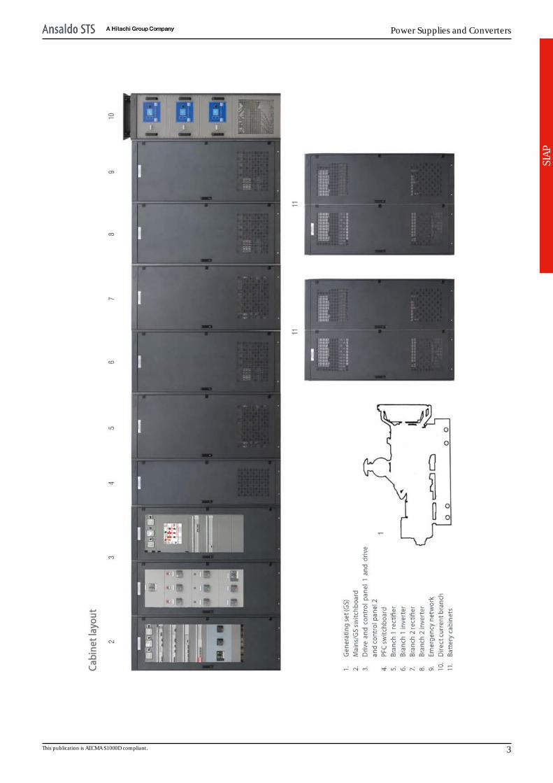
1.Panel with gauges and instruments2.Auxiliary service distribution panels3.Surge arresters4.Power protection and switch-over section
This publication is AECMA S1000D compliant. 7

Generic Product Catalog
8 All Rights Reserved. Passing and copying of this document or part of it, use and communication of its contents is not permitted without authorization. © Ansaldo STS.
Power Supplies and Converters
SIA
P
SIAP - Drive and control panel [3]It allows electric sectioning and removal ofeach branch or functional subassembly,individually, without generating malfunctionsof any type to the whole system and undersafety conditions. In particular, it keepsunaltered the distribution system during thedfferent sectioning or by-pass operations.
All protection and sectioning devices specified in CEIStandards for each subassembly are provided andcoordinated with each other. Each sectioning component isfitted with proper auxiliary contacts in order to implementrelevant diagnostic.
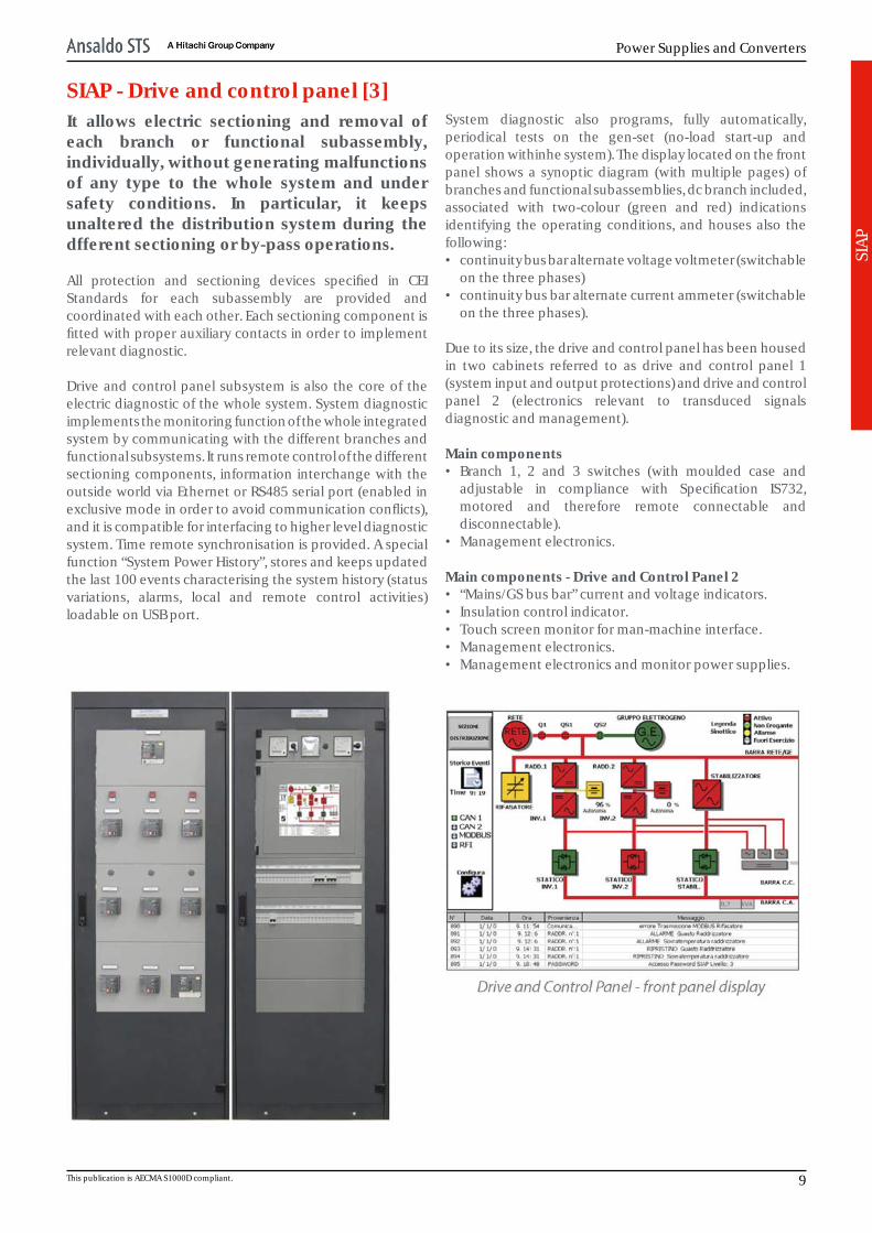
Drive and control panel subsystem is also the core of theelectric diagnostic of the whole system. System diagnosticimplements the monitoring function of the whole integratedsystem by communicating with the different branches andfunctional subsystems. It runs remote control of the differentsectioning components, information interchange with theoutside world via Ethernet or RS485 serial port (enabled inexclusive mode in order to avoid communication conflicts),and it is compatible for interfacing to higher level diagnosticsystem. Time remote synchronisation is provided. A specialfunction “System Power History”, stores and keeps updatedthe last 100 events characterising the system history (statusvariations, alarms, local and remote control activities)loadable on USB port.
System diagnostic also programs, fully automatically,periodical tests on the gen-set (no-load start-up andoperation withinhe system). The display located on the frontpanel shows a synoptic diagram (with multiple pages) ofbranches and functional subassemblies, dc branch included,associated with two-colour (green and red) indicationsidentifying the operating conditions, and houses also thefollowing:• continuity bus bar alternate voltage voltmeter (switchable
on the three phases)• continuity bus bar alternate current ammeter (switchable
on the three phases).
Due to its size, the drive and control panel has been housedin two cabinets referred to as drive and control panel 1(system input and output protections) and drive and controlpanel 2 (electronics relevant to transduced signalsdiagnostic and management).
Main components• Branch 1, 2 and 3 switches (with moulded case and
adjustable in compliance with Specification IS732,motored and therefore remote connectable anddisconnectable).
• Management electronics.
Main components - Drive and Control Panel 2• “Mains/GS bus bar” current and voltage indicators.• Insulation control indicator.• Touch screen monitor for man-machine interface.• Management electronics.• Management electronics and monitor power supplies.
This publication is AECMA S1000D compliant. 9
Generic Product Catalog
SIA
P
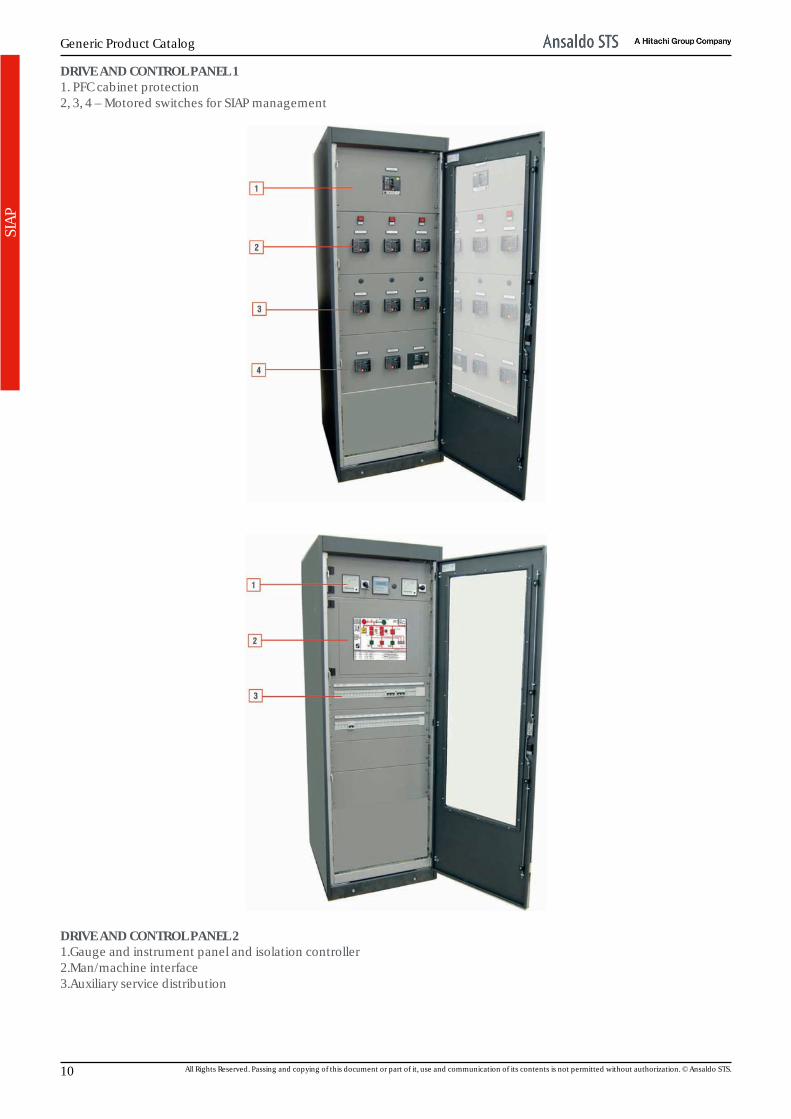
DRIVE AND CONTROL PANEL 11. PFC cabinet protection2, 3, 4 – Motored switches for SIAP management
DRIVE AND CONTROL PANEL 21.Gauge and instrument panel and isolation controller2.Man/machine interface3.Auxiliary service distribution
10 All Rights Reserved. Passing and copying of this document or part of it, use and communication of its contents is not permitted without authorization. © Ansaldo STS.

Power Supplies and Converters
SIA
P
SIAP - PFC switchboard [4]Regulator including power factor correctionand harmonic filters for bringing SIAP toexcellent electric efficiency level. The core ofthe controller is a DSP processor allowing fastand efficient implementation of correctionalgorithms.
Main components• two 19” rack modules containing power components
divided into five separate areas• capacitor protection inductance which prevents resonant
phenomena and therefore overcurrents• static switches for the connection of the most suitable
specific capacity with the maximum reliability.
1.Management logic control panel2.Removable module with three PFC capacitors3.Removable module with two PFC capacitors4.Removable panel for accessing five static switches5.Removable panel for accessing terminal blocks
This publication is AECMA S1000D compliant. 11

Generic Product Catalog
12 All Rights Reserved. Passing and copying of this document or part of it, use and communication of its contents is not permitted without authorization. © Ansaldo STS.
Power Supplies and Converters
SIA
P
SIAP - UPS SubsystemThis unit allows the system to provideuninterrupted power supply to the essentialbus bar loads, regardless of service mains (AC)condition.
UPS guarantees reliable voltage and frequency stabilizedsupply voltage, free from network noise, within tolerancevalues compatible with the requirements of the electronicequipment placed after it, using in the event of mains failure,a stationary power supply (battery) sufficient to ensureproper load supply runtime. UPS architecture is of the doubleconversion type, since two voltage conversions areimplemented at system input and output.
First conversion: AC/DC, is implemented by a rectifier,second conversion: DC/AC, is implemented by an inverter.
BRANCH 1 [5] and 2 [7] RECTIFIERSRectifiers are AC/DC converters charged with the following:• supply the relevant inverters placed downstream• keep charged the relevant backup batteries which cut-in
when “Mains/GS bus bar” is powered off.
Rectifier/battery charger is of the three-phase, 12-pulse, SCRtype and is charged with converting alternate current todirect current. At input, a voltage regulation/isolationtransformer is used which together with inductors placed atconversion bridge output (DC side), shall reduce networkdistortion produced by rectifier and ripple to battery,thereby ensuring battery max. life-cycle. Rectifier DC outputis charged with supplying both the inverter and the battery.
Rectifier has been designed for supplying at the same timeboth the inverter (under max load conditions) and thebattery (with max recharge current).
Rectifier main components• Isolation transformer specific for 12-pulse rectifier.• Double three-phase bridge, forced air-cooled (up to
20kVA).• Polyester film capacitors, with MTBF = 100.000h@ 85°C.• Control electronics housed on extractable module, led
diagnostic and microprocessor control.• Components mounted on sliding plates to enhance
accessibility and maintenance, and to minimise the MTTR.
This publication is AECMA S1000D compliant. 13

Generic Product Catalog
SIA
P
RECTIFIER CABINET1.Twelve-phase rectifier, SCR type2.Blocking diodes3.Management electronics4.Condenser bank5.Coupling inductances6.Battery switch7.Cable inlet terminal block panel8.Double secondary insulation transformer
14 All Rights Reserved. Passing and copying of this document or part of it, use and communication of its contents is not permitted without authorization. © Ansaldo STS.

Power Supplies and Converters
SIA
P
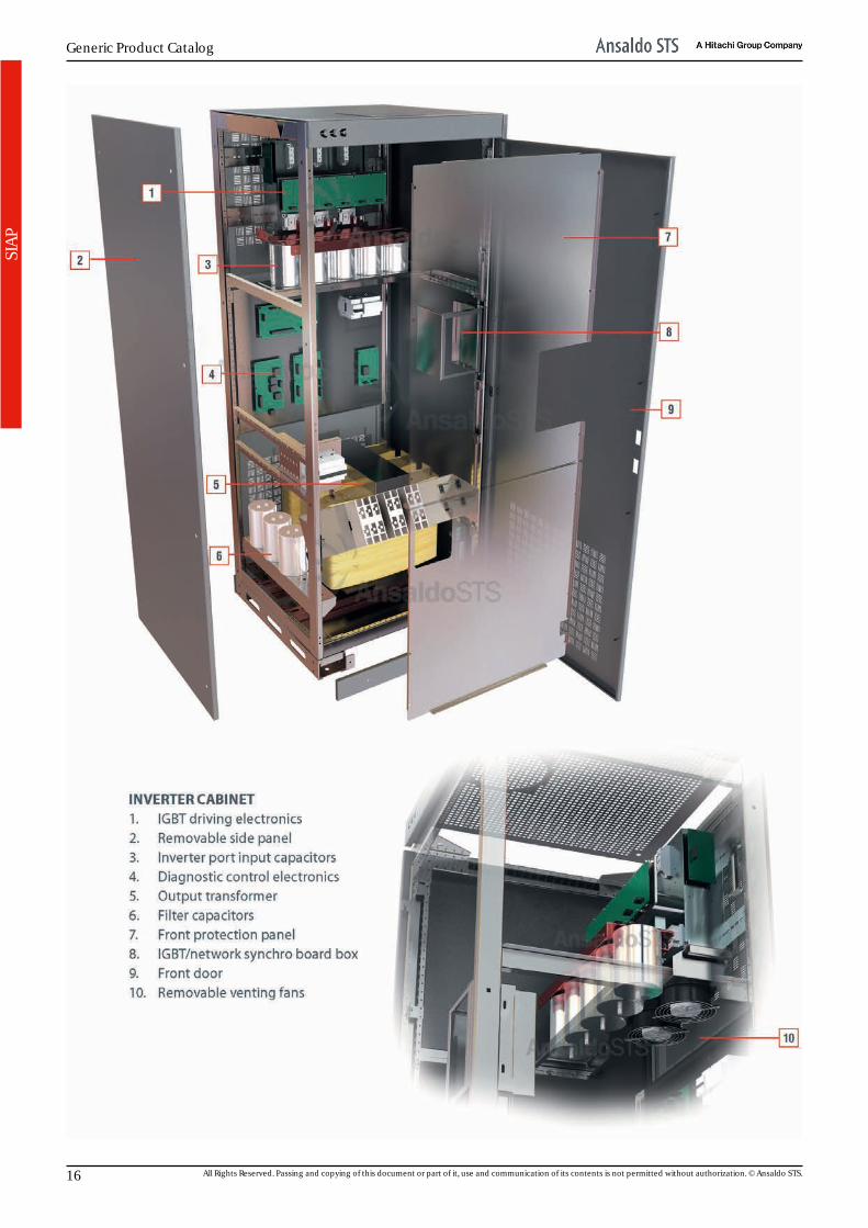
BRANCH 1 [6] and 2 [8] INVERTERS
Inverter transforms Vdc direct voltage supplied by rectifieror battery to Vac alternate voltage, perfectly stabilised infrequency and amplitude. Inverter output voltage isgenerated with IGBT-driving pulse width modulation (PWM).Using high carrier frequency for PWM and proper AC filteringcircuit (consisting of transformer and capacitors), ensuresmin output voltage distortion (THD <2% on linear loads).
Inverter output logic is controlled by the control logic, thusensuring constant and equal voltages at UPS output, alsowith unbalanced loads. Harmonic distortion at output is keptat low levels thanks to a unique adaptation correctiontechnique, also with the application of high distorted loads.Inverter control logic reduces the max output current to200% of rated current in the event of a short circuit.
In the event of overlaod (up to 200% of rated current), outputvoltage is kept constant. For higher currents the outputvoltage is reduced; this however will only take place if bypasspower supply is not available. Inverter IGBT transistors arefully protected against serious short circuits thanks to a de-saturation control or “electronic fuse”.
Each inverter is fitted with two output sockets:• one before the static switch, destined to power the DC
network• one after the static switch for powering the “continuity bus
bar”.
Inverter main components• IGBT bridges for phase generation.• LC type filter on AC side.• Output transformer, complying with Specification IS732D,
delta winding at input and star winding at output.• Drive electronics on extractable module.• Control electronics.• Polyester film capacitors with MTBF 100.000h@85°C.• Components mounted on sliding plates to enhance
accessibility and maintenance, and to minimise the MTTR.
This publication is AECMA S1000D compliant. 15
Generic Product Catalog
SIA
P
16 All Rights Reserved. Passing and copying of this document or part of it, use and communication of its contents is not permitted without authorization. © Ansaldo STS.
Power Supplies and Converters
SIA
P
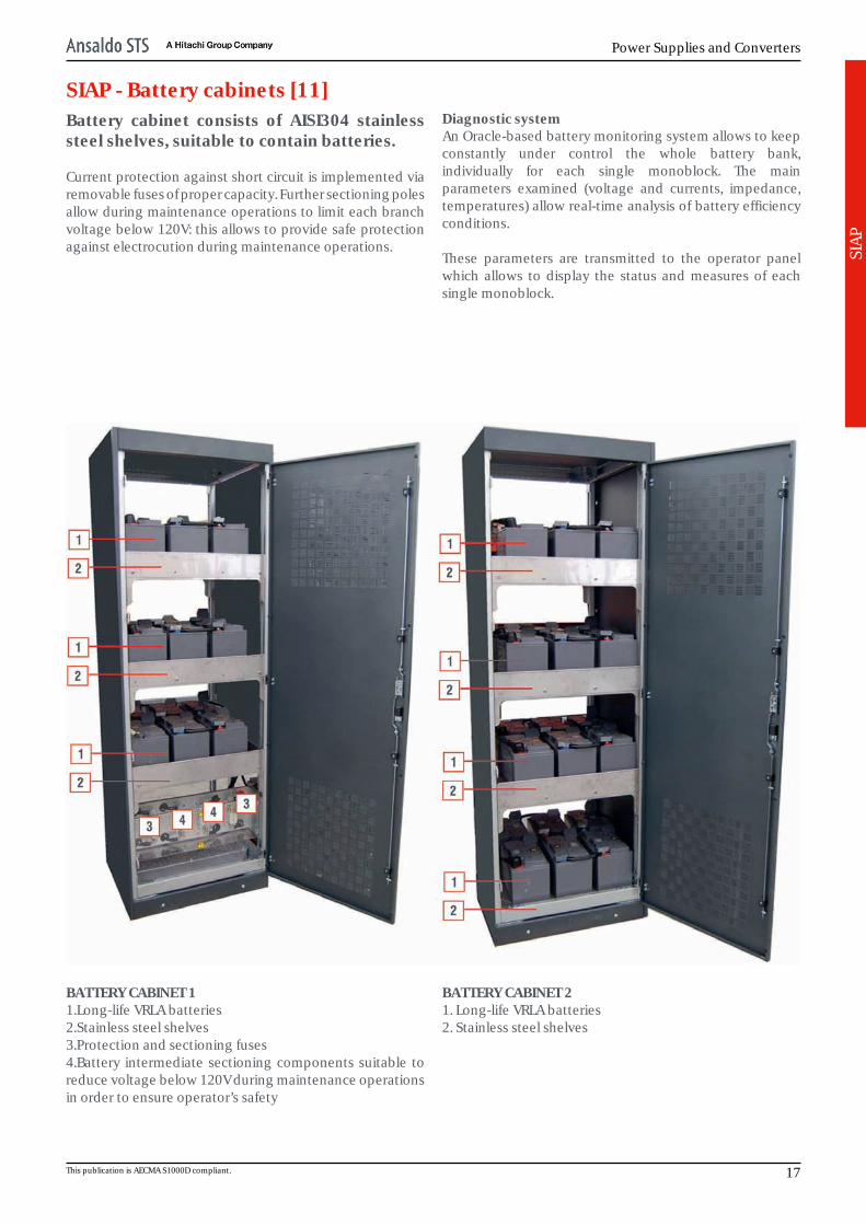
SIAP - Battery cabinets [11]Battery cabinet consists of AISI304 stainlesssteel shelves, suitable to contain batteries.
Current protection against short circuit is implemented viaremovable fuses of proper capacity. Further sectioning polesallow during maintenance operations to limit each branchvoltage below 120V: this allows to provide safe protectionagainst electrocution during maintenance operations.
Diagnostic systemAn Oracle-based battery monitoring system allows to keepconstantly under control the whole battery bank,individually for each single monoblock. The mainparameters examined (voltage and currents, impedance,temperatures) allow real-time analysis of battery efficiencyconditions.
These parameters are transmitted to the operator panelwhich allows to display the status and measures of eachsingle monoblock.
BATTERY CABINET 11.Long-life VRLA batteries2.Stainless steel shelves3.Protection and sectioning fuses4.Battery intermediate sectioning components suitable toreduce voltage below 120V during maintenance operationsin order to ensure operator’s safety
BATTERY CABINET 21. Long-life VRLA batteries2. Stainless steel shelves
This publication is AECMA S1000D compliant. 17

Generic Product Catalog
18 All Rights Reserved. Passing and copying of this document or part of it, use and communication of its contents is not permitted without authorization. © Ansaldo STS.
Power Supplies and Converters
SIA
P
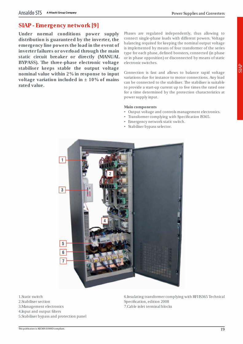
SIAP - Emergency network [9]Under normal conditions power supplydistribution is guaranteed by the inverter, theemergency line powers the load in the event ofinverter failures or overload through the mainstatic circuit breaker or directly (MANUALBYPASS). The three-phase electronic voltagestabiliser keeps stable the output voltagenominal value within 2% in response to inputvoltage variation included in ± 10% of mainsrated value.
Phases are regulated independently, thus allowing toconnect single-phase loads with different powers. Voltagebalancing required for keeping the nominal output voltageis implemented by means of four transformer of the seriestype for each phase, defined boosters, connected (in phaseor in phase opposition) or disconnected by means of staticelectronic switches.
Connection is fast and allows to balance rapid voltagevariations due for instance to motor connections. Any loadcan be connected to the stabiliser. The stabiliser is suitableto provide a start-up current up to five times the rated onefor a time determined by the protection characteristics atpower supply input.
Main components• Output voltage and controls management electronics.• Transformer complying with Specification IS365.• Emergency network static switch.• Stabiliser bypass selector.
1.Static switch2.Stabiliser section3.Management electronics4.Input and output filters5.Stabiliser bypass and protection panel
6.Insulating transformer complying with RFI IS365 TechnicalSpecification, edition 20087.Cable inlet terminal blocks
This publication is AECMA S1000D compliant. 19

Generic Product Catalog
20 All Rights Reserved. Passing and copying of this document or part of it, use and communication of its contents is not permitted without authorization. © Ansaldo STS.
Power Supplies and Converters
SIA
P
SIAP - Direct current branch [10]The Direct Current branch basically consists oflinear (non switching) power supply modules(typically “TALIS48”), with parallelable output,suitable to generate - starting from 400 Vacthree-phase voltage without neutral - 48 Vdcrated output unregulated direct voltage.Power supply modules are typically installed ina proper pre-wired rack, thus making itpossible to obtain a redundant power supplysystem.
TALIS48 power supply module (400 Vac/48 Vdc) has beenmanufactured according to Safety Extra-Low Voltage (SELV)requirements in compliance with RFI Specifications.
Main componentsThe DC branch typically houses the following:• a three-pole switch disconnector (acting as machine
switch)• a power supply input EMI filter (differential mode only)• an insulating transformer with further uprating of
insulation voltage at 8 kV between primary and secondarywinding
• a twelve-phase rectifier (for dual three-phase line) housedonto a vertical heat sink made of extruded aluminium
• an interphase coil used to adapt, on the direct current side,the voltage obtained from both three-phase rectifiers
• a pair of diodes placed after the interphase coil with thefunction of further reducing the THD
• diagnostic subsystem based on microprocessor boardcharged with acquiring states and measures, localprocessing for diagnostic purposes, controlling local tripunits following the occurrence of a fault, communicatingdiagnostic data and measures
• LED synoptic display showing the operating state of themain components, represented by means of a screen-printed block diagram
• diagnostic display for displaying the operating conditionand the electrical measures
• a port used for data exchange with the machine on-boardmicroprocessor, for firmware updating and/or log datadownloading.
This publication is AECMA S1000D compliant. 21
Generic Product Catalog
SIA
P
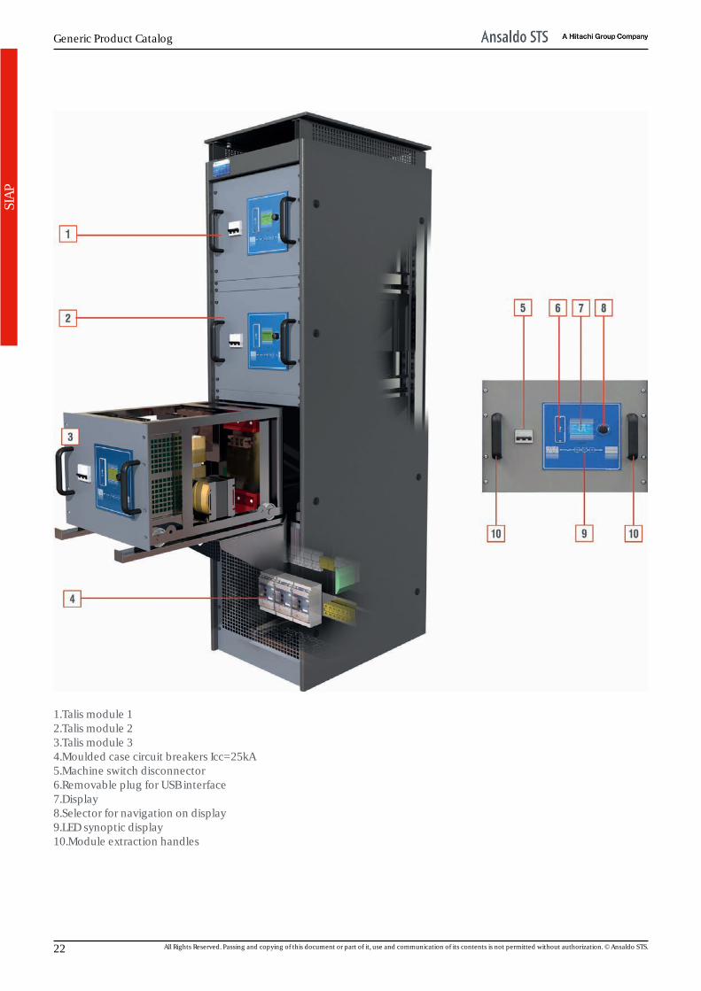
1.Talis module 12.Talis module 23.Talis module 34.Moulded case circuit breakers Icc=25kA5.Machine switch disconnector6.Removable plug for USB interface7.Display8.Selector for navigation on display9.LED synoptic display10.Module extraction handles
22 All Rights Reserved. Passing and copying of this document or part of it, use and communication of its contents is not permitted without authorization. © Ansaldo STS.

Power Supplies and Converters
TALI
S48
AC/
DC
Conv
erte
r
TALIS power supply moduleThe product being dealt with is a component of the signalling equipment power supply system.It consists of power supply modules with 400 Vac three-phase input voltage and 24 Vdc, 48 Vdcand/or 144 Vdc outputs. In particular the TALIS48 version has been designed expressly forpowering the 48 Vdc signalling electronic equipment.
This publication is AECMA S1000D compliant. 23
Generic Product Catalog
TALI
S48
AC/
DC
Conv
erte
r
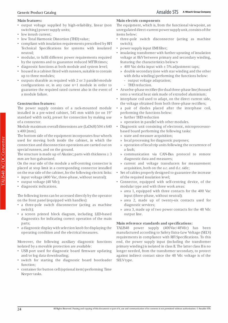
Main features:• output voltage supplied by high-reliability, linear (non
switching) power supply units;• low inrush current;• low Total Harmonic Distortion (THD) value;• compliant with insulation requirements prescribed by RFI
Technical Specifications for systems with insulatedneutral;
• modular, to fulfil different power requirements requiredby the systems and to guarantee reduced MTTR times;
• diagnostic functions at both module and system level;• housed in a cabinet fitted with runners, suitable to contain
up to three modules;• outputs sharable as required with 2 or 3 parallel-module
configurations or, in any case n+1 module in order toguarantee the required rated current also in the event ofa module failure.
Construction features:The power supply consists of a rack-mounted moduleinstalled in a pre-wired cabinet, 545 mm width (or on 19"standard width rack), preset for connection by making useof a connector.Module maximum overall dimensions are (LxDxH) 504 x 640x 400 [mm].The bottom side of the equipment incorporates four wheelsused for moving both inside the cabinet, in which theconnection and disconnection operations are carried out onspecial runners, and on the ground.The structure is made up of Aluzinc; parts with thickness ≥ 3mm are hot-galvanized.On the rear side of the module a self-centring connector isplaced at stop limit in a corresponding connector installedon the rear side of the cabinet, for the following electric links:• input voltage (400 Vac, three-phase, without neutral);• output voltage (48 Vdc);• diagnostic indications. The following items can be accessed directly by the operatoron the front panel (equipped with handles):• a three-pole switch disconnector (acting as machine
switch);• a screen printed block diagram, including LED-based
diagnostics for indicating correct operation of the mainparts;
• a diagnostic display with selection knob for displaying theoperating condition and the electrical measures.
Moreover, the following auxiliary diagnostic functionsisolated by a movable protection are available:• USB port used for diagnostic board firmware updating
and/or log data downloading;• switch for starting the diagnostic board bootloader
function;• container for button cell (optional item) performing Time
Keeper tasks.
Main electric componentsThe equipment, which is, from the functional viewpoint, anunregulated direct-current power supply unit, consists of theitems below:• three-pole switch disconnector (acting as machine
switch);• power supply input EMI filter;• insulating transformer with further uprating of insulation
voltage at 8kV between primary and secondary winding,featuring the characteristics below:v» 400 Vac delta input with ± 5% adjustment taps;» double secondary (one with star winding and the other
with delta winding) performing the functions below:- output voltage adaptation;- THD reduction.
• A twelve-phase rectifier (for dual three-phase line) housedonto a vertical heat sink made of extruded aluminium;
• interphase coil used to adapt, on the direct current side,the voltage obtained from both three-phase rectifiers;
• a pair of diodes placed after the interphase coil,performing the functions below:» further THD reduction» operation in parallel with other modules.
• Diagnostic unit consisting of electronic, microprocessor-based board performing the following tasks:» state and measure acquisition;» local processing for diagnostic purposes;» operation of local trip units following the occurrence of
a fault;» communication via CAN-Bus protocol to remote
diagnostic data and measures;» current and voltage transducers for measurement
acquisition, both on the a.c. and d.c. side;• Set of cables properly designed to guarantee the increase
of the required insulation level;• Connector, equipped with self-centring device, of the
modular type and with three work areas:» area 1, equipped with three contacts for the 400 Vac
input (three-phase, without neutral);» area 2, made up of twenty-six contacts used for
diagnostic services;» area 3, made up of two power contacts for the 48 Vdc
output line. Main reference standards and specifications:TALIS48 power supply (400Vac/48Vdc) has beenmanufactured according to Safety Extra-Low Voltage (SELV)requirements in compliance with RFI Specifications. To thisend, the power supply input (including the transformerprimary winding) is isolated in class II. The latter class II is nolonger needed, from the transformer secondary, to protectagainst indirect contact since the 48 Vdc voltage is of theSELV type.
24 All Rights Reserved. Passing and copying of this document or part of it, use and communication of its contents is not permitted without authorization. © Ansaldo STS.
Power Supplies and Converters
TALI
S48
AC/
DC
Conv
erte
r
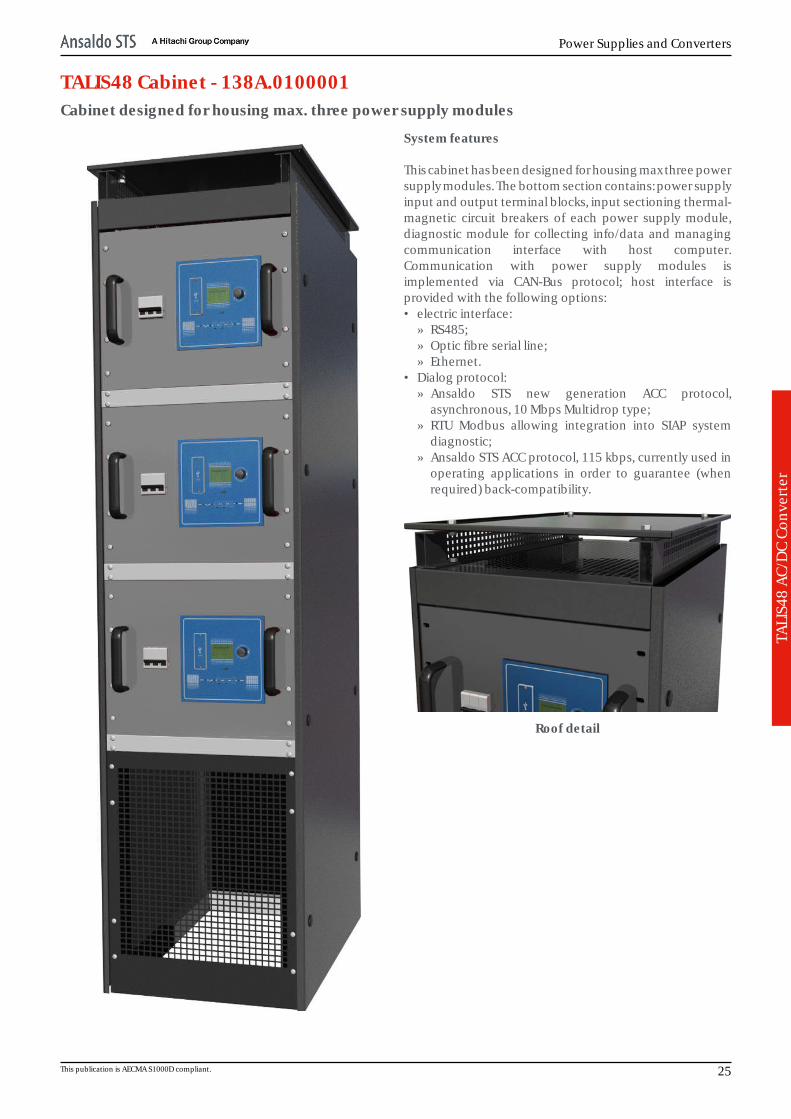
TALIS48 Cabinet - 138A.0100001Cabinet designed for housing max. three power supply modules
System features This cabinet has been designed for housing max three powersupply modules. The bottom section contains: power supplyinput and output terminal blocks, input sectioning thermal-magnetic circuit breakers of each power supply module,diagnostic module for collecting info/data and managingcommunication interface with host computer.Communication with power supply modules isimplemented via CAN-Bus protocol; host interface isprovided with the following options:• electric interface:
» RS485;» Optic fibre serial line;» Ethernet.
• Dialog protocol:» Ansaldo STS new generation ACC protocol,
asynchronous, 10 Mbps Multidrop type;» RTU Modbus allowing integration into SIAP system
diagnostic;» Ansaldo STS ACC protocol, 115 kbps, currently used in
operating applications in order to guarantee (whenrequired) back-compatibility.
Roof detail
This publication is AECMA S1000D compliant. 25

Generic Product Catalog
TALI
S48
AC/
DC
Conv
erte
r
General featuresPart number: 138A.0100001Format:Dimens. [l, h, d] [mm]:Front panel:
545, 2.050, 64044U x 19"
MTBF [h]:Weight [Kg]:Front panel colour:Working temperature [C]:Storage temperature [C]:Vibrations:Altitude [m]:Relative humidity:
- 25 ÷ 70- 25 ÷ 85
compliant with IS 402 group 2V< 1.500
95% without condensate (@ 40 °C)Composition:Obsolescence:HW revision:SW revision:SW file:Naming:
NO
Certifications:
CEI EN50125-2; CEI EN50125-5;CEI EN50125-4-1; CEI EN50124-1/A1/A2;
CEI EN61000-4-1; CEI EN61000-6-2;CEI EN50121-1; CEI 64-8; CEI 64-8 V1;
CEI 64-8 V2; CEI EN60950-1; CEI EN60439-1;CEI 1743; UL94/V1; 98/37/EC directive.
Technical featuresPaint film thicknessMedium [μm]: xxMinimum [μm]: xxStructural steelwork: zinc-coated parts for 3 mm thicknesses, and Aluzincfor the other partsPaint type: polyester powder
Technical features subject to variation without notice.
Cabinet block diagram
26 All Rights Reserved. Passing and copying of this document or part of it, use and communication of its contents is not permitted without authorization. © Ansaldo STS.
Power Supplies and Converters
TALI
S48
AC/
DC
Conv
erte
r
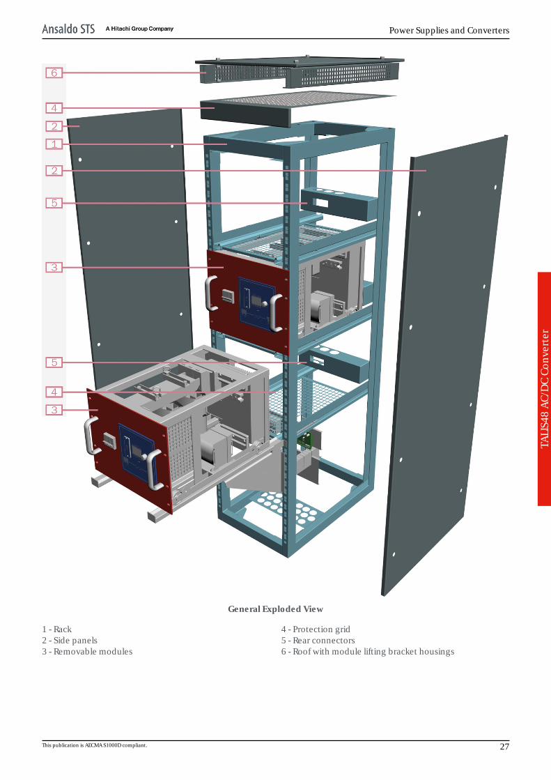
General Exploded View
1 - Rack2 - Side panels3 - Removable modules
4 - Protection grid5 - Rear connectors6 - Roof with module lifting bracket housings
This publication is AECMA S1000D compliant. 27
Generic Product Catalog
TALI
S48
AC/
DC
Conv
erte
r
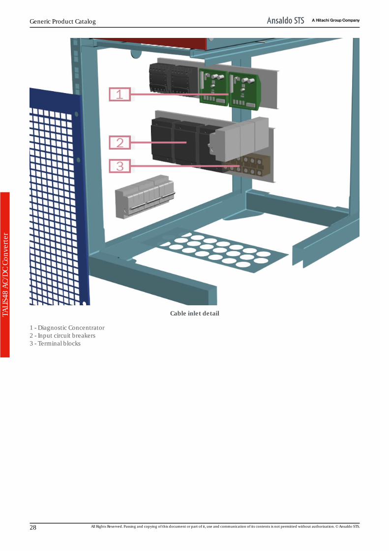
Cable inlet detail
1 - Diagnostic Concentrator2 - Input circuit breakers3 - Terminal blocks
28 All Rights Reserved. Passing and copying of this document or part of it, use and communication of its contents is not permitted without authorization. © Ansaldo STS.

Power Supplies and Converters
TALI
S48
AC/
DC
Conv
erte
r
TALIS48 Power Supply Module - 138B.010000148 Vdc output power supply module
Diagnostic circuit functions The power supply module houses a diagnostic board whichallows to acquire a number of analog and digital signals tobe provided to loads via RS-485 serial line with CAN-Busprotocol.Analog signals (10-bit acquisition and 1% precision)provided are the following:• input voltage;• input current;• output voltage before the insulation diode;• output voltage after the insulation diode;• output current;• internal temperature and heat sink temperatureDigital signals provided are the following:• main circuit breaker state;• insulation transformer temperature rise. Diagnostic display functions The power supply front panel features a diagnostic displayequipped with a selection knob for choosing required infoand data to be displayed.
Diagnostic display and LED-diagram detail
This publication is AECMA S1000D compliant. 29
Generic Product Catalog
TALI
S48
AC/
DC
Conv
erte
r
General featuresPart number: 138B.0100001Format:Dimensions [l, h, d] [mm]:Front panel:
504, 400, 6409U x 19"
MTBF [power supply module] [h]:MTBF [SCD48] [h]:MTBF [SCM48] [h]:
1.000.000 (@ 25° C)250.000 (@ 25° C)250.000 (@ 25° C)
Weight [kg]: ~ 80Front panel colour: RAL3003Working temperature [C]:Storage temperature [C]:Vibrations:Altitude [m]:Relative humidity:
- 25 ÷ 70- 25 ÷ 85
compliant with IS 402 group 2V< 1.500
95% without condensate (@ 40 °C)Composition:Obsolescence:HW revision:SW revision:SW file:Naming:
NO
Certifications:
CEI EN50125-2; CEI EN50125-5;CEI EN50125-4-1; CEI EN50124-1/A1/
A2;CEI EN61000-4-1; CEI EN61000-6-2;
CEI EN50121-1; CEI 64-8; CEI 64-8 V1;CEI 64-8 V2; CEI EN60950-1; CEI
EN60439-1;CEI 1743; UL94/V1; 98/37/EC directive
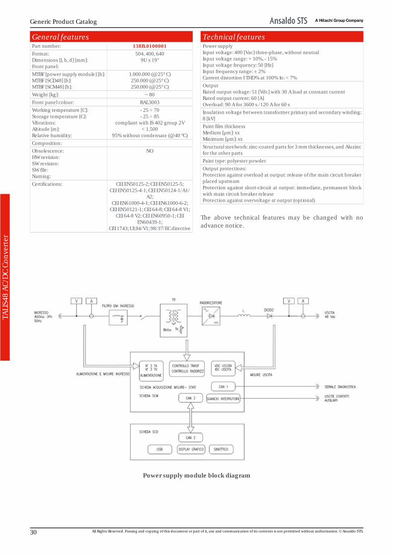
Technical featuresPower supplyInput voltage: 400 [Vac] three-phase, without neutralInput voltage range: + 10%, - 15%Input voltage frequency: 50 [Hz]Input frequency range: ± 2%Current distortion I THD% at 100% Io: < 7%OutputRated output voltage: 51 [Vdc] with 30 A load at constant currentRated output current: 60 [A]Overload: 90 A for 3600 s /120 A for 60 sInsulation voltage between transformer primary and secondary winding:8 [kV]Paint film thicknessMedium [μm]: xxMinimum [μm]: xxStructural steelwork: zinc-coated parts for 3 mm thicknesses, and Aluzincfor the other partsPaint type: polyester powderOutput protections:Protection against overload at output: release of the main circuit breakerplaced upstreamProtection against short-circuit at output: immediate, permanent blockwith main circuit breaker releaseProtection against overvoltage at output (optional)
The above technical features may be changed with noadvance notice.
Power supply module block diagram
30 All Rights Reserved. Passing and copying of this document or part of it, use and communication of its contents is not permitted without authorization. © Ansaldo STS.

Power Supplies and Converters
TALI
S48
AC/
DC
Conv
erte
rRack - Front view
1 - Front panel2 - Three-pole switch connector3 - Removable panel for accessing the auxiliary diagnosticfunctions4 - Diagnostic and control display panel
5 - Extraction handles6 - Interphase coil7- Main transformer8 - Wheels for moving the rack along runners and on the floor
Rack - Rear view
1 - Self-centring linking connector2 - Heat sink3 - Main transformer lifting eyebolts
This publication is AECMA S1000D compliant. 31

Generic Product Catalog
32 All Rights Reserved. Passing and copying of this document or part of it, use and communication of its contents is not permitted without authorization. © Ansaldo STS.

Power Supplies and Converters
1000
Vac
Dis
trib
utio
n Sy
stem
1000 Vac distribution - IntroductionSystem for Transforming, Carrying and Distri-buting 1000Vac electric energy for techno-logical equipment and devices along therailway line. This system allows to implement adistribution system that can be supplied fromeither ends (without distinction), but withsources which can never be paralleled.
The main components of the distribution system being dealtwith are the following:• Station A 400Vac/1000Vac step-up transformer;• Station B 400Vac/1000Vac step-up transformer;• Three-core cable for 1000Vac distribution backbones;• 1000Vac/400Vac step-down transformers for serving IS/
Aut/TLC lineside systems with input-output configurationpresent in peripheral locations.
Each step-up transformer in the stations is supplied by theessential switchboards set after the UPS unit (SIAP IS 732Dor pre-existing power supply system).
Below is shown a synoptic single line diagram of the 1000Vacdistribution line between two generic stations A and B in theassumption that (for instance) between the two stationsthere exist N peripheral locations.
The need for running the system with at least one sectioningpoint open results from the fact that it must not be possibleto parallel the essential distributions (UPS) of the two stations(A and B) in which are fitted the step-up transformers. Theinput-output configuration on the step-down transformerallows to supply the transformer from either side (right orleft). 1000Vac line reconfiguration after a failure can beperformed via manual commands or via automaticprocedures which re-store the system by making use of thebackup energy provi-ded by the system auxiliary services.Such operations can be managed locally, as well as remotelyin manual mode by per-sonnel qualified to remote control.If load arrangement reconfiguration on the 1000Vac line canbe planned and is not linked to the effects of automaticrecon-figurations after a failure, then it will be possible tomanage the shutdown (via terminal block contacts), onthose pieces of equipment which require this operationbefore the powering off and restarting (bootstrap)procedures.
This publication is AECMA S1000D compliant. 33
Generic Product Catalog
1000
Vac
Dis
trib
utio
n Sy
stem
1000V distribution in Italian Signalling Sy-stems (SS)
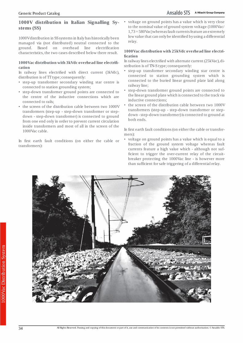
1000V distribution in SS systems in Italy has historically beenmanaged via (not distributed) neutral connected to theground. Based on overhead line electrificationcharacteristics, the two cases described below there result.
1000Vac distribution with 3kVdc overhead line electrifi-cationIn railway lines electrified with direct current (3kVdc),distribution is of TT type; consequently:• step-up transformer secondary winding star centre is
connected to station grounding system;• step-down transformer ground points are connected to
the centre of the inductive connections which areconnected to rails;
• the screen of the distribution cable between two 1000Vtransformers (step-up - step-down transformer or step-down - step-down transformer) is connected to groundfrom one end only in order to prevent current circulationinside transformers and most of all in the screen of the1000Vac cable.
In first earth fault conditions (on either the cable ortransformers):
• voltage on ground points has a value which is very closeto the nominal value of ground system voltage (1000Vac/1,73 = 580Vac) whereas fault currents feature an extremelylow value that can only be identified by using a differentialrelay.
1000Vac distribution with 25kVdc overhead line electri-ficationIn railway lines electrified with alternate current (25kVac), di-stribution is of TN-S type; consequently:• step-up transformer secondary winding star centre is
connected to station grounding system which isconnected to the buried linear ground plate laid alongrailway line;
• step-down transformer ground points are connected tothe linear ground plate which is connected to the track viainductive connections;
• the screen of the distribution cable between two 1000Vtransformers (step-up - step-down transformer or step-down - step-down transformer) is connected to ground atboth ends.
In first earth fault conditions (on either the cable or transfor-mers):• voltage on ground points has a value which is equal to a
fraction of the ground system voltage whereas faultcurrents feature a high value which - although not suf-ficient to trigger the over-current relay of the circuit-breaker protecting the 1000Vac line - is however morethan sufficient for safe triggering of a differential relay.
34 All Rights Reserved. Passing and copying of this document or part of it, use and communication of its contents is not permitted without authorization. © Ansaldo STS.
Power Supplies and Converters
1000
Vac
Dis
trib
utio
n Sy
stem
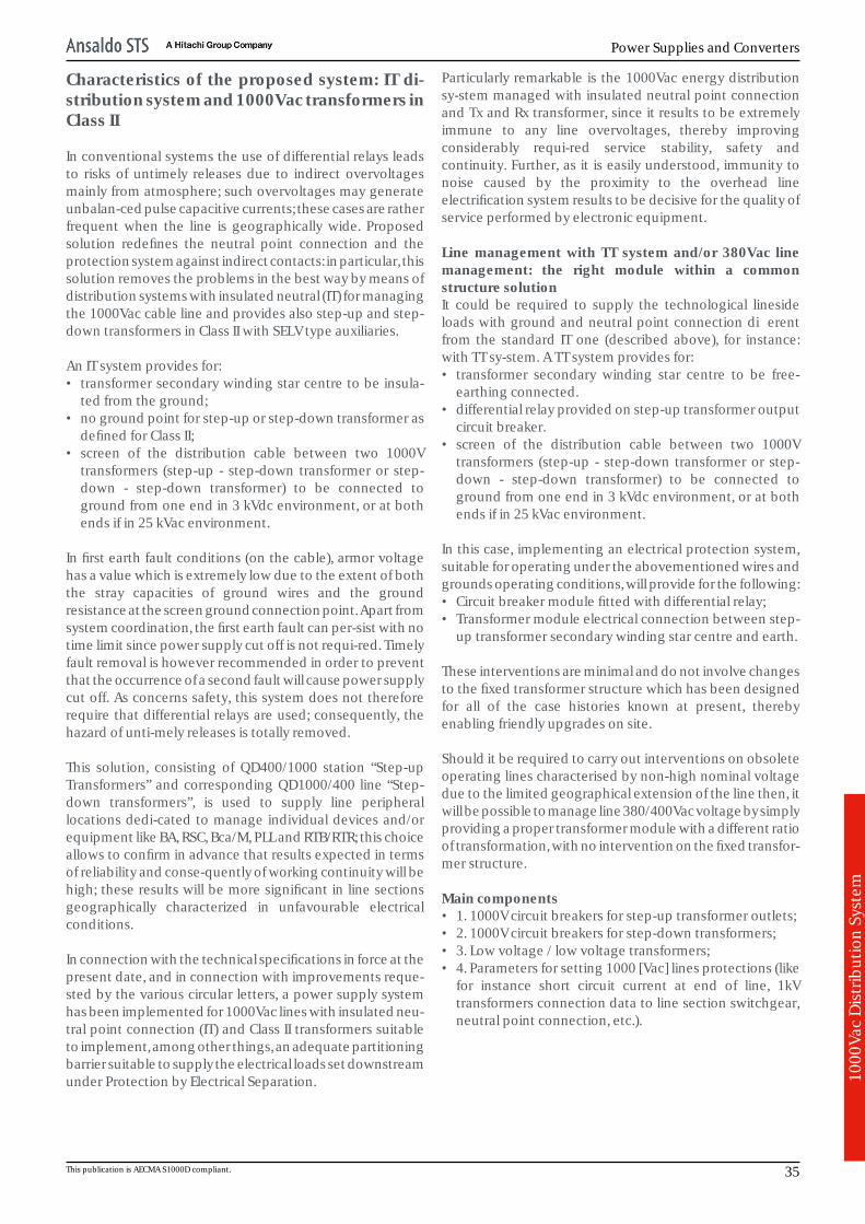
Characteristics of the proposed system: IT di-stribution system and 1000Vac transformers inClass II
In conventional systems the use of differential relays leadsto risks of untimely releases due to indirect overvoltagesmainly from atmosphere; such overvoltages may generateunbalan-ced pulse capacitive currents; these cases are ratherfrequent when the line is geographically wide. Proposedsolution redefines the neutral point connection and theprotection system against indirect contacts: in particular, thissolution removes the problems in the best way by means ofdistribution systems with insulated neutral (IT) for managingthe 1000Vac cable line and provides also step-up and step-down transformers in Class II with SELV type auxiliaries.
An IT system provides for:• transformer secondary winding star centre to be insula-
ted from the ground;• no ground point for step-up or step-down transformer as
defined for Class II;• screen of the distribution cable between two 1000V
transformers (step-up - step-down transformer or step-down - step-down transformer) to be connected toground from one end in 3 kVdc environment, or at bothends if in 25 kVac environment.
In first earth fault conditions (on the cable), armor voltagehas a value which is extremely low due to the extent of boththe stray capacities of ground wires and the groundresistance at the screen ground connection point. Apart fromsystem coordination, the first earth fault can per-sist with notime limit since power supply cut off is not requi-red. Timelyfault removal is however recommended in order to preventthat the occurrence of a second fault will cause power supplycut off. As concerns safety, this system does not thereforerequire that differential relays are used; consequently, thehazard of unti-mely releases is totally removed.
This solution, consisting of QD400/1000 station “Step-upTransformers” and corresponding QD1000/400 line “Step-down transformers”, is used to supply line peripherallocations dedi-cated to manage individual devices and/orequipment like BA, RSC, Bca/M, PLL and RTB/RTR; this choiceallows to confirm in advance that results expected in termsof reliability and conse-quently of working continuity will behigh; these results will be more significant in line sectionsgeographically characterized in unfavourable electricalconditions.
In connection with the technical specifications in force at thepresent date, and in connection with improvements reque-sted by the various circular letters, a power supply systemhas been implemented for 1000Vac lines with insulated neu-tral point connection (IT) and Class II transformers suitableto implement, among other things, an adequate partitioningbarrier suitable to supply the electrical loads set downstreamunder Protection by Electrical Separation.
Particularly remarkable is the 1000Vac energy distributionsy-stem managed with insulated neutral point connectionand Tx and Rx transformer, since it results to be extremelyimmune to any line overvoltages, thereby improvingconsiderably requi-red service stability, safety andcontinuity. Further, as it is easily understood, immunity tonoise caused by the proximity to the overhead lineelectrification system results to be decisive for the quality ofservice performed by electronic equipment.
Line management with TT system and/or 380Vac linemanagement: the right module within a commonstructure solutionIt could be required to supply the technological linesideloads with ground and neutral point connection differentfrom the standard IT one (described above), for instance:with TT sy-stem. A TT system provides for:• transformer secondary winding star centre to be free-
earthing connected.• differential relay provided on step-up transformer output
circuit breaker.• screen of the distribution cable between two 1000V
transformers (step-up - step-down transformer or step-down - step-down transformer) to be connected toground from one end in 3 kVdc environment, or at bothends if in 25 kVac environment.
In this case, implementing an electrical protection system,suitable for operating under the abovementioned wires andgrounds operating conditions, will provide for the following:• Circuit breaker module fitted with differential relay;• Transformer module electrical connection between step-
up transformer secondary winding star centre and earth.
These interventions are minimal and do not involve changesto the fixed transformer structure which has been designedfor all of the case histories known at present, therebyenabling friendly upgrades on site.
Should it be required to carry out interventions on obsoleteoperating lines characterised by non-high nominal voltagedue to the limited geographical extension of the line then, itwill be possible to manage line 380/400Vac voltage by simplyproviding a proper transformer module with a different ratioof transformation, with no intervention on the fixed transfor-mer structure.
Main components• 1. 1000V circuit breakers for step-up transformer outlets;• 2. 1000V circuit breakers for step-down transformers;• 3. Low voltage / low voltage transformers;• 4. Parameters for setting 1000 [Vac] lines protections (like
for instance short circuit current at end of line, 1kVtransformers connection data to line section switchgear,neutral point connection, etc.).
This publication is AECMA S1000D compliant. 35
Generic Product Catalog
1000
Vac
Dis
trib
utio
n Sy
stem
1000Vac line drive and control system
The implemented 1000Vac line drive and controltechnological system is a real added value for this system ofelectrical energy distribution to technological linesideequipment and devices. The PLC installed in step-downtransformers acts as concen-trator of the relevant diagnosticinfo and data and controls the local logic functions. The samefunction is run also by the PLCs installed in step-uptransformers which in addition are charged with thefollowing roles: line manager, data concentrator of all therelevant transformers, diagnostic front-end to remotesupervision system (Scada D&M). Communicationarchitecture between PLCs provides TCP-IP (Modbus)network connection to be implemented in optical fibre(preferably) according to overvoltage protection mattersissued by the latest RFI directions.
The drive and control system implements several functionsamong which the main ones are the following:
• displaying the 1000Vac line energization state anddiagnostic details of each transformer connected to it, onthe HMI terminal provided on step-up transformers;
• executing single remote commands;• managing insulation control between active wires and
ground of the 1000Vac line (if the line is managed withneutral point connection and IT type grounds);
• option to run troubleshooting on 1000Vac line via remotecontrol manual procedure or, via automatic proceduremanaged autonomously by the step-up transformer PLCwhich will identify the line section in failure and willprovide to run automatic line reconfiguration isolating thefailing section and supplying the step-down transformersfrom line sections not involved in the failure. Theidentification procedure of the section in failure and theconsequent reconfiguration of the circuit will beperformed after Operator’s confirmation if the 1000Vacline is managed with neutral point connection and IT typegrounds or, immediately after the failure which has causedits powering-off in case the line is managed with neutralpoint connection and TT type grounds;
• automatic line reconfiguration when a live step-uptransformer is powered off by its power supply system (setupstream) in order to allow prompt supplying to thetechnological lineside equipment and devices by theother step-up transformer, thereby restoring all therelevant functions;
• smart line management suitable to avoid unrequiredcircuit closing via interlocks on motorized commands andpreventing undue manual commands directly on circuitbreakers in order to safeguard power supply continuity;
• Integrated Energy Management (GEI) of line loads suitableto control supplying of non priority electrical loads (likefor instance HVAC) in “time-sharing” thereby reducing theelectrical load over the line in case of need;
• management of the power-off control of thosetechnological equipment and devices that allow for thispossibility for a correct “shut-down” before the intentionalreconfiguration of the line, and management of thepower-on control of the abovementioned equipment anddevices once the reconfiguration procedure is over;
• management of the insulation control after the step-downtransformer, also in discontinuous control mode, andmonitoring of main electrical parameters if choosingpower supply of downstream loads with wires andgrounds in Electrical Separation operation.
36 All Rights Reserved. Passing and copying of this document or part of it, use and communication of its contents is not permitted without authorization. © Ansaldo STS.
Power Supplies and Converters
1000
Vac
Dis
trib
utio
n Sy
stem
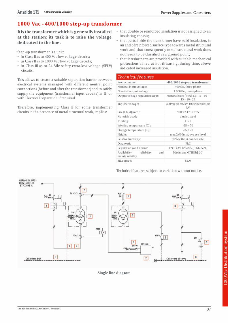
1000 Vac - 400/1000 step-up transformerIt is the transformer which is generally installedat the station; its task is to raise the voltagededicated to the line.
Step-up transformer is a unit:• in Class II as to 400 Vac low voltage circuits;• in Class II as to 1000 Vac low voltage circuits;• in Class III as to 24 Vdc safety extra-low voltage (SELV)
circuits.
This allows to create a suitable separation barrier betweenelectrical systems managed with different neutral pointconnections (before and after the transformer) and to safelysupply the equipment (transformer input circuits) in IT, orwith Electrical Separation if required.
Therefore, implementing Class II for some transformercircuits in the presence of metal structural work, implies:
• that double or reinforced insulation is not assigned to aninsulating chassis;
• that parts inside the transformer have solid insulation, inair and of reinforced surface type towards metal structuralwork and that consequently metal structural work doesnot result to be classified as a ground point;
• that interior parts are provided with suitable mechanicalprotections aimed at not thwarting, during time, aboveindicated increased insulation.
Technical featuresProduct name: 400/1000 step-up transformerNominal input voltage: 400Vac, three-phaseNominal output voltage: 1.000Vac, three-phaseOutput voltage regulation steps: Nominal sizes [kVA]: 1,5 – 5 – 10 –
15 – 20 - 25Impulse voltage: 400Vac side: 6 kV, 1000Vac side: 20
kVSize [l, h, d] [mm]: 900 x 2.170 x 785Materials used: aluzinc steelIP rating: IP 21Working temperature [C] : -25 ÷ 70Storage temperature [ C] : -25 ÷ 70Height: max 2,000m above sea levelRelative humidity: 90% without condensateDiagnostic PLCRegulations and norms: EN61439, EN60950, EN60529.Availability, reliability andmaintainability
Maximum MTTR [h]: 30’
SIL degree: SIL 0
Technical features subject to variation without notice.
Single line diagram
This publication is AECMA S1000D compliant. 37

Generic Product Catalog
1000
Vac
Dis
trib
utio
n Sy
stem
400/1000 step-up transformer
1.24Vdc auxiliary circuit-breaker module2.Diagnostic (PLC), control and HMI module3.1000Vac circuit-breaker (after transformer)4.400Vac circuit-breaker (at transformer input)5.Ground switch disconnector6.Voltage transformer and polling contactor7.400/1000Vac three-phase step-up transformer8.Terminal block compartment for line cable connection
38 All Rights Reserved. Passing and copying of this document or part of it, use and communication of its contents is not permitted without authorization. © Ansaldo STS.
Power Supplies and Converters
1000
Vac
Dis
trib
utio
n Sy
stem
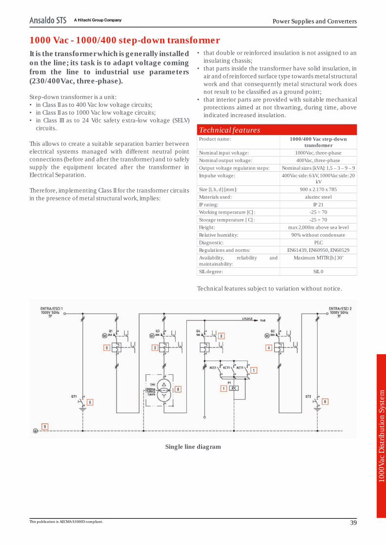
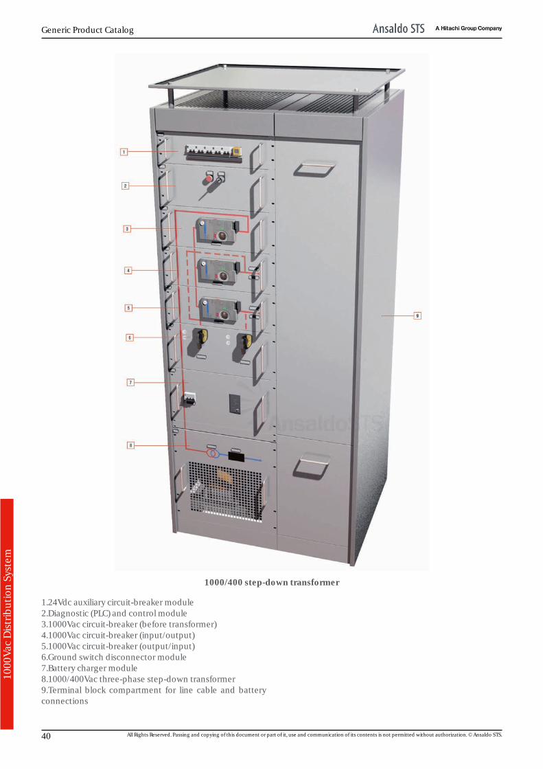
1000 Vac - 1000/400 step-down transformerIt is the transformer which is generally installedon the line; its task is to adapt voltage comingfrom the line to industrial use parameters(230/400Vac, three-phase).
Step-down transformer is a unit:• in Class II as to 400 Vac low voltage circuits;• in Class II as to 1000 Vac low voltage circuits;• in Class III as to 24 Vdc safety extra-low voltage (SELV)
circuits.
This allows to create a suitable separation barrier betweenelectrical systems managed with different neutral pointconnections (before and after the transformer) and to safelysupply the equipment located after the transformer inElectrical Separation.
Therefore, implementing Class II for the transformer circuitsin the presence of metal structural work, implies:
• that double or reinforced insulation is not assigned to aninsulating chassis;
• that parts inside the transformer have solid insulation, inair and of reinforced surface type towards metal structuralwork and that consequently metal structural work doesnot result to be classified as a ground point;
• that interior parts are provided with suitable mechanicalprotections aimed at not thwarting, during time, aboveindicated increased insulation.
Technical featuresProduct name: 1000/400 Vac step-down
transformerNominal input voltage: 1000Vac, three-phaseNominal output voltage: 400Vac, three-phaseOutput voltage regulation steps: Nominal sizes [kVA]: 1,5 – 3 – 9 – 9Impulse voltage: 400Vac side: 6 kV, 1000Vac side: 20
kVSize [l, h, d] [mm]: 900 x 2.170 x 785Materials used: aluzinc steelIP rating: IP 21Working temperature [C] : -25 ÷ 70Storage temperature [ C] : -25 ÷ 70Height: max 2,000m above sea levelRelative humidity: 90% without condensateDiagnostic: PLCRegulations and norms: EN61439, EN60950, EN60529Availability, reliability andmaintainability:
Maximum MTTR [h] 30’
SIL degree: SIL 0
Technical features subject to variation without notice.
Single line diagram
This publication is AECMA S1000D compliant. 39
Generic Product Catalog
1000
Vac
Dis
trib
utio
n Sy
stem
1000/400 step-down transformer
1.24Vdc auxiliary circuit-breaker module2.Diagnostic (PLC) and control module3.1000Vac circuit-breaker (before transformer)4.1000Vac circuit-breaker (input/output)5.1000Vac circuit-breaker (output/input)6.Ground switch disconnector module7.Battery charger module8.1000/400Vac three-phase step-down transformer9.Terminal block compartment for line cable and batteryconnections
40 All Rights Reserved. Passing and copying of this document or part of it, use and communication of its contents is not permitted without authorization. © Ansaldo STS.
Power Supplies and Converters
DC/
AC
Conv
erte
r
DC/AC ConverterConstruction features"Power supply systems with static converters" are suitablefor outdoor use in places located near the track. The rack andall the internal metallic accessories, including screws andnuts, are AISI304 stainless steel. Racks with max 6kVA power shall be installed on pole.Racks with power between 6kVA and max 200kVA shall beinstalled at ground level on a cement bedplate withconnection cable inlet from the bottom and/or from the top.Power cord features 50kV isolation at 50 Hz and 125 kV pulseand is fitted with a metallic screen of at least 70nmq.Every device is fitted with proper anti-vibration systems.The protection class with doors closed is IP54.The protection class with open doors, for both the MT(medium voltage) and bt (low voltage) compartments, isIPXXB at least. MT/bt compartments can only be accessed after removingthe appropriate panels using the tools provided for thepurpose.Suitable warning signs shall be affixed on every removablepart that provides access to live components and/orenergizable components. FunctionsWhatever internal malfunctioning affecting the converter,including sectioning device, fuse and arrester, won't haveeffect on the continuity of the 3.6 kVdc power supply line.Connecting cable screen discharge (if any) to the dc line willtrigger the fuse. Fuse operation is monitored via the statuschange of an electric clean contact (fuse tripping) connectedto the terminal block. Automatic operating time is lower than 15 seconds fromwhen voltage will be present on the dc line, voltage can beregulated between 2200 and 3300 Vdc. Converter activation after manual or automatic disconnectormaking is subject to a local/remote switch: in local it will beof the manual type whereas in remote it will be of theautomatic type. Selectable (local/remote) activation control/procedure hasbeen provided. Exceeding the frequency range and/or the output voltagewill result in converter shutdown. In case of power absorption > 100% than rated power, theconverter will limit current to the max admitted value. In case of output short circuit, a protection circuit forelectronic components will limit the current to 150% peak ofthe nominal current; should this condition last, an outputautomatic breaker will cut-in. Connection continuity to CDTE and to CPTE is monitored.
Energy quantitiesSupplied energy quantities feature one minute samplingrate and are stored in a memory which can be consulted fora thirty-years period. Functions towards the outsideIt has been provided the transmission via fiber optic terminal,supported by standard FS protocol, of controls anddiagnostic data concerning:- local/remote service selection- control and monitoring converter on/off- on/off indication- power-on number counter- Counter of the number of automatic shutdowns due toinput overvoltage and undervoltage- Permanent monitoring of the connection integrity of thenegative reference wire and issue of the relevant alarm fornegative connection break.- Alarm for current passing through power cord screenconnected to the TE protection circuit.- MT fuse tripping indication .- Disconnector on/off state.- Input voltage measure.- Internal temperature on at least two different stages of thepole-installed device and four on ground-installed devices.. Ancillary equipmentSystems come with the following accessories: Pole-type version:- Lower support complete with bolts for universal fasteningon poles of the "M" type and "LS" type (collars excluded).- Upper support complete with bolts for universal fasteningon poles of the "M" type and "LS" type (collars excluded).- Single-pole disconnector with MT fuse and fuse holder,complete with hand winch with transmission operation fromthe bottom (operating rod excluded). Ground-type version:- Single-pole disconnector with MT fuse and fuse holder,complete with hand winch with transmission operation fromthe bottom (operating rod excluded).- MT cable, 10 meters. CDTE and CPTE connection continuity checksConnection or CDTE or CPTE lack of continuity will result inconverter locking within max 100 ms.Converter is reconnected following the sequence below:1. Open the disconnector on MT side2. Reset CDPE or CPTE connection or connections3. Close the disconnector on MT side. Rack structureRack structure is in press-bent sheet plate with first-class,15/10 nm thickness, AISI 304 rolled steel sections, paintedexternally with RAL 7044 color. Optional accessoriesMT disconnector remote control motorization.
This publication is AECMA S1000D compliant. 41

Generic Product Catalog
DC/
AC
Conv
erte
r
Electrical characteristics:- 132 Vdc external power supply- Remote local selector- Electrical/mechanical lock of the two positions.- Extraction key on open position from local.- Local opening/closing both electrical and manual. Mechanical characteristics:- Point machine preset for both piling installation andinstallation on "M" and "LS" poles- Steel structure, 15/10 thickness- External painting RAL 7044.- Door with key-lock, FS standardized type.
42 All Rights Reserved. Passing and copying of this document or part of it, use and communication of its contents is not permitted without authorization. © Ansaldo STS.

Power Supplies and Converters
DC/
AC
Conv
erte
r
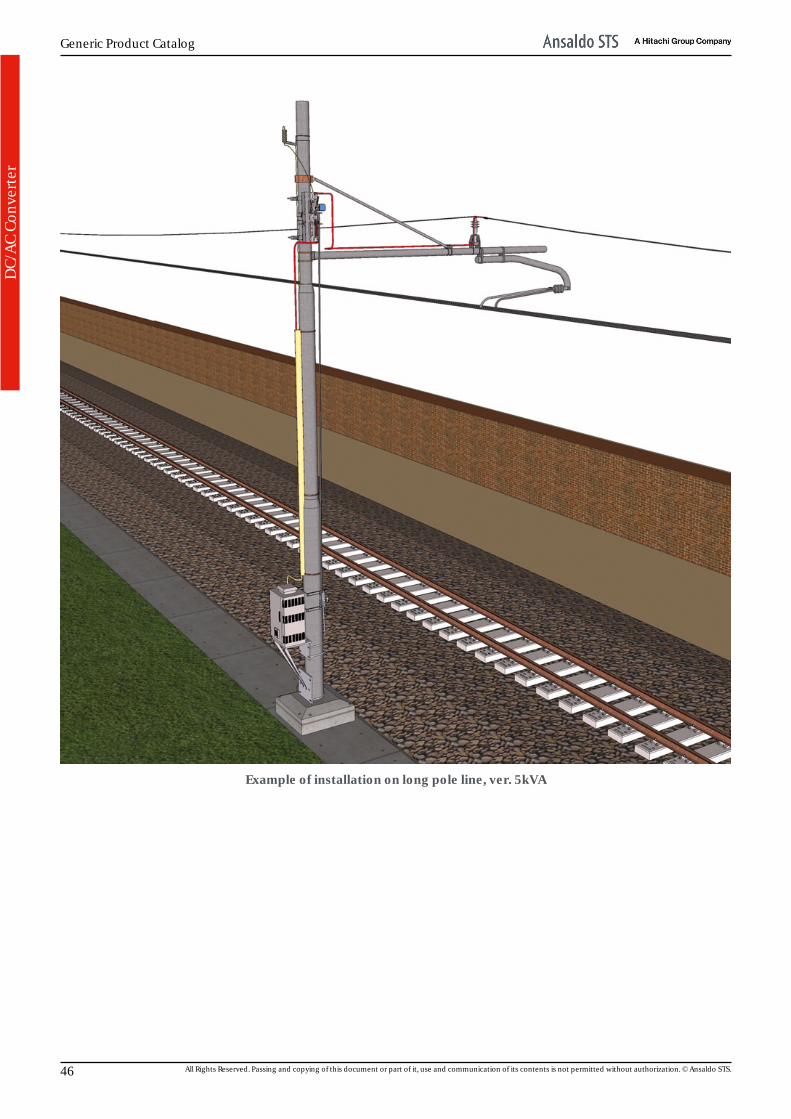
5 kVA DC/AC ConverterThe 5 kVA version, to be pole-installed and to be used for powering signaling huts, TxD systemshelters located along the line, line lighting systems for TE system maintenance, tunnel lightingsystems, points heating BTS systems for small-layout stations, etc.
This publication is AECMA S1000D compliant. 43

Generic Product Catalog
DC/
AC
Conv
erte
r
General FeaturesPart number: ---Format:Size [l, h, d] [mm]:Front Panel:
---700, 1.400, 550
---MTBF [h]: > 70.000 load max.Weight [g]: 230.000Front panel color: RAL7044Working temperature [°C]:Storage temperature [°C]:Vibrations:Altitude[m]:Relative humidity:
-25 ÷ 70-25 ÷ 70
---< 2.000
95% (@ 30° C) non-condensingComposition: ---Obsolescence:HW revision:SW revision:SW file:Naming:
no------------
Certifications and conformity: CEI EN 50122-1; CEI 64-8; CEI EN 50121-1;CEI EN 50119; CEI 20-13; CEI 20-38; IS 365/ed.2008; IS 402 A ed.2000; IS 728 ed.2000.
Technical FeaturesPower supplyPower supply system nominal voltage [kVdc]: 3,6Max permanent voltage [kVdc]: 3,6Max non-permanent voltage Umax2 (t < 5') [kVdc]: 3,9Max transient no-load voltage Umax3 (t = 20 ms) [kVdc]: 5,2OutputSingle-phase/three-phase output voltage [Vac]: 230 ± 1%Frequency [Hz]: 50 ± 1%;Ripple: 125% max. per 5'Rack characteristicsPaint flatness degree: < 25 glossPaint thickness [μm]: 70 typ. (40 min.)Paint type: Polyester powderProtectionsIn the event of power absorption > 100% than nominal power, converterwill limit current to the max admitted value.In the event of output short-circuit, there is a circuit fitted which protectsthe electronic components by limiting current to 150% nominal currentpeak; output automatic switch is also fitted.Ground isolation voltage monitoring with safety circuit intervention toprevent dangerous accidental contacts. Remote diagnostics via fiber optic link; transmission via fiber opticterminal supported by FSIEC870.5 standard protocol of diagnosticcontrols and data concerning:1. On/Off2. Running hours3. Power-on number4. Number of shutdowns due to input overvoltage/undervoltage5. Ground failure alarm6. Input voltage measurement7. Output Power measurement8. Inner temperature into the two stages9. Permanent control of the integrity of the connection of the negativereference conductor10. Local/remote operating choice11. On/off warning12. Fuse release13. On/off sectioning switch stateMTTR: < 30'
Technical features subject to variation without notice.
Schematic
44 All Rights Reserved. Passing and copying of this document or part of it, use and communication of its contents is not permitted without authorization. © Ansaldo STS.
Power Supplies and Converters
DC/
AC
Conv
erte
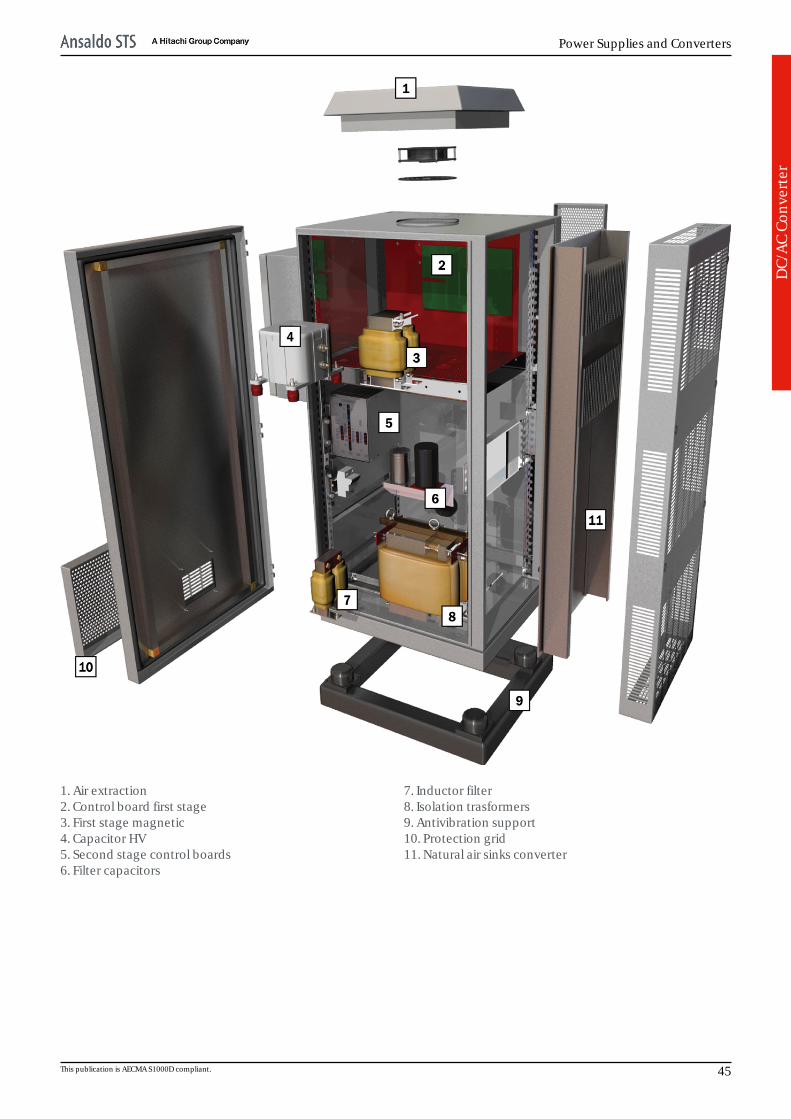
r1. Air extraction2. Control board first stage3. First stage magnetic4. Capacitor HV5. Second stage control boards6. Filter capacitors
7. Inductor filter8. Isolation trasformers9. Antivibration support10. Protection grid11. Natural air sinks converter
This publication is AECMA S1000D compliant. 45
Generic Product Catalog
DC/
AC
Conv
erte
r
Example of installation on long pole line, ver. 5kVA
46 All Rights Reserved. Passing and copying of this document or part of it, use and communication of its contents is not permitted without authorization. © Ansaldo STS.
Power Supplies and Converters
DC/
AC
Conv
erte
r
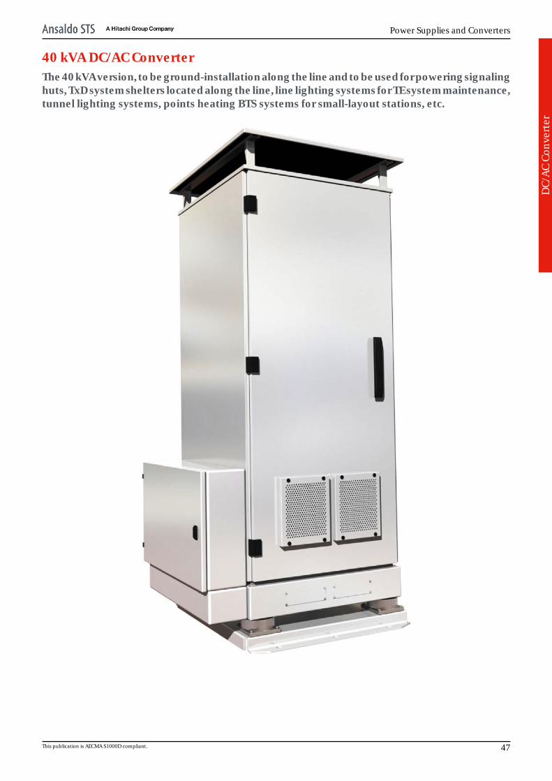
40 kVA DC/AC ConverterThe 40 kVA version, to be ground-installation along the line and to be used for powering signalinghuts, TxD system shelters located along the line, line lighting systems for TE system maintenance,tunnel lighting systems, points heating BTS systems for small-layout stations, etc.
This publication is AECMA S1000D compliant. 47
Generic Product Catalog
DC/
AC
Conv
erte
r
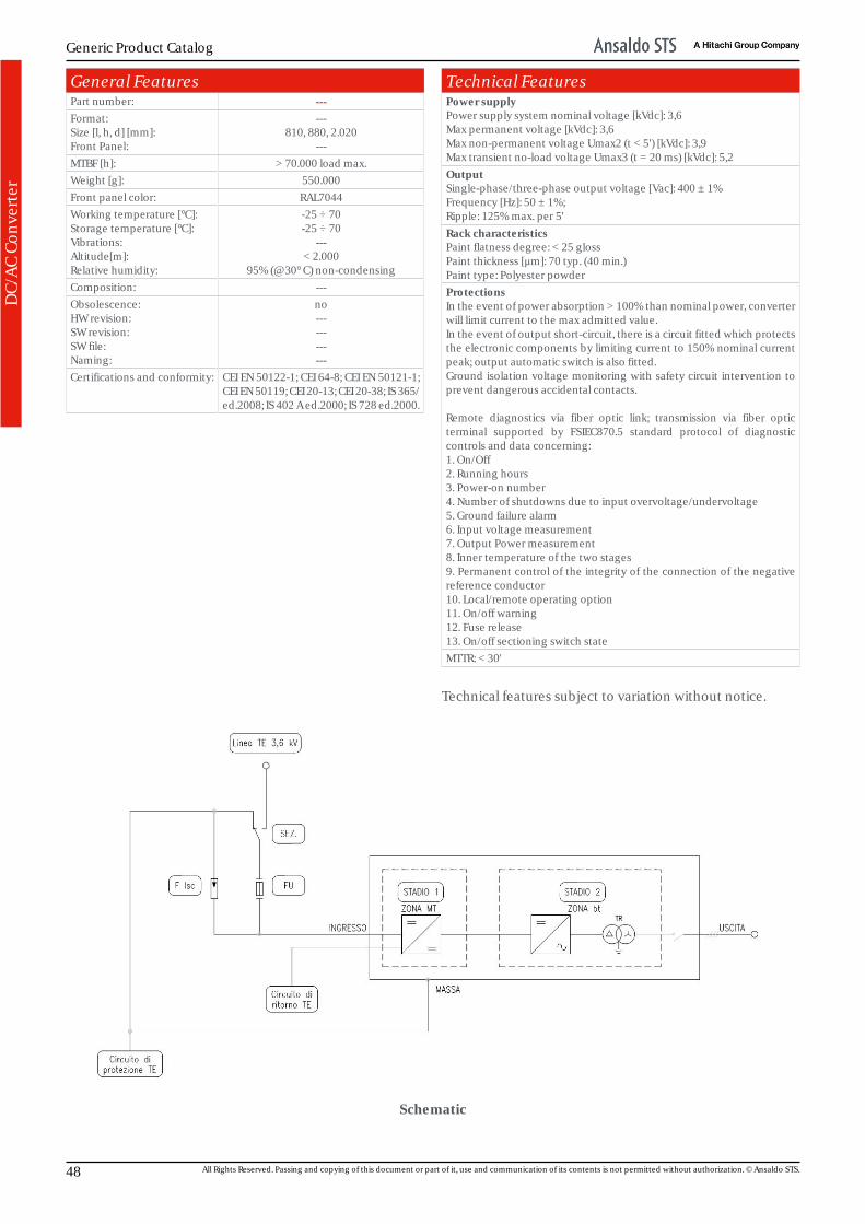
General FeaturesPart number: ---Format:Size [l, h, d] [mm]:Front Panel:
---810, 880, 2.020
---MTBF [h]: > 70.000 load max.Weight [g]: 550.000Front panel color: RAL7044Working temperature [°C]:Storage temperature [°C]:Vibrations:Altitude[m]:Relative humidity:
-25 ÷ 70-25 ÷ 70
---< 2.000
95% (@ 30° C) non-condensingComposition: ---Obsolescence:HW revision:SW revision:SW file:Naming:
no------------
Certifications and conformity: CEI EN 50122-1; CEI 64-8; CEI EN 50121-1;CEI EN 50119; CEI 20-13; CEI 20-38; IS 365/ed.2008; IS 402 A ed.2000; IS 728 ed.2000.
Technical FeaturesPower supplyPower supply system nominal voltage [kVdc]: 3,6Max permanent voltage [kVdc]: 3,6Max non-permanent voltage Umax2 (t < 5') [kVdc]: 3,9Max transient no-load voltage Umax3 (t = 20 ms) [kVdc]: 5,2OutputSingle-phase/three-phase output voltage [Vac]: 400 ± 1%Frequency [Hz]: 50 ± 1%;Ripple: 125% max. per 5'Rack characteristicsPaint flatness degree: < 25 glossPaint thickness [μm]: 70 typ. (40 min.)Paint type: Polyester powderProtectionsIn the event of power absorption > 100% than nominal power, converterwill limit current to the max admitted value.In the event of output short-circuit, there is a circuit fitted which protectsthe electronic components by limiting current to 150% nominal currentpeak; output automatic switch is also fitted.Ground isolation voltage monitoring with safety circuit intervention toprevent dangerous accidental contacts. Remote diagnostics via fiber optic link; transmission via fiber opticterminal supported by FSIEC870.5 standard protocol of diagnosticcontrols and data concerning:1. On/Off2. Running hours3. Power-on number4. Number of shutdowns due to input overvoltage/undervoltage5. Ground failure alarm6. Input voltage measurement7. Output Power measurement8. Inner temperature of the two stages9. Permanent control of the integrity of the connection of the negativereference conductor10. Local/remote operating option11. On/off warning12. Fuse release13. On/off sectioning switch stateMTTR: < 30'
Technical features subject to variation without notice.
Schematic
48 All Rights Reserved. Passing and copying of this document or part of it, use and communication of its contents is not permitted without authorization. © Ansaldo STS.
Power Supplies and Converters
DC/
AC
Conv
erte
r
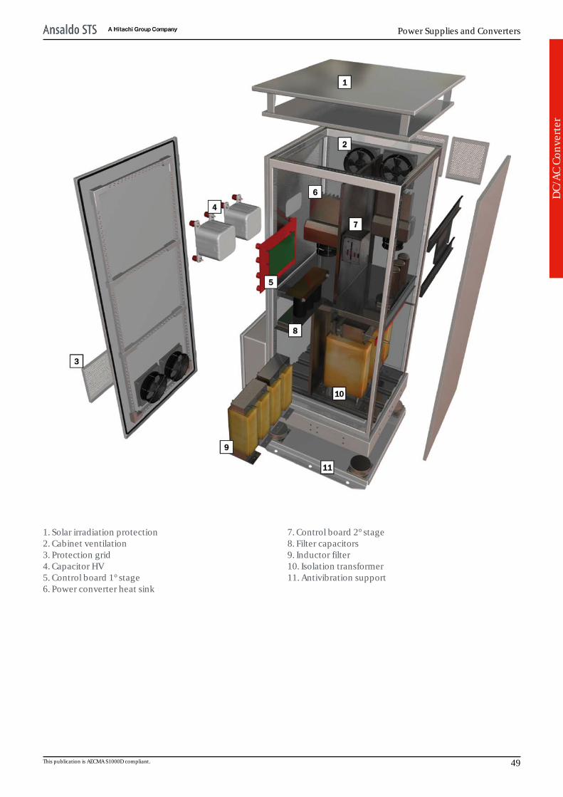
1. Solar irradiation protection2. Cabinet ventilation3. Protection grid4. Capacitor HV5. Control board 1° stage6. Power converter heat sink
7. Control board 2° stage8. Filter capacitors9. Inductor filter10. Isolation transformer11. Antivibration support
This publication is AECMA S1000D compliant. 49

Generic Product Catalog
DC/
AC
Conv
erte
r
Example of ground-installation along the line, ver. 40 kVA
50 All Rights Reserved. Passing and copying of this document or part of it, use and communication of its contents is not permitted without authorization. © Ansaldo STS.
Power Supplies and Converters
Spar
k ga
p su
rge
arre
ster
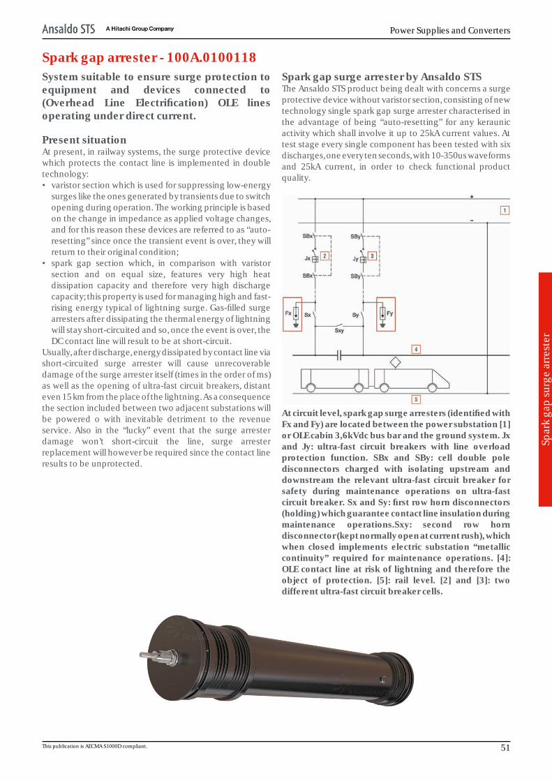
Spark gap arrester - 100A.0100118System suitable to ensure surge protection toequipment and devices connected to(Overhead Line Electrification) OLE linesoperating under direct current.
Present situationAt present, in railway systems, the surge protective devicewhich protects the contact line is implemented in doubletechnology:• varistor section which is used for suppressing low-energy
surges like the ones generated by transients due to switchopening during operation. The working principle is basedon the change in impedance as applied voltage changes,and for this reason these devices are referred to as “auto-resetting” since once the transient event is over, they willreturn to their original condition;
• spark gap section which, in comparison with varistorsection and on equal size, features very high heatdissipation capacity and therefore very high dischargecapacity; this property is used for managing high and fast-rising energy typical of lightning surge. Gas-filled surgearresters after dissipating the thermal energy of lightningwill stay short-circuited and so, once the event is over, theDC contact line will result to be at short-circuit.
Usually, after discharge, energy dissipated by contact line viashort-circuited surge arrester will cause unrecoverabledamage of the surge arrester itself (times in the order of ms)as well as the opening of ultra-fast circuit breakers, distanteven 15 km from the place of the lightning. As a consequencethe section included between two adjacent substations willbe powered o with inevitable detriment to the revenueservice. Also in the “lucky” event that the surge arresterdamage won’t short-circuit the line, surge arresterreplacement will however be required since the contact lineresults to be unprotected.
Spark gap surge arrester by Ansaldo STSThe Ansaldo STS product being dealt with concerns a surgeprotective device without varistor section, consisting of newtechnology single spark gap surge arrester characterised inthe advantage of being “auto-resetting” for any keraunicactivity which shall involve it up to 25kA current values. Attest stage every single component has been tested with sixdischarges, one every ten seconds, with 10-350us waveformsand 25kA current, in order to check functional productquality.
At circuit level, spark gap surge arresters (identified withFx and Fy) are located between the power substation [1]or OLE cabin 3,6kVdc bus bar and the ground system. Jxand Jy: ultra-fast circuit breakers with line overloadprotection function. SBx and SBy: cell double poledisconnectors charged with isolating upstream anddownstream the relevant ultra-fast circuit breaker forsafety during maintenance operations on ultra-fastcircuit breaker. Sx and Sy: first row horn disconnectors(holding) which guarantee contact line insulation duringmaintenance operations.Sxy: second row horndisconnector (kept normally open at current rush), whichwhen closed implements electric substation “metalliccontinuity” required for maintenance operations. [4]:OLE contact line at risk of lightning and therefore theobject of protection. [5]: rail level. [2] and [3]: twodifferent ultra-fast circuit breaker cells.
This publication is AECMA S1000D compliant. 51
Generic Product Catalog
Spar
k ga
p su
rge
arre
ster
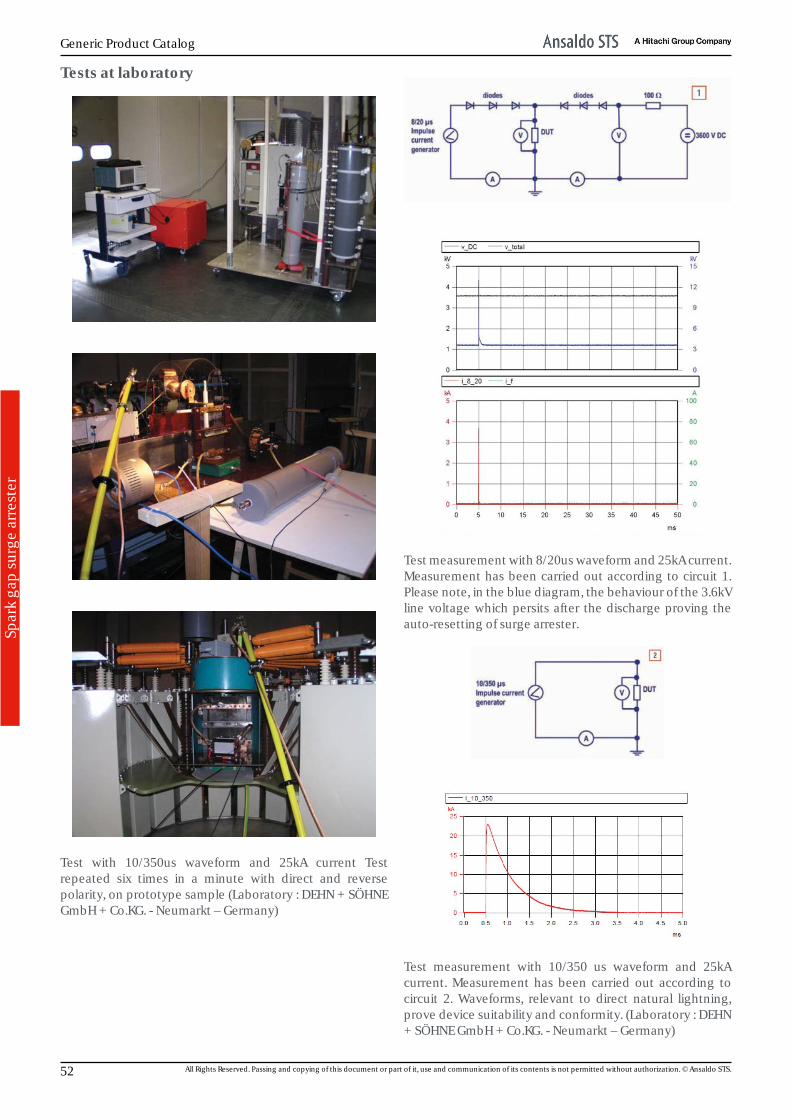
Tests at laboratory
Test with 10/350us waveform and 25kA current Testrepeated six times in a minute with direct and reversepolarity, on prototype sample (Laboratory : DEHN + SÖHNEGmbH + Co.KG. - Neumarkt – Germany)
Test measurement with 8/20us waveform and 25kA current.Measurement has been carried out according to circuit 1.Please note, in the blue diagram, the behaviour of the 3.6kVline voltage which persits after the discharge proving theauto-resetting of surge arrester.
Test measurement with 10/350 us waveform and 25kAcurrent. Measurement has been carried out according tocircuit 2. Waveforms, relevant to direct natural lightning,prove device suitability and conformity. (Laboratory : DEHN+ SÖHNE GmbH + Co.KG. - Neumarkt – Germany)
52 All Rights Reserved. Passing and copying of this document or part of it, use and communication of its contents is not permitted without authorization. © Ansaldo STS.

Power Supplies and Converters
Spar
k ga
p su
rge
arre
ster
Tests on site
Test installation at the railway station in Bibbiena (AR). Testing started on the month of October 2012. 1 - Traditionalsurge arrester 2 – Ansaldo STS’s surge arrester
Accessories
The SPD system can be installed with an associated devicereferred to as «impulse counter» which is provided forcounting the surge arrester reactions. The abovementioneddevice consists of the following components:• toroidal current sensor [1] specially designed for railway
applications and located on surge arrester groundconnection cable;
• impulse counting device [2] for counting impulses comingfrom the toroidal sensor and therefore the surge arresterreactions.
Impulse counter is installed on the post which mounts thesurge arrester, into an appropriate protecting container withproper protection rating (IP). If required, parameters read bythe abovementioned device can be remotized via datatransmission system.
This publication is AECMA S1000D compliant. 53
Generic Product Catalog
Spar
k ga
p su
rge
arre
ster
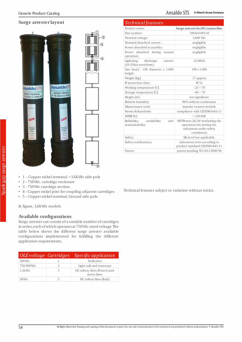
Surge arrester layout
• 1 – Copper nickel terminal. +3.6kVdc side pole• 2 - 750Vdc. cartridge enclosure• 3 - 750Vdc cartridge section.• 4 - Copper nickel joint for coupling adjacent cartridges• 5 – Copper nickel terminal. Ground side pole.
In figure, 3,6kVdc models
Available configurationsSurge arrester can consist of a variable number of cartridgesin series, each of which operates at 750Vdc rated voltage Thetable below shows the different surge arrester availableconfigurations implemented for fulfilling the differentapplication requirements.
OLE voltage Cartridges Specific application500Vdc 1 Trolleybus750/900Vdc 2 Light rails and tramways1,5kVdc 3 DC railway lines (France) and
metro lines3kVdc 5 DC railway lines (Italy)
Technical featuresProduct name: Surge arrester for DC contact linePart number: 100A.0100118Nominal voltage: 3.600 VdcNominal absorbed current : negligiblePower absorbed in standby: negligiblePower absorbed during normaloperation:
negligible
Lightning discharge current(10-350us waveform):
25.000A
Size [mm] : 190 diameter x 1.090height:
190 x 1.090
Weight [kg]: 17 approxIP protection class: IP 55Working temperature [C]: - 25 ÷ 70Storage temperature [C]: - 40 ÷ 70Height [m]: not significantRelative humidity: 90% without condensateMaintenance tools: impulse counter moduleNorms & Standards: compliance with CEI EN61643-11MTBF [h]: > 250.000Reliability, availability andmaintainability:
MTTR max. [h] 30’ (excluding theoperations for setting thesubsystem under safety
conditions)Safety: SIL level not applicable.Safety certifications: Laboratory tests according to
product standard CEI EN61643-11Patent: patent pending TO 2012 0000 94
Technical features subject to variation without notice.
54 All Rights Reserved. Passing and copying of this document or part of it, use and communication of its contents is not permitted without authorization. © Ansaldo STS.
Power Supplies and Converters
App
endi
x
Notes
This publication is AECMA S1000D compliant. 55

Generic Product Catalog
App
endi
x
56 All Rights Reserved. Passing and copying of this document or part of it, use and communication of its contents is not permitted without authorization. © Ansaldo STS.
Power Supplies and Converters
Trac
eabi
lity
of R
evie
ws
Table of Reviews
REV. DATE --- Prepared Approved Authorised Revision Reason00 17/07/2013 --- Alpestre A. Casazza A. --- ---
This publication is AECMA S1000D compliant. 57
Generic Product Catalog
58 All Rights Reserved. Passing and copying of this document or part of it, use and communication of its contents is not permitted without authorization. © Ansaldo STS.

© Property of Ansaldo STS SpA, all rights reserved.The copying, reproduction and use of this work in any formwhatsoever is forbidden without the written authorization ofAnsaldo STS SpA.

Ansaldo STS SpAVia Paolo Mantovani 3 – 516151 Genoa – Italywww.ansaldo-sts.com