Embed Size (px)
Citation preview
Translation of the original manual
Compensation Unit in X-, Y-, and Z-Direction AGE-S-XYZ 100 - 200
Assembly and Operating Manual
Superior Clamping and Gripping
www.comoso.com
Imprint
2 3.02|AGE-S-XYZ 100 - 200|en
Imprint
Copyright: This manual remains the copyrighted property of SCHUNK GmbH & Co. KG. It is solely supplied to our customers and operators of our products and forms part of the module. This documentation may not be duplicated or made accessible to third parties, in particu-lar competitive companies, without our prior permission.
Technical changes: We reserve the right to make alterations for the purpose of technical improvement.
Document number: 0389004
Edition: 3.02 |05/07/2013|en
© SCHUNK GmbH & Co. KG All rights reserved.
Dear customer,
congratulations on choosing a SCHUNK product. By choosing SCHUNK, you have opted for the highest precision, top quality and best service.
You are going to increase the process reliability of your production and achieve best machining results – to the customer's complete satisfaction.
SCHUNK products are inspiring.
Our detailed assembly and operation manual will support you.
Do you have further questions? You may contact us at any time – even after purchase.
Kindest Regards
Yours SCHUNK GmbH & Co. KG Spann- und Greiftechnik
Bahnhofstr. 106 – 134 D-74348 Lauffen/Neckar
Tel. +49-7133-103-2503 Fax +49-7133-103-2189
[email protected] www.schunk.com
www.comoso.com
Table of contents
3.02|AGE-S-XYZ 100 - 200|en 3
Table of contents
1 About this manual .................................................................................................... 4
1.1 Warnings ................................................................................................................... 4
1.1.1 Key words ...................................................................................................... 4
1.1.2 Symbols ......................................................................................................... 4
1.2 Applicable documents .............................................................................................. 4
2 Basic safety notes .................................................................................................... 5
2.1 Intended use ............................................................................................................. 5
2.2 Not intended use ...................................................................................................... 5
2.3 Environmental and operating conditions ................................................................. 5
2.4 Product safety........................................................................................................... 6
2.4.1 Protective equipment ................................................................................... 6
2.4.2 Constructional changes, attachments, or modifications .............................. 6
2.5 Personnel qualification ............................................................................................. 6
2.6 Using personal protective equipment ...................................................................... 7
2.7 Notes on particular risks ........................................................................................... 7
3 Warranty .................................................................................................................. 9
4 Scope of delivery ...................................................................................................... 9
5 Technical Data ......................................................................................................... 10
6 Mounting and commissioning .................................................................................. 11
6.1 Assembly ................................................................................................................. 11
6.2 air connection / media connection ........................................................................ 12
6.3 Mounting of the sensors ........................................................................................ 14
7 Troubleshooting ...................................................................................................... 19
7.1 Problem analysis ..................................................................................................... 19
8 Maintenance and care ............................................................................................. 19
8.1 Maintenance intervals ............................................................................................ 19
9 Assembly drawing ................................................................................................... 20
9.1 AGE-XYZ .................................................................................................................. 20
9.2 AGE-XY .................................................................................................................... 21
9.3 AGE-Z ...................................................................................................................... 22
10 Accessories kit ......................................................................................................... 23
11 Translation of original declaration of incorporation ................................................. 24
www.comoso.com
About this manual
4 3.02|AGE-S-XYZ 100 - 200|en
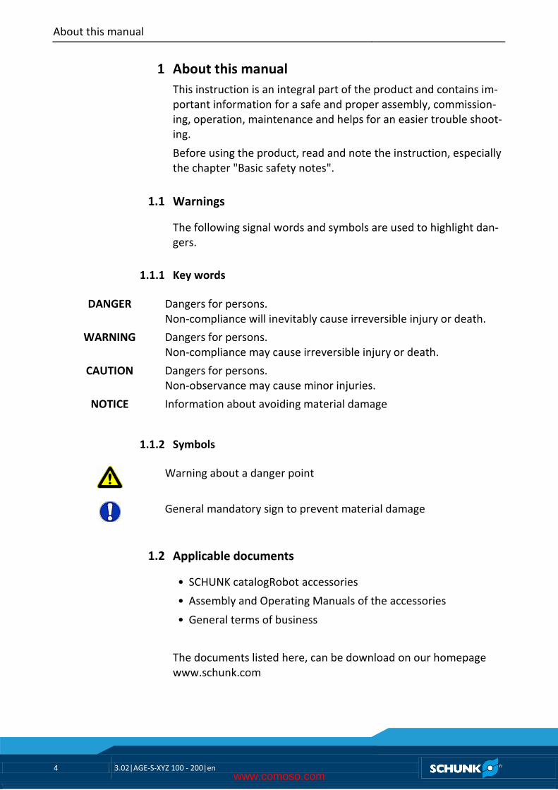
About this manual This instruction is an integral part of the product and contains im-portant information for a safe and proper assembly, commission-ing, operation, maintenance and helps for an easier trouble shoot-ing.
Before using the product, read and note the instruction, especially the chapter "Basic safety notes".
Warnings
The following signal words and symbols are used to highlight dan-gers.
Key words
DANGER Dangers for persons. Non-compliance will inevitably cause irreversible injury or death.
WARNING Dangers for persons. Non-compliance may cause irreversible injury or death.
CAUTION Dangers for persons. Non-observance may cause minor injuries.
NOTICE Information about avoiding material damage
Symbols
Warning about a danger point
General mandatory sign to prevent material damage
Applicable documents
• SCHUNK catalogRobot accessories
• Assembly and Operating Manuals of the accessories
• General terms of business
The documents listed here, can be download on our homepage www.schunk.com
1
1.1
1.1.1
1.1.2
1.2
www.comoso.com
Basic safety notes
3.02|AGE-S-XYZ 100 - 200|en 5
Basic safety notes
Intended use
The unit was designed for mechanical adjustment and storing a fixed positioning point of workpieces or objects.
The module is intended for installation in a machine/system. The requirements of the applicable guidelines must be observed and complied with.
The module may be used only in the context of its defined applica-tion parameters ( 5, Page 10).
To use this unit as intended, it is also essential to observe the technical data and installation and operation notes in this manual and to comply with the maintenance intervals.
Not intended use
It is not an intended use if the module is used, for example, as a pressing tool, stamping tool, lifting gear, guide for tools, cutting tool, clamping device or a drilling tool.
Environmental and operating conditions
• Ensure that the module and the top jaws are adequately di-mensioned according to the application
• Ensure that the environment is clean. Observe the mainten-ance and lubrication intervals "Maintenance intervals" ( 8.1, Page 19)
• Ensure that the environment is free of splashing water and va-pors, and also of abrasive dust and process dust. Excepted are modules that are designed especially for contaminated en-vironments.
2
2.1
2.2
2.3
www.comoso.com
Basic safety notes
6 3.02|AGE-S-XYZ 100 - 200|en
Product safety
Dangers arise from the module, if:
• the module is not used in accordance with its intended pur-pose.
• the module is not installed or maintained properly.
• the safety and installation notes are not observed.
Avoid any manner of working that may interfere with the function and operational safety of the module.
Wear protective equipment.
NOTE More information are contained in the relevant chapters.
Protective equipment
Provide protective equipment per EC Machinery Directive.
Constructional changes, attachments, or modifications
Additional drill holes, threads, or attachments that are not offered as accessories by SCHUNK may be attached only with permission of SCHUNK.
Personnel qualification
The assembly, initial commissioning, maintenance, and repair of the module may be performed only by trained specialist person-nel. Every person called upon by the operator to work on the module must have read and understood the complete assembly and operating manual, especially the chapter "Basic safety notes" ( 2, Page 5). This applies particularly to personnel only used oc-casionally, such as maintenance personnel.
2.4
2.4.1
2.4.2
2.5
www.comoso.com
Basic safety notes
3.02|AGE-S-XYZ 100 - 200|en 7
Using personal protective equipment
When using this product, observe the relevant industrial safety regulations and use the personal protective equipment (PPE) re-quired!
• Use protective gloves, safety shoes and safety goggles.
• Observe safe distances.
• Minimal safety requirements for the use of equipment.
Notes on particular risks
Generally valid:
• Remove the energy supplies before installation, modification, maintenance, or adjustment work.
• Make sure, that no residual energy remains in the system.
• Do not move parts by hand when the energy supply is con-nected.
• Do not reach into the open mechanism or the movement area of the module.
• Perform maintenance, modifications, and additions outside the danger zone.
• For all work, secure the unit against accidental operation.
• Take a precautionary approach by maintenance and disassem-bly.
• Only specially trained staff should disassemble the module.
2.6
2.7
www.comoso.com
Basic safety notes
8 3.02|AGE-S-XYZ 100 - 200|en
WARNING
Risk of injury when the machine/system moves unexpectedly due to failure of the energy supply or malfunction of the con-troller.
WARNING
Risk of injury from falling objects or module falling!
• Follow the assembly instructions.
• Provide protective equipment to prevent objects or the mod-ule from falling, such as processed workpieces, tools, chips, fragments, rejects.
WARNING
Risk of injury due to faulty actuation!
• Do not reach into the movement range of the module during start-up, modification or adjustment work.
• Observe the direction of rotation of the module when design-ing the actuation.
www.comoso.com
Scope of delivery
3.02|AGE-S-XYZ 100 - 200|en 9
Warranty The warranty is valid for 24 months from the delivery date to the production facility under the following conditions:
• Intended use in 1-shift operation
• Observe the mandatory maintenance and lubrication intervals
• Observe the environmental and operating conditions
Parts touching the work piece and wear parts are not part of the warranty.
Scope of delivery The scope of delivery includes:
• Compensation Unit in X-, Y-, and Z-Direction AGE-S-XYZ in the ordered model.
• Accessory pack
3
4
www.comoso.com
Technical Data
10 3.02|AGE-S-XYZ 100 - 200|en
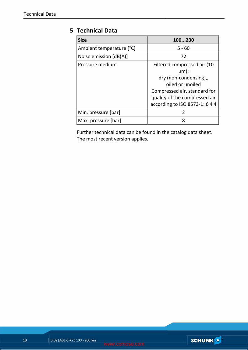
Technical Data
Size 100...200
Ambient temperature [°C] 5 - 60
Noise emission [dB(A)] 72
Pressure medium Filtered compressed air (10 μm):
dry (non-condensing),, oiled or unoiled
Compressed air, standard for quality of the compressed air according to ISO 8573-1: 6 4 4
Min. pressure [bar] 2
Max. pressure [bar] 8
Further technical data can be found in the catalog data sheet. The most recent version applies.
5
www.comoso.com
Mounting and commissioning
3.02|AGE-S-XYZ 100 - 200|en 11
Mounting and commissioning
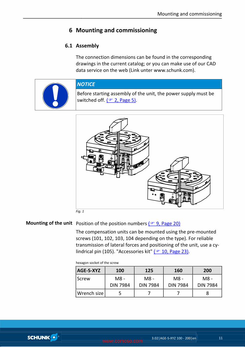
Assembly
The connection dimensions can be found in the corresponding drawings in the current catalog; or you can make use of our CAD data service on the web (Link unter www.schunk.com).
NOTICE
Before starting assembly of the unit, the power supply must be switched off. ( 2, Page 5).
Fig. 1
Position of the position numbers ( 9, Page 20)
The compensation units can be mounted using the pre-mounted screws (101, 102, 103, 104 depending on the type). For reliable transmission of lateral forces and positioning of the unit, use a cy-lindrical pin (105). "Accessories kit" ( 10, Page 23).
hexagon socket of the screw
AGE-S-XYZ 100 125 160 200
Screw M8 - DIN 7984
M8 - DIN 7984
M8 - DIN 7984
M8 - DIN 7984
Wrench size 5 7 7 8
6
6.1
Mounting of the unit
www.comoso.com
Mounting and commissioning
12 3.02|AGE-S-XYZ 100 - 200|en
The compensation units are equipped with interfaces in accor-dance with ISO/DIS 9409-1
Type Interface
AGE 100 ISO 9409-1-100-6-M8
AGE 125 ISO 9409-1-125-6-M10
AGE 160 ISO 9409-1-160-6-M10
AGE 200 ISO 9409-1-200-6-M12
air connection / media connection
The connection dimensions can be found in the corresponding drawings in the current catalog; or you can make use of our CAD data service on the web (Link unter www.schunk.com).
WARNING
Risk of injury when the machine/system moves unexpectedly
• When making the connection, the power supply must be swit-ched off. "Basic safety notes ( 2, Page 5)
NOTE
• Only open the air connections required.
• For hose-free direct connections use the two O-rings from the accessories kit.
• Lock the not required air connections with suitable lock screws.
Special Connection Dimensions
6.2
www.comoso.com
Mounting and commissioning
3.02|AGE-S-XYZ 100 - 200|en 13
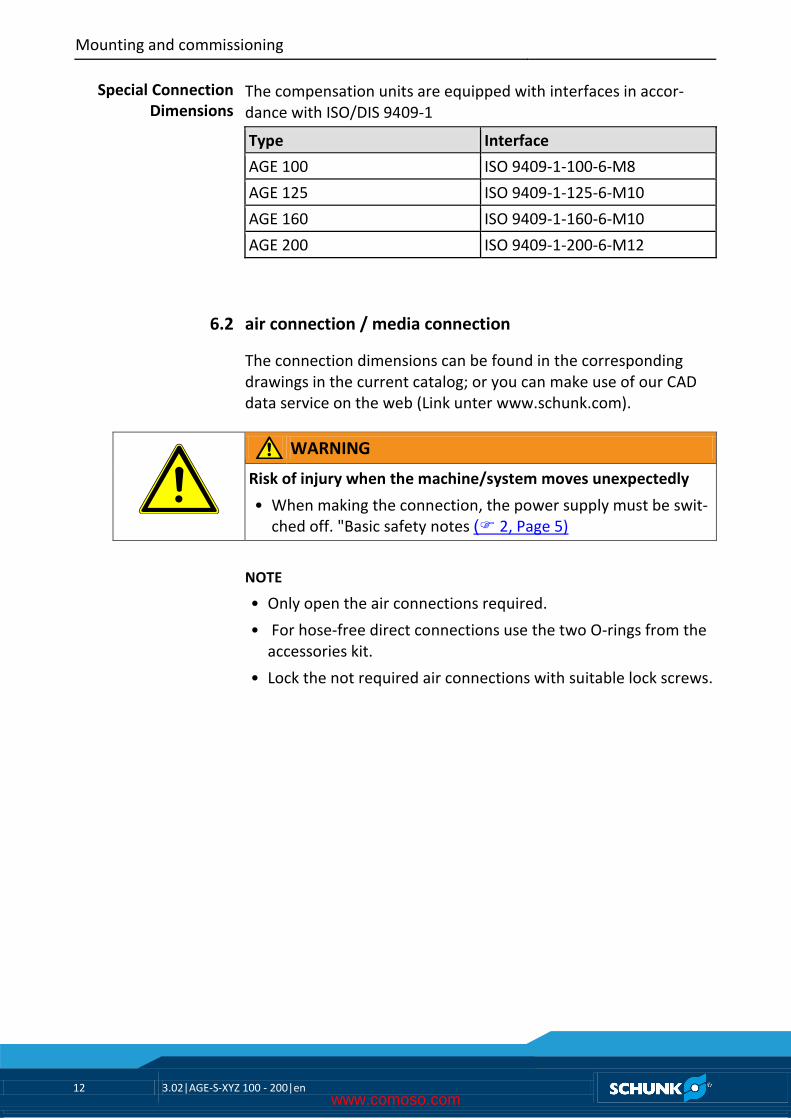
Fig. 2
A unlock AGE
B lock AGE
C activate position memory
D pneumatic booster in Z-direction
www.comoso.com
Mounting and commissioning
14 3.02|AGE-S-XYZ 100 - 200|en
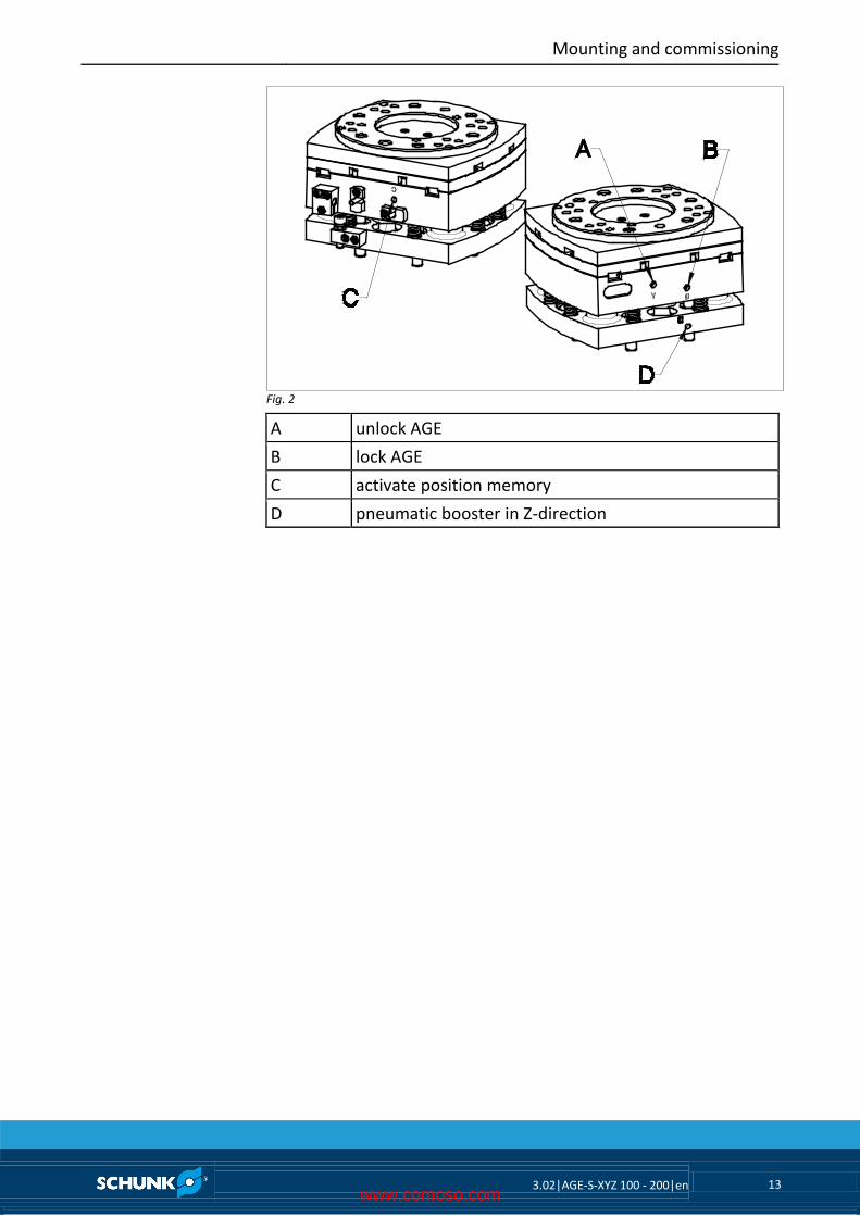
Mounting of the sensors
The magnetic switches are accessories and must be ordered sepa-rately. The units have been prepared by SCHUNK for the use of type MMS-K 65 magnetic switches and INK/INW 80.
Electronic magnetic switch (MMS-K 65) for piston stroke control for XY types
Fig. 3
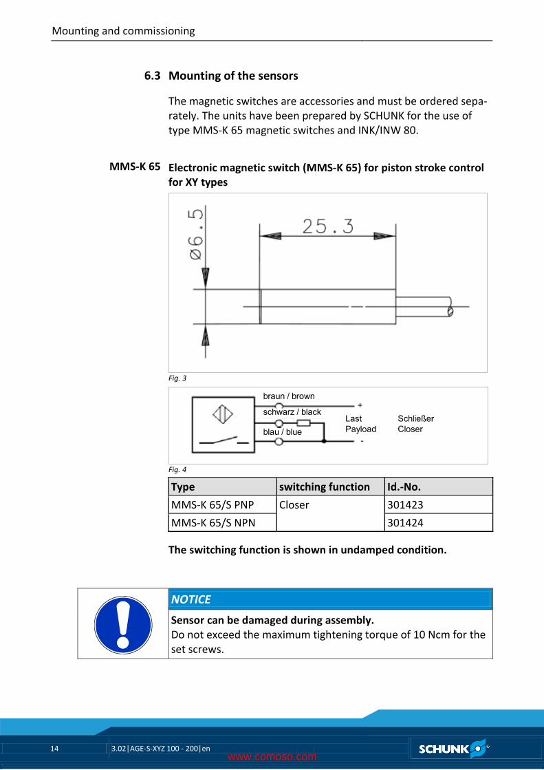
braun / brown
schwarz / black
blau / blueLastPayload
+
-
SchließerCloser
Fig. 4
Type switching function Id.-No.
MMS-K 65/S PNP Closer 301423
MMS-K 65/S NPN 301424
The switching function is shown in undamped condition.
NOTICE
Sensor can be damaged during assembly. Do not exceed the maximum tightening torque of 10 Ncm for the set screws.
6.3
MMS-K 65
www.comoso.com
Mounting and commissioning
3.02|AGE-S-XYZ 100 - 200|en 15
NOTE Ferromagnetic material changes the switching positions of the sensor. For example: Adapter plate made of ordinary steel. At ferromagnetic adapter plates:
• The module must firstly be mounted on the adapter plate
• Then, the positions of the magnetic switch have to be set
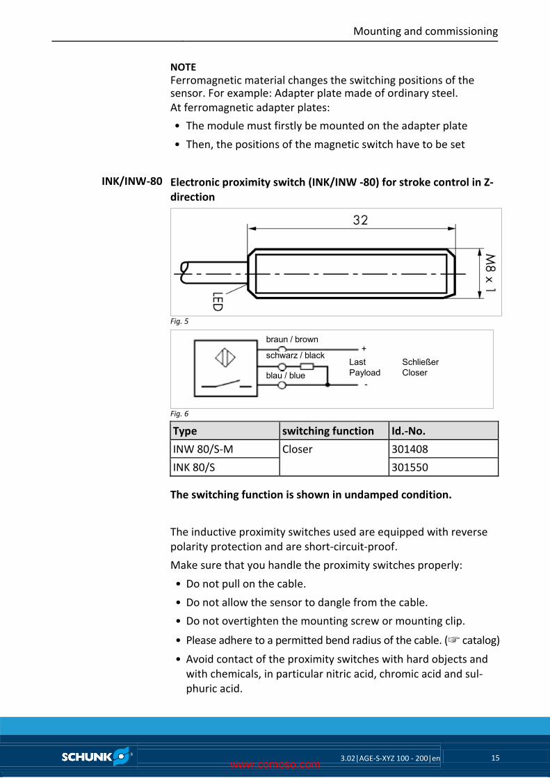
Electronic proximity switch (INK/INW -80) for stroke control in Z-direction
Fig. 5
braun / brown
schwarz / black
blau / blueLastPayload
+
-
SchließerCloser
Fig. 6
Type switching function Id.-No.
INW 80/S-M Closer 301408
INK 80/S 301550
The switching function is shown in undamped condition.
The inductive proximity switches used are equipped with reverse polarity protection and are short-circuit-proof.
Make sure that you handle the proximity switches properly:
• Do not pull on the cable.
• Do not allow the sensor to dangle from the cable.
• Do not overtighten the mounting screw or mounting clip.
• Please adhere to a permitted bend radius of the cable. (☞ catalog)
• Avoid contact of the proximity switches with hard objects and with chemicals, in particular nitric acid, chromic acid and sul-phuric acid.
INK/INW-80
www.comoso.com
Mounting and commissioning
16 3.02|AGE-S-XYZ 100 - 200|en
The inductive proximity switches are electronic components, which can react sensitively to high-frequency interference or elec-tromagnetic fields.
• Check to make sure that the cable is fastened and installed cor-rectly. Provide for sufficient clearance to sources of high-frequency interference and their supply cables.
• Parallel switching of several sensor outputs of the same type (npn, pnp) is permissible, but does not increase the permissible load current.
• Note that the leakage current of the individual sensors (ca. 2 mA) is cumulative.
Fig. 7
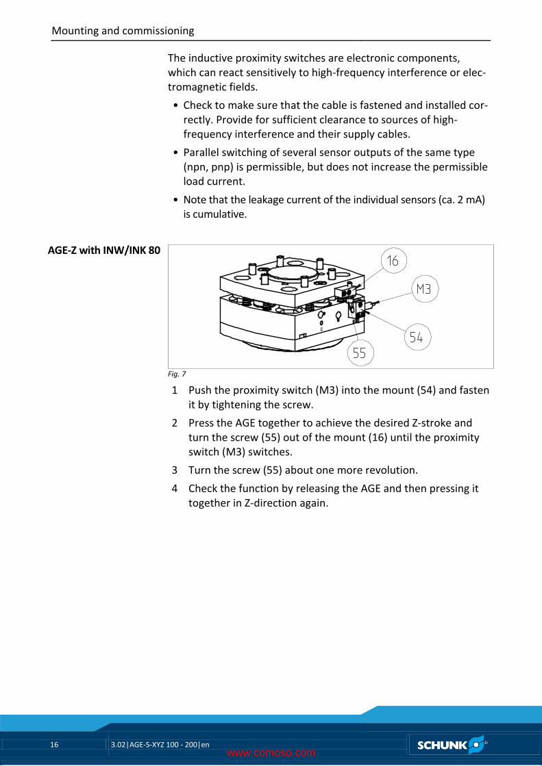
1 Push the proximity switch (M3) into the mount (54) and fasten it by tightening the screw.
2 Press the AGE together to achieve the desired Z-stroke and turn the screw (55) out of the mount (16) until the proximity switch (M3) switches.
3 Turn the screw (55) about one more revolution.
4 Check the function by releasing the AGE and then pressing it together in Z-direction again.
AGE-Z with INW/INK 80
www.comoso.com
Mounting and commissioning
3.02|AGE-S-XYZ 100 - 200|en 17
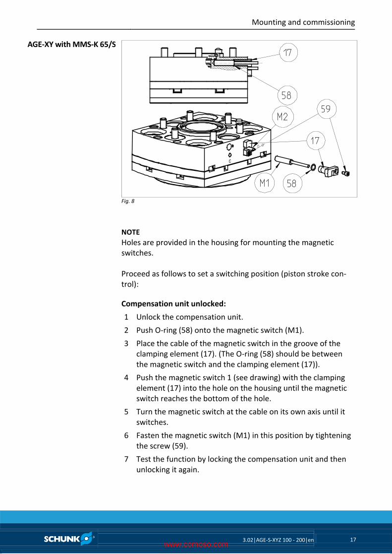
Fig. 8
NOTE Holes are provided in the housing for mounting the magnetic switches. Proceed as follows to set a switching position (piston stroke con-trol):
Compensation unit unlocked:
1 Unlock the compensation unit.
2 Push O-ring (58) onto the magnetic switch (M1).
3 Place the cable of the magnetic switch in the groove of the clamping element (17). (The O-ring (58) should be between the magnetic switch and the clamping element (17)).
4 Push the magnetic switch 1 (see drawing) with the clamping element (17) into the hole on the housing until the magnetic switch reaches the bottom of the hole.
5 Turn the magnetic switch at the cable on its own axis until it switches.
6 Fasten the magnetic switch (M1) in this position by tightening the screw (59).
7 Test the function by locking the compensation unit and then unlocking it again.
AGE-XY with MMS-K 65/S
www.comoso.com
Mounting and commissioning
18 3.02|AGE-S-XYZ 100 - 200|en
Compensation unit locked:
1 Lock the compensation unit.
2 Push O-ring (58) onto the magnetic switch (M2).
3 Place the cable of the magnetic switch in the groove of the clamping element (17).
(The O-ring (58) should be between the magnetic switch and the clamping element (17)).
4 Push the magnetic switch 2 (see drawing) with the clamping element (17) into the hole on the housing until the magnetic switch reaches the bottom of the hole.
5 Turn the magnetic switch at the cable on its own axis until it switches.
6 Fasten the magnetic switch (M2) in this position by tightening the screw (59).
7 Test the function by unlocking the compensation unit and then locking it again.
www.comoso.com
Maintenance and care
3.02|AGE-S-XYZ 100 - 200|en 19
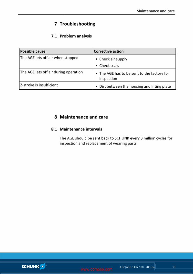
Troubleshooting
Problem analysis
Possible cause Corrective action
The AGE lets off air when stopped • Check air supply
• Check seals
The AGE lets off air during operation • The AGE has to be sent to the factory for inspection
Z-stroke is insufficient • Dirt between the housing and lifting plate
Maintenance and care
Maintenance intervals
The AGE should be sent back to SCHUNK every 3 million cycles for inspection and replacement of wearing parts.
7
7.1
8
8.1
www.comoso.com
Assembly drawing
20 3.02|AGE-S-XYZ 100 - 200|en
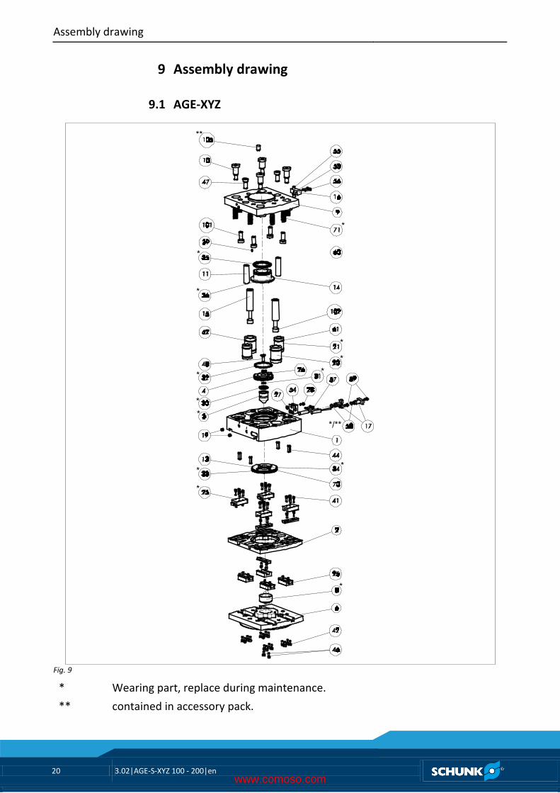
Assembly drawing
AGE-XYZ
**
*
*
*
**
*
*
*
*
*/**
**
*
*
Fig. 9
* Wearing part, replace during maintenance.
** contained in accessory pack.
9
9.1
www.comoso.com
Assembly drawing
3.02|AGE-S-XYZ 100 - 200|en 21
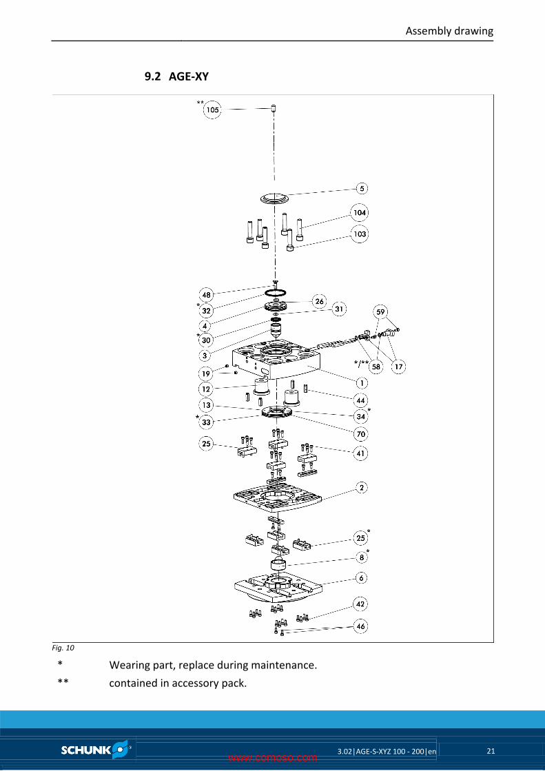
AGE-XY
Fig. 10
* Wearing part, replace during maintenance.
** contained in accessory pack.
9.2
www.comoso.com
Assembly drawing
22 3.02|AGE-S-XYZ 100 - 200|en
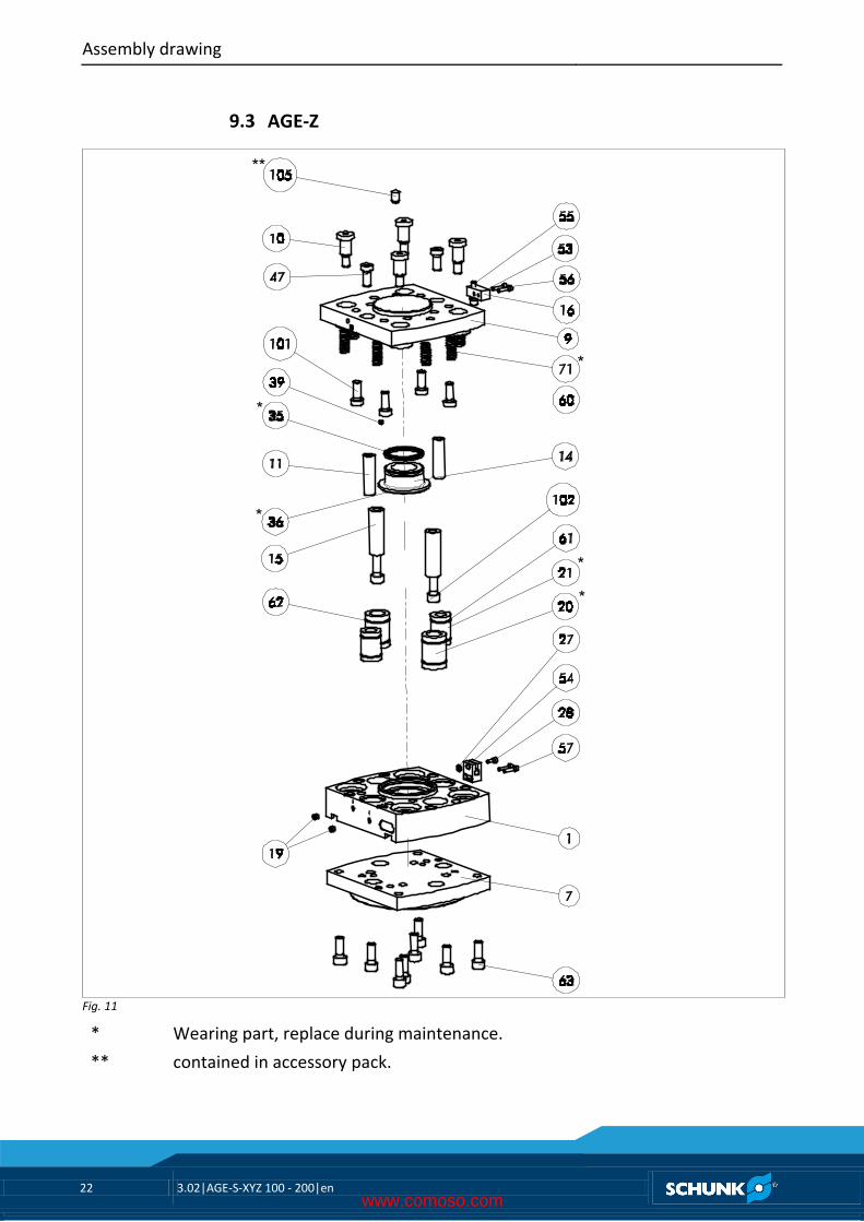
AGE-Z
**
*
*
*
*
*
Fig. 11
* Wearing part, replace during maintenance.
** contained in accessory pack.
9.3
www.comoso.com
Accessories kit
3.02|AGE-S-XYZ 100 - 200|en 23
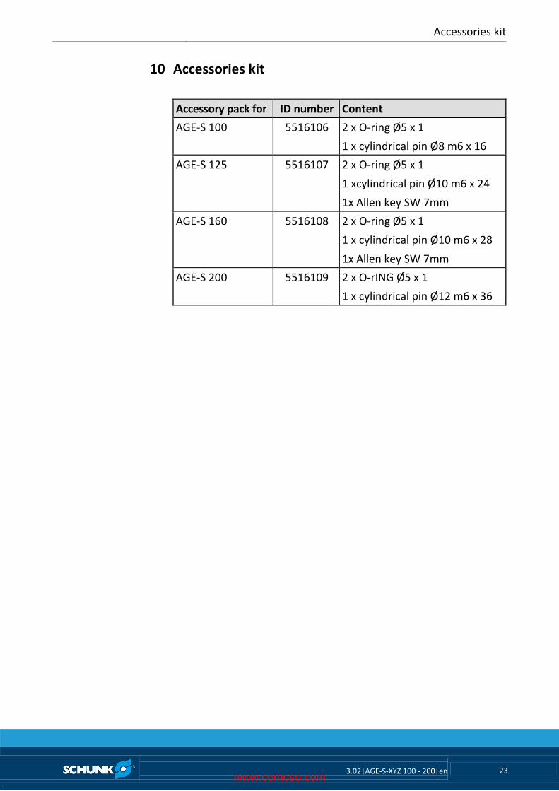
Accessories kit
Accessory pack for ID number Content
AGE-S 100 5516106 2 x O-ring Ø5 x 1
1 x cylindrical pin Ø8 m6 x 16
AGE-S 125 5516107 2 x O-ring Ø5 x 1
1 xcylindrical pin Ø10 m6 x 24
1x Allen key SW 7mm
AGE-S 160 5516108 2 x O-ring Ø5 x 1
1 x cylindrical pin Ø10 m6 x 28
1x Allen key SW 7mm
AGE-S 200 5516109 2 x O-rING Ø5 x 1
1 x cylindrical pin Ø12 m6 x 36
10
www.comoso.com
Translation of original declaration of incorporation
24 3.02|AGE-S-XYZ 100 - 200|en
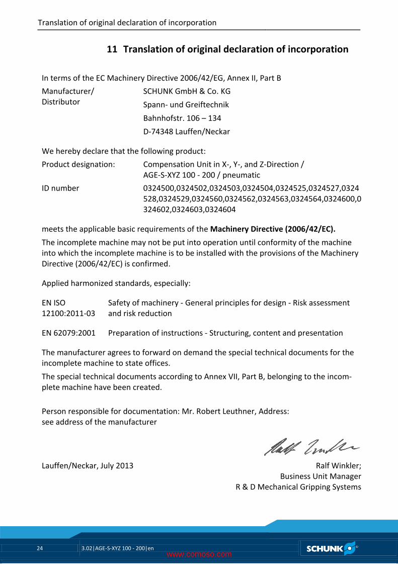
Translation of original declaration of incorporation
In terms of the EC Machinery Directive 2006/42/EG, Annex II, Part B
Manufacturer/ Distributor
SCHUNK GmbH & Co. KG
Spann- und Greiftechnik
Bahnhofstr. 106 – 134
D-74348 Lauffen/Neckar
We hereby declare that the following product:
Product designation: Compensation Unit in X-, Y-, and Z-Direction / AGE-S-XYZ 100 - 200 / pneumatic
ID number 0324500,0324502,0324503,0324504,0324525,0324527,0324528,0324529,0324560,0324562,0324563,0324564,0324600,0324602,0324603,0324604
meets the applicable basic requirements of the Machinery Directive (2006/42/EC).
The incomplete machine may not be put into operation until conformity of the machine into which the incomplete machine is to be installed with the provisions of the Machinery Directive (2006/42/EC) is confirmed.
Applied harmonized standards, especially:
EN ISO 12100:2011-03
Safety of machinery - General principles for design - Risk assessment and risk reduction
EN 62079:2001 Preparation of instructions - Structuring, content and presentation
The manufacturer agrees to forward on demand the special technical documents for the incomplete machine to state offices.
The special technical documents according to Annex VII, Part B, belonging to the incom-plete machine have been created.
Person responsible for documentation: Mr. Robert Leuthner, Address: see address of the manufacturer
Lauffen/Neckar, July 2013 Ralf Winkler;
Business Unit Manager R & D Mechanical Gripping Systems
11
www.comoso.com