Embed Size (px)
Citation preview
Installation instructions SmartController
CR2530
7390
975
/ 00
09 /
2013
UK

SmartController CR2530
2
Contents1 Preliminary note � � � � � � � � � � � � � � � � � � � � � � � � � � � � � � � � � � � � � � � � � � � � � � � � � 4
1�1 Symbols used� � � � � � � � � � � � � � � � � � � � � � � � � � � � � � � � � � � � � � � � � � � � � � � 41�2 Warning signs used � � � � � � � � � � � � � � � � � � � � � � � � � � � � � � � � � � � � � � � � � � 4
2 Safety instructions � � � � � � � � � � � � � � � � � � � � � � � � � � � � � � � � � � � � � � � � � � � � � � � 52�1 General� � � � � � � � � � � � � � � � � � � � � � � � � � � � � � � � � � � � � � � � � � � � � � � � � � � � 52�2 Target group � � � � � � � � � � � � � � � � � � � � � � � � � � � � � � � � � � � � � � � � � � � � � � � � 52�3 Electrical connection � � � � � � � � � � � � � � � � � � � � � � � � � � � � � � � � � � � � � � � � � 52�4 Housing temperature � � � � � � � � � � � � � � � � � � � � � � � � � � � � � � � � � � � � � � � � � 52�5 Tampering with the device � � � � � � � � � � � � � � � � � � � � � � � � � � � � � � � � � � � � � 62�6 Electromagnetic compatibility� � � � � � � � � � � � � � � � � � � � � � � � � � � � � � � � � � � 62�7 Electrical welding on vehicles and plants � � � � � � � � � � � � � � � � � � � � � � � � � � 6
3 Functions and features � � � � � � � � � � � � � � � � � � � � � � � � � � � � � � � � � � � � � � � � � � � � 64 Installation� � � � � � � � � � � � � � � � � � � � � � � � � � � � � � � � � � � � � � � � � � � � � � � � � � � � � � 7
4�1 Fixing � � � � � � � � � � � � � � � � � � � � � � � � � � � � � � � � � � � � � � � � � � � � � � � � � � � � � 74�2 Installation position� � � � � � � � � � � � � � � � � � � � � � � � � � � � � � � � � � � � � � � � � � � 74�3 Mounting surface � � � � � � � � � � � � � � � � � � � � � � � � � � � � � � � � � � � � � � � � � � � � 84�4 Heat dissipation � � � � � � � � � � � � � � � � � � � � � � � � � � � � � � � � � � � � � � � � � � � � � 8
5 Electrical connection� � � � � � � � � � � � � � � � � � � � � � � � � � � � � � � � � � � � � � � � � � � � � � 95�1 Wiring � � � � � � � � � � � � � � � � � � � � � � � � � � � � � � � � � � � � � � � � � � � � � � � � � � � � � 95�2 Ground connection � � � � � � � � � � � � � � � � � � � � � � � � � � � � � � � � � � � � � � � � � � � 95�3 Fuses � � � � � � � � � � � � � � � � � � � � � � � � � � � � � � � � � � � � � � � � � � � � � � � � � � � � � 95�4 Laying the supply and signal cables� � � � � � � � � � � � � � � � � � � � � � � � � � � � � 105�5 Frequency and analogue inputs � � � � � � � � � � � � � � � � � � � � � � � � � � � � � � � � 105�6 Resistor inputs � � � � � � � � � � � � � � � � � � � � � � � � � � � � � � � � � � � � � � � � � � � � � �115�7 Connection technology� � � � � � � � � � � � � � � � � � � � � � � � � � � � � � � � � � � � � � � �11
6 Set-up � � � � � � � � � � � � � � � � � � � � � � � � � � � � � � � � � � � � � � � � � � � � � � � � � � � � � � � � 126�1 Programming � � � � � � � � � � � � � � � � � � � � � � � � � � � � � � � � � � � � � � � � � � � � � � 126�2 Required documentation � � � � � � � � � � � � � � � � � � � � � � � � � � � � � � � � � � � � � 12
7 Technical data� � � � � � � � � � � � � � � � � � � � � � � � � � � � � � � � � � � � � � � � � � � � � � � � � � 137�1 Mechanical and electric data � � � � � � � � � � � � � � � � � � � � � � � � � � � � � � � � � � 137�2 Test standards and regulations � � � � � � � � � � � � � � � � � � � � � � � � � � � � � � � � 157�3 Input characteristics � � � � � � � � � � � � � � � � � � � � � � � � � � � � � � � � � � � � � � � � � 167�4 Output characteristics� � � � � � � � � � � � � � � � � � � � � � � � � � � � � � � � � � � � � � � � 187�5 Wiring � � � � � � � � � � � � � � � � � � � � � � � � � � � � � � � � � � � � � � � � � � � � � � � � � � � � 20
8 Maintenance, repair and disposal� � � � � � � � � � � � � � � � � � � � � � � � � � � � � � � � � � � 219 Approvals / standards � � � � � � � � � � � � � � � � � � � � � � � � � � � � � � � � � � � � � � � � � � � � 21

UK
SmartController CR2530
3
This document is the original instructions�
Licences and trademarksAll trademarks and company names are subject to the copyright of the respective companies�
SmartController CR2530
4
1 Preliminary noteThis document applies to devices of the type "SmartController" (art� no�: CR2530)� These instructions are part of the device�This document is intended for specialists� These specialists are people who are qualified by their appropriate training and their experience to see risks and to avoid possible hazards that may be caused during operation or maintenance of the device� The document contains information about the correct handling of the device�Read this document before use to familiarise yourself with operating conditions, installation and operation� Keep this document during the entire duration of use of the device�Adhere to the safety instructions�
1.1 Symbols used► Instructions> Reaction, result[…] Designation of keys, buttons or indications→ Cross-reference
Important note Non-compliance can result in malfunction or interference�Information Supplementary note
1.2 Warning signs used
WARNINGWarning of serious personal injury� Death or serious irreversible injuries may result�
CAUTION Warning of personal injury� Slight reversible injuries may result�
NOTE Warning of damage to property�

UK
SmartController CR2530
5
2 Safety instructions2.1 GeneralThese instructions are part of the device� They contain texts and figures concerning the correct handling of the device and must be read before installation or use� Observe the operating instructions� Non-observance of the instructions, operation which is not in accordance with use as prescribed below, wrong installation or incorrect handling can seriously affect the safety of operators and machinery�
2.2 Target groupThese instructions are intended for authorised persons according to the EMC and low-voltage directives� The device must only be installed, connected and put into operation by a qualified electrician�
2.3 Electrical connectionDisconnect the unit externally before handling it� If necessary, also disconnect any independently supplied output load circuits�If the device is not supplied by the mobile on-board system (12/24 V battery operation), it must be ensured that the external voltage is generated and supplied according to the criteria for safety extra-low voltage (SELV) as this voltage is supplied without further measures to the connected controller, the sensors and the actuators�The wiring of all signals in connection with the SELV circuit of the device must also comply with the SELV criteria (safety extra-low voltage, safe electrical isolation from other electric circuits)�If the supplied SELV voltage is externally grounded (SELV becomes PELV), the responsibility lies with the user and the respective national installation regulations must be complied with� All statements in this document refer to the device the SELV voltage of which is not grounded�The connection terminals may only be supplied with the signals indicated in the technical data and/or on the device label and only the approved accessories of ifm electronic may be connected�
2.4 Housing temperatureAs described in the technical specifications below the device can be operated in a wide ambient temperature range� Because of the additional internal heating the housing walls can have high perceptible temperatures when touched in hot environments�

SmartController CR2530
6
2.5 Tampering with the deviceIn case of malfunctions or uncertainties please contact the manufacturer� Tampering with the device can seriously affect the safety of operators and machinery� This is not permitted and leads to the exclusion of any liability and warranty claims�
2.6 Electromagnetic compatibilityThis is a class A product� It can cause radio interference in domestic areas� In this case the operator is requested to take appropriate measures�
2.7 Electrical welding on vehicles and plantsWelding work on the chassis frame must only be carried out by qualified persons�Remove and cover the plus and minus terminals of the batteries� Disconnect all contacts of the controller from the on-board system prior to welding on the vehicle or plant� Connect the earth terminal of the welding device directly to the part to be welded�Do not touch the controller or electric cables with the welding electrode or the earth terminal of the welding device�Protect the controller against weld slag�
3 Functions and featuresThe freely programmable controllers of the "SmartController" series are rated for use under difficult conditions (e�g� extended temperature range, strong vibration, intensive EMC interference)�They are suited for direct installation in machines in mobile and robust applications� Integrated hardware and software functions (operating system) offer high protection for the machine�The controllers can be used as CANopen master�
WARNINGThe SmartController series is not approved for safety tasks in the field of safety of persons�
WARNINGThe user is responsible for the safe function of the application programs which he created himself� If necessary, he must additionally carry out an approval test by corresponding supervisory and test organisations according to the national regulations�
UK
SmartController CR2530
7
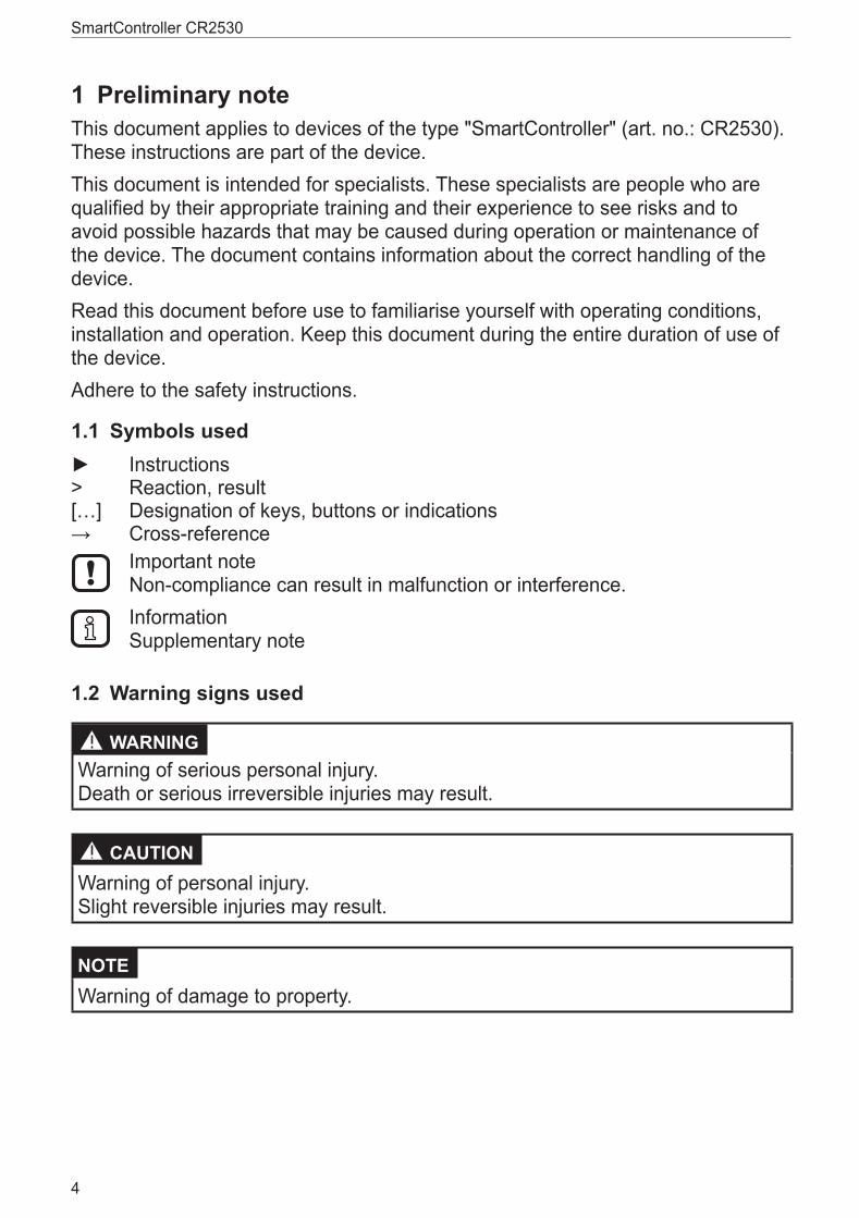
4 Installation4.1 Fixing
► Fix the controller to a flat surface using 4 M5 screws� Screw material: steel or stainless steel Tightening torque: 8 ±2 Nm
NOTE Use screws with a low head to avoid that the connector is damaged when placed and locked�
Screws to be used (examples) Standard
Button head hexagon socket screws (M5 x L) ISO 7380
Cylinder screws with hexagon socket and low head (M5 x L) DIN 7984
Cutting screws for metric ISO thread with low head DIN 7500
Example button head hexagon socket screw
4.2 Installation position ► Align the controller so that the cable entries of the connectors face downwards�
Preferred installation position

SmartController CR2530
8
4.3 Mounting surface
NOTE The housing must not be exposed to any torsional forces or mechanical stress�
► Use compensating elements if there is no flat mounting surface available�
Mounting surface
4.4 Heat dissipation ► Ensure sufficient heat dissipation as the internal heating of the electronics is conducted away via the housing�
► In case of sandwich mounting of controllers use spacers�
Heat dissipation and sandwich mounting

UK
SmartController CR2530
9
5 Electrical connection5.1 WiringWiring (→ 7 Technical data)
Only connect the connector pins as shown in the pin layout� Unspecified connector pins remain unconnected�
► Connect all indicated supply cables and GND terminals�
5.2 Ground connection ► To ensure the protection of the device against electrical interference, the housing must be connected to GND (e�g� to the ground of the vehicle)�
1: Drill holes for ground connection
► Establish a connection between the device and the ground of the vehicle using M5 screws� Screws to be used (→ 4.1 Fixing)
5.3 Fuses ► The individual electric circuits must be protected in order to protect the whole system�
Potential Description Pin no. Fuse
VBB S Supply voltage sensors/module 10 ≤ 2 A T
VBB 1 Supply voltage output group 1 19 ≤ 15 A
VBB 2 Supply voltage output group 2 01 ≤ 15 A
SmartController CR2530
10
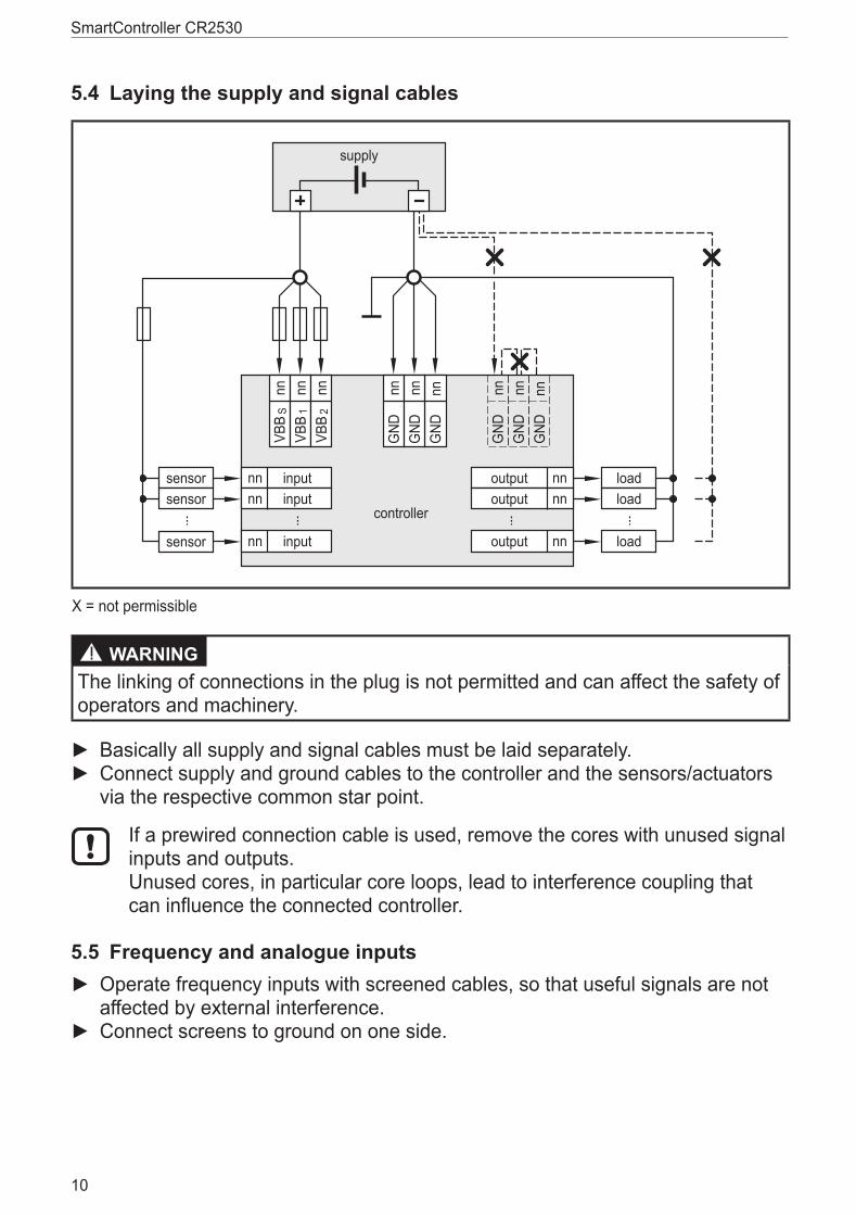
5.4 Laying the supply and signal cables
supply
output nn
output nn
output nncontroller
VBB
Snn
VBB
1nn
VBB
2nn
GND
nnG
NDnn
GND
nn
inputnn
inputnn
inputnnsensor
sensor
sensorload
load
loadG
NDnn
GND
nnG
NDnn
X = not permissible
WARNINGThe linking of connections in the plug is not permitted and can affect the safety of operators and machinery�
► Basically all supply and signal cables must be laid separately� ► Connect supply and ground cables to the controller and the sensors/actuators via the respective common star point�
If a prewired connection cable is used, remove the cores with unused signal inputs and outputs� Unused cores, in particular core loops, lead to interference coupling that can influence the connected controller�
5.5 Frequency and analogue inputs ► Operate frequency inputs with screened cables, so that useful signals are not affected by external interference�
► Connect screens to ground on one side�

UK
SmartController CR2530
11
5.6 Resistor inputs
supply
controllerVB
B S
nnVB
B 1
nnVB
B 2
nn
GND
nnG
NDnn
GND
nn
inputRresistorinputRresistor
Ground return resistor inputs
► Equip each resistor with an own, separated ground return to ensure measurement accuracy�
5.7 Connection technology
NOTE Only connect the 55-pole connectors when the supply voltage is disconnected� No "hot plugging" is permitted�

SmartController CR2530
12
6 Set-up6.1 ProgrammingThe user can easily create the application software by means of the IEC 61131-3 compliant programming system CoDeSys 2�3�
6.2 Required documentationIn addition to the CoDeSys programming system, the following documents are required for programming and set-up of the device:
● Programming manual CoDeSys V2�3 (alternatively as online help)
● SmartController system manual (alternatively as online help)
The manuals can be downloaded from the internet: www.ifm.com → Data sheet search → CR2530 → More informationCoDeSys and SmartController online help: www.ifm.com → Service → Download → Systems for mobile machines**) Download area with registration

UK
SmartController CR2530
13
7 Technical data7.1 Mechanical and electric dataControl systems
ifm electronic gmbh ● Friedrichstraße 1 ● 45128 Essen We reserve the right to make technical alterations without prior notice! 20.09.2013CR2530 / Page 1
CR2530 1325,5
2680
15
45°
153
LED43
±0,5
±1
106,5 ±1
Mobile controllerSmartController
16 inputs16 outputs
2 CAN interfaces
Programming to IEC 61131-3
8...32 V DC
Technical data Controller as black box system for the implementation of a central or decentralised system design
Mechanical dataHousing closed metal housing with ange fastening
Dimensions (H x W x D) 153 x 132 x 43 mm
Installation screw connection by means of 4 M5 x L screws to DIN 7500 or DIN 7984 mounting position horizontal or vertical to the mounting wall
Connection 1 connector 55-pole, locked, reverse polarity protection, type AMP or Framatome contacts AMP-Junior-Timer, crimp connection 0.5/2.5 mm²
Weight 1.0 kg
Housing/storage temperature – 40...85 °C (depending on the load) / – 40...85 °C
Protection rating IP 67 (for inserted connector with individually sealed cores, e.g. EC2084)
Electrical dataInput/output channels (total) 32 (16 inputs / 16 outputs)
Inputs con gurabledigital for positive/negative sensor signals, positive with diagnostic capabilities
analogue (0...10/32 V, 0...20 mA, ratiometric)frequency (≤ 30 kHz)
resistance measurement (16 Ω...30 kΩ)
Outputs con gurabledigital, positive switching (high side)
analogue (0.02...10 V)PWM output (20...250 Hz), current-controlled
Operating voltage 8...32 V DC
Overvoltage ≤ 36 V for t ≤ 10 s
Undervoltage detection for UB ≤ 7.8 V
Undervoltage shutdown for UB < 7.0 V
Reverse polarity protection yes
Current consumption 50 mA (at 24 V DC)
CAN interfaces 1...2 baud rate communication pro le
CAN interface 2.0 A/B, ISO 1189850 Kbits/s...1 Mbit/s (default 250 Kbits/s)
CANopen, CiA DS 301 V4.01, CiA DS 306 V1.3or SAE J 1939 or free protocol
Processor Freescale PowerPC, 50 MHz

SmartController CR2530
14
ifm electronic gmbh ● Friedrichstraße 1 ● 45128 Essen We reserve the right to make technical alterations without prior notice! 20.09.2013CR2530 / Page 2
CR2530 Technical data
Control systems
Device monitoring undervoltage monitoringwatchdog function
check sum test for program and systemexcess temperature monitoring
Physical memory ash: 1.5 MbytesRAM: 592 Kbytes
remanent memory: 2 Kbytes
Memory allocation see system manualwww.ifm.com → Data sheet search → CR2530 → More information
Software/programmingProgramming system CoDeSys version 2.3 (IEC 61131-3)
IndicatorsStatus LED LED red / LED green
Operating states
No longer valid if the colours and/or ashing modes are changed by the application program.
Colour Status Description– permanently off no operating voltage
red/green 1 x on initialisation or reset checks
green 5 Hz no operating system loaded
2 Hz application is running (RUN)
permanently on application stopped (STOP)
red 5 Hz application stopped due to undervoltagepermanently on system fault (fatal error)

UK
SmartController CR2530
15
7.2 Test standards and regulations
ifm electronic gmbh ● Friedrichstraße 1 ● 45128 Essen We reserve the right to make technical alterations without prior notice! 20.09.2013CR2530 / Page 3
CR2530 Technical data
Control systems
Test standards and regulationsCE marking EN 61000-6-2: 2005 Electromagnetic compatibility (EMC)
noise immunity
EN 61000-6-4: 2007 Electromagnetic compatibility (EMC)radiation of interference
E1 marking UN/ECE-R10 Radiation of interference immunity with 100 V/m
Electrical tests ISO 7637-2: 2004 Pulse 1, severity level: IV; function state CPulse 2a, severity level: IV; function state APulse 2b, severity level: IV; function state CPulse 3a, severity level: IV; function state APulse 3b, severity level: IV; function state APulse 4, severity level: IV; function state APulse 5, severity level: III; function state C(data valid for the 24V system)Pulse 4, severity level: III; function state C(data valid for the 12 V system)
Climatic tests EN 60068-2-30: 2006 Damp heat, cyclicupper temperature 55 °C, number of cycles: 6
EN 60068-2-78: 2002 Damp heat, steady statetest temperature 40 °C / 93 % RH,test duration: 21 days
EN 60068-2-52: 1996 Salt spray testseverity level 3 (motor vehicle)
Mechanical tests ISO 16750-3: 2007 Test VII; Vibration, randommounting location: vehicle body
EN 60068-2-6: 2008 Vibration, sinusoidal10...500 Hz; 0.72 mm/10 g; 10 cycles/axis
ISO 16750-3: 2007 Bumps30 g/6 ms; 24,000 shocks

SmartController CR2530
16
7.3 Input characteristics
ifm electronic gmbh ● Friedrichstraße 1 ● 45128 Essen We reserve the right to make technical alterations without prior notice! 20.09.2013CR2530 / Page 4
CR2530 Input characteristics
Control systems
IN00...03Analogue / digital inputs
Resolution 12 bits
Accuracy ± 1 % FS
Measuring ranges 0...10 V, 0...32 V, 0...20 mA, ratiometric
Current input 0...20 mA (A) Input resistance 390 Ω
Input frequency ≤ 1 kHz (default 35 Hz)
Voltage input 0...10 V (A) Input resistance 65.6 kΩ
Input frequency ≤ 1 kHz (default 35 Hz)
Voltage input 0...32 V (A) Input resistance 50.7 kΩ
Input frequency ≤ 1 kHz (default 35 Hz)
Voltage input ratiometric (A) Input resistance 50.7 kΩ
Input frequency ≤ 1 kHz (default 35 Hz)
Digital input (BL/H) Input resistance 3.2 kΩ
Input frequency ≤ 1 kHz (default 35 Hz)
Switch-on level > 0.7 UB
Switch-off level < 0.3 UB
Diagnosisshort circuit to VBB
> 0.95 UB
Diagnosisshort circuit to GND / wire break
< 1 V
IN04...05 Digital / resistor inputs
Resolution 12 bits
Digital input (BL/) Input resistance 3.2 kΩ
Input frequency ≤ 1 kHz (default 35 Hz)
Switch-on level > 0.7 UB
Switch-off level < 0.3 UB
Diagnosisshort circuit to VBB
> 0.95 UB
Diagnosisshort circuit to GND / wire break
< 1 V
Voltage on the pin when not connected
≤ 0.2 V

UK
SmartController CR2530
17
ifm electronic gmbh ● Friedrichstraße 1 ● 45128 Essen We reserve the right to make technical alterations without prior notice! 20.09.2013CR2530 / Page 5
CR2530 Input characteristics
Control systems
Resistor input (R) Measuring current < 2.0 mA
Input frequency 50 Hz
Measuring range 16 Ω...30 kΩ
Accuracy ± 2 % FS: 16 Ω...3 kΩ± 5 % FS: 3...15 kΩ± 10 % FS: 15...30 kΩ
Diagnosisshort circuit to VBB
> 31 kΩ
IN06...11Digital inputs
Resolution 12 bits
Digital input (BL/) Input resistance 3.2 kΩ
Input frequency ≤ 1 kHz (default 35 Hz)
Switch-on level > 0.7 UB
Switch-off level < 0.3 UB
Diagnosisshort circuit to VBB
> 0.95 UB
Diagnosisshort circuit to GND / wire break
< 1 V
IN12...15Digital / frequency inputs
Resolution 12 bits
Digital input (BL/) Input resistance 3.2 kΩ
Input frequency ≤ 30 kHz
Switch-on level > 0.35...0.48 UB
Switch-off level < 0.29 UB
Diagnosisshort circuit to VBB
none
Diagnosisshort circuit to GND / wire break
none
Frequency input (FROUT) Input resistance 3.2 kΩ
Input frequency ≤ 30 kHz
Switch-on level > 0.35...0.48 UB
Switch-off level < 0.29 UB

SmartController CR2530
18
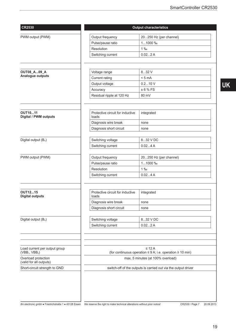
7.4 Output characteristics
ifm electronic gmbh ● Friedrichstraße 1 ● 45128 Essen We reserve the right to make technical alterations without prior notice! 20.09.2013CR2530 / Page 6
CR2530 Output characteristics
Control systems
OUT00...01Digital / PWM outputs
Protective circuit for inductive loads
integrated
Diagnosis wire break via voltage feedback
Diagnosis short circuit via voltage feedback
Diagnosis excessive current integrated
Digital output (BH) Switching voltage 8...32 V DC
Switching current 0.02...2 A
PWM output (PWM) Output frequency 20...250 Hz (per channel)
Pulse/pause ratio 1...1000 ‰
Resolution 1 ‰
Switching current 0.02...2 A
Current-controlled output (PWMI) Output frequency 20...250 Hz (per channel)
Control range 0.02...2 A
Setting resolution 1 mA
Control resolution 2 mA
Load resistance ≥ 6 Ω (at 12 V DC)≥ 12 Ω (at 24 V DC)
Accuracy ± 1.5 % FS
OUT02...07Digital / PWM outputs
Protective circuit for inductive loads
integrated
Diagnosis wire break only if switched offUOUT > 27.5 % VBBS
Diagnosis short circuit only in the logic ON stateUOUT < 93.5 % VBBS
Digital output (BH) Switching voltage 8...32 V DC
Switching current 0.02...2 A
PWM output (PWM) Output frequency 20...250 Hz (per channel)
Pulse/pause ratio 1...1000 ‰
Resolution 1 ‰
Switching current 0.02...2 A
OUT08...09Digital / PWM outputs
Protective circuit for inductive loads
integrated
Diagnosis wire break none
Diagnosis short circuit none
Digital output (BH) Switching voltage 8...32 V DC
Switching current 0.02...2 A
UK
SmartController CR2530
19
ifm electronic gmbh ● Friedrichstraße 1 ● 45128 Essen We reserve the right to make technical alterations without prior notice! 20.09.2013CR2530 / Page 7
CR2530 Output characteristics
Control systems
PWM output (PWM) Output frequency 20...250 Hz (per channel)
Pulse/pause ratio 1...1000 ‰
Resolution 1 ‰
Switching current 0.02...2 A
OUT08_A...09_AAnalogue outputs
Voltage range 8...32 V
Current rating < 5 mA
Output voltage 0.2...10 V
Accuracy ± 6 % FS
Residual ripple at 120 Hz 80 mV
OUT10...11Digital / PWM outputs
Protective circuit for inductive loads
integrated
Diagnosis wire break none
Diagnosis short circuit none
Digital output (BH) Switching voltage 8...32 V DC
Switching current 0.02...4 A
PWM output (PWM) Output frequency 20...250 Hz (per channel)
Pulse/pause ratio 1...1000 ‰
Resolution 1 ‰
Switching current 0.02...4 A
OUT12...15 Digital outputs
Protective circuit for inductive loads
integrated
Diagnosis wire break none
Diagnosis short circuit none
Digital output (BH) Switching voltage 8...32 V DC
Switching current 0.02...2 A
Load current per output group(VBB1, VBB2)
≤ 12 A(for continuous operation ≤ 9 A; i.e. operation ≥ 10 min)
Overload protection(valid for all outputs)
max. 5 minutes (at 100% overload)
Short-circuit strength to GND switch-off of the outputs is carried out via the output driver
SmartController CR2530
20
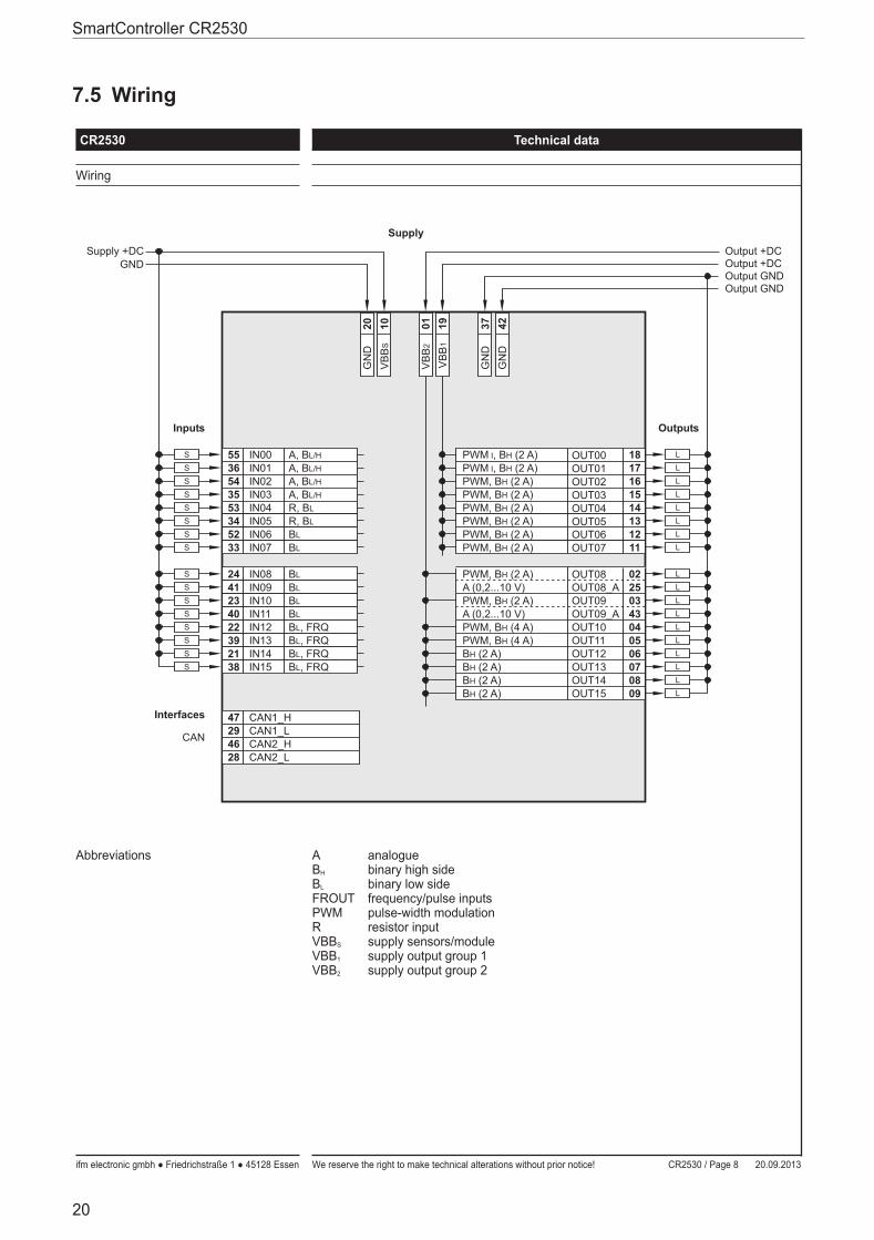
7.5 Wiring
ifm electronic gmbh ● Friedrichstraße 1 ● 45128 Essen We reserve the right to make technical alterations without prior notice! 20.09.2013CR2530 / Page 8
CR2530 Technical data
Control systems
Wiring
55 A, BL/H 18OUT00PWM I, BH (2 A)
20G
ND
01V
BB
2
S
Inputs
36S
54 A, BL/HS
35 A, BL/HS
53 R, BLS
34 R, BLS
52 BLS
33 BLS
24 BLS
41 BLS
23 BLS
40 BLS
22 BL, FRQS
39 BL, FRQS
21 BL, FRQS
38
IN00IN01IN02IN03IN04IN05IN06IN07
IN08IN09IN10IN11IN12IN13IN14IN15 BL, FRQS
L
17OUT01PWM I, BH (2 A) L
16OUT02PWM, BH (2 A) L
15OUT03PWM, BH (2 A) L
14OUT04PWM, BH (2 A) LL
12OUT06PWM, BH (2 A) L
11OUT07PWM, BH (2 A) L
02OUT08PWM, BH (2 A) LL
L
25OUT08_AA (0,2...10 V)03OUT09PWM, BH (2 A) L
43OUT09_AA (0,2...10 V)04OUT10PWM, BH (4 A) L
05OUT11PWM, BH (4 A) L
06OUT12BH (2 A) L
07OUT13BH (2 A)08OUT14BH (2 A) L
09OUT15BH (2 A) L
Outputs
Supply +DCGND
Output +DC
Output GNDOutput GND
37G
ND
Output +DC
A, BL/H
10V
BB
S
Supply
42G
ND
19V
BB
1
13OUT05PWM, BH (2 A)
L
CAN
Interfaces 47 CAN1_H29 CAN1_L46 CAN2_H28 CAN2_L
Abbreviations ABH
BL
FROUTPWMRVBBS
VBB1
VBB2
analoguebinary high sidebinary low sidefrequency/pulse inputspulse-width modulationresistor inputsupply sensors/modulesupply output group 1supply output group 2

UK
SmartController CR2530
21
8 Maintenance, repair and disposalThe unit is maintenance-free�
► Do not open the housing as the device does not contain any components which can be repaired by the user� The device must only be repaired by the manufacturer�
► Dispose of the device in accordance with the national environmental regulations�
9 Approvals / standardsTest standards and regulations (→ 7 Technical data)The EC Declaration of Conformity and approvals can be found at: www.ifm.com → Data sheet search → CR2530 → Approvals