Embed Size (px)
Citation preview
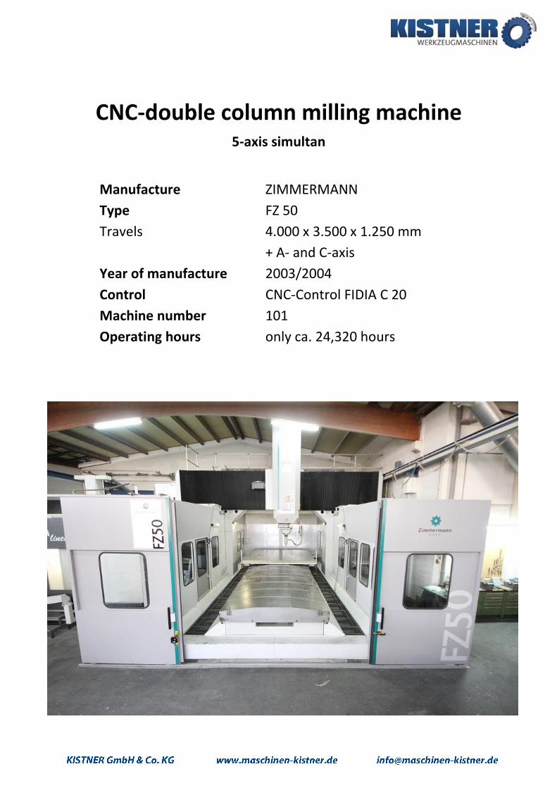
CNC-double column milling machine 5-axis simultan
Manufacture ZIMMERMANN
Type FZ 50
Travels 4.000 x 3.500 x 1.250 mm
+ A- and C-axis
Year of manufacture 2003/2004
Control CNC-Control FIDIA C 20
Machine number 101
Operating hours only ca. 24,320 hours
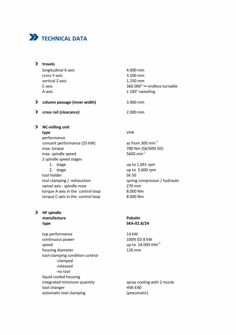
TECHNICAL DATA
travels
longitudinal X-axis 4.000 mm cross Y-axis 3.500 mm vertical Z-axis 1.250 mm
C-axis 360.000° ∞ endless turnable A-axis ± 100° swiveling
column passage (inner width) 3.900 mm
cross rail (clearance) 2.000 mm
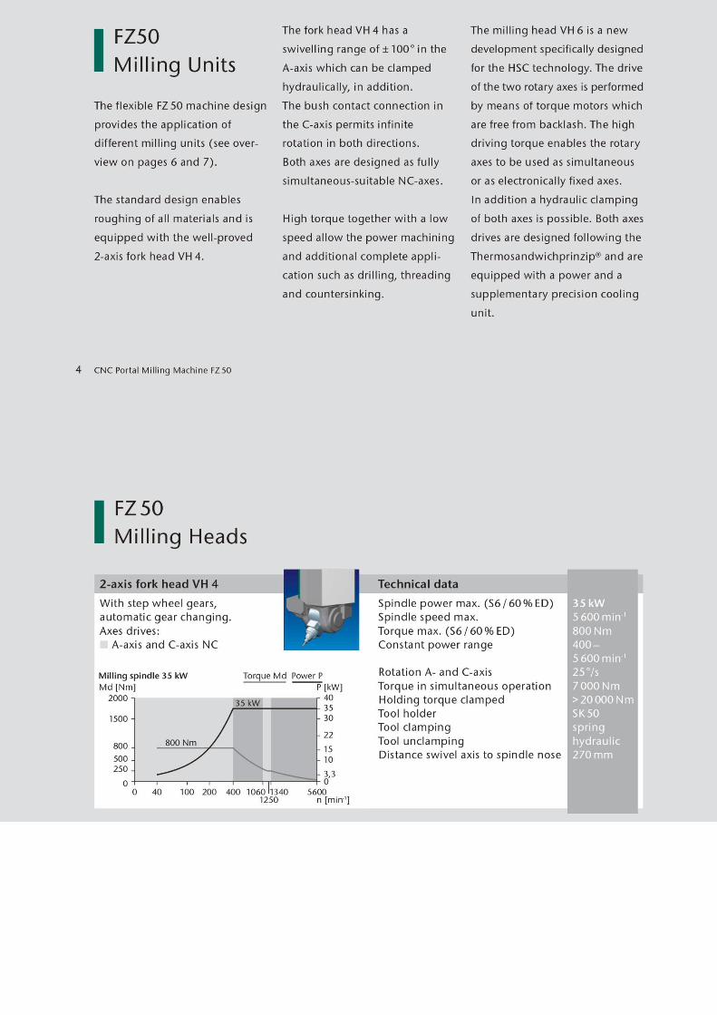
NC-milling unit type VH4
performance consant performance (25 kW) as from 300 min-1
max. torque 780 Nm (S6/60% ED) max. spindle speed 5600 min-1
2 spindle speed stages 1. stage up to 1.091 rpm 2. stage up to 5.600 rpm
tool holder SK 50 tool clamping / -exhaustion spring compressor / hydraulic swivel axis - spindle nose 270 mm torque A-axis in the control loop 8.000 Nm torque C-axis in the control loop 8.000 Nm
HF spindle manufacture Pokolm type SKA-02.8/24 top performance 14 kW continuous power 100% ED 8 kW speed up to 24.000 min-1
housing diameter 126 mm tool-clamping condition control
-clamped -released -no tool liquid cooled housing integrated minimum quantity spray cooling with 2 nozzle tool changer HSK-E40 automatic tool clamping (pneumatic)
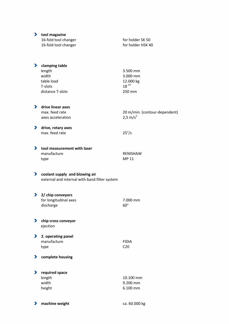
tool magazine
16-fold tool changer for holder SK 50 16-fold tool changer for holder HSK 40
clamping table length 3.500 mm width 3.000 mm table load 12.000 kg T-slots 18 H7 distance T-slots 250 mm
drive linear axes max. feed rate 20 m/min. (contour-dependent) axes acceleration 2,5 m/s2
drive, rotary axes
max. feed rate 25°/s
tool measurement with laser manufacture RENISHAW type MP 11
coolant supply and blowing air external and internal with band filter system
2/ chip conveyors for longitudinal axes 7.000 mm discharge 60°
chip cross conveyor ejection
2. operating panel
manufacture FIDIA type C20
complete housing
required space length 10.100 mm width 9.200 mm height 6.100 mm
machine weight ca. 60.000 kg
DESCRIPTION OF THE MACHINE
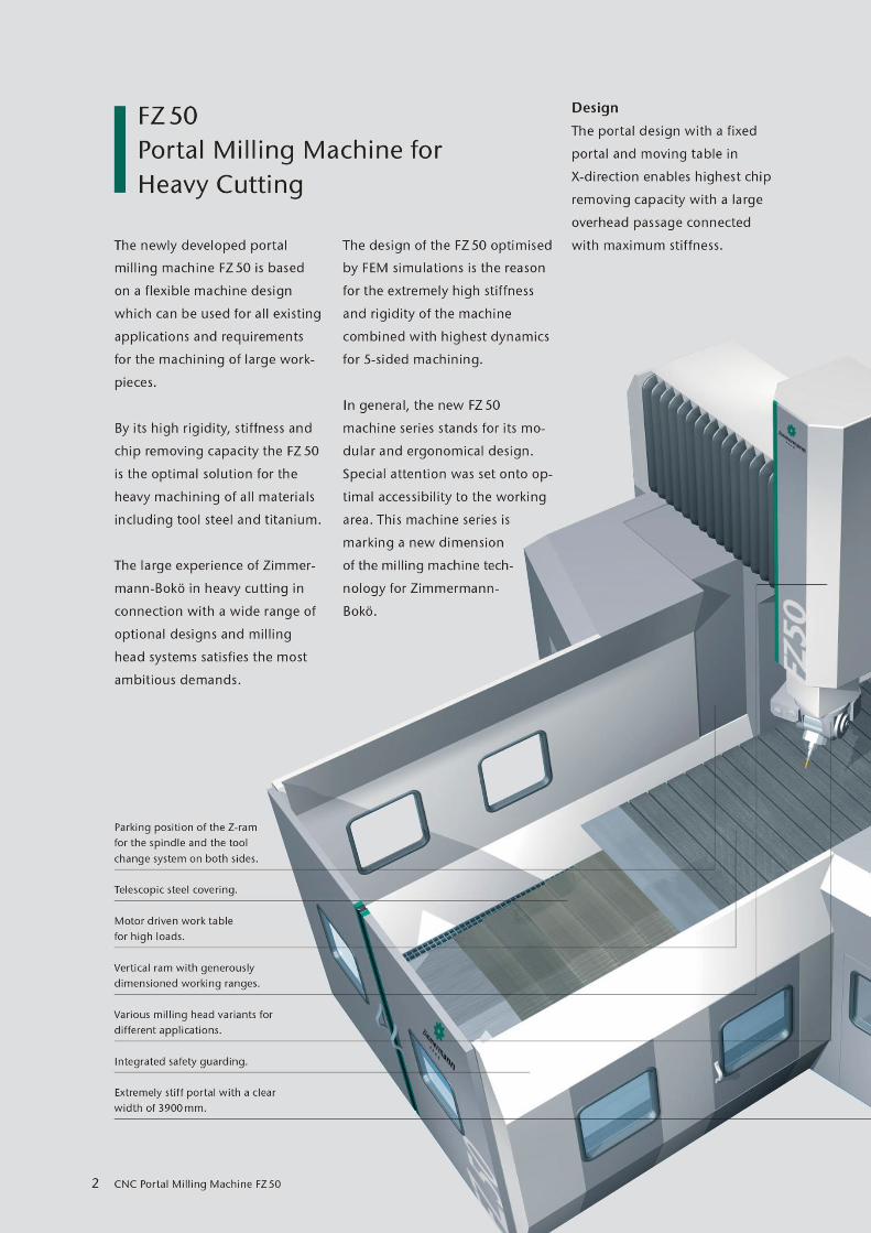
The ZIMMERMANN CNC-double column milling machine FZ 50 is a modular constructed machine
concept in which different working areas, milling spindle and manufacturer or type of the control
can be combined with each other.
Due to the construction with fixed portal and a driving machine table in the direction of X it is
possible to realize an extreme inflexible machine structure for the heavy chip removal of all materials
up to tool-steel and titan.
The moving masses consist of the compound- and Z-slide, as well as machine table driving in the
direction of X.
Because of the generous dimensions of the working area and the high table load, the portal milling
machine FZ 50 provides a wide range of application.
In conjunction with the optional rotary table there are all in all 6 simultaneous NC axes which are
available to the user.
Complexes components can be complete and economical processed in just one clamping.
The construction of the FZ 50 which is optimized with FEM simulation enables next to extreme
machine rigidity and stability however highest dynamic at the 5-sided machining.
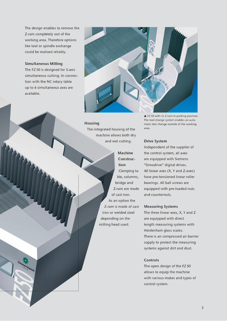
The portal milling machine FZ 50 with the housing which is integrated in the machine concept is
designed so, that options like tool changer, chip conveyor, coolant unit, extraction unit etc. can be
adapted without any problems.
The structure of the machine is constructed for die wet and dry machining.
The machine corresponds to the CE-norm.
machine frame and guidance
The clamping table, the gantry column, the cross rail of the portal as well as the compound
slide and the Z-sliders are made of grey cast iron.
All guidances, the drive as well as the measuring system are protected by bellows or steel
telescopic covers. The inclined arrangement minimizes the deposition of the chips.
axle drive
All axes are equipped with digital Siemens-drives „Simodrive“ independent of the
manufacturer of the control. The power transmission is realised typical by ball screw drive.
The Z-axis have a hydraulic weight counterbalance, which compensate ca. 75 % of the
moving masses.
linear guidance prestressed roller guides
ball screw drive ball srew spindle with prestressed double nut
in all axes
measuring system
The 3 linear axes X, Y and Z have a directly length measuring system with HEIDENHAIN-glass
measuring (at axis length over 3 m steel scale). The measuring systems are sealing air applied
as a safeguard against pollution (compressed air are made on site).
resolution of the measuring system: 0,001 mm
accuracy class of the measuring system: ± 0,005 mm
Attention:
The compressed air, which is delivered from network on site (6 bar )must be at least
correspond to the class 4 according to DIN ISO 8573-1. This applies to both the sealing air of
the spindle and the measuring system.
This means:
solid: max. particle size = 15 µm
max. particle density = 8 mg/m3
water content: max. pressure dew point = +3° C
oil content: max. oil concentration = 5 mg/ m3
accuracy
The high machine dynamic as well as the extreme rigidity of the machine concept enables
high accuracy, especially in economically finishing pass with high speeds and feed rates.
Manual reworking on sized surfaces can be reduced or completely avoided as far as possible.
The accuracy depends heavily on external thermic influences. The highest accuracy will be
reached in the temperature range from 20 ± 2 Grad Celsius. Direct solar radiation, strong
draft, vibrations through foreign devices and heat accumulation had to avoid.
permissible ambient temperature: + 15 until +25 Grad Celsius
electricity
The control is installed in a separate control cabinet at the back of the machine. The control
keyboard is located on a mobile roll car.
The complete electricity of the machine is executed according to the guidelines of the VDE.
Control cabinet climatisation
To ensure the operational readiness an air conditioner is installed for the cooling of the
control cabinet.
milling unit: fork head VH 4
The machine has a fork head VH 4 with rotation- and swivel axes (axes A and C). Both axes
are designed as NC-axes.
The C-axis of the fork head is equipped with slip rings, so that an endless rotation of these
axes is possible in both directions.
Through these constructal characteristic a setting down and restarting of the milling during
the contour machining is omitted, so that additional secondary times and surface defects can
be avoid.
The generously mechanical dimensioning of the complete milling unit and the arrangement
of the axle drive with prestressed worm drive guarantee a secure positioning of the A- and C-
axes via the control cycle.
For heavy roughing both rotary axes can be in addition hydraulically clamped.
The main drive is arranged at the headstock. The power transmission to the milling spindle is
released via an automatic switching bevel- / spur gear.
The complete drive- and head unit is liquid cooled and dimensioned for heavy roughing work
of steel- and cast material.
Coolant-lubricant can be feeded external as well as through the tool. A switching to blowing
air is optional possible.
lubrication
The machine has an automatic central lubrication device. The fat storage tank is filling
controlled.
A manual lubrication is not required.
coolant lubrication supply
Depending on the different materials and machining tasks, suitable feeding units are
available for every required coolant lubrication.
The coolant lubrication supply is executed as external and inside feeding with optionally
feeding of compressed air through the tool, consisting of band filter system for the cooling
lubrication with installed coolant lubricant pump. The return flow of cooling lubrication is
directly effected into the container of the band filter system.
The feeded cooling lubrication quantity is electrically adjustable.
The container level is supervised through a level switch.
At this version it is selective possible to switch on the feeding of compressed air at the
operating point through the tool instead of the cooling lubrication. These switching is
programmable and can be made in the running process of machining.
minimal lubrication:
In addition to the coolant unit a minimum lubrication is installed.
execution:
Micro-spraying facility with universal nozzle and magnet stand for vegetable oil fluid. The
spray nozzle can fixed at the milling head or at the HF-milling spindle for example.
The minimum lubrication can be driven at the corresponding machining tasks in place of the
coolant lubrication unit which is driven with cooling lubrication emulsion.
protective device
4-sided protection cabin, on the face freestanding, on the long side tied to the gantry
column, without roof, ca. 2,2 m high. Executed as eged sheet panels with window sections,
window made of 8 mm Makrolon with rounded corners. On the face 1 double sliding door ca.
3,5 m wide with inspection window and push handles. Furthermore there is one pedestrian
door in the area of the CNC-operating device.
All doors are equipped with safety switches which are locked out mechanically.
Painted in the machine color.
Possible at open doors:
Set up mode with enabling switch (Jog or hand wheel) with reduced feed rate (2 m/min.) and
reduced spindle speed (2.000 rpm).
tool changer
disk type magazine with 32 tool places
chip conveyor
The chip conveyors are each installed surface load at the side walls of the clamping table.
Coolant and chips get from the machine bed by deflectors into the conveyors. The conveyors
can be covered manual with swiveling sheets.
The actual transport of the chips from the machine table into the chip conveyor must
absolutely be made manual by the construction of the machine.
The chips are transported underneath the safety housing into the collection container which
is standing next to the machine.
The chip conveyors can be activated independent of the operation condition of the milling
machine.
lacquering
textured paint light grey and silver-grey
CNC control FIDIA C 20
CNC compact control, installed in FIDIA housing with roll car.
Hardware of the PC:
Pentium III 500 MHz
LCD TFT 15“ display with 8x8 Soft keys
256 MB working memory
9 GB hard-disk
graphic card 16 MB AGP
3½“ floppy drive
CD-ROM drive
integrated keyboard, mouse and push button keyboard
Ethernet card 10 Mbit/s
Interface-Rack installed in the control cabinet of the machine
Software:
Windows NT 4.0 operating system
ISO programming language
ISOGRAPH 2 ½ D programming system
mistake- and operating message in plain text
portable operating panel PJ for the control of the machine via hand wheel and Jog-keys,
with spiral connecting cable extendable up to 3,5 m.
- limitation of the programmed positions
- limitation of the axes position