Embed Size (px)
Citation preview
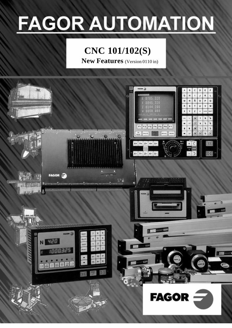
CNC 101/102(S)New Features (Version 0110 in)
- 2 -
ERRORS DETECTED IN THE INSTALLATION MANUAL (REF. 9703)Comparison table (page x). General characteristics.
In the "Axes" section" where it says "Axes X + Y + Auxiliary handwheel"It should say "X Axis + Auxiliary Y axis (not dro) + Auxiliary handwheel"
Comparison table (page xii). Programming.The programming function G34 is missing:
G34 X axis as an infinite follower of another axis (only for the 101S)
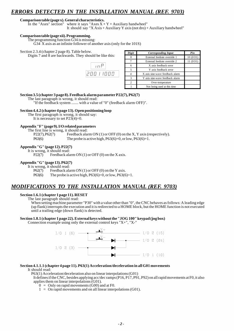
Section 2.3.4 (chapter 2 page 8). Table below.Digits 7 and 8 are backwards. They should be like this:
Section 3.5 (chapter 3 page 8). Feedback alarm parameter P22(7), P62(7)The last paragraph is wrong, it should read:
"If the feedback system ....... with a value of "0" (feedback alarm OFF)".
Section 4.4.2 (chapter 4 page 13). Open positioning loopThe first paragraph is wrong, it should say:
It is necessary to set P23(4)=0.
Appendix "F" (page 9). I/O related parametersThe first line is wrong, it should read:
P22(7), P62(7) Feedback alarm ON (1) or OFF (0) on the X, Y axis (respectively).P63(6) The probe is active high, P63(6)=0, or low, P63(6)=1.
Appendix "G" (page 12). P22(7)It is wrong, it should read:
P22(7) Feedback alarm ON (1) or OFF (0) on the X axis.
Appendix "G" (page 13). P62(7)It is wrong, it should read:
P62(7) Feedback alarm ON (1) or OFF (0) on the Y axis.P63(6) The probe is active high, P63(6)=0, or low, P63(6)=1.
MODIFICATIONS TO THE INSTALLATION MANUAL (REF. 9703)Section 1.6.1 (chapter 1 page 11). RESET
The last paragraph should read:When setting machine parameter "P30" with a value other than "0", the CNC behaves as follows: A leading edge(up flank) interrupts the execution and it is redirected to a HOME block, but the HOME function is not executeduntil a trailing edge (down flank) is detected.
Section 1.8.1 (chapter 1 page 22). External keys without the "JOG 100" keypad (jog box)Connection example using only the external control keys "X+", "X-"
Section 4.1.1.1 (chapter 4 page 11). P63(1) Acceleration/deceleration in all G01 movementsIt should read:
P63(1) Acceleration/deceleration also on linear interpolations (G01)It defines if the CNC, besides applying acc/dec ramps (P16, P17, P91, P92) on all rapid movements at F0, it alsoapplies them on linear interpolations (G01).
0 = Only on rapid movements (G00) and at F0.1 = On rapid movements and on all linear interpolations (G01).
Digit Corresponding Input Pin8 External feedrate override 1 10 (I/O1)7 External feedrate override 2 11 (I/O1)6 X axis feedback error5 Y axis feedback error4 X axis sine-wave feedback alarm3 Y axis sine-wave feedback alarm2 Over-temperature1 Not being used at this time
- 3 -
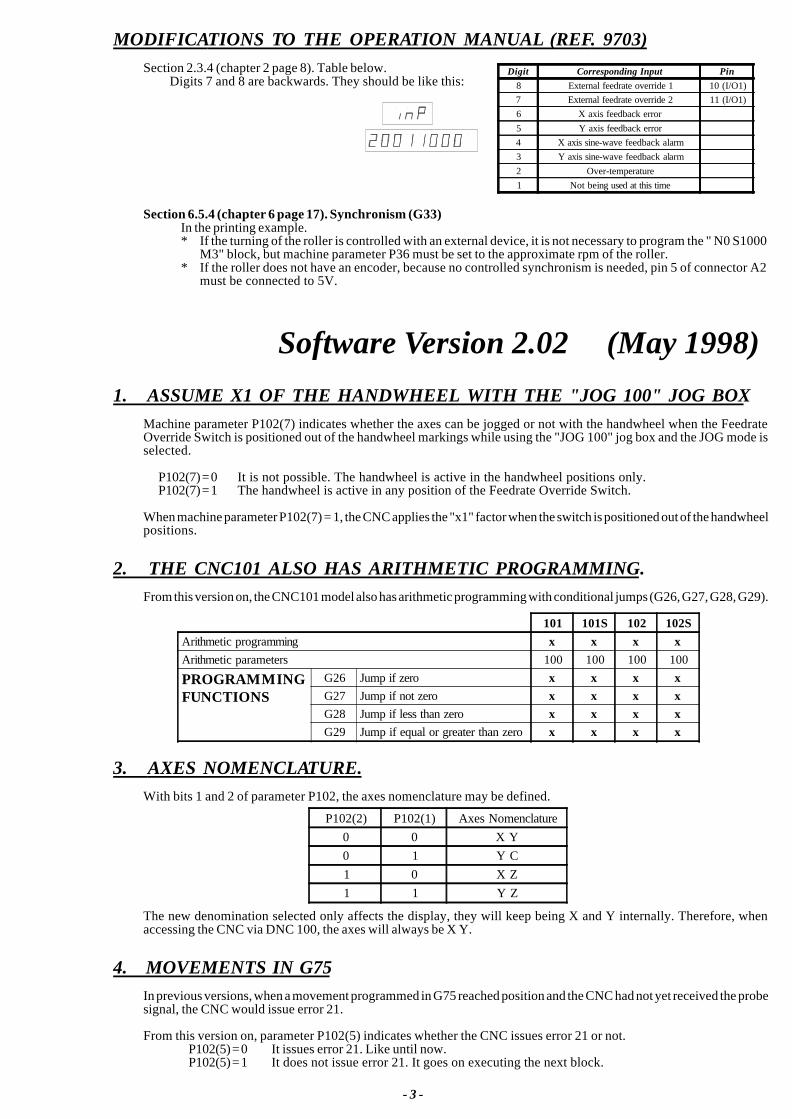
MODIFICATIONS TO THE OPERATION MANUAL (REF. 9703)Section 2.3.4 (chapter 2 page 8). Table below.
Digits 7 and 8 are backwards. They should be like this:
Section 6.5.4 (chapter 6 page 17). Synchronism (G33)In the printing example.* If the turning of the roller is controlled with an external device, it is not necessary to program the " N0 S1000
M3" block, but machine parameter P36 must be set to the approximate rpm of the roller.* If the roller does not have an encoder, because no controlled synchronism is needed, pin 5 of connector A2
must be connected to 5V.
Software Version 2.02 (May 1998)1. ASSUME X1 OF THE HANDWHEEL WITH THE "JOG 100" JOG BOX
Machine parameter P102(7) indicates whether the axes can be jogged or not with the handwheel when the FeedrateOverride Switch is positioned out of the handwheel markings while using the "JOG 100" jog box and the JOG mode isselected.
P102(7) = 0 It is not possible. The handwheel is active in the handwheel positions only.P102(7) = 1 The handwheel is active in any position of the Feedrate Override Switch.
When machine parameter P102(7) = 1, the CNC applies the "x1" factor when the switch is positioned out of the handwheelpositions.
2. THE CNC101 ALSO HAS ARITHMETIC PROGRAMMING.From this version on, the CNC101 model also has arithmetic programming with conditional jumps (G26, G27, G28, G29).
3. AXES NOMENCLATURE.With bits 1 and 2 of parameter P102, the axes nomenclature may be defined.
The new denomination selected only affects the display, they will keep being X and Y internally. Therefore, whenaccessing the CNC via DNC 100, the axes will always be X Y.
4. MOVEMENTS IN G75In previous versions, when a movement programmed in G75 reached position and the CNC had not yet received the probesignal, the CNC would issue error 21.
From this version on, parameter P102(5) indicates whether the CNC issues error 21 or not.P102(5) = 0 It issues error 21. Like until now.P102(5) = 1 It does not issue error 21. It goes on executing the next block.
P102(2) P102(1) Axes Nomenclature0 0 X Y0 1 Y C1 0 X Z1 1 Y Z
101 101S 102 102SArithmetic programming x x x xArithmetic parameters 100 100 100 100
PROGRAMMINGFUNCTIONS
G26 Jump if zero x x x xG27 Jump if not zero x x x xG28 Jump if less than zero x x x xG29 Jump if equal or greater than zero x x x x
Digit Corresponding Input Pin8 External feedrate override 1 10 (I/O1)7 External feedrate override 2 11 (I/O1)6 X axis feedback error5 Y axis feedback error4 X axis sine-wave feedback alarm3 Y axis sine-wave feedback alarm2 Over-temperature1 Not being used at this time
- 4 -
5. DISPLAY OF THE AXIS IN EXECUTIONIn previous versions, while in Automatic mode, the CNC could change the axis being displayed depending on themovement programmed:
If both axes move => it keeps displaying the axis selected with A+ ,A-If only the X axis moves => it displays the X axisIf only the Y axis moves => it displays the Y axis
From this version on, parameter P102(6) determines whether the CNC behaves like before or it does not change the axisbeing displayed.
P102(6) = 0 Like beforeP102(6) = 1 The CNC does not change the axis. It keeps displaying the axis selected with A+ ,A-
Software Version 2.03 (January 1999)1. ADDITIONAL MOVEMENT WITH G75
When probing at high speed, it could stop abruptly making the axis overshoot the programmed position and havingto move back into position.
In previous versions of the CNC 101 S, machine parameter P82 could be used to minimize this sometimes undesirableeffect.
This parameter indicates to the CNC the distance the axis must move after receiving the probe signal, thus stoppingsmoothly.
From this version on, this feature will also be available on the "102 S" CNC model and parameter P83 indicates the distancethe Y axis must move after receiving the probe signal.
Therefore: P82 indicates the distance the X axis must move after receiving the probe signal.P83 indicates the distance the Y axis must move after receiving the probe signal.
Possible values: From 1 to 65535 microns.From 1 to 25801 tenth-thousandths of an inch.
Software Version 2.05 (October 2001)1. OPERATION WITH 100-LINE HANDWHEELS (U.F.O.)
Until now, the CNC 101/102 was ready to operate with 25-line handwheels. It internally multiplies by 4 in order to obtain100 pulses per each turn of the handwheel.From this version on, it is also possible to use 100-line handwheels (Fagor UFO model handwheels)Set machine parameter P103(2)=1 so its pulses are not multiplied by 4.
This feature is only available when connecting the handwheel to the CNC's feedback input.The auxiliary handwheel, connected to the digital inputs of the CNC must always have 25 lines per turn.
Headquarters (SPAIN): Fagor Automation S. Coop.Bº San Andrés s/n, Apdo. 144E-20500 Arrasate - MondragónTel: (34)-943 71 92 00Fax: (34)-943 79 17 12 (34)-943 77 11 18 (Service Dept.)www.fagorautomation.comE-mail: [email protected]
101 / 101S CNC102 / 102S CNC
OPERATING MANUAL
9703 (ing)
The information described in this manual may be subject to variations due totechnical modifications.
FAGOR AUTOMATION, S. Coop. Ltda. reserves the right to modify thecontents of this manual without prior notice.
INDEX
Section Page
Comparison table for FAGOR CNC models: 101/101S/102/102S ...................................... ixNew Features and Modifications .......................................................................................... xiii
INTRODUCTION
Safety Conditions ................................................................................................................ 3Material Returning Terms .................................................................................................. 6Fagor Documentation for the 101/101S/102/102S CNC ................................................. 7Manual Contents ................................................................................................................. 8
Chapter 1 PERIPHERALS
1.1 Front panel description......................................................................................................... 11.2 Peripheral mode .................................................................................................................... 21.2.1 "1-Output" option. CNC --> peripheral ................................................................................ 31.2.2 "2-Input" option. Peripheral --> CNC ................................................................................... 4
Chapter 2 AUX MODE
2.1 System Input/Output test ...................................................................................................... 22.2 Machine parameters .............................................................................................................. 52.2.1 Editing machine parameters ................................................................................................. 52.3 Tool table or zero offset table ............................................................................................... 7
Chapter 3 JOG MODE
3.1 Jogging the axes ................................................................................................................... 13.2 Automatic positioning ......................................................................................................... 53.3 Zero setting or coordinate preset .......................................................................................... 53.4 Machine Reference (Home) search ....................................................................................... 63.4.1 Considerations about the machine reference zero (home) .................................................... 73.5 Operation of the CNC as a DRO ........................................................................................... 7
Section Page
Chapter 4 PROGRAM EDITING
4.1 Editing mode ........................................................................................................................ 14.1.1 Displaying block contents ................................................................................................... 34.1.2 Program editing .................................................................................................................... 44.1.3 Deleting Block contents ....................................................................................................... 64.1.4 Deleting the whole program memory ................................................................................... 64.1.5 Modifying block contents .................................................................................................... 74.1.6 Inserting a new program block ............................................................................................. 94.1.7 Eliminating empty blocks (memory compression) ............................................................... 94.2 Teach-in editing ................................................................................................................... 104.3 Play-back editing ................................................................................................................. 114.3.1 Reading points in Play-Back Mode ..................................................................................... 12
Chapter 5 PROGRAM EXECUTION
5.1 Program execution ................................................................................................................ 15.2 Program interruption ............................................................................................................ 25.3 Display modes ...................................................................................................................... 35.4 Display of the arithmetic parameters .................................................................................... 65.5 Change of operating mode ................................................................................................... 6
Chapter 6 PROGRAMMING
6.1 Programming format ............................................................................................................. 16.1.1 Preparatory G functions ........................................................................................................ 26.2 Basic concepts ...................................................................................................................... 36.2.1 Block number and conditional block (block skip) .............................................................. 36.2.2 Metric or inch programming (G70/G71) .............................................................................. 36.2.3 Absolute / incremental programming (G90/G91) ................................................................. 36.3 Reference systems ................................................................................................................. 56.3.1 Reference points ................................................................................................................... 56.3.2 Machine Reference (home) search (G74) ............................................................................. 66.3.3 Coordinate preset and zero offsets ........................................................................................ 76.3.3.1 Coordinate preset (G92) ....................................................................................................... 76.3.3.2 Zero offset loading (G51....G60) ........................................................................................... 86.3.3.3 Zero offset selection (T1 ... T10) ........................................................................................... 86.4 Complementary functions .................................................................................................... 96.4.1 Axis feedrate "F" ................................................................................................................... 96.4.2 Spindle speed "S" ................................................................................................................. 96.4.3 Tool number "T" ................................................................................................................... 106.4.4 Zero offset "T"....................................................................................................................... 106.4.5 Miscellaneous /auxiliary) "M" function ............................................................................... 106.5 Path control .......................................................................................................................... 126.5.1 Rapid positioning (G00) ...................................................................................................... 126.5.2 Linear interpolation (G01) ................................................................................................... 136.5.3 Circular interpolation (G02, G03) ........................................................................................ 146.5.4 Synchronization (G33) ......................................................................................................... 166.5.5 Axis X as an infinite slave of another axis (G34) ................................................................. 186.5.5.1 Automatic pass compensation .............................................................................................. 20
Section Page
6.6 Additional preparatory functions ......................................................................................... 216.6.1 Dwell (G04) .......................................................................................................................... 216.6.2 Increment part counter (G45) ................................................................................................ 216.6.3 Round corner (G05) and square corner (G07) ....................................................................... 226.7 Special functions .................................................................................................................. 236.7.1 Feedback inhibit (G47, G56) ................................................................................................ 236.7.2 G47, G48 as opening of the axis loop .................................................................................. 246.7.3 The feedrate "F" is not affected by "P18" (G61, G62) ........................................................... 256.7.4 Acceleration ramp modification (G93) ................................................................................. 256.8 Other functions ..................................................................................................................... 266.8.1 Batch programming (G81) .................................................................................................... 266.8.2 Probing (G75) ....................................................................................................................... 286.8.3 Rigid tapping (G84, G80) ..................................................................................................... 296.8.4 Loading the punch sizes (G60) ............................................................................................. 326.9 Parametric programming ...................................................................................................... 336.9.1 Assignments ......................................................................................................................... 336.9.2 Operations ............................................................................................................................ 346.9.3 Access to the arithmetic parameter table .............................................................................. 376.9.4 Unconditional jump function (G25) ..................................................................................... 396.9.5 Conditional jump functions (G26, G27, G28, G29) ............................................................. 41
ERROR CODES
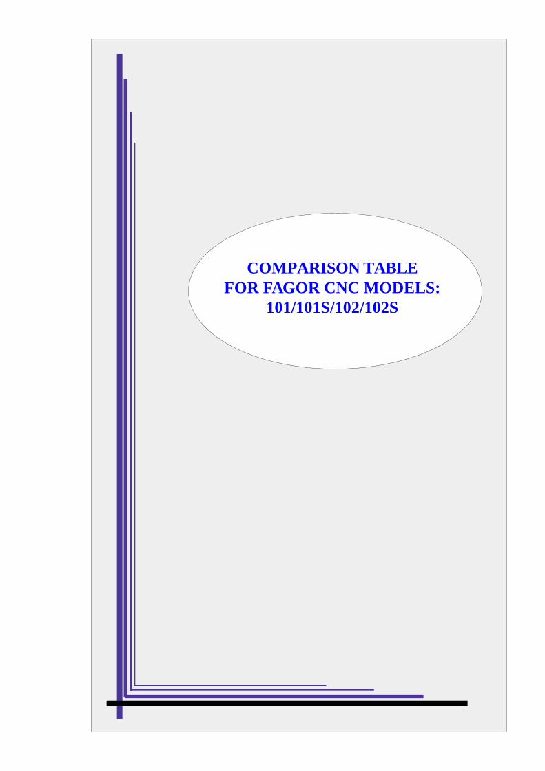
COMPARISON TABLEFOR FAGOR CNC MODELS:
101/101S/102/102S
GENERAL CARACTERISTICS
101 101S 102 102SFeedback inputs Connector A1 (X axis) x x x x
Connector A2 (Y axis) x x x
x5 multiplier circuit for sine-wave signals x x x
Feedback correction factor x x x xAnalog outputs X axis x x x x
Y axis x xSpindle (S) x x x x
Axes X axis x x x xX + Y axis x xX axis + electronic handwheel x x xAxes X + Y + auxiliary handwheel x x xDouble feedback for X axis x
Axis control Closed Loop x x x xOpen Loop x xRigid Tapping x
Interface with externaldevices
External operator panel "JOG 100" x xRS232C Interface x x xFagor Local Area Network (LAN) x x xDNC 100 x x
Operating options Overtemperature alarm x x xOperation in radius or diameter x x xOperation with a probe x x xZero offsets x x xTool length compensation x x xAcceleration / deceleration x x x x
INPUTS AND OUTPUTS
101 101S 102 102SINPUTS X axis home switch x x x x
Y axis home switch x x xExternal emergency stop x x x xFeedhold x x x xExternal Cycle Start x x x xExternal Cycle Stop x x x xConditional input (block skip) x x x xManual input (DRO mode) x x x xExternal Reset (initial CNC conditions) x x x x2 inputs as Handwheel multiplying factor JOG100 x JOG1002 inputs for Feedrate override JOG100 x JOG1005 inputs for parametric programming x x x2 inputs for handling the auxiliary handwheel x x x
OUTPUTS 8 outputs for M, S or T in BCD or decoded x x x xM Strobe x x x xS Strobe x x xT Strobe x x xJOG mode selected at the CNC x x x xAutomatic mode selected at the CNC x x xInternal CNC emergency x x x xX axis brake x x x xY axis brake x xX axis in position x x x xY axis in position x xX axis Fast (Non-servocontrolled open loop) x JOG 100 x JOG 100X axis Slow (Non-servocontrolled open loop) x JOG 100 x JOG 100X direction (Non-servocontrolled open loop) x JOG 100 x JOG 100Y axis Fast (Non-servocontrolled open loop) JOG 100 x JOG 100Y axis Slow (Non-servocontrolled open loop) xY direction (Non-servocontrolled open loop) x
PROGRAMMING101 101S 102 102S
Number of blocks 900 900 900 900Conditional blocks (block skip) x x x xParts counter x x x xArithmetic programming x x xArithmetic parameters 100 100 100
PROGRAMMIFUNCTIONS
G00 Rapid positioning x x x xG01 Linear interpolation x x x xG02 Clockwise circular interpolation x xG03 Counter-clockwise circular interpolation x xG04 Dwell x x x xG05 Round corner x x x xG07 Square corner x x x xG25 Unconditional jump x x x xG26 Jump if zero x x xG27 Jump if not zero x x xG28 Jump if less than zero x x xG29 Jump if equal or greater than zero x x xG33 Synchronization xG45 Increment part-counter's count x x x xG47 Pulse inhibit x x xG48 Cancel function G47 x x x
G51 to G60 Load zero offset x x xG61 F not affected by "P18" x x x xG62 Cancel function G61 x x x xG70 Inch programming x x x xG71 Metric programming x x x xG74 Machine Reference (home) search x x x xG75 Probing x x xG81 Batch programming x x
G84, G80 Rigid tapping xG90 Absolute coordinate programming x x x xG91 Incremental coordinate programming x x x xG92 Coordinate presetting x x x xG93 Modification of acceleration ramp x x x
NEW FEATURESAND
MODIFICATIONS
Date: March 1997 Software Version: 2.1 and newer
FEATURE AFFECTED MANUAL AND SECTION
Synchronization of movements (G33) Operating Manual Section 6.5.4
Axis X as infinite slave of another axis (G34) Installation Manual Section 5.5Operating Manual Section 6.5.5
G47, G48 as axis loop opener Installation Manual Section 5.7Operating Manual Section 6.7.2
G75 special function Installation Manual Section 5.6
Travel limit control taking into account the Installation Manual Section 5.8the punch radius Operating Manual Section 6.8.4
Selection of the Arithmetical Parameters Installation Manual Section 3.7which are required for display. Operating Manual Section 6.9.3
Play-Back, as reading points. Installation Manual Section 3.6Operating Manual Section 4.3.1
Parametrical programming takes the S Installation Manual Sect. 5.1 and 6.7sign into account
The axes can be denominated Y, C Installation Manual Section 3.4
Auxiliary Handwheel handling by Installation Manual Sect. 1.7, 3.4 andmeans of 2 digital inputs Operating Manual Section 3.1
Braking Control in open loop Installation Manual Section 4.4.2
Reading / Writing of machine parametersfrom the DNC100
Error elimination by external Reset.

Introduction - 1
INTRODUCTION
Introduction - 3
SAFETY CONDITIONS
Read the following safety measures in order to prevent damage to personnel, to thisproduct and to those products connected to it.
This unit must only be repaired by personnel authorized by Fagor Automation.
Fagor Automation shall not be held responsible for any physical or material damagederived from the violation of these basic safety regulations.
Precautions against personal damage
Use proper Mains AC power cablesTo avoid risks, use only the Mains AC cables recommended for this unit.
Avoid electrical overloadsIn order to avoid electrical discharges and fire hazards, do not apply electrical voltageoutside the range selected on the rear panel of the Central Unit.
Ground connectionIn order to avoid electrical discharges, connect the ground terminals of all the modulesto the main ground terminal. Before connecting the inputs and outputs of this unit, makesure that all the grounding connections are properly made.
Before powering the unit up, make sure that it is connected to groundIn order to avoid electrical discharges, make sure that all the grounding connections areproperly made.
Do not work in humid environmentsIn order to avoid electrical discharges, always work under 90% of relative humidity(non-condensing) and 45º C (113º F).
Do not work in explosive environmentsIn order to avoid risks, damage, do not work in explosive environments.
Precautions against product damage
Working environmentThis unit is ready to be used in Industrial Environments complying with the directivesand regulations effective in the European Community
Fagor Automation shall not be held responsible for any damage suffered or causedwhen installed in other environments (residential or homes).
Install the unit in the right placeIt is recommended, whenever possible, to instal the CNC away from coolants, chemicalproduct, blows, etc. that could damage it.
This unit complies with the European directives on electromagnetic compatibility.Nevertheless, it is recommended to keep it away from sources of electromagneticdisturbance such as.
Introduction - 4
- Powerful loads connected to the same AC power line as this equipment.- Nearby portable transmitters (Radio-telephones, Ham radio transmitters).- Nearby radio / TC transmitters.- Nearby arc welding machines- Nearby High Voltage power lines- Etc.
EnclosuresThe manufacturer is responsible of assuring that the enclosure involving the equipmentmeets all the currently effective directives of the European Community.
Avoid disturbances coming from the machine toolThe machine-tool must have all the interference generating elements (relay coils,contactors, motors, etc.) uncoupled.
Use the proper power supplyUse an external regulated 24 Vdc power supply for the inputs and outputs.
Grounding of the power supplyThe zero volt point of the external power supply must be connected to the main groundpoint of the machine.
Analog inputs and outputs connectionIt is recommended to connect them using shielded cables and connecting their shields(mesh) to the corresponding pin (See chapter 2).
Ambient conditionsThe working temperature must be between +5° C and +45° C (41ºF and 113º F)The storage temperature must be between -25° C and 70° C. (-13º F and 158º F)
Monitor enclosureAssure that the Monitor is installed at the distances indicated in chapter 1 from the wallsof the enclosure.
Use a DC fan to improve enclosure ventilation.
Main AC Power SwitchThis switch must be easy to access and at a distance between 0.7 m (27.5 inches) and1.7 m (5.6 ft) off the floor.
Protections of the unit itself
It carries two fast fuses of 3.15 Amp./ 250V. to protect the mains AC input.
All the digital inputs and outputs have galvanic isolation via optocouplers between theCNC circuitry and the outside.
They are protected by an external fast fuse (F) of 3.15 Amp./ 250V. against over voltageand reverse connection of the power supply.
The type of fuse depends on the type of monitor. See the identification label of the unit.
Introduction - 5
Precautions during repair
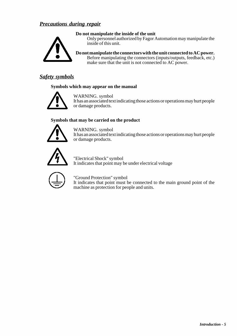
Do not manipulate the inside of the unitOnly personnel authorized by Fagor Automation may manipulate theinside of this unit.
Do not manipulate the connectors with the unit connected to AC power.Before manipulating the connectors (inputs/outputs, feedback, etc.)make sure that the unit is not connected to AC power.
Safety symbols
Symbols which may appear on the manual
WARNING. symbolIt has an associated text indicating those actions or operations may hurt peopleor damage products.
Symbols that may be carried on the product
WARNING. symbolIt has an associated text indicating those actions or operations may hurt peopleor damage products.
"Electrical Shock" symbolIt indicates that point may be under electrical voltage
"Ground Protection" symbolIt indicates that point must be connected to the main ground point of themachine as protection for people and units.
Introduction - 6
MATERIAL RETURNING TERMS
When returning the CNC, pack it in its original package and with its original packagingmaterial. If not available, pack it as follows:
1.- Get a cardboard box whose three inside dimensions are at least 15 cm (6 inches) largerthan those of the unit. The cardboard being used to make the box must have a resistanceof 170 Kg (375 lb.).
2.- When sending it to a Fagor Automation office for repair, attach a label indicating theowner of the unit, person to contact, type of unit, serial number, symptom and a briefdescription of the problem.
3.- Wrap the unit in a polyethylene roll or similar material to protect it.
When sending the monitor, especially protect the CRT glass.
4.- Pad the unit inside the cardboard box with poly-utherane foam on all sides.
5.- Seal the cardboard box with packing tape or industrial staples.
Introduction - 7
FAGOR DOCUMENTATIONFOR THE 101/101S / 102/102S CNC
101/101S / 102/102S CNC OEM Manual
Is directed to the machine builder or person in charge of installing and startingup the CNC.
It has the Installation manual inside. Sometimes, it may contain an additionalmanual describing New Software Features recently implemented.
101/101S / 102/102S CNC USER Manual
Is directed to the end user or CNC operator.
It contains the Operating manual.Sometimes, it may contain an additional manual describing New SoftwareFeatures recently implemented.
Introduction - 8
MANUAL CONTENTS
The installation manual consists of the following sections:
Index
Comparative Table for Fagor 101/101S / 102/102S CNC models
Introduction Safety ConditionsShipping conditionsFagor documents for the 101/101S / 102/102S CNCManual Contents
Chapter 1 Peripherials
Chapter 2 Aux mode
Chapter 3 Jog mode
Chapter 4 Program editing
Chapter 5 Program execution
Chapter 6 Programming
Error Codes
PERIPHERALS 1
Chapter: 1 Section: Page
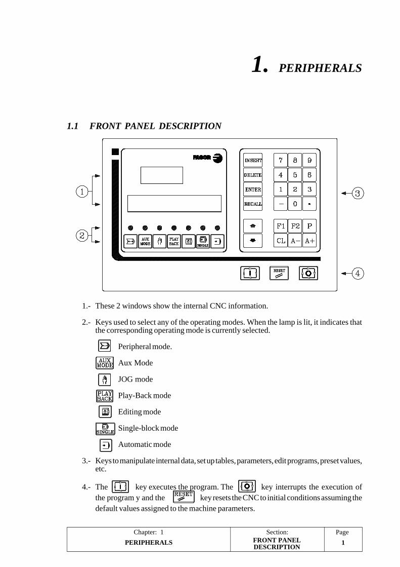
1. PERIPHERALS
1.1 FRONT PANEL DESCRIPTION
1.- These 2 windows show the internal CNC information.
2.- Keys used to select any of the operating modes. When the lamp is lit, it indicates thatthe corresponding operating mode is currently selected.
Peripheral mode.
Aux Mode
JOG mode
Play-Back mode
Editing mode
Single-block mode
Automatic mode
3.- Keys to manipulate internal data, set up tables, parameters, edit programs, preset values,etc.
4.- The key executes the program. The key interrupts the execution ofthe program y and the key resets the CNC to initial conditions assuming thedefault values assigned to the machine parameters.
FRONT PANELDESCRIPTION
PERIPHERALS2
Section:Chapter: 1Page
1.2 PERIPHERAL MODE
In order to access this operating mode, machine parameter "P100(1)" must be set to "0"indicating that the DNC feature is not available.
With this operating mode, it is possible to transfer part-programs, machine-parameters andthe tool table out to a peripheral device (cassette reader FAGOR LS80, PC, terminal, etc.)through the RS232C serial line
To do this, the machine parameters corresponding to the RS232C serial line must be setaccordingly:
P70 Communications speed (baudrate) in baud.P59(7) Number of data bits.P59(5) ParityP59(6) Even or Odd parityP59(8) Number of stop bits
Bear in mind that the CNC must be off when connecting or disconnecting any peripheraldevice to it.
To access the peripheral mode, press the key.
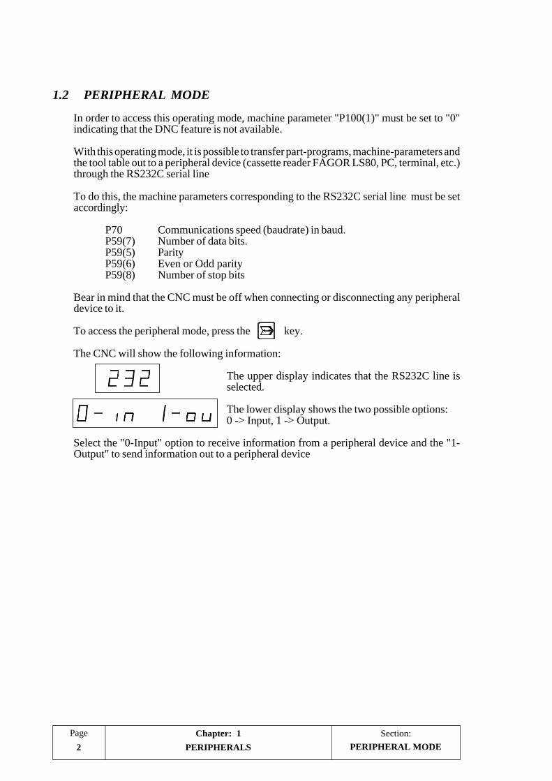
The CNC will show the following information:
The upper display indicates that the RS232C line isselected.
The lower display shows the two possible options:0 -> Input, 1 -> Output.
Select the "0-Input" option to receive information from a peripheral device and the "1-Output" to send information out to a peripheral device
PERIPHERAL MODE
PERIPHERALS 3
Chapter: 1 Section: Page
1.2.1 "1-OUTPUT" OPTION. CNC --> PERIPHERAL
This option must be selected once the peripheral device has been set ready to receive.
The lower CNC display will show the letter "N".
Depending on what has to be transmitted, proceed as follows:
a) To send the machine parameter table and tool table or zero offset table.
Press the following keystroke sequence: [8] [9] [9] [A-]
The transmitted data is illegible and must be used as a back-up copy either to be sentback to the CNC later on or to another similar CNC.
b) To send the whole content of the part-program memory, that is from N000 to blockN899, out to a peripheral:
Press: [A+]
c) To transmit the contents of the part-program memory starting at a particular blocknumber:
Press the number of the first block to be transmitted and, then, press [A+].
For example, The keystroke sequence: [1] [0] [0] [A+] will send blocks N100 and allthe following ones out to the peripheral.
d) To transmit a particular set of blocks of the part-program memory:
Indicate the first and last blocks to be transmitted separated by a period and press [A+].
For example, the keystroke sequence: [2] [0] [0] [.] [2] [2] [0] [A+] will send all theblocks between N200 and N220 (both included).
The CNC format to send each block consists of 3 digits indicating the block number, theblock contents and the Carriage Return (RT) and Line Feed (LF) characters indicating theend of the block.
Once all the blocks have been sent, the CNC sends the ESCAPE character indicating theend of transmission.
Example: 012 G01.91 X130 Y-56.3 F200 RT LF013 X17.9 M6 RT LF
- -
369 M30 RT LF ESC
The transmission can be aborted at any time by pressing [CL].
PERIPHERAL MODE
PERIPHERALS4
Section:Chapter: 1Page
1.2.2 "0-INPUT" OPTION. PERIPHERAL -->CNC
In order to send part-programs, machine parameter table, tool table or the zero offset table,the CNC memory must be unlocked.
When selecting this option, the lower display of the CNC will show the letter "N".
Depending on what has to be transmitted, proceed as follows:
a) To receive at the CNC the machine parameter table, tool table or the zero offset table:
Press the keystroke sequence: [8] [9] [9] [A-] at the CNC and give the order to transmitat the peripheral device.
b) To read a program which already has its block numbered:
Press [A+].
The program is loaded into the CNC memory with those block numbers.
Those blocks not involved in the transmission will keep their original data.
c) To read a program not having its blocks numbered:
Indicate the starting block number from which it must be loaded into the CNC memoryand press [A+].
For example: the keystroke sequence [1] [5] [0] [A+] indicates that those blocks mustbe loaded starting at block number N150. The rest of the blocks will be correlative (therewill be no empty blocks).
Those blocks not involved in the transmission (the ones before the first block and afterthe last one) will keep their original data.
The format to be used at the peripheral to send each program block to the CNC must consistof:
3 digits indicating the block number (optional)The block contentsThe Return (RT) and Line feed (LF) characters indicating the end of block.
Once all the blocks have been sent to the CNC, the ESCAPE character must be sent as endof transmission.
The transmission may be aborted at any time by pressing [CL].
PERIPHERAL MODE
AUX MODE 1
Chapter: 2 Section: Page
2. AUX MODE
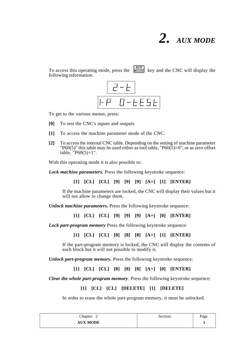
To access this operating mode, press the key and the CNC will display thefollowing information.
To get to the various menus, press:
[0] To test the CNC's inputs and outputs
[1] To access the machine parameter mode of the CNC.
[2] To access the internal CNC table. Depending on the setting of machine parameter"P60(5)" this table may be used either as tool table, "P60(5)=0", or as zero offsettable, "P60(5)=1".
With this operating mode it is also possible to:
Lock machine parameters. Press the following keystroke sequence:
[1] [CL] [CL] [9] [9] [9] [A+] [1] [ENTER]
If the machine parameters are locked, the CNC will display their values but itwill not allow to change them.
Unlock machine parameters. Press the following keystroke sequence:
[1] [CL] [CL] [9] [9] [9] [A+] [0] [ENTER]
Lock part-program memory Press the following keystroke sequence:
[1] [CL] [CL] [8] [8] [8] [A+] [1] [ENTER]
If the part-program memory is locked, the CNC will display the contents ofeach block but it will not possible to modify it.
Unlock part-program memory. Press the following keystroke sequence:
[1] [CL] [CL] [8] [8] [8] [A+] [0] [ENTER]
Clear the whole part-program memory. Press the following keystroke sequence:
[1] [CL] [CL] [DELETE] [1] [DELETE]
In order to erase the whole part-program memory, it must be unlocked.
AUX MODE2
Section:Chapter: 2Page
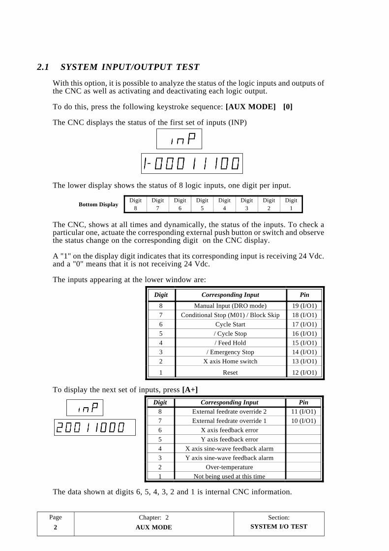
2.1 SYSTEM INPUT/OUTPUT TEST
With this option, it is possible to analyze the status of the logic inputs and outputs ofthe CNC as well as activating and deactivating each logic output.
To do this, press the following keystroke sequence: [AUX MODE] [0]
The CNC displays the status of the first set of inputs (INP)
The lower display shows the status of 8 logic inputs, one digit per input.
The CNC, shows at all times and dynamically, the status of the inputs. To check aparticular one, actuate the corresponding external push button or switch and observethe status change on the corresponding digit on the CNC display.
A "1" on the display digit indicates that its corresponding input is receiving 24 Vdc.and a "0" means that it is not receiving 24 Vdc.
The inputs appearing at the lower window are:
To display the next set of inputs, press [A+]
The data shown at digits 6, 5, 4, 3, 2 and 1 is internal CNC information.
Bottom DisplayDigit
8Digit
7Digit
6Digit
5Digit
4Digit
3Digit
2Digit
1
SYSTEM I/O TEST
Digit Corresponding Input Pin
8 Manual Input (DRO mode) 19 (I/O1)7 Conditional Stop (M01) / Block Skip 18 (I/O1)6 Cycle Start 17 (I/O1)5 / Cycle Stop 16 (I/O1)4 / Feed Hold 15 (I/O1)3 / Emergency Stop 14 (I/O1)2 X axis Home switch 13 (I/O1)
1 Reset 12 (I/O1)
Digit Corresponding Input Pin8 External feedrate override 2 11 (I/O1)7 External feedrate override 1 10 (I/O1)6 X axis feedback error5 Y axis feedback error4 X axis sine-wave feedback alarm3 Y axis sine-wave feedback alarm2 Over-temperature1 Not being used at this time
AUX MODE 3
Chapter: 2 Section: Page
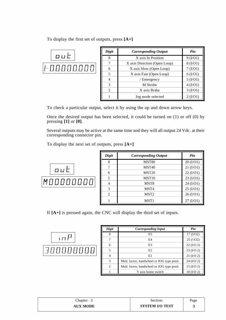
To display the first set of outputs, press [A+]
To check a particular output, select it by using the up and down arrow keys.
Once the desired output has been selected, it could be turned on (1) or off (0) bypressing [1] or [0].
Several outputs may be active at the same time and they will all output 24 Vdc. at theircorresponding connector pin.
To display the next set of outputs, press [A+]
If [A+] is pressed again, the CNC will display the third set of inputs.
SYSTEM I/O TEST
Digit Corresponding Input Pin
8 E5 17 (I/O2)
7 E4 25 (!/O2)
6 E3 22 (I/O 2)
5 E2 23 (I/O 2)
4 E1 21 (I/O 2)
3 Mult. factor, handwheel or JOG type posit. 24 (I/O 2)
2 Mult. factor, handwheel or JOG type posit. 15 (I/O 2)
1 Y axis home switch 18 (I/O 2)
Digit Corresponding Output Pin
8 X axis In Position 9 (I/O1)7 X axis Direction (Open Loop) 8 (I/O1)6 X axis Slow (Open Loop) 7 (I/O1)5 X axis Fast (Open Loop) 6 (I/O1)4 / Emergency 5 (I/O1)3 M Strobe 4 (I/O1)2 X axis Brake 3 (I/O1)
1 Jog mode selected 2 (I/O1)
Digit Corresponding Output Pin
8 MST80 20 (I/O1)7 MST40 21 (I/O1)6 MST20 22 (I/O1)5 MST10 23 (I/O1)4 MST8 24 (I/O1)3 MST4 25 (I/O1)2 MST2 26 (I/O1)
1 MST1 27 (I/O1)
AUX MODE4
Section:Chapter: 2Page
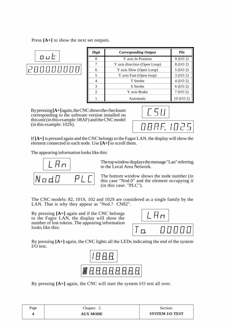
Press [A+] to show the next set outputs.
By pressing [A+] again, the CNC shows the checksumcorresponding to the software version installed onthis unit (in this example: 08AF) and the CNC model(in this example: 102S).
If [A+] is pressed again and the CNC belongs to the Fagor LAN, the display will show theelement connected to each node. Use [A+] to scroll them.
The appearing information looks like this:
The top window displays the message "Lan" referringto the Local Area Network.
The bottom window shows the node number (inthis case "Nod.0" and the element occupying it(in this case: "PLC").
The CNC models: 82, 101S, 102 and 102S are considered as a single family by theLAN. That is why they appear as "Nod.? CN82".
By pressing [A+] again and if the CNC belongsto the Fagor LAN, the display will show thenumber of lost tokens. The appearing informationlooks like this:
By pressing [A+] again, the CNC lights all the LEDs indicating the end of the systemI/O test.
By pressing [A+] again, the CNC will start the system I/O test all over.
SYSTEM I/O TEST
Digit Corresponding Output Pin
8 Y axis In Position 9 (I/O 2)7 Y axis direction (Open Loop) 8 (I/O 2)6 Y axis Slow (Open Loop) 5 (I/O 2)5 Y axis Fast (Open loop) 3 (I/O 2)4 T Strobe 4 (I/O 2)3 S Strobe 6 (I/O 2)2 Y axis Brake 7 (I/O 2)
1 Automatic 10 (I/O 2)
AUX MODE 5
Chapter: 2 Section: Page
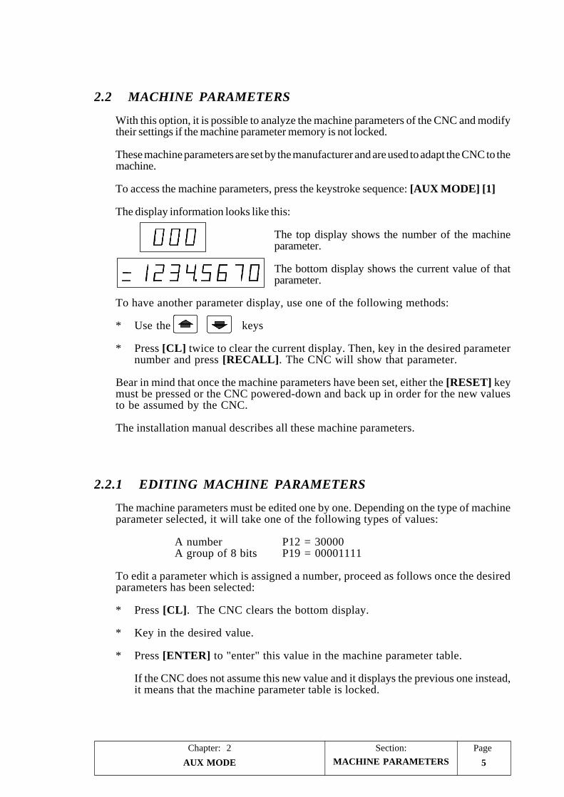
2.2 MACHINE PARAMETERS
With this option, it is possible to analyze the machine parameters of the CNC and modifytheir settings if the machine parameter memory is not locked.
These machine parameters are set by the manufacturer and are used to adapt the CNC to themachine.
To access the machine parameters, press the keystroke sequence: [AUX MODE] [1]
The display information looks like this:
The top display shows the number of the machineparameter.
The bottom display shows the current value of thatparameter.
To have another parameter display, use one of the following methods:
* Use the keys
* Press [CL] twice to clear the current display. Then, key in the desired parameternumber and press [RECALL]. The CNC will show that parameter.
Bear in mind that once the machine parameters have been set, either the [RESET] keymust be pressed or the CNC powered-down and back up in order for the new valuesto be assumed by the CNC.
The installation manual describes all these machine parameters.
2.2.1 EDITING MACHINE PARAMETERS
The machine parameters must be edited one by one. Depending on the type of machineparameter selected, it will take one of the following types of values:
A number P12 = 30000A group of 8 bits P19 = 00001111
To edit a parameter which is assigned a number, proceed as follows once the desiredparameters has been selected:
* Press [CL]. The CNC clears the bottom display.
* Key in the desired value.
* Press [ENTER] to "enter" this value in the machine parameter table.
If the CNC does not assume this new value and it displays the previous one instead,it means that the machine parameter table is locked.
MACHINE PARAMETERS
AUX MODE6
Section:Chapter: 2Page
To edit a parameter defined with a group of 8 bits, once it has been selected, press[CL] and enter the 8 bits or press [RECALL] and change the bits one by one.
To change the bits one by one, proceed as follows:
* Press [RECALL]. The display will blink the first parameter bit.
* To change this bit , press [0] or [1] accordingly.
* Use the keys to move from bit to bit (making them blink).
* To change a particular bit, select it by making it blink and set it to the desiredvalue.
* Once all the bits have been set, press [ENTER] for this value to be entered in themachine parameter memory.
If the CNC does not assume this new value and it displays the previous one instead,it means that the machine parameter table is locked.
To enter all 8 bits at once, proceed as follows:
* If the parameter was selected by using the [RECALL] key, the CNC will blinkthe first parameter bit (editing mode).
To quit this mode, press [CL] and the bit will stop blinking.
* Press [CL] again and the bottom display will clear out.
* Key in the desired value (series of 1s and 0s).
* Press [ENTER] so this new value is "entered" in the machine parameter table.
If the CNC does not assume this new value and it displays the previous one instead,it means that the machine parameter table is locked.
MACHINE PARAMETERS
AUX MODE 7
Chapter: 2 Section: Page
2.3 TOOL TABLE OR ZERO OFFSET TABLE
The CNC has an internal table which, depending on the setting of machine parameter"P60(5)", may be used as tool table, "P60(5)=0", or zero offset table, "P60(5)=1".
Each one of 10 table addresses (1 through 10) has 2 fields: one for the X axis andthe other one for the Y axis.
When setting "P60(5)=0", tool table, the address number matches the tool number.Both fields indicate tool length along X and Y (respectively). The CNC will take thetable values and will apply tool length along both axes.
When setting "P60(5)=1", zero offset table, each table address can be allocated a newPart Zero. This part zero will be referred to Machine Reference Zero (home) at thedistance indicated in the Y and Y fields.
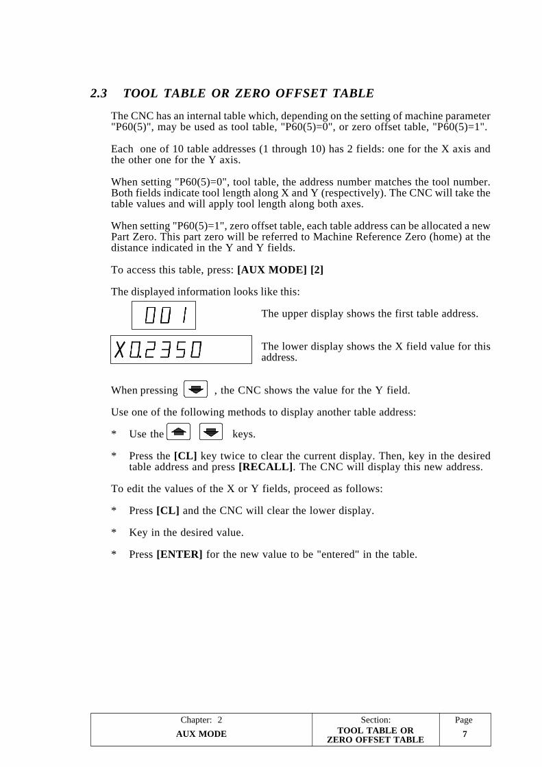
To access this table, press: [AUX MODE] [2]
The displayed information looks like this:
The upper display shows the first table address.
The lower display shows the X field value for thisaddress.
When pressing , the CNC shows the value for the Y field.
Use one of the following methods to display another table address:
* Use the keys.
* Press the [CL] key twice to clear the current display. Then, key in the desiredtable address and press [RECALL]. The CNC will display this new address.
To edit the values of the X or Y fields, proceed as follows:
* Press [CL] and the CNC will clear the lower display.
* Key in the desired value.
* Press [ENTER] for the new value to be "entered" in the table.
TOOL TABLE ORZERO OFFSET TABLE
PageChapter: 3 Section:
JOG MODE 1
3. JOG MODE
To access this mode, press the key. The top display will appear blank and thebottom one will show the X axis position.
To change the axis being displayed, press [A+]. The lower display will now show the Yaxis position.
With this operating mode it is possible to:
Move the axes of the machine.Set Zero or preset a coordinate value (position).Automatically search home (machine referencing)Select the CNC to operate as a DRO.
3.1 JOGGING THE AXES
The CNC may be configured in the following ways:
CNC with 1 or 2 axes.CNC with 1 axis and 1 electronic handwheel.CNC with 1 or 2 axes and the external operator panel "JOG 100".CNC with 1 axis, 1 electronic handwheel and the external operator panel "JOG100".CNC with 2 axes and auxiliary handwheelCNC with 2 axes, auxiliary handwheel and the external operator panel "JOG 100"
When moving the axes, the CNC limits their travels according to the setting of machineparameters P0, P1, P40 and P41.
CNC with 1 or 2 axes
The axes are jogged one at a time. To do that, proceed as follows:
* Select at the lower display, by using the [A+] key, the axis to be jogged (X or Y).
* Use the keys to jog the axis.
The movement will be continuous. In other words, the axis will keep moving while itsjog key is kept pressed.
If pins 14 and 25 of connector I/O2 are used the movements could be continuous orincremental. In incremental movements the axis will move the predetermined distance.
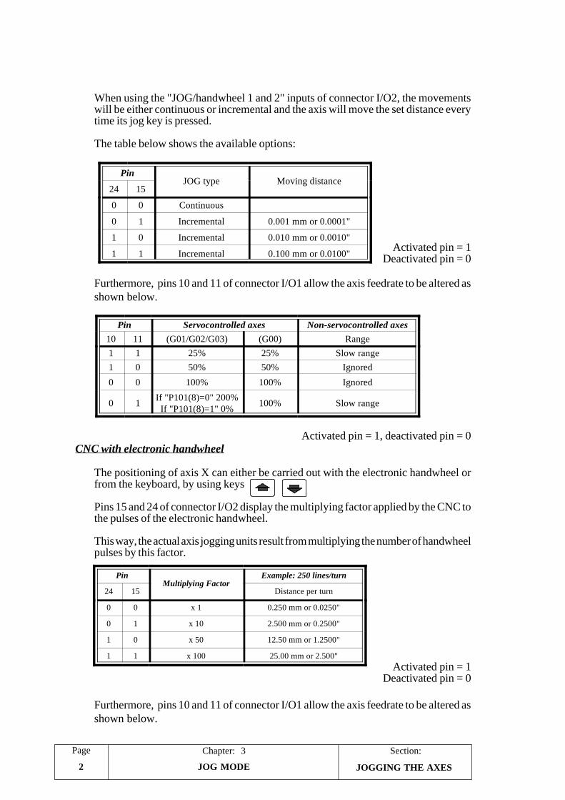
JOGGING THE AXES
Section:Chapter: 3Page
JOG MODE2 JOGGING THE AXES
PinJOG type Moving distance
24 15
0 0 Continuous
0 1 Incremental 0.001 mm or 0.0001"
1 0 Incremental 0.010 mm or 0.0010"
1 1 Incremental 0.100 mm or 0.0100"
Pin Servocontrolled axes Non-servocontrolled axes10 11 (G01/G02/G03) (G00) Range1 1 25% 25% Slow range1 0 50% 50% Ignored
0 0 100% 100% Ignored
0 1 If "P101(8)=0" 200%If "P101(8)=1" 0% 100% Slow range
PinMultiplying Factor
Example: 250 lines/turn
24 15 Distance per turn
0 0 x 1 0.250 mm or 0.0250"
0 1 x 10 2.500 mm or 0.2500"
1 0 x 50 12.50 mm or 1.2500"
1 1 x 100 25.00 mm or 2.500"
When using the "JOG/handwheel 1 and 2" inputs of connector I/O2, the movementswill be either continuous or incremental and the axis will move the set distance everytime its jog key is pressed.
The table below shows the available options:
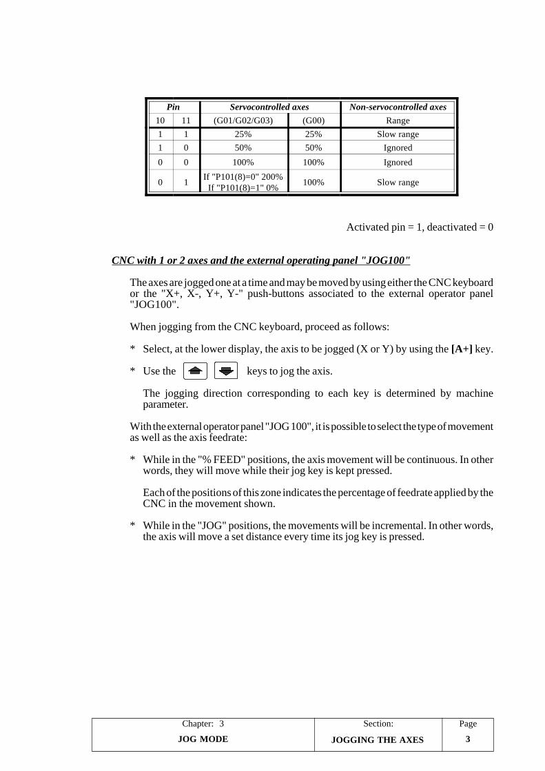
Activated pin = 1Deactivated pin = 0
Furthermore, pins 10 and 11 of connector I/O1 allow the axis feedrate to be altered asshown below.
Activated pin = 1, deactivated pin = 0CNC with electronic handwheel
The positioning of axis X can either be carried out with the electronic handwheel orfrom the keyboard, by using keys
Pins 15 and 24 of connector I/O2 display the multiplying factor applied by the CNC tothe pulses of the electronic handwheel.
This way, the actual axis jogging units result from multiplying the number of handwheelpulses by this factor.
Activated pin = 1Deactivated pin = 0
Furthermore, pins 10 and 11 of connector I/O1 allow the axis feedrate to be altered asshown below.
PageChapter: 3 Section:
JOG MODE 3
Activated pin = 1, deactivated = 0
CNC with 1 or 2 axes and the external operating panel "JOG100"
The axes are jogged one at a time and may be moved by using either the CNC keyboardor the "X+, X-, Y+, Y-" push-buttons associated to the external operator panel"JOG100".
When jogging from the CNC keyboard, proceed as follows:
* Select, at the lower display, the axis to be jogged (X or Y) by using the [A+] key.
* Use the keys to jog the axis.
The jogging direction corresponding to each key is determined by machineparameter.
With the external operator panel "JOG 100", it is possible to select the type of movementas well as the axis feedrate:
* While in the "% FEED" positions, the axis movement will be continuous. In otherwords, they will move while their jog key is kept pressed.
Each of the positions of this zone indicates the percentage of feedrate applied by theCNC in the movement shown.
* While in the "JOG" positions, the movements will be incremental. In other words,the axis will move a set distance every time its jog key is pressed.
JOGGING THE AXES
Pin Servocontrolled axes Non-servocontrolled axes10 11 (G01/G02/G03) (G00) Range1 1 25% 25% Slow range1 0 50% 50% Ignored
0 0 100% 100% Ignored
0 1 If "P101(8)=0" 200%If "P101(8)=1" 0% 100% Slow range
Section:Chapter: 3Page
JOG MODE4 JOGGING THE AXES
CNC with 1 axis, 1 electronic handwheel and the external operator panel "JOG 100"
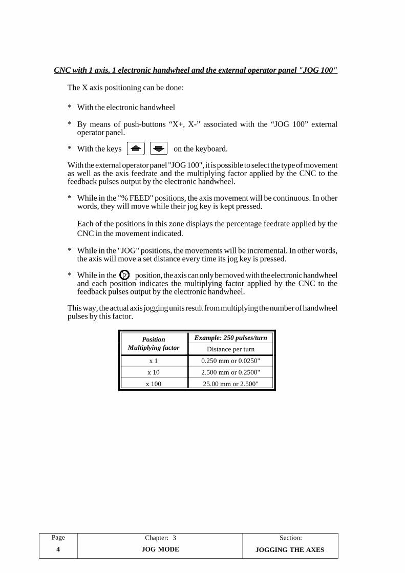
The X axis positioning can be done:
* With the electronic handwheel
* By means of push-buttons “X+, X-” associated with the “JOG 100” externaloperator panel.
* With the keys on the keyboard.
With the external operator panel "JOG 100", it is possible to select the type of movementas well as the axis feedrate and the multiplying factor applied by the CNC to thefeedback pulses output by the electronic handwheel.
* While in the "% FEED" positions, the axis movement will be continuous. In otherwords, they will move while their jog key is kept pressed.
Each of the positions in this zone displays the percentage feedrate applied by theCNC in the movement indicated.
* While in the "JOG" positions, the movements will be incremental. In other words,the axis will move a set distance every time its jog key is pressed.
* While in the position, the axis can only be moved with the electronic handwheeland each position indicates the multiplying factor applied by the CNC to thefeedback pulses output by the electronic handwheel.
This way, the actual axis jogging units result from multiplying the number of handwheelpulses by this factor.
PositionMultiplying factor
Example: 250 pulses/turn
Distance per turn
x 1 0.250 mm or 0.0250"
x 10 2.500 mm or 0.2500"
x 100 25.00 mm or 2.500"

PageChapter: 3 Section:
JOG MODE 5
3.2 AUTOMATIC POSITIONING
It is carried out one axis at a time by following these steps:
* Select, at the lower display, the axis to be positioned (X or Y) by means of the [A+]key.
* Press [CL] to clear the lower display.
* Key in the desired destination coordinate (position).
* Press
The CNC will position the axis at the indicated position.
3.3 ZERO SETTING OR COORDINATE PRESET
The coordinate preset is performed one axis at a time by following these steps:
* Select at the lower display, with the [A+] key, the axis to be preset (X or Y).
* Press [CL] to clear the display.
* Key in the desired position value (coordinate).
* Press [ENTER] for the CNC to assume this value.
Press [CL] to cancel this preset before pressing [ENTER] if so desired. In this case,the CNC will display the previous value again.
AUTOMATIC POSITIONINGAND PRESET
Section:Chapter: 3Page
JOG MODE6
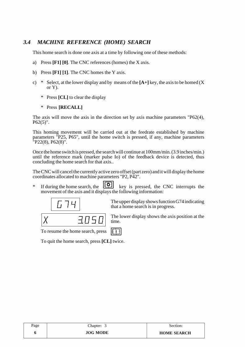
3.4 MACHINE REFERENCE (HOME) SEARCH
This home search is done one axis at a time by following one of these methods:
a) Press [F1] [0]. The CNC references (homes) the X axis.
b) Press [F1] [1]. The CNC homes the Y axis.
c) * Select, at the lower display and by means of the [A+] key, the axis to be homed (Xor Y).
* Press [CL] to clear the display
* Press [RECALL]
The axis will move the axis in the direction set by axis machine parameters "P62(4),P62(5)".
This homing movement will be carried out at the feedrate established by machineparameters "P25, P65", until the home switch is pressed, if any, machine parameters"P22(8), P62(8)".
Once the home switch is pressed, the search will continue at 100mm/min. (3.9 inches/min.)until the reference mark (marker pulse Io) of the feedback device is detected, thusconcluding the home search for that axis..
The CNC will cancel the currently active zero offset (part zero) and it will display the homecoordinates allocated to machine parameters "P2, P42".
* If during the home search, the key is pressed, the CNC interrupts themovement of the axis and it displays the following information:
The upper display shows function G74 indicatingthat a home search is in progress.
The lower display shows the axis position at thetime.
To resume the home search, press
To quit the home search, press [CL] twice.
HOME SEARCH
PageChapter: 3 Section:
JOG MODE 7
3.4.1 CONSIDERATIONS ABOUT THE MACHINE REFERENCEZERO (HOME)
* If when initiating the home search, the home switch is pressed, the axis will move in theopposite direction to the one determined by machine parameters "P62(4), P62(5)", untilthe home switch is released and, then, it will start the home search.
* If the axis is positioned outside the travel limits specified by machine parameters "P0, P1,P40 and P41", the axis must be jogged by hand into the work area and, then, positionit in the appropriate area for homing it.
* If the selected axis does not have a home switch installed, machine parameters "P22(8)"and "P62(8)"), only the marker pulse searching move at 100 mm/min will be carried outuntil the marker pulse (Io) of the feedback device is detected, thus concluding the homesearch.
3.5 OPERATION OF THE CNC AS A DRO
When the Manual (DRO) input at pin 19 of connector I/O1 is set high (24 Vdc), the CNCbehaves like a DRO.
This means that:
* That the axes must be moved by means external to the CNC.
* The axis enable signals must be deactivated so they can be moved freely.
* If when operating in this mode, the axis travel limits set by machine parameters P0, P1,P40 and P41 are overrun, the CNC will issue the corresponding error message.
HOME SEARCHAND DRO MODE
PageChapter: 4 Section:
PROGRAM EDITING 1
4. PROGRAM EDITING
This CNC offers three program editing modes as described in this chapter and they are:
Regular editing. Press to access this mode.
Teach-in editing. Press to access this mode.
Play-back editing. Press to access this mode.
4.1 EDITING MODE
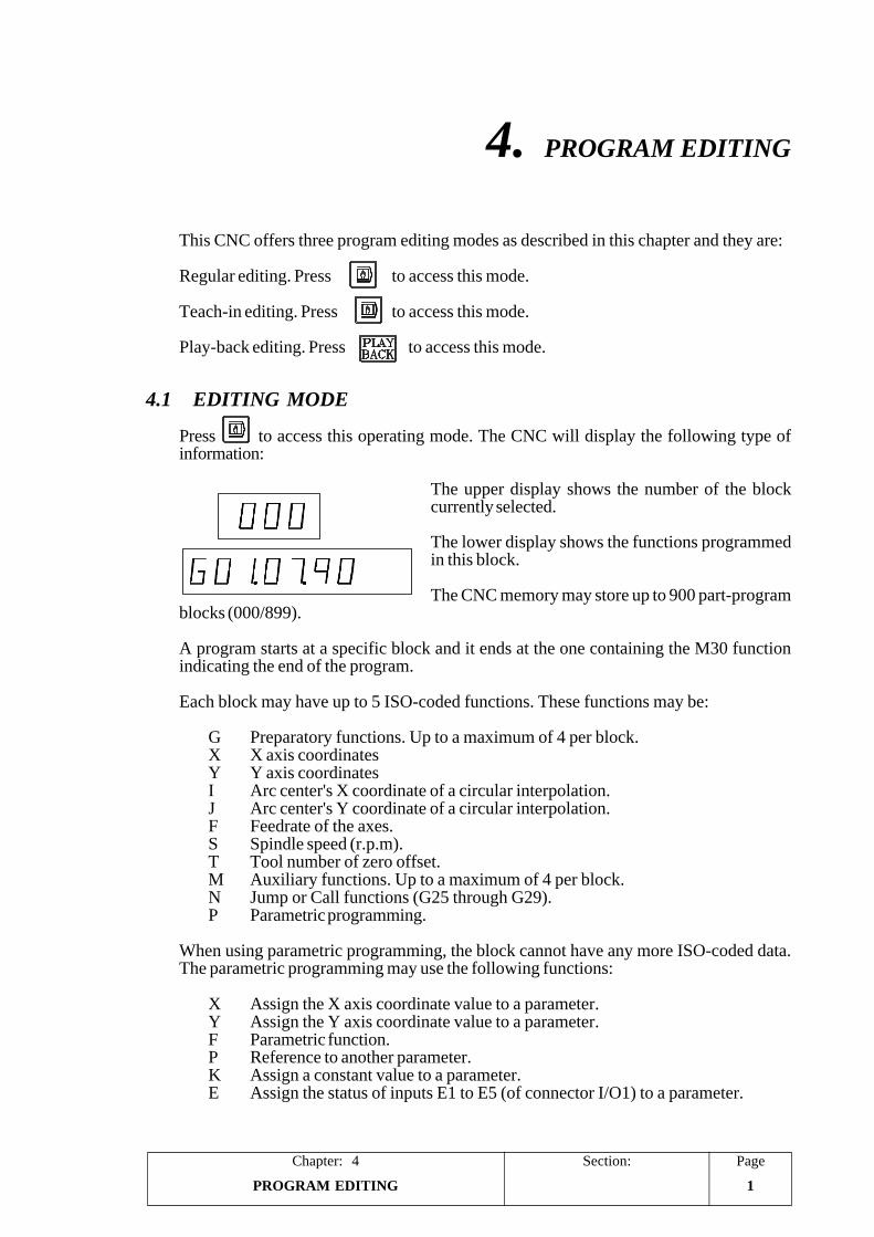
Press to access this operating mode. The CNC will display the following type ofinformation:
The upper display shows the number of the blockcurrently selected.
The lower display shows the functions programmedin this block.
The CNC memory may store up to 900 part-programblocks (000/899).
A program starts at a specific block and it ends at the one containing the M30 functionindicating the end of the program.
Each block may have up to 5 ISO-coded functions. These functions may be:
G Preparatory functions. Up to a maximum of 4 per block.X X axis coordinatesY Y axis coordinatesI Arc center's X coordinate of a circular interpolation.J Arc center's Y coordinate of a circular interpolation.F Feedrate of the axes.S Spindle speed (r.p.m).T Tool number of zero offset.M Auxiliary functions. Up to a maximum of 4 per block.N Jump or Call functions (G25 through G29).P Parametric programming.
When using parametric programming, the block cannot have any more ISO-coded data.The parametric programming may use the following functions:
X Assign the X axis coordinate value to a parameter.Y Assign the Y axis coordinate value to a parameter.F Parametric function.P Reference to another parameter.K Assign a constant value to a parameter.E Assign the status of inputs E1 to E5 (of connector I/O1) to a parameter.
Section:Chapter: 4Page
PROGRAM EDITING2
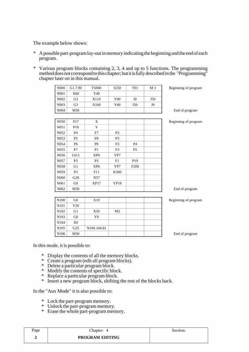
The example below shows:
* A possible part-program lay-out in memory indicating the beginning and the end of eachprogram.
* Various program blocks containing 2, 3, 4 and up to 5 functions. The programmingmethod does not correspond to this chapter; but it is fully described in the "Programming"chapter later on in this manual.
In this mode, it is possible to:
* Display the contents of all the memory blocks.* Create a program (edit all program blocks).* Delete a particular program block.* Modify the contents of specific block.* Replace a particular program block.* Insert a new program block, shifting the rest of the blocks back.
In the "Aux Mode" it is also possible to:
* Lock the part-program memory.* Unlock the part-program memory.* Erase the whole part-program memory.
N000 G1.7.90 F5000 S250 T01 M 3 Beginning of programN001 X60 Y40N002 G3 X110 Y90 I0 J50N003 G3 X160 Y40 I50 J0N004 M30 End of program
N050 P17 X Beginning of programN051 P18 YN052 P4 F7 P3N053 P5 F8 P3N054 P6 P0 F3 P4N055 P7 P1 F3 P5N056 G0.5 XP6 YP7N057 P3 P3 F1 P19N058 G1 XP6 YP7 F200N059 P3 F11 K360N060 G28 N57N061 G0 XP17 YP18N062 M30 End of program
N100 G0 X10 Beginning of programN101 Y20N102 G1 X50 M3N103 G0 Y0N104 X0N105 G25 N100.104.81N106 M30 End of program
PageChapter: 4 Section:
PROGRAM EDITING 3
4.1.1 DISPLAYING BLOCK CONTENTS
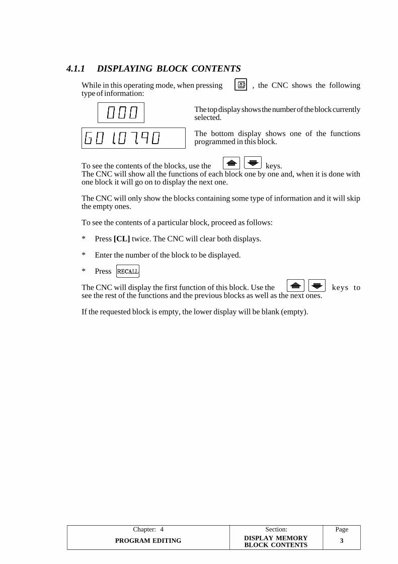
While in this operating mode, when pressing , the CNC shows the followingtype of information:
The top display shows the number of the block currentlyselected.
The bottom display shows one of the functionsprogrammed in this block.
To see the contents of the blocks, use the keys.The CNC will show all the functions of each block one by one and, when it is done withone block it will go on to display the next one.
The CNC will only show the blocks containing some type of information and it will skipthe empty ones.
To see the contents of a particular block, proceed as follows:
* Press [CL] twice. The CNC will clear both displays.
* Enter the number of the block to be displayed.
* Press
The CNC will display the first function of this block. Use the keys tosee the rest of the functions and the previous blocks as well as the next ones.
If the requested block is empty, the lower display will be blank (empty).
DISPLAY MEMORYBLOCK CONTENTS
Section:Chapter: 4Page
PROGRAM EDITING4
4.1.2 PROGRAM EDITING
A program is edited one block at a time starting from the first block. To do this proceed asfollows:
1.- If the selected block (appearing at the top display) is not the desired one, do thefollowing:
* Press [CL] twice to clear both displays.
* Enter the desired block number.
* Press [RECALL]
2.- If the block is not empty (bottom display), do the following:
* Press [CL] once to clear the bottom display (block contents).
3.- Edit the block contents by defining all its functions. Use the [A+] and [A-] keys to selectthese functions.
The way to program a block is fully described in the "Programming" chapter later onin this manual.
Once the whole block has been edited, press [ENTER]. The CNC will show the nextblock.
Example: N000 G1.7.90 F5000 T1
* Select the block number N000 at the upper display. Make sure the block is empty(blank), if not empty, press [CL].
* Press [A+]. The block number at the upper display starts to blinks (block editingmode).
The lower display shows the first function that may be selected. The "G"character corresponds to a G function.
* Key in "1.7.90" which correspond to G01, G07 and G90.
* Press [A+] and the CNC will display the next available function which, in thiscase, is "X".
* Press [A+] and [A-] until the lower display shows the "F" character whichcorresponds to the "F" function (feedrate).
* Key in "5000", corresponding to a feedrate value of F5000.
* Press [A+] and the CNC will show the next available function which, in this case,is the "S" function (spindle).
* Press [A+] and [A-] until the lower display shows the "T" character correspondingto the "T" function (tool).
PROGRAM EDITING
PageChapter: 4 Section:
PROGRAM EDITING 5
* Key in [1], number of the tool to be selected T1.
* Press [ENTER], The CNC concludes the editing of the block and the upperdisplay will show the next block number without blinking. In this case is block"001".
4.- Repeat the operations described in the previous procedure to edit the rest of the blocks.
Attention:
While editing a block, if when pressing [A+] or [A-] the CNC does not showany more functions, it means that the block does not admit any more functionseither because of the type of block it is or because all the permitted ones havealready been defined (a maximum 5 functions).
The block numbers need not be sequential nor contain all the possibleinformation.
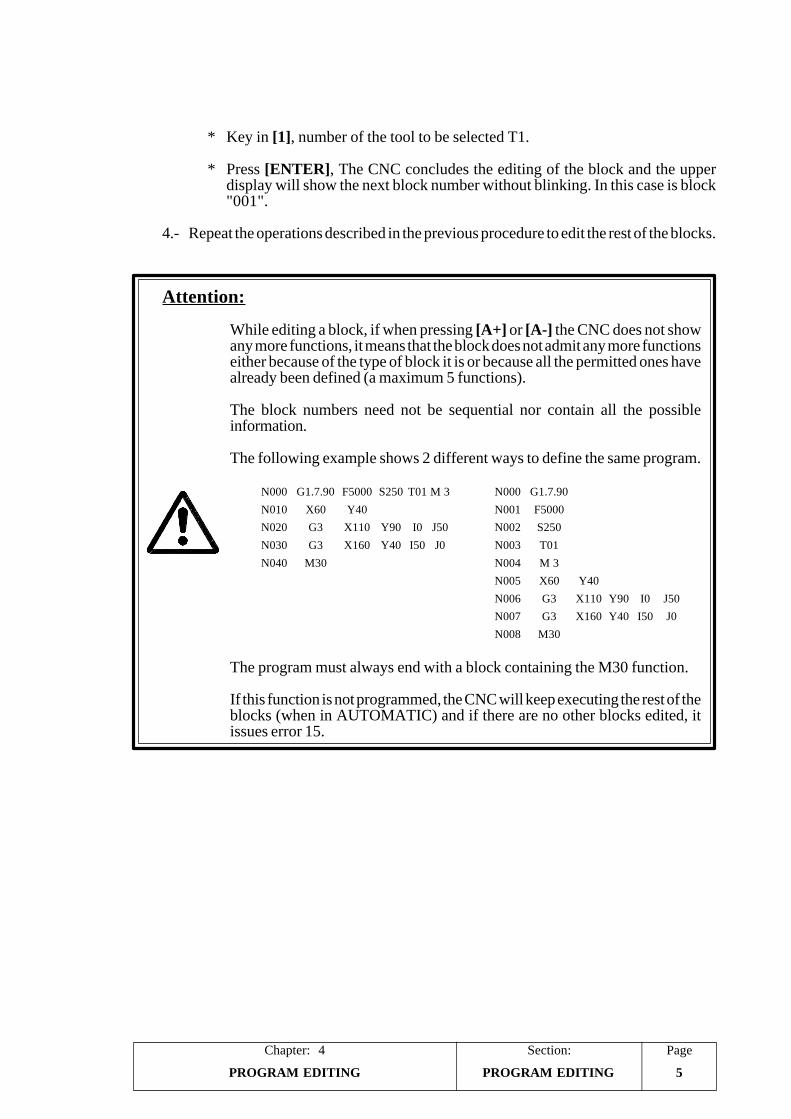
The following example shows 2 different ways to define the same program.
The program must always end with a block containing the M30 function.
If this function is not programmed, the CNC will keep executing the rest of theblocks (when in AUTOMATIC) and if there are no other blocks edited, itissues error 15.
PROGRAM EDITING
N000 G1.7.90 F5000 S250 T01 M 3 N000 G1.7.90N010 X60 Y40 N001 F5000N020 G3 X110 Y90 I0 J50 N002 S250N030 G3 X160 Y40 I50 J0 N003 T01N040 M30 N004 M 3
N005 X60 Y40N006 G3 X110 Y90 I0 J50N007 G3 X160 Y40 I50 J0N008 M30
Section:Chapter: 4Page
PROGRAM EDITING6
4.1.3 DELETING BLOCK CONTENTS
Two cases may occur when attempting to delete the contents of a program block:
1.- The currently selected block number (upper display) is not desired one. Proceed asfollows:
* Press [CL] twice to clear both displays.
* Enter the desired block number and...
* Press [DELETE].
2.- The currently selected block is the desired one. The upper display may be blinking(insert mode) or not. In either case...
* Press [DELETE]
In both instances, the block will stay selected but empty (the lower display being blank).When scrolling the program blocks, this block will no longer be displayed.
4.1.4 DELETING THE WHOLE PROGRAM MEMORY
When you wish to delete the whole program memory take the following steps:
* Press key to access the Aux-Mode operation mode.
* Press the following key sequence:
[1] [CL] [CL] [DELETE] [1] [DELETE]
To be able to delete the program memory this has to be unlocked.
BLOCK DELETE
PageChapter: 4 Section:
PROGRAM EDITING 7
4.1.5 MODIFYING BLOCK CONTENTS
If the currently selected block number is blinking (editing mode), press [CL] twice to quitthis mode.
When modifying the contents of a program block, the following cases may come up:
a) We would like to change the value of a function.
Example, modify a coordinate value:Current block: N000 G1.7.90 X100 F1000New block: N000 G1.7.90 X250 F1000
* Select block N000 and press [RECALL]. The upper display blinks this blocknumber.
* Use the keys to position at function "X100".
* Press [CL]. The CNC erases the value of the function; but it keeps its indicatorcharacter (X).
* Key in the desired value which, in this case, is "250".
* Press [ENTER] so the CNC assumes the new block.
b) We would like to eliminate one of the functions defining the block.
Example, eliminate the X coordinate:Current block: N000 G1.7 X100 Y20 F1000New block: N000 G1.7 Y20 F1000
* Select block N000 and press [RECALL]. The upper display blinks this blocknumber.
* Use the keys to position at "X100".
* Press [CL] twice to clear the lower display.
* Press [ENTER] for the CNC to assume the new block.
c) We would like to change a function.
Example, replace the X coordinate with Y:Current block: N000 G1 X100 F1000 M33New block: N000 G1 Y120 F1000 M33
* Select block N000 and press [RECALL]. The upper display will blink this blocknumber.
* Use the keys to position at "X100".
* Press [CL] twice so the CNC clears the lower display.
BLOCK MODIFICATION
Section:Chapter: 4Page
PROGRAM EDITING8
* Press [A+] and [A-] to select the new function which, in this case, is "Y".
* Key in the new value which, in this case, is "120".
* Press [ENTER] for the CNC to assume this new block.
Attention:
To change more than 2 functions on the same block, proceed as follows:
· Modify the first function.· Press to find the next function.· Modify the other function.· Press [ENTER] for the CNC to assume these changes.
The CNC does not assume the changes until [ENTER] is pressed.
If when pressing [ENTER], the block number keeps blinking (top display),it means that there is an error in the edited block and it is not accepted intomemory.
BLOCK MODIFICATION
PageChapter: 4 Section:
PROGRAM EDITING 9
4.1.6 INSERTING A NEW PROGRAM BLOCK
To insert a new block into a previously edited program, proceed as when editing blocks; butinstead of pressing [ENTER], press [INSERT].
The new edited block is inserted into memory shifting the ones behind it one position back.
Example: To insert block N051 containing function "G4.2".
Current program New program
N050 G90.71 N050 G90.71N051 G74 N051 G4.2N052 X-15.363 N052 G74N053 M9.6 N053 X-15.363
N054 M9.6
* Select block N051 and press [CL] to clear the lower display.
* Edit the block contents. Use [A+] to select the "G" function and key in the value:"4.2".
* Press [INSERT]. The CNC assumes the new block and "pushes" the followingones back one position.
If the block insertion affects blocks containing jump or call functions (G25 to G29), theCNC will take them into consideration and will update them accordingly.
4.1.7 ELIMINATING EMPTY BLOCKS (MEMORY COMPRESSION)
To eliminate an empty block, first select the block number and, then, press [INSERT]. TheCNC will shift ("pull") all the following blocks one position forward.
Example: To eliminate N152 and N153 which are empty.
Current program New program
N151 X12 Y13 F500 S1000 M3 N151 X12 Y13 F500 S1000 M3N154 M40 N152 M40N155 X20 Y0 N153 X20 Y0
* Select block N152 and press [INSERT]. The CNC "pulls" the following blocks upone position.
* Press [INSERT] again to shift them up one more position.
If the block elimination affects blocks containing jump or call functions (G25 to G29), theCNC will take them into consideration and will update them accordingly.
INSERTING / ELIMINATINGA PROGRAM BLOCK
Section:Chapter: 4Page
PROGRAM EDITING10
4.2 TEACH-IN EDITING
Press to access this operating mode.
In this programming mode, it is possible to execute the program blocks as they are beingedited before entering them into memory. It is also possible to execute functions ormovements outside the program.
To do this, once the block has been edited, press
The CNC will execute the block. When it is executed (blinking block number), thefollowing keys may be used:
[ENTER] To enter this block into memory. The CNC will now be ready for the next blockto be edited.
[CL]. The block will not be entered into memory being possible to modify it or editit.
The CNC will execute the block again.
With Teach-in programming, it is possible to run a part one block at a time as it is beingprogrammed (edited) since the CNC keeps the history of all the executed blocks.
For example, when executing block N100 G1.5.90 X100 F1000, the CNC assumes ashistory functions G1, G5, G90 and F1000. In other words, it is the same to executeafterwards N101 X120 or block N101 G1.5.90 X120 F1000.
Attention:
Teach-in programming allows executing blocks as they are being edited. Forthis reason, care must be taken before pressing and make sure thatthe block number appearing on the upper display is blinking. If it is notblinking, press [RECALL].
It is not possible to execute, in this mode, blocks containing jump functions(G25 to G29). The CNC will issue error 1 when attempting to execute them.
TEACH-IN EDITING
PageChapter: 4 Section:
PROGRAM EDITING 11
4.3 PLAY-BACK EDITING
Press to access this operating mode.
In this editing mode and while editing a block, it is possible to jog the axes to the desiredpoint and then enter the coordinate values reached as program data.
The rest of the functions are edited as described for the Editing mode earlier in this chapter.
The following example shows how to program a block of the G1 X___ Y___ F100 type.
The screen displays field "G"
- Press key [1] and then key [A+] to go on to the next field.
The screen shows field "X"
- Press key [Recall] and the CNC will display the present position of axis X.- Move the axis to the required position by means of the electronic handwheel, keys
or push-buttons "X+, X- associated with the "JOG100" external
operator panel.
- Press key [Enter] for the CNC to assume this value.- Press key [A+] to go on to the next field.
The screen displays field "Y"
- Press key [Recall] and the CNC will display the present position of axis X.- Move the axis to the required position by means of the electronic handwheel, keys
or push-buttons "Y+, Y- associated with the external "JOG100"
operator panel.
- Press key [Enter] for the CNC to assume this value.- Press key [A+] to go on to the next field.
The screen displays field "F"
- Move the axis to the required point- Press the keys [l] [0] [0]- Press key [Enter] for the CNC to assume this value and take the block as having
finished
PLAY-BACK EDITING
Section:Chapter: 4Page
PROGRAM EDITING12
4.3.1 READING POINTS IN PLAY-BACK MODE
The CNC allows points to be read in Play-Back mode more easily than the way shownabove
N100 X___ Y___N101 X___ Y___N102 X___ Y___N103 X___ Y___
To do this define parameter "P100(5)=1" and take the following steps
After pressing and selecting the block number:
The screen displays the field "X"
- Move the axis to the point required.- Press key [A+] or the external "Y+", "Y- " push-buttons for the CNC to assume
this value and go on to the following field .
The screen displays field "Y"
- Move the axis to the required point- Press key [Enter] or external push-button "Start" for the CNC to assume this value
and transfer the block to its memory.
The CNC increments the block number and the screen displays field "X".
- Repeat the aforementioned operations.
Attention:
In models with 2 axes available, the blocks are always stored in memorywith the coordinates of both axes (X___ Y___ ).
PLAY-BACK EDITING
PageChapter: 5 Section:
PROGRAM EXECUTION 1
5. PROGRAM EXECUTION
This CNC offers 2 program execution modes. The Automatic mode to run the wholeprogram all the way through the last block and the Single Block mode to run it block byblock requiring the pressing of the key to execute each block.
Press to select the "Single-Block" mode.
Press to select the "Automatic" mode.
Depending on the setting of machine parameter "P23(3)", the execution will be eitherAutomatic, "P23(3)=0", or Semi-automatic, "P23(3)=1".
When operating in Semi-automatic mode, whenever the CNC runs into a block whichcontains a movement, it interrupts the program execution and waits for the key tobe pressed or for the external Cycle Start input to be activated (pin 17 of connector I/O1)before resuming the execution of the program..
All three operating modes, Single Block, Fully Automatic and Semi-Automatic, aredescribed next.
5.1 PROGRAM EXECUTION
To execute a program, follow these steps:
1.- Select the desired operating mode, Single Block or Automatic.
2.- To select the first program block do the following:
* Press [CL] twice to clear both displays.
* Enter the desired block number.
* Press [RECALL].
3.- Press or activate the external Cycle Start input, pin 17 of connector I/O1, tobegin running the program.
4.- During the execution of the program, it is possible to vary the feedrate of the axes byusing the external operator panel "JOG100" or, when not available, the "Feedrateoverride" inputs (pins 10 and 11 of connector I/O1).
While the program is running, it is also possible to change the execution mode fromAutomatic to Single-Block and vice versa.
PROGRAM EXECUTION
Section:Chapter: 5Page
PROGRAM EXECUTION2
5.2 PROGRAM INTERRUPTION
The program is interrupted whenever:
is pressed
The external Cycle Stop input is activated, pin 16 of connector I/O1.
The CNC executes the M00 function (program stop).
The conditional input (pin 18 of connector I/O1) is active when executing function M01(conditional stop).
The external Feed-hold is active, pin 15 of connector I/O1. The CNC will continueexecuting the program when feed-hold is released (deactivated).
When the program execution is interrupted, the CNC stops the execution of the block andit allows to:
* Change the mode of execution. From Automatic to Single Block and vice-versa.
* Quit the execution mode and select another operating mode.
* Analyze the contents of previous and following blocks by using
Regardless of the block being displayed, the CNC "remembers" the block where theprogram was interrupted and it resumes execution from that block on.
* Select another block to resume the execution of the program from that block on.
Press [CL] twice, enter the desired block number and press [RECALL].
* Etc.
To resume program execution, press or activate the external Cycle Start input,pin 17 of connector I/O1.
The execution of the program ends when:
The CNC executes function M30. code indicating the end of the program with returnto the first block of the program.
The external Emergency Stop signal is activated (pin 14 of connector I/O1). The CNCissues the corresponding error and program must be executed from the beginning.
Attention:
It must be borne in mind that if machine parameter "P30" is set with a valuesmaller than 900; when activating the Reset input (pin 12 of connector I/O1)the CNC interrupts the execution of the program and starts executing from theblock number indicated by machine parameter "P30".
PROGRAM INTERRUPTION
PageChapter: 5 Section:
PROGRAM EXECUTION 3
5.3 DISPLAY MODES
Once the program is running, the lower display shows the X axis position. It is possible toselect the type of information to appear at the lower display by using the [A+] and [A-] keys.
The possible options are:
X 12345.678 X axis position value (coordinate)Y 12345.678 Y axis position valueM 3.41. M functions currently activeCon = 60 Number of parts (counter count)G 1.5.91. G functions currently activeE 0.012 Amount of X axis lag (following error)e 0.025 Amount of Y axis lag (following error)F 01000 Axis feedrate FN 010.025.12 Execution status of a callS 0250 T01 S value and tool number or zero offset currently active
Display of the position of the axes (X 12345.678 Y 12345.678)
It indicates the position of the axes at all times. Depending on the setting of machineparameter "P23(1)" this value may correspond to the theoretical axis coordinate,"P23(1)=1", or to the real one, "P23(1)=0".
Display of the M functions currently active (M3.41)
It displays the auxiliary M functions active at the time, even the M00, M01 or M30functions.
The M functions that may be displayed are:
M00, M01, M30 Related to stopping the programM03, M04, M05 Related to starting and stopping the spindleM41, M42, M43, M44 Related to changing spindle ranges (gears)
When pressing [RESET] or activating the external Reset input (pin 12 of connector I/O1), the CNC assumes the initial conditions and generates function M30.
Display of the parts-counter count (Con= 60)
The CNC increments this counter in one unit in the following instances:
* Every time function G45 is executed.
* Every time function M30 is executed while machine parameter "P21(4) = 1".
To reset the counter count to "0", select this display mode and, while the program is notrunning, press [DELETE].
The maximum count value is 9999. Beyond this value, the counts rolls over starting at0, 1, 2 and so forth.
DISPLAY MODES
Section:Chapter: 5Page
PROGRAM EXECUTION4
While executing function G81 (batch programming), the lower display shows theletters "Con" followed by the number of parts programmed for that batch and the righthand side of the display shows the number of parts already executed.
Display of the currently active G functions (G 1.5.91.)
The G functions that may be displayed are:
G01, G02, G03 Function G00 is not displayedG05 G07 is not displayedG70 G71 is not displayedG91 G90 is not displayed
Functions: G04, G25, G26, G27, G28, G29, G45, G74, G75, G92 are not displayed
Display of the axis lag (following error) (E 0.012, e 0.025)
This display mode is mainly used when setting the machine up to help adjust the axesof the machine.
They display the amount of following error (lag); that is, the difference between thetheoretical position of the axes (where they should be) and their real position (wherethey actually are).
Display of the feedrate of the axes (F 01000)
It displays the axis feedrate being applied at the time. That is, the programmed feedrateF multiplied by the % override.
DISPLAY MODES
PageChapter: 5 Section:
PROGRAM EXECUTION 5
Display of the execution status of a call (N 010.025.12)
The CNC uses this display mode when executing a jump function: G25, G26, G27,G28 or G29.
When not executing this type of function, it displays the following information:
N ---.---.--
When executing a jump function, the CNC executes the indicated program section anumber of times. The information appearing at the lower display looks like this:
N 050 . 120 . 16
The first 3-digit figure (050, in this example) indicates the number of the first blockbeing executed repeatedly.
The second 3-digit number (120, in this example) indicates the number of the lastblock being executed repeatedly.
The third figure (2 digits. 16, in this example) indicates the number of repetitions leftfor the program section being executed repeatedly.
Display of the selected spindle speed "S" and table (S 0250 T01)
It displays the spindle speed "S" currently selected as well as the "T" table addresscurrently selected.
Depending on the setting of machine parameter "P60(5)", the internal CNC table maybe used as tool table, "P60(5)=0", or as zero offset table, "P60(5)=1".
DISPLAY MODES
Section:Chapter: 5Page
PROGRAM EXECUTION6
5.4 DISPLAY OF THE ARITHMETIC PARAMETERS
Once one of the execution modes is selected, Automatic or Single-Block, this mode maybe access by pressing [P]. The information appearing on the displays looks like this:
The top display shows the number of the parametercurrently selected.
The bottom display shows the arithmetic value of thatparameter.
The CNC has 100 arithmetic parameters (00/99). Theirvalues may have a sign, decimals and may be represented in exponential form.
0.98700 -1 Is the same as 0.98700 10-1
1298700 7 Is the same as 1298700 107
If the exponent of the arithmetic parameter to be displayed is greater than 9, the first digiton the right will show the "-" sign.
Use the keys to view the previous and following parameters.
To quit this display mode:
Press [CL]. The CNC returns to the previous display mode (either the standard one ora specific one).
Press [A+] or [A-]. The CNC will show one of the specific display modes.
5.5 CHANGE OF OPERATING MODE
With this CNC it is possible to change from Automatic mode to Single-Block mode or vice-versa while running a program. To do this, press the key corresponding to the desiredoperating mode: or
To quit the execution mode and switch to another operating mode, the program must notbe running. Therefore, the program must be interrupted or ended.
ARITHMETIC PARAMETERSCHANGE OPERATING MODE
PageChapter: 6 Section:
PROGRAMMING 1PROGRAMMING FORMAT
6. PROGRAMMING
6.1 PROGRAMMING FORMAT
The part program must contain all the necessary geometric and technological data inorder for the machine to carry out all the desired functions and movements.
To do this, the CNC offers up to 900 blocks of part-program memory (000/899).
A program begins at a particular block and ends at a block containing the M30 function(indicating the end of the program).
Each block may have up to 5 ISO-coded functions. These functions may be:
G Preparatory functions. Up to a maximum of 4 per block.X X axis coordinatesY Y axis coordinatesI Arc center's X coordinate of a circular interpolation.J Arc center's Y coordinate of a circular interpolation.F Feedrate of the axes.S Spindle speed (r.p.m).T Tool number of zero offset.M Auxiliary functions. Up to a maximum of 4 per block.N Jump or Call functions (G25 through G29).P Parametric programming.
When using parametric programming, the block cannot have any more ISO-codeddata. The parametric programming may use the following functions:
X Assign the X axis coordinate value to a parameter.Y Assign the Y axis coordinate value to a parameter.F Parametric function.P Reference to another parameter.K Assign a constant value to a parameter.E Assign the status of inputs E1 to E5 (of connector I/O1) to a parameter.
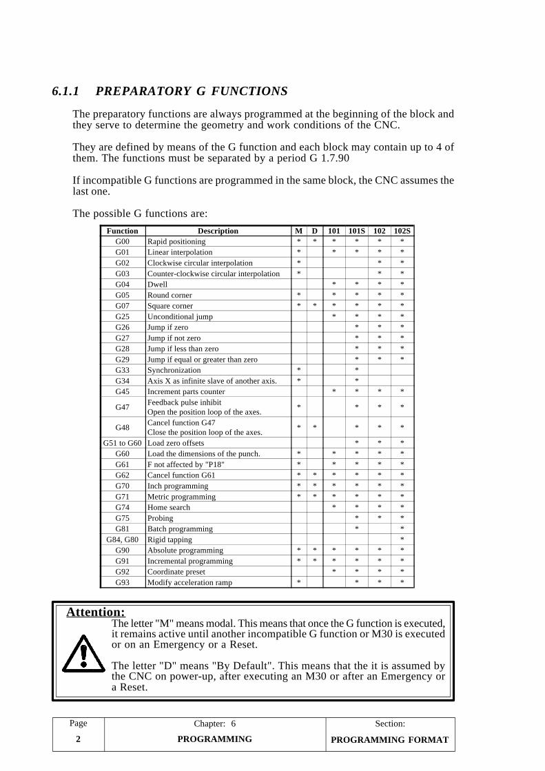
Section:Page
PROGRAMMING2
Chapter: 6
PROGRAMMING FORMAT
6.1.1 PREPARATORY G FUNCTIONS
The preparatory functions are always programmed at the beginning of the block andthey serve to determine the geometry and work conditions of the CNC.
They are defined by means of the G function and each block may contain up to 4 ofthem. The functions must be separated by a period G 1.7.90
If incompatible G functions are programmed in the same block, the CNC assumes thelast one.
The possible G functions are:
Attention:The letter "M" means modal. This means that once the G function is executed,it remains active until another incompatible G function or M30 is executedor on an Emergency or a Reset.
The letter "D" means "By Default". This means that the it is assumed bythe CNC on power-up, after executing an M30 or after an Emergency ora Reset.
Function Description M D 101 101S 102 102SG00 Rapid positioning * * * * * *G01 Linear interpolation * * * * *G02 Clockwise circular interpolation * * *G03 Counter-clockwise circular interpolation * * *G04 Dwell * * * *G05 Round corner * * * * *G07 Square corner * * * * * *G25 Unconditional jump * * * *G26 Jump if zero * * *G27 Jump if not zero * * *G28 Jump if less than zero * * *G29 Jump if equal or greater than zero * * *G33 Synchronization * *G34 Axis X as infinite slave of another axis. * *G45 Increment parts counter * * * *
G47 Feedback pulse inhibitOpen the position loop of the axes. * * * *
G48 Cancel function G47Close the position loop of the axes. * * * * *
G51 to G60 Load zero offsets * * *G60 Load the dimensions of the punch. * * * * *G61 F not affected by "P18" * * * * *G62 Cancel function G61 * * * * * *G70 Inch programming * * * * * *G71 Metric programming * * * * * *G74 Home search * * * *G75 Probing * * *G81 Batch programming * *
G84, G80 Rigid tapping *G90 Absolute programming * * * * * *G91 Incremental programming * * * * * *G92 Coordinate preset * * * *G93 Modify acceleration ramp * * * *
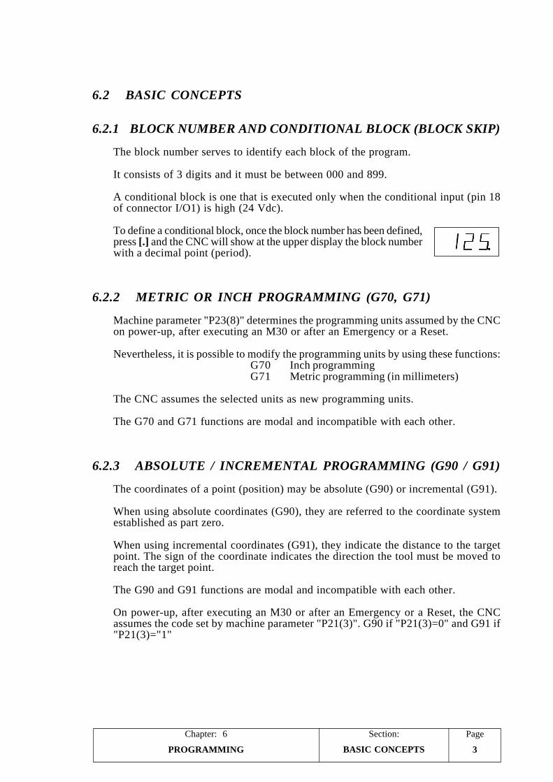
PageChapter: 6 Section:
PROGRAMMING 3BASIC CONCEPTS
6.2 BASIC CONCEPTS
6.2.1 BLOCK NUMBER AND CONDITIONAL BLOCK (BLOCK SKIP)
The block number serves to identify each block of the program.
It consists of 3 digits and it must be between 000 and 899.
A conditional block is one that is executed only when the conditional input (pin 18of connector I/O1) is high (24 Vdc).
To define a conditional block, once the block number has been defined,press [.] and the CNC will show at the upper display the block numberwith a decimal point (period).
6.2.2 METRIC OR INCH PROGRAMMING (G70, G71)
Machine parameter "P23(8)" determines the programming units assumed by the CNCon power-up, after executing an M30 or after an Emergency or a Reset.
Nevertheless, it is possible to modify the programming units by using these functions:G70 Inch programmingG71 Metric programming (in millimeters)
The CNC assumes the selected units as new programming units.
The G70 and G71 functions are modal and incompatible with each other.
6.2.3 ABSOLUTE / INCREMENTAL PROGRAMMING (G90 / G91)
The coordinates of a point (position) may be absolute (G90) or incremental (G91).
When using absolute coordinates (G90), they are referred to the coordinate systemestablished as part zero.
When using incremental coordinates (G91), they indicate the distance to the targetpoint. The sign of the coordinate indicates the direction the tool must be moved toreach the target point.
The G90 and G91 functions are modal and incompatible with each other.
On power-up, after executing an M30 or after an Emergency or a Reset, the CNCassumes the code set by machine parameter "P21(3)". G90 if "P21(3)=0" and G91 if"P21(3)="1"
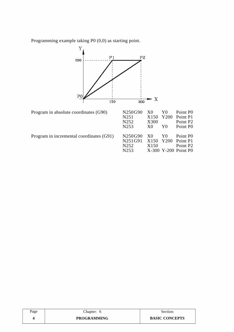
Section:Page
PROGRAMMING4
Chapter: 6
BASIC CONCEPTS
Programming example taking P0 (0,0) as starting point.
Program in absolute coordinates (G90) N250G90 X0 Y0 Point P0N251 X150 Y200 Point P1N252 X300 Point P2N253 X0 Y0 Point P0
Program in incremental coordinates (G91) N250G90 X0 Y0 Point P0N251G91 X150 Y200 Point P1N252 X150 Point P2N253 X-300 Y-200 Point P0
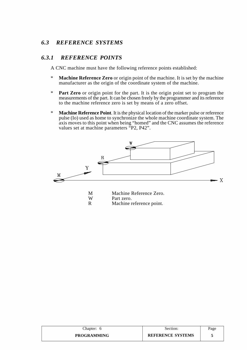
PageChapter: 6 Section:
PROGRAMMING 5REFERENCE SYSTEMS
6.3 REFERENCE SYSTEMS
6.3.1 REFERENCE POINTS
A CNC machine must have the following reference points established:
* Machine Reference Zero or origin point of the machine. It is set by the machinemanufacturer as the origin of the coordinate system of the machine.
* Part Zero or origin point for the part. It is the origin point set to program themeasurements of the part. It can be chosen freely by the programmer and its referenceto the machine reference zero is set by means of a zero offset.
* Machine Reference Point. It is the physical location of the marker pulse or referencepulse (Io) used as home to synchronize the whole machine coordinate system. Theaxis moves to this point when being “homed” and the CNC assumes the referencevalues set at machine parameters “P2, P42”.
M Machine Reference Zero.W Part zero.R Machine reference point.
Section:Page
PROGRAMMING6
Chapter: 6
REFERENCE SYSTEMS
6.3.2 MACHINE REFERENCE (HOME) SEARCH (G74)
The axes may be programmed to be homed separately or together.
Home search on one axis.
Program function G74 followed by the axis to be referenced: G74 X or G74 Y.
Home search on both axes
Program G74 alone in a block.
The CNC starts homing the axes in the order established by machine parameterP61(3).
If "P61(3)=0" First X and then YIf "P61(3)=1" First Y and then X
Attention:
A block containing function G74 may not contain any other G function.
When homing in JOG mode, the currently active zero offset (part zero)will be cancelled and the CNC will display the home coordinates set bymachine parameters "P2, P42".
In all other cases, the selected part zero will be maintained. Therefore,the coordinates being displayed will be referred to that part zero.
Function G74 implies function G01 which means that after executingG74 the CNC assumes function G01.
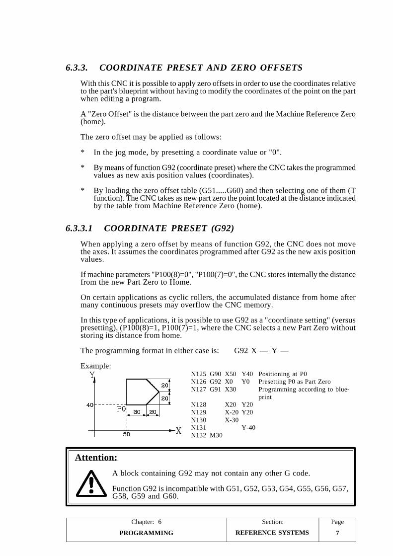
PageChapter: 6 Section:
PROGRAMMING 7REFERENCE SYSTEMS
6.3.3. COORDINATE PRESET AND ZERO OFFSETS
With this CNC it is possible to apply zero offsets in order to use the coordinates relativeto the part's blueprint without having to modify the coordinates of the point on the partwhen editing a program.
A "Zero Offset" is the distance between the part zero and the Machine Reference Zero(home).
The zero offset may be applied as follows:
* In the jog mode, by presetting a coordinate value or "0".
* By means of function G92 (coordinate preset) where the CNC takes the programmedvalues as new axis position values (coordinates).
* By loading the zero offset table (G51.....G60) and then selecting one of them (Tfunction). The CNC takes as new part zero the point located at the distance indicatedby the table from Machine Reference Zero (home).
6.3.3.1 COORDINATE PRESET (G92)
When applying a zero offset by means of function G92, the CNC does not movethe axes. It assumes the coordinates programmed after G92 as the new axis positionvalues.
If machine parameters "P100(8)=0", "P100(7)=0", the CNC stores internally the distancefrom the new Part Zero to Home.
On certain applications as cyclic rollers, the accumulated distance from home aftermany continuous presets may overflow the CNC memory.
In this type of applications, it is possible to use G92 as a "coordinate setting" (versuspresetting), (P100(8)=1, P100(7)=1, where the CNC selects a new Part Zero withoutstoring its distance from home.
The programming format in either case is: G92 X — Y —
Example:N125 G90 X50 Y40 Positioning at P0N126 G92 X0 Y0 Presetting P0 as Part ZeroN127 G91 X30 Programming according to blue-
printN128 X20 Y20N129 X-20 Y20N130 X-30N131 Y-40N132 M30
Attention:
A block containing G92 may not contain any other G code.
Function G92 is incompatible with G51, G52, G53, G54, G55, G56, G57,G58, G59 and G60.
Section:Page
PROGRAMMING8
Chapter: 6
REFERENCE SYSTEMS
6.3.3.2 ZERO OFFSET LOADING (G51.....G60)
In order to use these functions, the internal CNC table must be set as zero offset table,"P60(5)=1".
To see how to access this table, refer to the chapter on "AUX MODE" describedearlier in this manual.
Table address 1 corresponds to function G51, 2 to G52 and so on up to address 10which corresponds to G60.
Functions G51, G52, G53, G54, G55, G56, G57, G58, G59 and G60 must beprogrammed alone in the block and are incompatible with G92.
Their programming format is: G51 ... G60 X Y
The X and Y values indicate the distance from Machine Reference Zero (home)where the part zero is to be set.
When executing one of these functions: G51, G52, G53, G54, G55, G56, G57, G58,G59, G60, the CNC loads the new XY values at its corresponding table address.
6.3.3.3 ZERO OFFSET SELECTION (T1 ... T10)
To select a particular zero offset, use the "T" function.
The CNC cancels the previous zero offset and applies the new one.
The new part zero will be located at a distance from home set by the XY values ofthe corresponding table address.
Example. G52 X100 Y50 Loads the table with X100 Y50T2 Selects zero offset T2. The new part zero is at X100
Y50 from home.
This type of programmable zero offsets are very useful for repetitive operations to beperformed at different positions along the axes.
Attention:
"T0" cancels the previously active zero offset and does not apply a newone. Therefore, the new part zero will coincide with the Machine ReferenceZero (home).
PageChapter: 6 Section:
PROGRAMMING 9COMPLEMENTARYFUNCTIONS
6.4 COMPLEMENTARY FUNCTIONS
The CNC offers the following complementary functions.
F Feedrate for the axesS Spindle speed.T Tool number / Zero offsetM Miscellaneous (auxiliary) function
This programming order must be maintained within a block; but all of them need notbe programmed in the block.
6.4.1 AXIS FEEDRATE "F"
This function indicates the feedrate of the axes when operating in closed positioningloop.
When operating in servo-controlled open loop, the path is not controlled.
If "F" is programmed while in non-servo-controlled open loop, the CNC will issueerror 45.
With the "F" function ,it is possible to program the feedrate of the axes for G01, G02and G03 movements.
In rapid positioning, G00, the feedrates for the axes are set by machine parameters"P27" and "P67".
If "F" is not programmed or "F0" has been programmed, the CNC carries out theG01, G02 and G03 interpolations at the feedrates set by machine parameters "P27"and "P67".
It is possible to vary the feedrate of the axes by means of the external operator panel"JOG 100" or by using the Feedrate Override inputs, pins 10 and 11 of connectorI/O1.
6.4.2 SPINDLE SPEED "S"
With the "S" function, the spindle speed is programmed directly in revolutions perminute.
It accepts values between S0 and S9999, corresponding to 0 rpm. and 9999 rpm.
The actual maximum values are limited by machine parameters "P36", "P37", "P38"and "P39", depending, in each case, upon the selected spindle speed range.
Section:Page
PROGRAMMING10
Chapter: 6COMPLEMENTARY
FUNCTIONS
6.4.3 TOOL NUMBER "T"
In order to use this function, it is necessary to set the internal CNC table as a tool table,machine parameter "P60(5)=0".
To see how to access this table, refer to the chapter on "AUX MODE" describedearlier in this manual.
Every time a "T" function is executed, the CNC assumes the XY values indicated onthe table and applies the corresponding tool length compensation to each axis.
If "T0" is programmed, the CNC applies no compensation and it cancels any one thatmay be active at the time.
Also, if machine parameter "P61(5)=0", every time a "T" function is executed, pins20 through 27 of connector I/O1 show the BCD code of the selected tool and pin 4of connector I/O2 outputs a "T Strobe".
6.4.4 ZERO OFFSET "T"
In order to use this function, the internal CNC table must be set as a zero offset table,machine parameter "P60(5)=1".
Every time a "T" function is executed, the CNC cancels the zero offset currently activeand it applies the new one.
The new part zero will be located at a distance from home set by the XY values ofthe corresponding table address.
This type of programmable zero offsets are very useful for repetitive operations to beperformed at different positions along the axes.
6.4.5 MISCELLANEOUS (AUXILIARY) "M" FUNCTION
After the "M" code, indicate the number of the miscellaneous function to be executed.There are 100 different miscellaneous functions (M00 through M99).
Up to 4 M functions may be programmed in a block and they must be separated bya period (M03.18.27).
When the new spindle speed requires a range change, the CNC automatically executesthe corresponding M function: M41, M42, M43 or M44. Therefore, when a blockcontains an "S" code which implies a range change, only up to 3 more "M" functionsmay be programmed.
Functions M41, M42, M43 and M44 cannot be programmed by the machine operator.
The M functions are executed at the beginning of the block except M00, M01 andM30 which are the last ones to be executed in the block.
When more than one "M" function has been programmed in a block, the CNC executesthem in the order they are programmed.
PageChapter: 6 Section:
PROGRAMMING 11COMPLEMENTARYFUNCTIONS
The CNC always outputs the "M" function via pins 20 through 27 of connector I/O1.These outputs may be either binary coded or BCD coded as described in the sectionon "Auxiliary M function" of the chapter on "Concepts" in the Installation Manual.
The following "M" functions have a specific internal meaning at the CNC.
M00. Program stop
When the CNC executes the M00 code, it interrupts the program. To resume it,press
M01. Conditional program stop
Same as M00 except that it is ignored unless the "Conditional Input" is active(high -> 24Vdc), pin 18 of connector I/O1.
M30. End of program with return to first program block
This code indicates the end of the program and performs a "General Reset" of theCNC setting it to initial conditions. It also stops the spindle (M05).
Plus, the CNC returns to the first block of the program in such way that ifis pressed again, the CNC will execute the program again from the beginning.
The M30 must always be programmed at the end of each program. Otherwise, theCNC will keep on executing all the following blocks.
If machine parameter "P21(4)=1", the CNC increments the count of the parts counterin one unit every time function M30 is executed.
M03. Clockwise spindle rotation
This code starts the spindle clockwise.
M04. Counter-clockwise spindle rotation
This code starts the spindle counter-clockwise.
M05. Spindle stop
This code stops the spindle.
M41,M42,M43,M44. Spindle speed range selection
The CNC offers 4 spindle speed ranges (gears) M41, M42, M43 and M44, withtheir maximum speed limits set by machine parameters "P36", "P37", "P38" and"P39".
When the new "S" value involves a range change, the CNC automatically outputsits corresponding M function (M41 through M44).
These codes cannot be programmed by the machine operator.
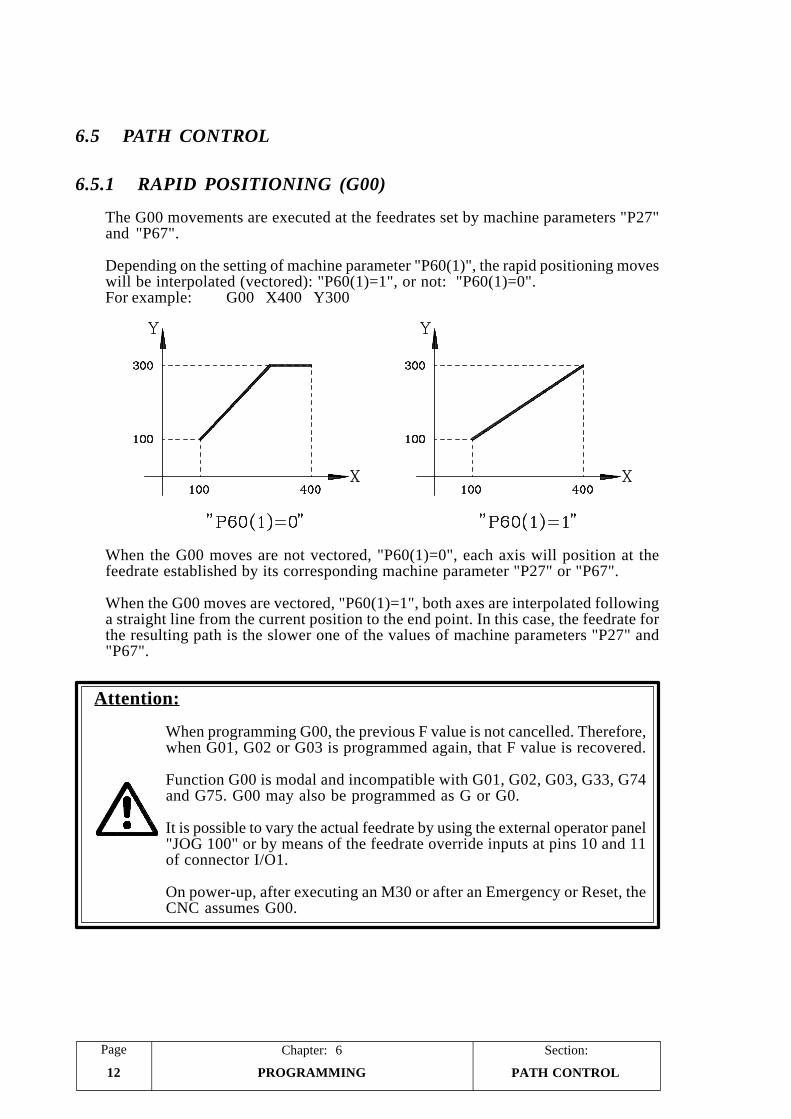
Section:Page
PROGRAMMING12
Chapter: 6
PATH CONTROL
6.5 PATH CONTROL
6.5.1 RAPID POSITIONING (G00)
The G00 movements are executed at the feedrates set by machine parameters "P27"and "P67".
Depending on the setting of machine parameter "P60(1)", the rapid positioning moveswill be interpolated (vectored): "P60(1)=1", or not: "P60(1)=0".For example: G00 X400 Y300
When the G00 moves are not vectored, "P60(1)=0", each axis will position at thefeedrate established by its corresponding machine parameter "P27" or "P67".
When the G00 moves are vectored, "P60(1)=1", both axes are interpolated followinga straight line from the current position to the end point. In this case, the feedrate forthe resulting path is the slower one of the values of machine parameters "P27" and"P67".
Attention:
When programming G00, the previous F value is not cancelled. Therefore,when G01, G02 or G03 is programmed again, that F value is recovered.
Function G00 is modal and incompatible with G01, G02, G03, G33, G74and G75. G00 may also be programmed as G or G0.
It is possible to vary the actual feedrate by using the external operator panel"JOG 100" or by means of the feedrate override inputs at pins 10 and 11of connector I/O1.
On power-up, after executing an M30 or after an Emergency or Reset, theCNC assumes G00.
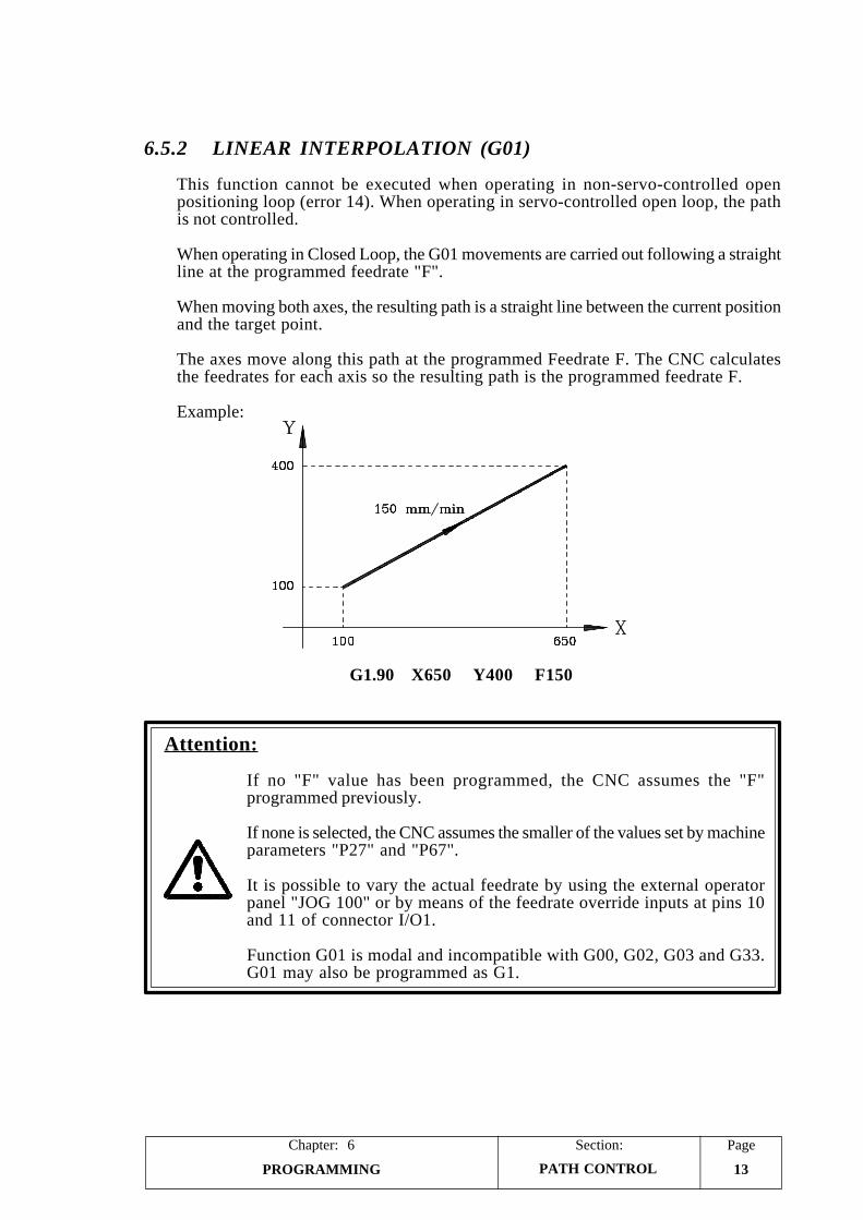
PageChapter: 6 Section:
PROGRAMMING 13PATH CONTROL
6.5.2 LINEAR INTERPOLATION (G01)
This function cannot be executed when operating in non-servo-controlled openpositioning loop (error 14). When operating in servo-controlled open loop, the pathis not controlled.
When operating in Closed Loop, the G01 movements are carried out following a straightline at the programmed feedrate "F".
When moving both axes, the resulting path is a straight line between the current positionand the target point.
The axes move along this path at the programmed Feedrate F. The CNC calculatesthe feedrates for each axis so the resulting path is the programmed feedrate F.
Example:
G1.90 X650 Y400 F150
Attention:
If no "F" value has been programmed, the CNC assumes the "F"programmed previously.
If none is selected, the CNC assumes the smaller of the values set by machineparameters "P27" and "P67".
It is possible to vary the actual feedrate by using the external operatorpanel "JOG 100" or by means of the feedrate override inputs at pins 10and 11 of connector I/O1.
Function G01 is modal and incompatible with G00, G02, G03 and G33.G01 may also be programmed as G1.
Section:Page
PROGRAMMING14
Chapter: 6
PATH CONTROL
6.5.3 CIRCULAR INTERPOLATION (G02, G03)
In order to perform a circular interpolation, the system must operate in Closed PositioningLoop.
There are two types of circular interpolations.
G02: Clockwise interpolation.G03: Counter-clockwise interpolation.
The movements programmed after G02 and G03, are carried out following a circularpath at the programmed feedrate F.
The programming format is: "G02 X Y I J" or "G03 X Y I J", where:
G02 Clockwise interpolation.G03 Counter-clockwise interpolation.X X coordinate of the end point.Y Y coordinate of the end point.I Distance from the arc's starting point to the center of the arc along X.J Distance from the arc's starting point to the center of the arc along Y.
The X and Y coordinates may be either absolute or incremental and the I and J valuesalways define the distance from the starting point to the center of the arc.
When any of the X or Y coordinates of the end point is the same as that of the startingpoint, it is not necessary to program it. However, the I and J values must always beprogrammed even when their values are "0".
Attention:
G02 and G03 are modal and incompatible with each other and with G00and G01.
G02/G03 may also be programmed as G2/G3.
It is possible to vary the actual feedrate by using the external operatorpanel "JOG 100" or by means of the feedrate override inputs at pins 10and 11 of connector I/O1.
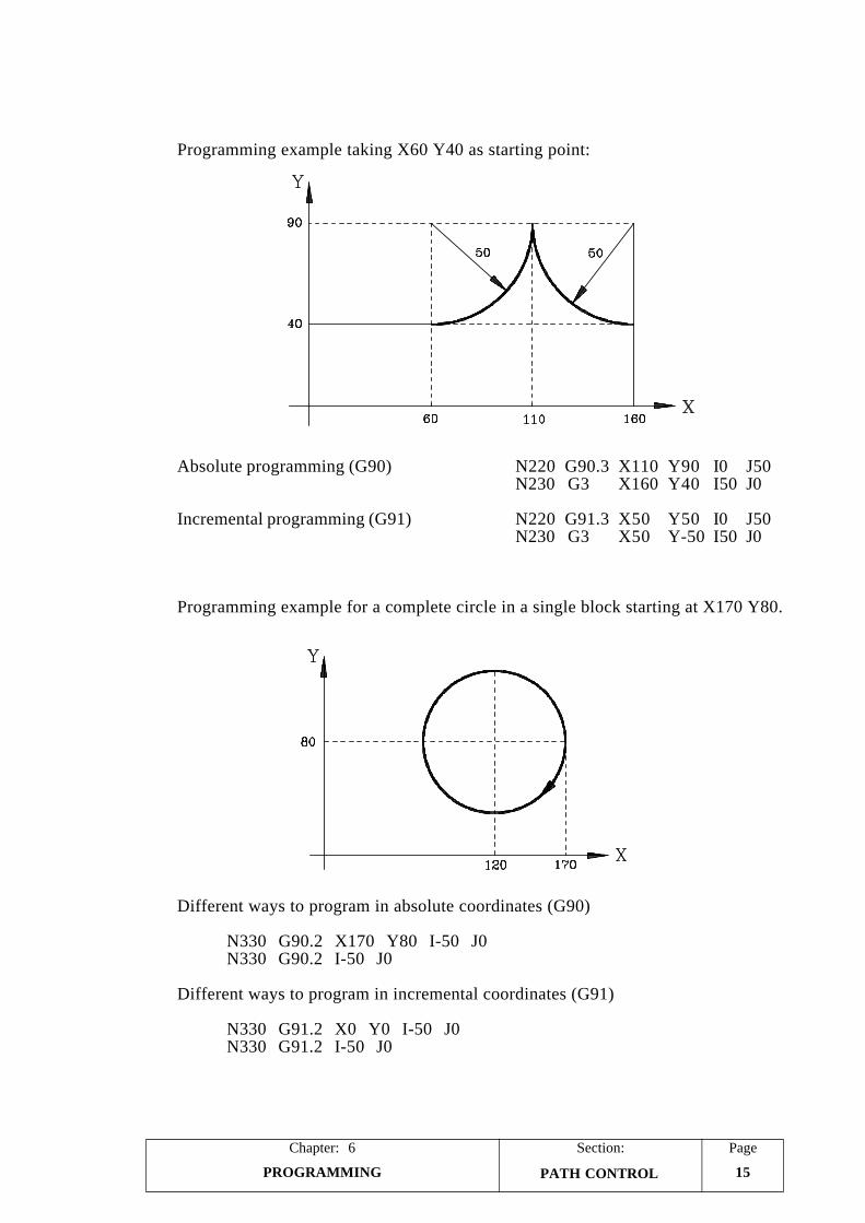
PageChapter: 6 Section:
PROGRAMMING 15PATH CONTROL
Programming example taking X60 Y40 as starting point:
Absolute programming (G90) N220 G90.3 X110 Y90 I0 J50N230 G3 X160 Y40 I50 J0
Incremental programming (G91) N220 G91.3 X50 Y50 I0 J50N230 G3 X50 Y-50 I50 J0
Programming example for a complete circle in a single block starting at X170 Y80.
Different ways to program in absolute coordinates (G90)
N330 G90.2 X170 Y80 I-50 J0N330 G90.2 I-50 J0
Different ways to program in incremental coordinates (G91)
N330 G91.2 X0 Y0 I-50 J0N330 G91.2 I-50 J0
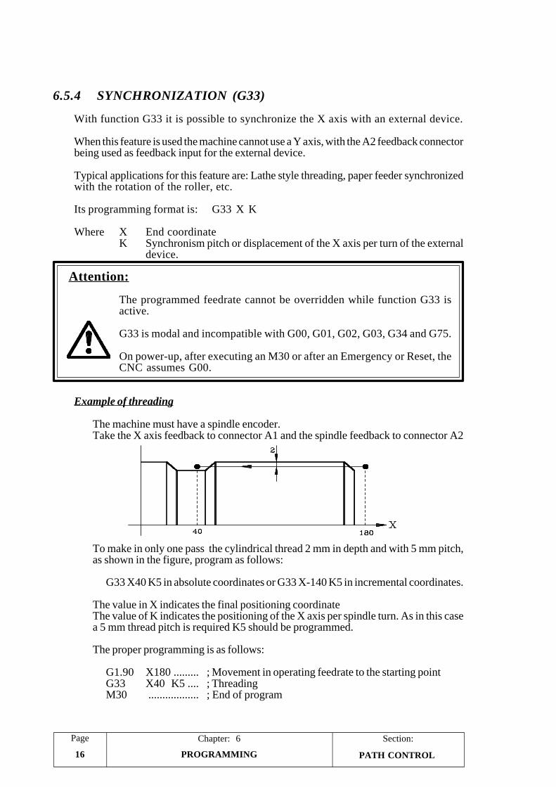
Section:Page
PROGRAMMING16
Chapter: 6
PATH CONTROL
6.5.4 SYNCHRONIZATION (G33)
With function G33 it is possible to synchronize the X axis with an external device.
When this feature is used the machine cannot use a Y axis, with the A2 feedback connectorbeing used as feedback input for the external device.
Typical applications for this feature are: Lathe style threading, paper feeder synchronizedwith the rotation of the roller, etc.
Its programming format is: G33 X K
Where X End coordinateK Synchronism pitch or displacement of the X axis per turn of the external
device.
Attention:
The programmed feedrate cannot be overridden while function G33 isactive.
G33 is modal and incompatible with G00, G01, G02, G03, G34 and G75.
On power-up, after executing an M30 or after an Emergency or Reset, theCNC assumes G00.
Example of threading
The machine must have a spindle encoder.Take the X axis feedback to connector A1 and the spindle feedback to connector A2
To make in only one pass the cylindrical thread 2 mm in depth and with 5 mm pitch,as shown in the figure, program as follows:
G33 X40 K5 in absolute coordinates or G33 X-140 K5 in incremental coordinates.
The value in X indicates the final positioning coordinateThe value of K indicates the positioning of the X axis per spindle turn. As in this casea 5 mm thread pitch is required K5 should be programmed.
The proper programming is as follows:
G1.90 X180 ......... ; Movement in operating feedrate to the starting pointG33 X40 K5 .... ; ThreadingM30 .................. ; End of program
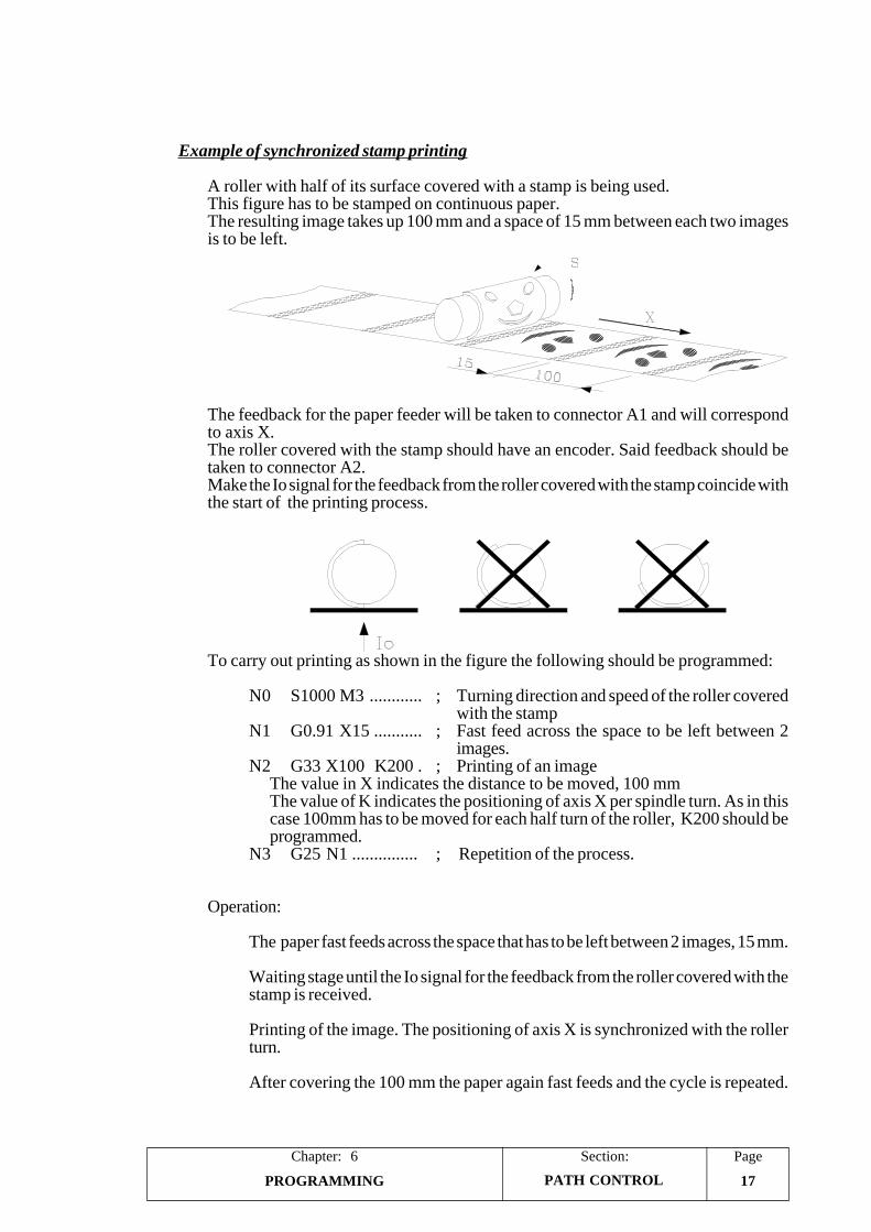
PageChapter: 6 Section:
PROGRAMMING 17
Example of synchronized stamp printing
A roller with half of its surface covered with a stamp is being used.This figure has to be stamped on continuous paper.The resulting image takes up 100 mm and a space of 15 mm between each two imagesis to be left.
The feedback for the paper feeder will be taken to connector A1 and will correspondto axis X.The roller covered with the stamp should have an encoder. Said feedback should betaken to connector A2.Make the Io signal for the feedback from the roller covered with the stamp coincide withthe start of the printing process.
To carry out printing as shown in the figure the following should be programmed:
N0 S1000 M3 ............ ; Turning direction and speed of the roller coveredwith the stamp
N1 G0.91 X15 ........... ; Fast feed across the space to be left between 2images.
N2 G33 X100 K200 . ; Printing of an imageThe value in X indicates the distance to be moved, 100 mmThe value of K indicates the positioning of axis X per spindle turn. As in thiscase 100mm has to be moved for each half turn of the roller, K200 should beprogrammed.
N3 G25 N1 ............... ; Repetition of the process.
Operation:
The paper fast feeds across the space that has to be left between 2 images, 15 mm.
Waiting stage until the Io signal for the feedback from the roller covered with thestamp is received.
Printing of the image. The positioning of axis X is synchronized with the rollerturn.
After covering the 100 mm the paper again fast feeds and the cycle is repeated.
PATH CONTROL
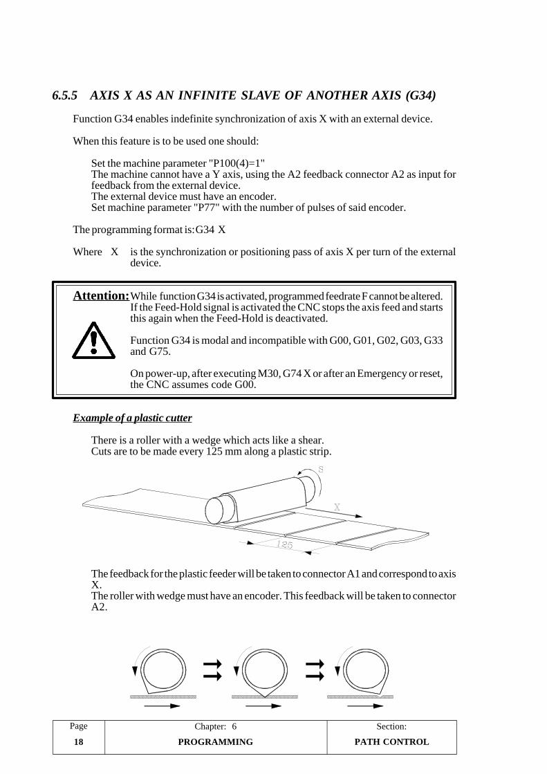
Section:Page
PROGRAMMING18
Chapter: 6
6.5.5 AXIS X AS AN INFINITE SLAVE OF ANOTHER AXIS (G34)
Function G34 enables indefinite synchronization of axis X with an external device.
When this feature is to be used one should:
Set the machine parameter "P100(4)=1"The machine cannot have a Y axis, using the A2 feedback connector A2 as input forfeedback from the external device.The external device must have an encoder.Set machine parameter "P77" with the number of pulses of said encoder.
The programming format is:G34 X
Where X is the synchronization or positioning pass of axis X per turn of the externaldevice.
Attention:While function G34 is activated, programmed feedrate F cannot be altered.If the Feed-Hold signal is activated the CNC stops the axis feed and startsthis again when the Feed-Hold is deactivated.
Function G34 is modal and incompatible with G00, G01, G02, G03, G33and G75.
On power-up, after executing M30, G74 X or after an Emergency or reset,the CNC assumes code G00.
Example of a plastic cutter
There is a roller with a wedge which acts like a shear.Cuts are to be made every 125 mm along a plastic strip.
The feedback for the plastic feeder will be taken to connector A1 and correspond to axisX.The roller with wedge must have an encoder. This feedback will be taken to connectorA2.
PATH CONTROL
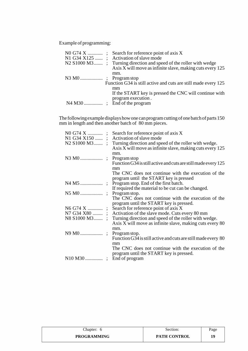
PageChapter: 6 Section:
PROGRAMMING 19
Example of programming:
N0 G74 X ............ ; Search for reference point of axis XN1 G34 X125 ...... ; Activation of slave modeN2 S1000 M3....... ; Turning direction and speed of the roller with wedge
Axis X will move as infinite slave, making cuts every 125mm.
N3 M0 .................. ; Program stop Function G34 is still active and cuts are still made every 125
mmIf the START key is pressed the CNC will continue withprogram execution .
N4 M30 ............... ; End of the program
The following example displays how one can program cutting of one batch of parts 150mm in length and then another batch of 80 mm pieces.
N0 G74 X ............ ; Search for reference point of axis XN1 G34 X150 ...... ; Activation of slave modeN2 S1000 M3....... ; Turning direction and speed of the roller with wedge.
Axis X will move as infinite slave, making cuts every 125mm.
N3 M0 .................. ; Program stopFunction G34 is still active and cuts are still made every 125mmThe CNC does not continue with the execution of theprogram until the START key is pressed
N4 M5 .................. ; Program stop. End of the first batch.If required the material to be cut can be changed.
N5 M0 .................. ; Program stop.The CNC does not continue with the execution of theprogram until the START key is pressed.
N6 G74 X ............ ; Search for reference point of axis XN7 G34 X80 ........ ; Activation of the slave mode. Cuts every 80 mmN8 S1000 M3....... ; Turning direction and speed of the roller with wedge.
Axis X will move as infinite slave, making cuts every 80mm.
N9 M0 .................. ; Program stop.Function G34 is still active and cuts are still made every 80mmThe CNC does not continue with the execution of theprogram until the START key is pressed.
N10 M30 .............. ; End of program
PATH CONTROL
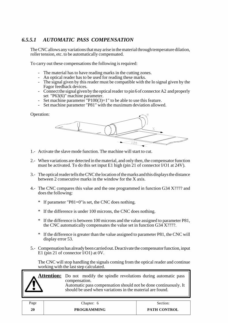
Section:Page
PROGRAMMING20
Chapter: 6
6.5.5.1 AUTOMATIC PASS COMPENSATION
The CNC allows any variations that may arise in the material through temperature dilation,roller tension, etc. to be automatically compensated.
To carry out these compensations the following is required:
- The material has to have reading marks in the cutting zones.- An optical reader has to be used for reading these marks.- The signal given by this reader must be compatible with the Io signal given by the
Fagor feedback devices.- Connect the signal given by the optical reader to pin 6 of connector A2 and properly
set "P63(6)" machine parameter.- Set machine parameter "P100(3)=1" to be able to use this feature.- Set machine parameter "P81" with the maximum deviation allowed.
Operation:
1.- Activate the slave mode function. The machine will start to cut.
2.- When variations are detected in the material, and only then, the compensator functionmust be activated. To do this set input E1 high (pin 21 of connector I/O1 at 24V).
3.- The optical reader tells the CNC the location of the marks and this displays the distancebetween 2 consecutive marks in the window for the X axis.
4.- The CNC compares this value and the one programmed in function G34 X???? anddoes the following:
* If parameter "P81=0"is set, the CNC does nothing.
* If the difference is under 100 microns, the CNC does nothing.
* If the difference is between 100 microns and the value assigned to parameter P81,the CNC automatically compensates the value set in function G34 X????.
* If the difference is greater than the value assigned to parameter P81, the CNC willdisplay error 53.
5.- Compensation has already been carried out. Deactivate the compensator function, inputE1 (pin 21 of connector I/O1) at 0V.
The CNC will stop handling the signals coming from the optical reader and continueworking with the last step calculated.
Attention: Do not modify the spindle revolutions during automatic passcompensation.Automatic pass compensation should not be done continuously. Itshould be used when variations in the material are found.
PATH CONTROL
PageChapter: 6 Section:
PROGRAMMING 21ADDITIONAL PREPARATORYFUNCTIONS
6.6 ADDITIONAL PREPARATORY FUNCTIONS
6.6.1 DWELL (G04)
A dwell (delay) may be programmed by using function G04.
To do this, after the G04 code, press the decimal point and indicate the desired dwellin seconds. The maximum dwell programmable in a block is 99.99 seconds.
Examples:
G04.99.99 99.99 second dwellG04.2 2 second dwell.G04.0.01 0.01 second dwell.
Attention:
G04 may also be programmed as G4.
The dwell is always executed at the beginning of the block containing it.
The block containing function G04 cannot have any more G codes; but itmay have other functions (X, Y, F, S, T, etc)
6.6.2 INCREMENT PART COUNTER (G45)
The CNC has an internal part counter which increments its count in one unit in thefollowing cases:
* Every time G45 is executed.
* Every time M30 is executed if machine parameter "P21(4)=1".
Its maximum count value is 9999 and it rolls over starting at 0, 1, 2, and so forth.
To see the value of this counter or reset it to "0", proceed as described in the sectionon "Display Modes" of the chapter on "Program Execution" in this manual.
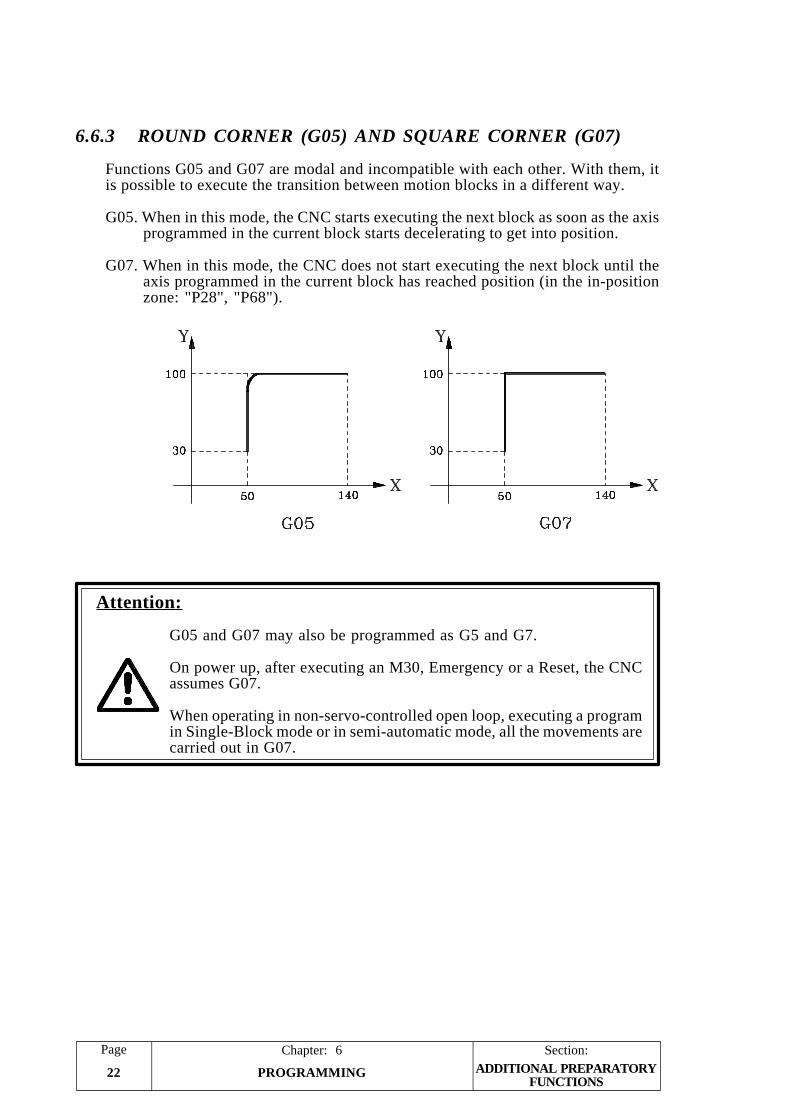
Section:Page
PROGRAMMING22
Chapter: 6ADDITIONAL PREPARATORY
FUNCTIONS
6.6.3 ROUND CORNER (G05) AND SQUARE CORNER (G07)
Functions G05 and G07 are modal and incompatible with each other. With them, itis possible to execute the transition between motion blocks in a different way.
G05. When in this mode, the CNC starts executing the next block as soon as the axisprogrammed in the current block starts decelerating to get into position.
G07. When in this mode, the CNC does not start executing the next block until theaxis programmed in the current block has reached position (in the in-positionzone: "P28", "P68").
Attention:
G05 and G07 may also be programmed as G5 and G7.
On power up, after executing an M30, Emergency or a Reset, the CNCassumes G07.
When operating in non-servo-controlled open loop, executing a programin Single-Block mode or in semi-automatic mode, all the movements arecarried out in G07.
PageChapter: 6 Section:
PROGRAMMING 23SPECIAL FUNCTIONS
6.7 SPECIAL FUNCTIONS
6.7.1 FEEDBACK INHIBIT (G47, G48)
In some applications, after positioning the part, sheetmetal, etc. it is necessary to correctits position.
This correction is made by an external device not controlled by the CNC.
When executing function G47, the CNC ignores the possible movements caused bythat device, thus inhibiting the feedback pulses.
The programming formats for this function are:
G47 X It ignores the X axis feedback pulses.
G47 Y It ignores the Y axis feedback pulses.
G47 It ignores the feedback pulses from both axes.
To cancel this feature and return to normal feedback monitoring, program functionG48.
Attention:
G47 is modal.
When G47 is active, the CNC ignores the feedback pulses once the axisis in position.
If a movement block is executed afterwards (G00, G01, G02, G03,...) theCNC switches to control the feedback thus preventing the machine frommoving out of control.
Once the programmed movement has ended (reaching position), the CNCswitches back to ignoring the feedback pulses.
If while G47 is active, one or both axes are moved and, then, G48 isprogrammed, the CNC does not recover the lost position.
On power-up, after executing an M30, after an Emergency or a Reset, theCNC assumes G48.
Section:Page
PROGRAMMING24
Chapter: 6
6.7.2 G47, G48 AS OPENING OF THE AXIS LOOP
In particular applications such as presses, metal forming machines, sheetmetal formingmachines, etc., the part undergoes a movement or pull while it is machined.
By means of functions G47, G48 the CNC allows the loop of the axis undergoing the pullto be opened or closed.
When the position loop is closed, in normal operating mode, the CNC controls the axisfeedrate at all times.
When the position loop is opened the axis operates in DRO mode, that is, the CNC doesnot control the feedrate of the axes but does take into account their movements.
Example of sheetmetal forming machines:Normal operation is with the position loop closed.When the tube forming is to be done the following steps must be taken:- Open the position loop of the axis undergoing the pull and the axis starts to operate
in DRO mode.- Form the tube. The CNC displays at all times the position coordinate of both axes,
that is, it accurately reflects the tugs undergone by the tube.After forming the tube close the axis position loop again.
In order to be able to use functions G47, G48 as opening for the axis loop machine parameter"P101(3)=1" has to be set.
The programming formats of this function are:
G47 X Opens the position loop of axis X.
G47 Y Opens the position loop of axis Y.
G47 Opens the position loop of both axes
G48 X Closes the position loop of axis X.
G48 Y Closes the position loop of axis Y.
G48 Closes the position loop of both axes.
Attention:Functions G47 and G48 are modal.
The block containing function G47 or G48 cannot contain other functions(X, Y, F, S, T, etc.)
If a movement block of an axis operating in open position loop is executed,the CNC will display the corresponding error code.
On power-up, after executing an M30 or after an Emergency or Reset, theCNC assumes function G48.
SPECIAL FUNCTIONS
PageChapter: 6 Section:
PROGRAMMING 25
6.7.3 THE FEEDRATE F IS NOT AFFECTED BY "P18" (G61, G62)
When operating with feedrates slower than 1 mm/min. or 1 inch/min. machine parameter"P18" must be set to a value other than "0".
The CNC divides the programmed feedrate by the P18 value and applies the result asaxis feedrate.
It is possible to program whether this "P18" is to be considered or ignored by meansof functions G61 and G62.
G61 The value of P18 is ignored. The CNC applies the programmed F value.G62 The value of P18 is not ignored. The programmed feedrate F value is affected
by this value as described above.
Example: Machine parameter "P18 = 100"
N0 F1 Programmed F 1 mm/min.N1 G62.1 X20 Movement at 0.01 mm/min.N2 X-100 Movement at 0.01 mm/min.N3 G61 F not affected by P18N4 X0 Movement at 1 mm/min.N5 G62 F affected by P18N6 X30 Movement at 0.01 mm/min.N7 M30
Attention:
G61 and G62 are modal and incompatible with each other.
On power-up, after executing an M30, after an Emergency or a Reset, theCNC assumes G62.
6.7.4 ACCELERATION RAMP MODIFICATION (G93)
When the axes operate in Closed Loop, machine parameters "P16, P17", "P91" and"P92" set the acceleration and deceleration times for each axis.
In certain situations it may be interesting to apply other acc./dec. times.
With this function, it is possible to program the desired acc./dec. time.
Its programming format is: G93 X Y
Parameters X Y indicate in seconds, with millisecond accuracy, the acceleration timerequired for setting for each one of the axes. Maximum value 6 seconds.
Example: G93 X1.500 Y0.700 fixes an acceleration and deceleration ramp of 1.5 secondsfor axis X and another one of 700 milliseconds for axis Y.
On power-up, after executing an M30, after an Emergency or a Reset, the CNC assumesthe settings of machine parameters "P16, P17", "P91" and "P92".
SPECIAL FUNCTIONS
Section:Page
PROGRAMMING26
Chapter: 6
6.8 OTHERS FUNCTIONS
6.8.1 BATCH PROGRAMMING (G81)
This function is especially designed for feeders of sheetmetal, cardboard, paper, plastic,etc.
It allows programming batches of parts having the same length.
Its programming format is: G81 L C A
L Length of each part of the batch.C Number of parts to make.A Forewarning part number
Example: To make a batch of 100 parts, each being 200mm long and warningwhen there are 3 parts left to finish the batch: G81 L200 C100 A2
Function G81 executes a G92 after each part (after each feed), thus being necessaryto set "P100(8)=1" so the G92 does not accumulate count (coordinate setting)
Basic operation:
1.- When pressing or receiving the external Cycle Start command.
2.- The CNC executes function G92 X0 setting the X axis coordinate to "0".
3.- The X axis moves the distance indicated by parameter "L" in G01 and theprogrammed feedrate F. It assumes the G05 or G07 previously active.
4.- Once the axis is in position, the CNC outputs an "M07" for the machine to cut thematerial. The part counter is incremented and the cycle is interrupted.
5.- The CNC verifies the following:
a) If the whole lot has been cut, number of parts equal to "C", the CNC outputsan "M09" and concludes the execution of function "G81".
b) When there are "A" parts left to go, the CNC outputs function "M08" so theforewarning signal is activated.
6.- If all the parts have not been made yet, the CNC waits for another Cycle Startcommand in order to resume the execution of the cycle from step "2".
Attention:
G81 is not modal. Therefore, it must be programmed every time.
It uses the internal CNC part counter. It resets it to zero at the beginningof the execution and it increments it every time it executes a part.
In the counter display mode, the CNC shows, on the left-hand side, thenumber of parts programmed for the batch and, on the right-hand side, thenumber of parts already made.
OTHER FUNCTIONS
PageChapter: 6 Section:
PROGRAMMING 27
Once the cycle has been defined, the CNC stores the definition parametervalues, thus not being necessary to redefine them.
N00 G81 L255 C200 A10 F1000N01 G81 L387.5 C350 Takes A10N02 G81 Takes L387.5 C350 A10N03 M30
The definition parameters "L", "C" and "A" are associated to arithmeticparameters "P0", "P1" and "P2" respectively.
Therefore, function "G81" may be defined by using the definition parameters"L", "C" and "A" and/or the arithmetic parameters "P0", "P1" and "P2", asillustrated by the following example:
N000 G81 L255 C200 A10 N000 P0=255N001 P1=200N002 P2=10N003 G81
N002 G81 L387 C350 N004 P0=387N005 P1=350N006 G81
N004 G81 L104.5 C80 A8 N007 P0=104.5N008 P1=80N009 G81 A8
N006 M30 N010 M30
If the external START signal is activated automatically after each cut, the CNC willstart executing the following block after the last cut.
Example N00 G81 L25500 C200 A10 F1000N01 G81 L38700 C350 A20N02 M0 Interrupts the program.N03 G81 L10450 C80 A8N04 M30
OTHER FUNCTIONS
Section:Page
PROGRAMMING28
Chapter: 6
6.8.2 PROBING (G75)
With function G75, it is possible to make movements ending when the CNC receivesthe signal from a touch probe.
The definition format is: G75 X Y
After G75, the desired axes must be programmed followed by the coordinates of thetarget point.
The axes will move in G01 and at the programmed feedrate F until the external signalfrom the touch probe is received. At that point, the CNC will conclude the blockassuming as theoretical position of the axes their real position at the time.
If the axes reach their target position before the CNC receives the probe signal, theCNC stops the axes and issues error 21.
Attention:
G75 is not modal. Therefore, it must be programmed every time. It alsoimplies function G01 which means that after a G75 block, the CNC assumesfunction G01.
The programmed feedrate cannot be overridden during the probing move.
Once G75 is executed, it is possible to assign the position of each axis toany arithmetic parameter and, by using arithmetic programming, generatespecial programs for measurement and calibration of tools and parts.
OTHER FUNCTIONS

PageChapter: 6 Section:
PROGRAMMING 29
6.8.3 RIGID TAPPING (G84, G80)
With function G84, it is possible to tap a part by interpolating the spindle rotation withthe movement of the axis.
The machine must have an X axis and a servo-controlled spindle (with servo-driveand spindle encoder).
The spindle feedback is connected to input A2 and the analog output for the spindleis provided at pins 34 and 35 of connector I/O1.
When the machine has a rigid tapping axis Y cannot be used. If you wish to use an electronichandwheel this must be connected to pins 17 and 25 of connector I/O2
Nevertheless, the CNC uses the Y function to define the thread pitch. Consequently,machine parameter "P60(8)" must be set to "0" to enable this function
P63(3)=1 The machine uses rigid tapping.P60(8)=0 Enable the Y function.P77 Number of spindle encoder pulses.
Its programming format is: G84 X Y F S
X Defines the depth of the tap.
Y Defines the tapping pitch.
When assigning a positive value, it must be defined in turns/mm or turns/inch. and when assigning a negative value, in mm/turn or inches/turn.
F Defines the tap-in speed in rpm.
S Defines the tap-out speed in rpm.
If parameter "F" is programmed and not the "S" parameter, the tap-in and tap-outmovements are performed at the same speed, the one indicated by parameter "F".
If parameters "F" and "S" are not programmed, the CNC assumes the values usedon the previous tap. If no tapping operation was performed previously, the CNCwill issue the corresponding error.
Parameters "F" and "S" are reset to "0" on power-up, after an Emergency or aReset.
OTHER FUNCTIONS
Section:Page
PROGRAMMING30
Chapter: 6
General Considerations
* When the machine uses rigid tapping "P63(3)=1" the spindle control is done inclosed loop.
* To switch it to open loop, G80 must be executed.
From this point on, the spindle control is done in open loop and it is possible toprogram the "S" function.
Function G80 must be programmed alone in the block.
* The spindle will operate in closed loop again, if G84 is programmed, on power-up, after executing an M30 or after an Emergency or Reset.
* The spindle turning direction during rigid tapping must be defined before functionG84 and by means of M3, M4.
If when executing G84, no turning direction has been selected, the CNC assumesthe M03 (clockwise).
* All the various movements involved in rigid tapping are treated as a single block.In other words, when executing a G84 cycle in the Single-Block, the CNC makesthe whole tap.
* When executing function G84, the CNC assumes functions G01 and G07.
* If due to possible spindle backlash, an additional spindle rotation is required at thebottom of the tap, it must be indicated by arithmetic parameter P19 in the numberof spindle encoder pulses to move.
The CNC recovers this additional movement by rotating in the opposite directionat the end of the tap.
* A dwell at the bottom of the tap is also possible by indicating it, in milliseconds,with machine parameter "P32".
OTHER FUNCTIONS
PageChapter: 6 Section:
PROGRAMMING 31
Example and way to operate
A hole is to be tapped 20 mm deep with a thread pitch of 0.5 mm at a tap-in speedof 300 rpm and tap-out speed of 600 rpm.
The spindle encoder has 1000 lines and its pulses require a x4 multiplying factor.
Also, due to spindle backlash, it must turn 20 pulse units at the bottom of the tap.
It also requires a 100 millisecond dwell at the bottom of the tap.
The following CNC machine parameters must be set accordingly:
P63(3)=1 The machine uses rigid tapping.P60(8)=0 Enable the Y functionP77=1000 Spindle encoder line count (number of pulses)P61(6)=0 Feedback multiplying factor for Y (S)P32=100 100 millisecond dwell at the bottom of the tap.
The tapping program looks like this:
N000 M3 Start the spindle clockwise.N010 P19 K20 Additional spindle movement at the bottom
of the tap.N020 G84 X20 Y0.5 F300 S600 Definition of the canned cycle.N030 M30 End of program.
The CNC carries out the following machining steps:
1.- Tap-in movement with the spindle turning at 300 rpm.
The X axis moves to X 20.000The Y (S) axis moves toY 40.000 (20000 x 0.5 x 1000 x4)
2.- Once at the bottom of the tap, the spindle moves the amount indicated byarithmetic parameter P19, 20 pulses.
The Y (S) moves to Y 40.020
3.- 100 millisecond dwell as indicated by machine parameter P32.
4.- Tap-out move to clear the tap with the spindle turning at 600 rpm.
The X axis moves 20mm up to X 00.000The Y (S) axis moves (20000 x 0.5 x 1000 x4) up to Y 00.020
5.- Recovery of the additional move made at the bottom of the tap
The Y (S) axis moves up to Y 00.000
6.- End of tap and end of program.
OTHER FUNCTIONS
Section:Page
PROGRAMMING32
Chapter: 6
6.8.4 LOADING THE PUNCH SIZES (G60)
Function G60 can be used in two different ways.
For loading zero offsets
This is explained in section 6.3.3.2 of this same manual.
For loading the punch dimensions
This is particularly meant for punching machines. Machine parameter "P101(7)=1"must be set.
The CNC takes into account the dimensions of the punch during program execution,preventing its extremes from exceeding the travel limits fixed by machine parameter.
The programming format is G60 X Y. Values X and Y indicate half of the punchdimensions according to axes X and Y.
When the punch is round values X and Y coincide with the punch radius.
Attention:
On power-up, after executing M30 or after an Emergency or Reset, theCNC assigns value 0 to both dimensions of the punch.
OTHER FUNCTIONS
PageChapter: 6 Section:
PROGRAMMING 33PARAMETRICPROGRAMMING
6.9 PARAMETRIC PROGRAMMING
A parameter takes the place of a numeric value in the various functions of the program.
The programmer may use these parameters when editing his/her own programs. Lateron, and during execution, the CNC will replace these parameters with the values allocatedto them at the time.
Up to 100 (P0 through P99) arithmetic parameters may be used.
While editing a program, proceed as follows in order to assign an arithmetic parameterto a particular function (G, X, Y, F, S, etc):
* Select the desired function (G, X, Y, F, S, etc).* Press [P]. The CNC shows the letter "P" next to the selected function. For example:
"XP".* Key in the number of the arithmetic parameter.
Attention:
When defining, in the same block, several functions of the same type, allof them must be programmed with or without parametric format. The twoformats cannot be combined.
For example, block MP17.5.0 is the same as MP17 MP5 MP0 and not thesame as MP17 M5 M0.
When defining function "G" in parametric, it only assumes the first indicatedvalue. Therefore, programming GP10.11.12 will be the same GP10.
6.9.1 ASSIGNMENTS
When assigning values to an arithmetic parameter, use one of the following methods:
N001 P1 P2 P1 takes the value of P2, while P2 maintains its own value.
N002 P3 K1.5 P3 takes the numeric constant value of K which, in this case, is 1.5.
The constant values may be within ± 99999.99.
N003 P4 X P4 takes the value of the theoretical position of the X axis at thetime.
N004 P5 Y P5 takes the value of the theoretical position of the Y axis at thetime.
N005 P6 E1 P6 takes the value corresponding to input E1. Pin 21 of connectorI/O2. A value of "0" when E1 = 0V and "1" when E1 =24V.
N006 P7 E2 P7 takes the value corresponding to input E2. Pin 23 of connectorI/O2. A value of "0" when E2 = 0V and "1" when E2 =24V.
N007 P8 E3 P8 takes the value corresponding to input E3. Pin 22 of connectorI/O2. A value of "0" when E3 = 0V and "1" when E3 =24V.
Section:Page
PROGRAMMING34
Chapter: 6PARAMETRIC
PROGRAMMING
N008 P9 E4 P9 takes the value corresponding to input E4. Pin 25 of connectorI/O2. A value of "0" when E4 = 0V and "1" when E4 =24V.
N009 P10 E5 P10 takes the value corresponding to input E5. Pin 17 of connectorI/O2. A value of "0" when E5 = 0V and "1" when E5 =24V.
N010 P11 E0 P11 takes the value corresponding to the status of inputs E1, E2,E3, E4 and E5.
For example P11 = 24 + 22 + 21 = 16 + 4 + 2 = 22
6.9.2 OPERATIONS
The operations that may be performed between arithmetic parameters or betweenarithmetic parameters and numeric constants (K) are:
F1 AdditionF2 SubtractionF3 MultiplicationF4 DivisionF5 Square rootF6 Square root of the sum of squaresF7 SineF8 CosineF9 TangentF10 Arc tangentF11 ComparisonF12 IntegerF13 Integer plus oneF14 Integer minus oneF15 AbsoluteF16 Complement
F1 Addition
N101 P10 P11 F1 P12 Means P10 = P11 + P12N102 P10 P11 F1 K2 Means P10 = P11 + 2N103 P10 K8 F1 K2 Means P10 = 8 + 2 = 10N104 P10 P10 F1 K2 Means P10 = P10 + 2
F2 Subtraction
N101 P10 P11 F2 P12 Means P10 = P11 - P12N102 P10 P11 F2 K2 Means P10 = P11 - 2N103 P10 K8 F2 K2 Means P10 = 8 - 2 = 6N104 P10 P10 F2 K2 Means P10 = P10 - 2
Input E5 E4 E3 E2 E1
Voltage 24V 0V 24V 24V 0V
Logic State 1 0 1 1 0
Value 24 23 22 21 20
PageChapter: 6 Section:
PROGRAMMING 35PARAMETRICPROGRAMMING
F3 Multiplication
N101 P10 P11 F3 P12 Means P10 = P11 x P12N102 P10 P11 F3 K2 Means P10 = P11 x 2N103 P10 K8 F3 K2 Means P10 = 8 x 2 = 16N104 P10 P10 F3 K2 Means P10 = P10 x 2
F4 Division
N101 P10 P11 F4 P12 Means P10 = P11 P12N102 P10 P11 F4 K2 Means P10 = P11 2N103 P10 K8 F4 K2 Means P10 = 8 2 = 4N104 P10 P10 F4 K2 Means P10 = P10 2
F5 Square root
N101 P10 F5 P12 Means P10 = P12N102 P10 F5 K9 Means P10 = 9 = 3N104 P10 F5 P10 Means P10 = P10
F6 Square root of sum of squares
N101 P10 P11 F6 P12 Means P10 = P112 + P122
N102 P10 P11 F6 K2 Means P10 = P112 + 4N103 P10 K3 F6 K4 Means P10 = 9 + 16 = 5N104 P10 P10 F6 K2 Means P10 = P102 + 4
F7 Sine
N101 P10 F7 P12 Means P10 = sine P12N102 P10 F7 K30 Means P10 = sine 30° = 0,5
F8 Cosine
N101 P10 F8 P12 Means P10 = cos P12N102 P10 F8 K60 Means P10 = cos 60° = 0,5
F9 Tangent
N101 P10 F9 P12 Means P10 = tan P12N102 P10 F9 K45 Means P10 = tan 45° = 1
F10 Arc tangent
N101 P10 F10 P12 Means P10 = arc tan P12N102 P10 F10 K1 Means P10 = arc tan 1 = 45°
Section:Page
PROGRAMMING36
Chapter: 6PARAMETRIC
PROGRAMMING
F11 Comparison
It compares an arithmetic parameter with another one or with a numeric constantindicating whether the first operand is equal, different, greater, or smaller than thesecond operand.
This operation is greatly used when working with conditional jumps G26, G27,G28 and G29, which are described later on.
N101 P10 F11 P12 Compares the values of P10 and P12N102 P10 F11 K100 Checks whether the value of P10 is equal, different, greater
than or smaller than 100
F12 Integer
N101 P10 F12 P12 P10 takes the integer part of P12N102 P10 F12 K12.34 P10 = 12, integer of 12.34
F13 Integer plus one
N101 P10 F13 P12 P10 takes the integer value of P12 plus oneN102 P10 F13 K12.34 P10 = 13, (integer of 12.34) + 1
F14 Integer minus one
N101 P10 F14 P12 P10 takes the integer value of P12 minus 1N102 P10 F14 K12.34 P10 = 11, (integer of 12.34) - 1
F15 Absolute value
N101 P10 F15 P12 P10 takes the absolute (unsigned) value of P12N102 P10 F15 K-12.3 P10 = 12.3N103 P10 F15 K4.5 P10 = 4.5
F16 Complement
N101 P10 F16 P12 P10 takes the value of P12 with the opposite signN102 P10 F16 K-12.3 P10 = -12.3N103 P10 F16 K4.5 P10 = -4.5
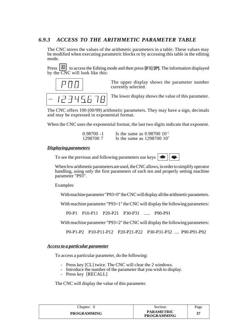
PageChapter: 6 Section:
PROGRAMMING 37PARAMETRICPROGRAMMING
6.9.3 ACCESS TO THE ARITHMETIC PARAMETER TABLE
The CNC stores the values of the arithmetic parameters in a table. These values maybe modified when executing parametric blocks or by accessing this table in the editingmode.
Press to access the Editing mode and then press [F1] [P]. The information displayedby the CNC will look like this:
The upper display shows the parameter numbercurrently selected.
The lower display shows the value of this parameter.
The CNC offers 100 (00/99) arithmetic parameters. They may have a sign, decimalsand may be expressed in exponential format.
When the CNC uses the exponential format, the last two digits indicate that exponent.
0.98700 -1 Is the same as 0.98700 10-1
1298700 7 Is the same as 1298700 107
Displaying parameters
To see the previous and following parameters use keys
When few arithmetic parameters are used, the CNC allows, in order to simplify operatorhandling, using only the first parameters of each ten and properly setting machineparameter "P93".
Examples:
With machine parameter "P93=0" the CNC will display all the arithmetic parameters.
With machine parameter "P93=1" the CNC will display the following parameters:
P0-P1 P10-P11 P20-P21 P30-P31 ..... P90-P91
With machine parameter "P93=2" the CNC will display the following parameters:
P0-P1-P2 P10-P11-P12 P20-P21-P22 P30-P31-P32 .... P90-P91-P92
Access to a particular parameter
To access a particular parameter, do the following:
- Press key [CL] twice. The CNC will clear the 2 windows.- Introduce the number of the parameter that you wish to display.- Press key [RECALL]
The CNC will display the value of this parameter.
Section:Page
PROGRAMMING38
Chapter: 6
Assign a value to a parameter
To assign a value to a specific parameter, do the following:
- Select the parameter required.- Press key [CL]. The CNC will clear the lower window.- Introduce the value required.- Press key [ENTER]
PARAMETRICPROGRAMMING
PageChapter: 6 Section:
PROGRAMMING 39
6.9.4 UNCONDITIONAL JUMP FUNCTION (G25)
Function G25 may be used in two ways:
* To jump to the desired block within the same program and continue executingfrom that block on.
* To execute a particular section (between any two blocks) of the program severaltimes.
After executing this program section the desired number of times, the programwill continue executing from the block after the one containing the jump.
The block containing function G25 may not have any other functions.
G25 as jump to another jump
With this function, it is possible to have the program jump to the desired blockwithin the same program and continue executing from that block on.
Write "G25" followed by the destination block number.
The destination block number may be indicated by either a number (N010 G25N50) or an arithmetic parameter (N010 G25 NP10).
Programming example: N000 G00 X100N005 Y50N010 G25 N50N015 X50N020 Y70N050 G01 X20
When reaching block N010, the program jumps to block N050 and it continuesrunning from this block on, thus skipping blocks N015 and N020.
G25 to execute a section of the program
With this function, it is possible to execute a particular section (between any twoblocks) of the program several times.
After executing this program section the desired number of times, the programwill continue executing from the block after the one containing the jump.
Write "G25" followed by the first block number of the section to be executed. Forexample: N030 G25 N5
After that, press [.] and key in the last block number of the section to be executed.For example: N030 G25 N5.20
PARAMETRICPROGRAMMING
Section:Page
PROGRAMMING40
Chapter: 6
Then, press [.] and key in the number of times this section is to be executed. Forexample: N030 G25 N5.20.81
If the number of repetitions is not indicated, the CNC assumes a value of "1"meaning that it will only execute it once. For example: N030 G25 N5.20 is thesame as N030 G25 N5.20.1
When using a parameter to indicate the program section to be executed, all threefields of the G25 statement will be parametric. For example: when programmingN123 G25 NP10.20.30 the CNC interprets the first block of the section to be theone indicated by parameter P10, the last block of the section will be the one indicatedby P20 (not necessarily block N020) and it will be executed the number of timesindicated by parameter P30 (not necessarily 30 times).
Up to 15 nesting levels may be programmed, which means that it is possible to callfrom one section to another and from this one to another and so on up to 15 levels.Each level may be repeated 99 times.
Attention:
If the last block of the program section to be executed is empty, the CNCwill issue error 7.
Programming example: N000 G00 X10 M3N005 Y20N010 G01 X50N015 G00 Y0N020 X0N025 Y10N030 G25 N5.20.81N035 Y22
The program starts running at block N000. When it reaches block N030, theCNC executes the section between blocks N005 and N020 (both included) 81times.
Then, it continues running from block N035.
PARAMETRICPROGRAMMING
PageChapter: 6 Section:
PROGRAMMING 41
6.9.5 CONDITIONAL JUMP FUNCTIONS (G26, G27, G28, G29)
They are similar to function G25 (unconditional jump).
Functions G26, G27, G28 and G29, before jumping to the indicated block or executingthe indicated program section, check whether the required condition is met or not.
G26 Jump if zero. The "if zero" condition must be met.G27 Jump if not zero. The "if zero" condition must not be met.G28 Jump if less than zero. The "less than" condition must be met.G29 Jump if equal or greater than zero. The "less than" condition must not be met.
The "If zero" condition ("equal to" flag) is met in the following cases:
* When the result of an operation is zero.Example: N001 P1 P3 F2 K5 If P3 = 5
* When both sides of a comparison are identical.Example: N002 P1 F11 K8 If P1 = 8
The "Less than" (negative flag) condition is met in the following cases:
* When the result of an operation is less than zero (negative).Example: N001 P1 P3 F2 K5 If P3 < 5
* When the first operand of a comparison is smaller than the second operand.Example: N002 P1 F11 K8 If P1 < 8
Attention:
The assignments and non-parametric functions do not alter the status ofthe condition flags.
Programming example: N060 P2 F11 K22N065 G01 X10N070 Y20N071 G26 N100N072 G28 N200N073 G29 N300
Block N060 makes a comparison.Blocks N65 and N70 do not alter the condition flags.Therefore: If P2 = 22, The program continues at block N100
If P2 < 22, The program continues at block N200If P2 > 22, The program continues at block N300
Care must be taken when programming functions G26 and G29. If in the previousexample, the following were programmed, instead:
N071 G28 N200N072 G29 N300N073 G26 N100
The program would not execute block N073 since with P2 < 22 it jumps to N200 andwith P > 22 it jumps to N300.
PARAMETRICPROGRAMMING
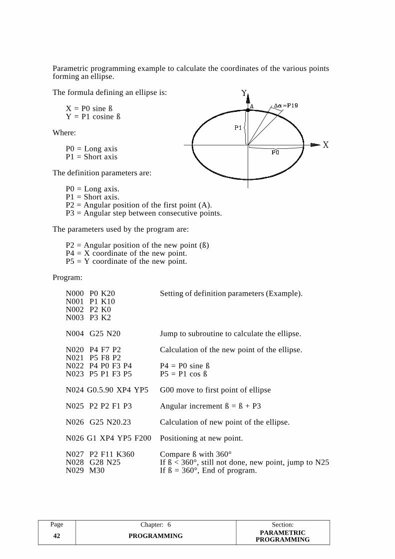
Section:Page
PROGRAMMING42
Chapter: 6
Parametric programming example to calculate the coordinates of the various pointsforming an ellipse.
The formula defining an ellipse is:
X = P0 sine ßY = P1 cosine ß
Where:
P0 = Long axisP1 = Short axis
The definition parameters are:
P0 = Long axis.P1 = Short axis.P2 = Angular position of the first point (A).P3 = Angular step between consecutive points.
The parameters used by the program are:
P2 = Angular position of the new point (ß)P4 = X coordinate of the new point.P5 = Y coordinate of the new point.
Program:
N000 P0 K20 Setting of definition parameters (Example).N001 P1 K10N002 P2 K0N003 P3 K2
N004 G25 N20 Jump to subroutine to calculate the ellipse.
N020 P4 F7 P2 Calculation of the new point of the ellipse.N021 P5 F8 P2N022 P4 P0 F3 P4 P4 = P0 sine ßN023 P5 P1 F3 P5 P5 = P1 cos ß
N024 G0.5.90 XP4 YP5 G00 move to first point of ellipse
N025 P2 P2 F1 P3 Angular increment ß = ß + P3
N026 G25 N20.23 Calculation of new point of the ellipse.
N026 G1 XP4 YP5 F200 Positioning at new point.
N027 P2 F11 K360 Compare ß with 360°N028 G28 N25 If ß < 360°, still not done, new point, jump to N25N029 M30 If ß = 360°, End of program.
PARAMETRICPROGRAMMING
ERRORCODES
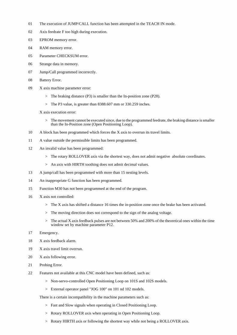
01 The execution of JUMP/CALL function has been attempted in the TEACH IN mode.
02 Axis feedrate F too high during execution.
03 EPROM memory error.
04 RAM memory error.
05 Parameter CHECKSUM error.
06 Strange data in memory.
07 Jump/Call programmed incorrectly.
08 Battery Error.
09 X axis machine parameter error:
> The braking distance (P3) is smaller than the In-position zone (P28).
> The P3 value, is greater than 8388.607 mm or 330.259 inches.
X axis execution error:
> The movement cannot be executed since, due to the programmed feedrate, the braking distance is smallerthan the In-Position zone (Open Positioning Loop).
10 A block has been programmed which forces the X axis to overrun its travel limits.
11 A value outside the permissible limits has been programmed.
12 An invalid value has been programmed:
> The rotary ROLLOVER axis via the shortest way, does not admit negative absolute coordinates.
> An axis with HIRTH toothing does not admit decimal values.
13 A jump/call has been programmed with more than 15 nesting levels.
14 An inappropriate G function has been programmed.
15 Function M30 has not been programmed at the end of the program.
16 X axis not controlled:
> The X axis has shifted a distance 16 times the in-position zone once the brake has been activated.
> The moving direction does not correspond to the sign of the analog voltage.
> The actual X axis feedback pulses are not between 50% and 200% of the theoretical ones within the timewindow set by machine parameter P12.
17 Emergency.
18 X axis feedback alarm.
19 X axis travel limit overrun.
20 X axis following error.
21 Probing Error.
22 Features not available at this CNC model have been defined, such as:
> Non-servo-controlled Open Positioning Loop on 101S and 102S models.
> External operator panel "JOG 100" on 101 nd 102 models.
There is a certain incompatibility in the machine parameters such as:
> Fast and Slow signals when operating in Closed Positioning Loop.
> Rotary ROLLOVER axis when operating in Open Positioning Loop.
> Rotary HIRTH axis or following the shortest way while not being a ROLLOVER axis.
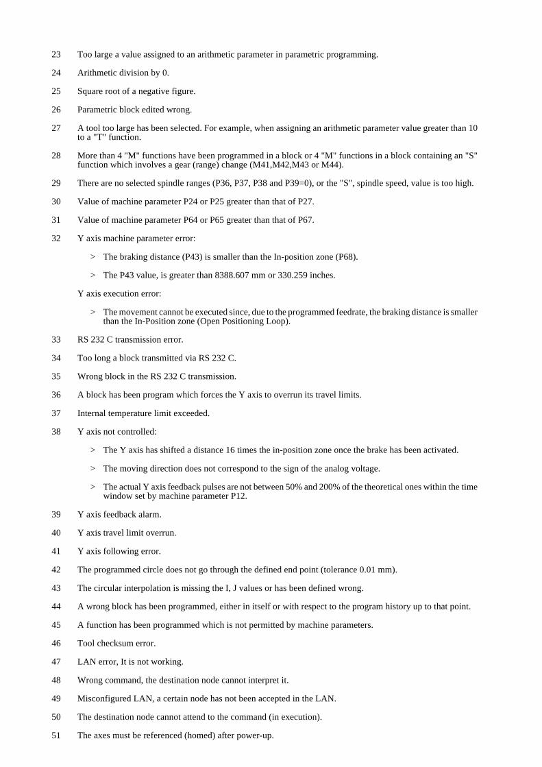
23 Too large a value assigned to an arithmetic parameter in parametric programming.
24 Arithmetic division by 0.
25 Square root of a negative figure.
26 Parametric block edited wrong.
27 A tool too large has been selected. For example, when assigning an arithmetic parameter value greater than 10to a "T" function.
28 More than 4 "M" functions have been programmed in a block or 4 "M" functions in a block containing an "S"function which involves a gear (range) change (M41,M42,M43 or M44).
29 There are no selected spindle ranges (P36, P37, P38 and P39=0), or the "S", spindle speed, value is too high.
30 Value of machine parameter P24 or P25 greater than that of P27.
31 Value of machine parameter P64 or P65 greater than that of P67.
32 Y axis machine parameter error:
> The braking distance (P43) is smaller than the In-position zone (P68).
> The P43 value, is greater than 8388.607 mm or 330.259 inches.
Y axis execution error:
> The movement cannot be executed since, due to the programmed feedrate, the braking distance is smallerthan the In-Position zone (Open Positioning Loop).
33 RS 232 C transmission error.
34 Too long a block transmitted via RS 232 C.
35 Wrong block in the RS 232 C transmission.
36 A block has been program which forces the Y axis to overrun its travel limits.
37 Internal temperature limit exceeded.
38 Y axis not controlled:
> The Y axis has shifted a distance 16 times the in-position zone once the brake has been activated.
> The moving direction does not correspond to the sign of the analog voltage.
> The actual Y axis feedback pulses are not between 50% and 200% of the theoretical ones within the timewindow set by machine parameter P12.
39 Y axis feedback alarm.
40 Y axis travel limit overrun.
41 Y axis following error.
42 The programmed circle does not go through the defined end point (tolerance 0.01 mm).
43 The circular interpolation is missing the I, J values or has been defined wrong.
44 A wrong block has been programmed, either in itself or with respect to the program history up to that point.
45 A function has been programmed which is not permitted by machine parameters.
46 Tool checksum error.
47 LAN error, It is not working.
48 Wrong command, the destination node cannot interpret it.
49 Misconfigured LAN, a certain node has not been accepted in the LAN.
50 The destination node cannot attend to the command (in execution).
51 The axes must be referenced (homed) after power-up.
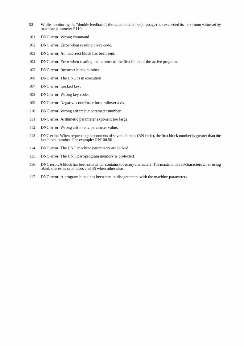
52 While monitoring the "double feedback", the actual deviation (slippage) has exceeded its maximum value set bymachine parameter P110.
101 DNC error. Wrong command.
102 DNC error. Error when reading a key code.
103 DNC error. An incorrect block has been sent.
104 DNC error. Error when reading the number of the first block of the active program.
105 DNC error. Incorrect block number.
106 DNC error. The CNC is in execution
107 DNC error. Locked key.
108 DNC error. Wrong key code.
109 DNC error. Negative coordinate for a rollover axis.
110 DNC error. Wrong arithmetic parameter number.
111 DNC error. Arithmetic parameter exponent too large.
112 DNC error. Wrong arithmetic parameter value.
113 DNC error. When requesting the contents of several blocks (RN code), the first block number is greater than thelast block number. For example: RN100.50
114 DNC error. The CNC machine parameters are locked.
115 DNC error. The CNC part-program memory is protected.
116 DNC error. A block has been sent which contains too many characters. The maximum is 80 characters when usingblank spaces as separators and 45 when otherwise.
117 DNC error. A program block has been sent in disagreement with the machine parameters.