Embed Size (px)
Citation preview
1
TNC-M13- CNC CONTROLLER
Document: Operation Manual Document #: TNC-M13-m Document Rev: 1.0 Product: CNC controller Product Rev: 1.0 Created: Oct-2013
THIS MANUAL CONTAINS INFORMATION FOR INSTALLING AND OPERATING THE
FOLLOWING PRODUCT:
TNC-M13- CNC CONTROLLER
“TINY CONTROLS” AND THE TINY CONTROLS COMPANY’S LOGO ARE COPYRIGHT OF
TINY CONTROLS (P) LTD. COMPANY. OTHER TRADEMARKS, TRADE NAMES, AND SERVICE
MARKS OWNED OR REGISTERED BY ANY OTHER COMPANY AND USED IN THIS MANUAL
ARE THE PROPERTY OF THEIR RESPECTIVE COMPANIES.
TINY CONTROLS PRIVATE LIMITED C-55, NISHAT PARK, KAKROLA MOR, NEW DELHI, INDIA – 110078 WEB: http://www.tinycontrols.com PHONE: +91-11-2533-1567, +91-991-119-3210
2
CONTENTS 1. SIGNS USED IN MANUAL 4 2. CNC CONTROLLER INCLUDES 6 3. MECHANICAL INSTALLATION 6 4. INTRODUCTION- TNC-M14- CNC CONTROLLER 7 5. FEATURES 8 6. CNC CONTROL BOARD SPECIFICATIONS 9 7. CNC CONTROLLER BOARD TERMINALS 10 8. CONNECTING OUTPUTS 11 9. CONNECTING INPUTS 13 10. CNC CONTROL BOARD CONNECTION WITH PEN DRIVE 15 11. CONNECTION DIAGRAM 16 12. AXES AND SPINDLE OUTPUTS CONNECTIONS WITH DRIVES 17 13. BLOCK MODE AND TOOL ZERO CONNECTIONS 18 14. HOME INPUTS CONNECTIONS WITH HOME SWITCHES 19 15. COOLANT, SPINDLE DRIVE AND VFD CONNECTIONS 19 16. LIMIT INPUTS CONNECTIONS WITH LIMIT SWITCHES 20 17. MOUNTING INSTRUCTIONS 21 18. INPUTS AND OUTPUTS SPECIFICATIONS FOR CONTROL BOARD 22 19. HAND HELD PENDANT 25 20. EMERGENCY BUTTON 28 21. BRIGHTNESS SETTINGS FOR LCD 28 22. KEYS FUNCTIONS IN VARIOUS MODES 29 23. CNC CONTROLLER BOARD CONNECTIONS WITH PENDANT 31 24. DESCRIPTION OF DISPLAYS IN VARIOUS STATES OF MACHINE 32 25. OPERATING THE CNC CONTROLLER 35 26. MAIN MENU 35 27. STRUCTURE TREE FOR MENU FUNCTIONS 36 28. GENERAL SETTINGS 37 29. ACTIVE PROFILE 41 30. AXIS SETTINGS 41 31. IO SETTING 44
a. SPINDLE SETTING 44 b. HOMING SETTING 45 c. HOME SWITCH SETTING 47 d. LIMIT SETTING 48 e. MISC OUTPUTS 49
32. TOOL SETTINGS 50
3
33. DATA FILE 52 34. DEFAULT PROFILES VALUES 54 35. KEY FUNCTIONS: NAVIGATION KEYS 55 36. NUMERIC KEYS 58 37. FEED RATE OVERRIDE AND SPINDLE SPEED OVERRIDE 59 38. G-CODE ALLOWED TO USE † 63 39. M CODES ALLOWED TO USE † 64 40. FORMAT OF A G-CODE LINE 65 41. TROUBLE SHOOTING 67 42. GLOSSARY 69
43. INDEX 71
4
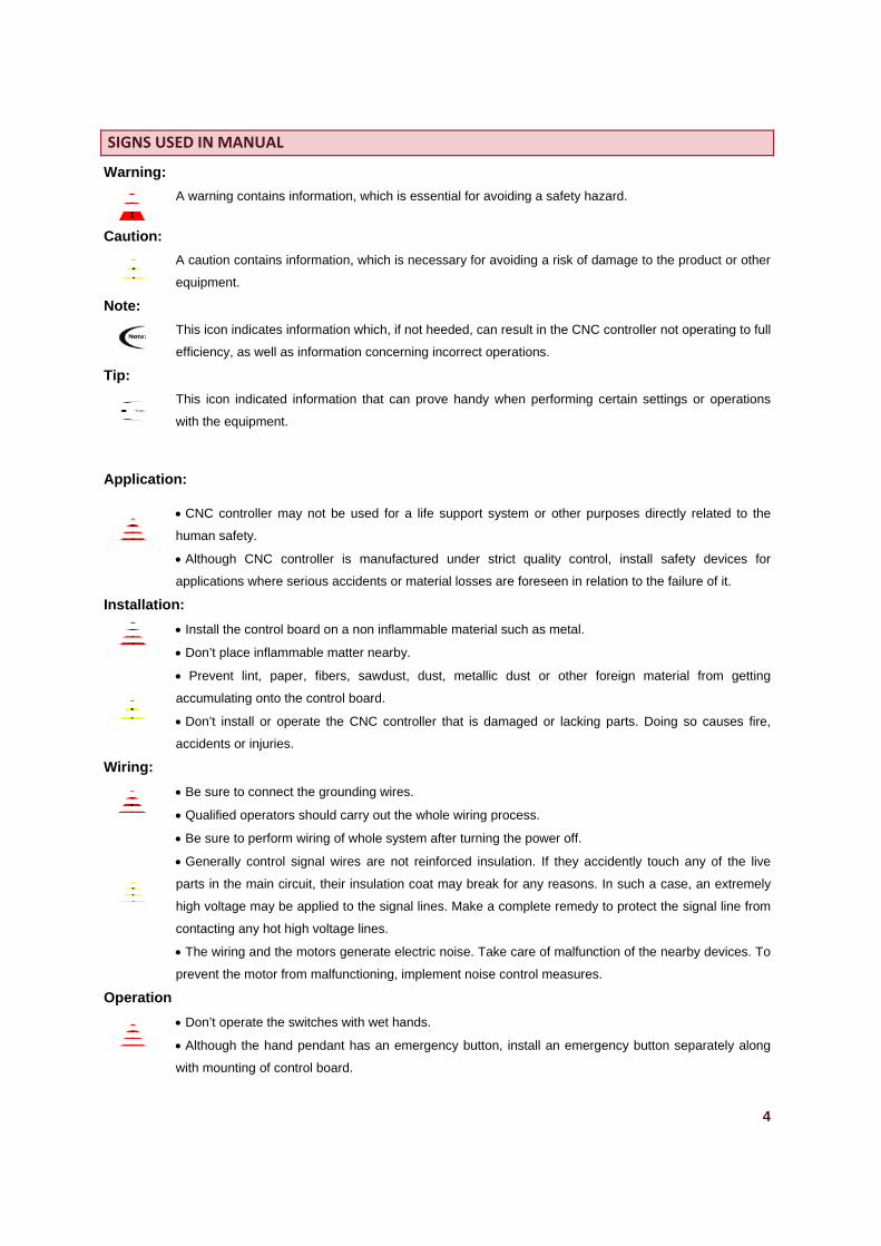
SIGNS USED IN MANUAL
Warning:
A warning contains information, which is essential for avoiding a safety hazard.
Caution:
A caution contains information, which is necessary for avoiding a risk of damage to the product or other
equipment.
Note:
This icon indicates information which, if not heeded, can result in the CNC controller not operating to full
efficiency, as well as information concerning incorrect operations.
Tip:
This icon indicated information that can prove handy when performing certain settings or operations
with the equipment.
Application:
CNC controller may not be used for a life support system or other purposes directly related to the
human safety.
Although CNC controller is manufactured under strict quality control, install safety devices for
applications where serious accidents or material losses are foreseen in relation to the failure of it.
Installation:
Install the control board on a non inflammable material such as metal.
Don’t place inflammable matter nearby.
Prevent lint, paper, fibers, sawdust, dust, metallic dust or other foreign material from getting
accumulating onto the control board.
Don’t install or operate the CNC controller that is damaged or lacking parts. Doing so causes fire,
accidents or injuries.
Wiring:
Be sure to connect the grounding wires.
Qualified operators should carry out the whole wiring process.
Be sure to perform wiring of whole system after turning the power off.
Generally control signal wires are not reinforced insulation. If they accidently touch any of the live
parts in the main circuit, their insulation coat may break for any reasons. In such a case, an extremely
high voltage may be applied to the signal lines. Make a complete remedy to protect the signal line from
contacting any hot high voltage lines.
The wiring and the motors generate electric noise. Take care of malfunction of the nearby devices. To
prevent the motor from malfunctioning, implement noise control measures.
Operation
Don’t operate the switches with wet hands.
Although the hand pendant has an emergency button, install an emergency button separately along
with mounting of control board.
5
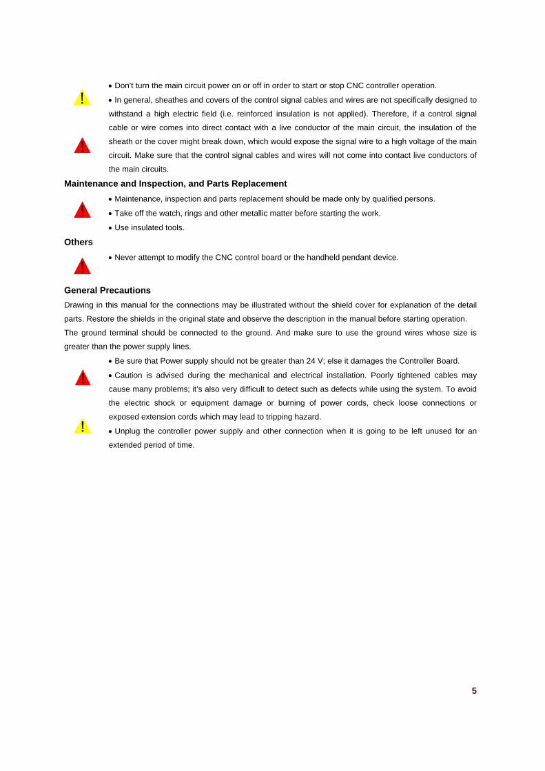
Don’t turn the main circuit power on or off in order to start or stop CNC controller operation.
In general, sheathes and covers of the control signal cables and wires are not specifically designed to
withstand a high electric field (i.e. reinforced insulation is not applied). Therefore, if a control signal
cable or wire comes into direct contact with a live conductor of the main circuit, the insulation of the
sheath or the cover might break down, which would expose the signal wire to a high voltage of the main
circuit. Make sure that the control signal cables and wires will not come into contact live conductors of
the main circuits.
Maintenance and Inspection, and Parts Replacement
Maintenance, inspection and parts replacement should be made only by qualified persons.
Take off the watch, rings and other metallic matter before starting the work.
Use insulated tools.
Others
Never attempt to modify the CNC control board or the handheld pendant device.
General Precautions
Drawing in this manual for the connections may be illustrated without the shield cover for explanation of the detail
parts. Restore the shields in the original state and observe the description in the manual before starting operation.
The ground terminal should be connected to the ground. And make sure to use the ground wires whose size is
greater than the power supply lines.
Be sure that Power supply should not be greater than 24 V; else it damages the Controller Board.
Caution is advised during the mechanical and electrical installation. Poorly tightened cables may
cause many problems; it’s also very difficult to detect such as defects while using the system. To avoid
the electric shock or equipment damage or burning of power cords, check loose connections or
exposed extension cords which may lead to tripping hazard.
Unplug the controller power supply and other connection when it is going to be left unused for an
extended period of time.
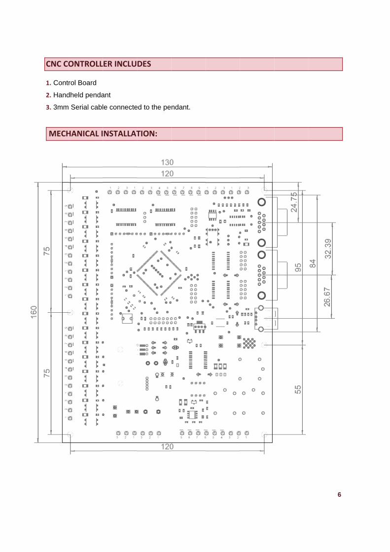
CNC CO
1. Contr
2. Hand
3. 3mm
MECH
ONTROLL
rol Board
dheld penda
Serial cabl
HANICAL I
LER INCLU
ant
le connecte
NSTALLAT
DES
ed to the pe
TION:
ndant.
6
7
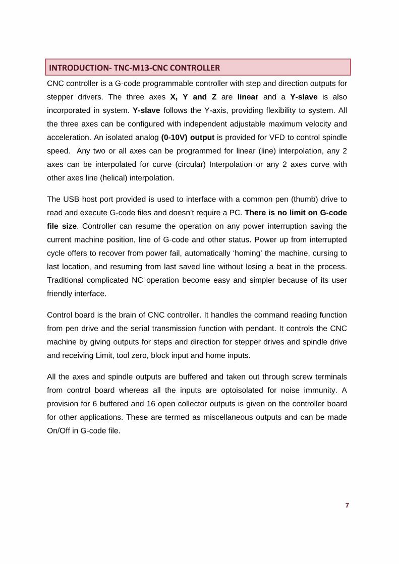
INTRODUCTION‐ TNC‐M13‐CNC CONTROLLER
CNC controller is a G-code programmable controller with step and direction outputs for
stepper drivers. The three axes X, Y and Z are linear and a Y-slave is also
incorporated in system. Y-slave follows the Y-axis, providing flexibility to system. All
the three axes can be configured with independent adjustable maximum velocity and
acceleration. An isolated analog (0-10V) output is provided for VFD to control spindle
speed. Any two or all axes can be programmed for linear (line) interpolation, any 2
axes can be interpolated for curve (circular) Interpolation or any 2 axes curve with
other axes line (helical) interpolation.
The USB host port provided is used to interface with a common pen (thumb) drive to
read and execute G-code files and doesn’t require a PC. There is no limit on G-code
file size. Controller can resume the operation on any power interruption saving the
current machine position, line of G-code and other status. Power up from interrupted
cycle offers to recover from power fail, automatically ‘homing’ the machine, cursing to
last location, and resuming from last saved line without losing a beat in the process.
Traditional complicated NC operation become easy and simpler because of its user
friendly interface.
Control board is the brain of CNC controller. It handles the command reading function
from pen drive and the serial transmission function with pendant. It controls the CNC
machine by giving outputs for steps and direction for stepper drives and spindle drive
and receiving Limit, tool zero, block input and home inputs.
All the axes and spindle outputs are buffered and taken out through screw terminals
from control board whereas all the inputs are optoisolated for noise immunity. A
provision for 6 buffered and 16 open collector outputs is given on the controller board
for other applications. These are termed as miscellaneous outputs and can be made
On/Off in G-code file.
8
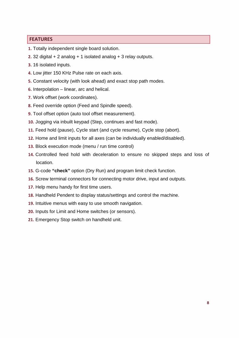
FEATURES
1. Totally independent single board solution.
2. 32 digital + 2 analog + 1 isolated analog + 3 relay outputs.
3. 16 isolated inputs.
4. Low jitter 150 KHz Pulse rate on each axis.
5. Constant velocity (with look ahead) and exact stop path modes.
6. Interpolation – linear, arc and helical.
7. Work offset (work coordinates).
8. Feed override option (Feed and Spindle speed).
9. Tool offset option (auto tool offset measurement).
10. Jogging via inbuilt keypad (Step, continues and fast mode).
11. Feed hold (pause), Cycle start (and cycle resume), Cycle stop (abort).
12. Home and limit inputs for all axes (can be individually enabled/disabled).
13. Block execution mode (menu / run time control)
14. Controlled feed hold with deceleration to ensure no skipped steps and loss of
location.
15. G-code “check” option (Dry Run) and program limit check function.
16. Screw terminal connectors for connecting motor drive, input and outputs.
17. Help menu handy for first time users.
18. Handheld Pendent to display status/settings and control the machine.
19. Intuitive menus with easy to use smooth navigation.
20. Inputs for Limit and Home switches (or sensors).
21. Emergency Stop switch on handheld unit.
9
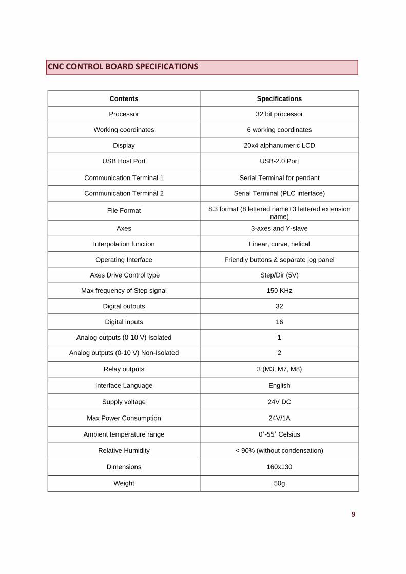
CNC CONTROL BOARD SPECIFICATIONS
Contents Specifications
Processor 32 bit processor
Working coordinates
6 working coordinates
Display 20x4 alphanumeric LCD
USB Host Port USB-2.0 Port
Communication Terminal 1 Serial Terminal for pendant
Communication Terminal 2 Serial Terminal (PLC interface)
File Format
8.3 format (8 lettered name+3 lettered extension name)
Axes 3-axes and Y-slave
Interpolation function
Linear, curve, helical
Operating Interface
Friendly buttons & separate jog panel
Axes Drive Control type
Step/Dir (5V)
Max frequency of Step signal
150 KHz
Digital outputs
32
Digital inputs
16
Analog outputs (0-10 V) Isolated
1
Analog outputs (0-10 V) Non-Isolated
2
Relay outputs
3 (M3, M7, M8)
Interface Language
English
Supply voltage
24V DC
Max Power Consumption
24V/1A
Ambient temperature range
0˚-55˚ Celsius
Relative Humidity
< 90% (without condensation)
Dimensions
160x130
Weight
50g
TO
BLO
M
M
Y‐SLAV
M
M
M
M
CNC C
24 V
OOL ZERO IN
CK MODE IN
MISC INPUT 1
MISC INPUT 2
GND
24 V
X HOME
INY HOME IN
Z HOME IN
VE HOME IN
GND
24 V
X‐LIMIT IN
Y‐LIMIT IN
Z‐LIMIT IN
GND
24 V
MISC INPUT 3
MISC INPUT 4
MISC INPUT 5
MISC INPUT 6
GND
CONTROLLLER BOAR
GND
24 V IN
X DIR OUT
X STEP
OUT
COM
RD TERMIN
5VOUT
GND
12 V OUT
GND
COM
Y DIR OUT
Y STEP
OUT
COM
1
2
3
J4
NALS
10VANALO
GIN
GND
ZDIR
OUT
Z STEP OUT
COM
Y‐SLA
VEDIR
OUT
J5
COM
NO
0V IN
0‐10VANALO
GOUT
Y‐ SLA
VE STEP
OUT
COM
SPINDLE
DIR
OUT
SPINDLE ST
EP OUT
SPINDLE
COMNO
COMNO
GND
ANALO
G OUT 1
(0‐10V)
ANALO
G OUT 2 (0
‐
AGND
J2
COOLA
NT MIST
COOLA
NT FLOOD
COM
J3
10
Misc Outputs 1‐
Misc Outputs
Misc Outputs
Conn
to Pe
Pen drive
‐6
7‐14
15‐22
nection
endant
e slot
11
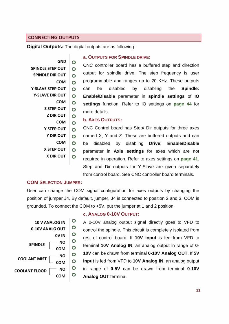
CONNECTING OUTPUTS
Digital Outputs: The digital outputs are as following:
a. OUTPUTS FOR SPINDLE DRIVE:
CNC controller board has a buffered step and direction
output for spindle drive. The step frequency is user
programmable and ranges up to 20 KHz. These outputs
can be disabled by disabling the Spindle:
Enable/Disable parameter in spindle settings of IO
settings function. Refer to IO settings on page 44 for
more details.
b. AXES OUTPUTS:
CNC Control board has Step/ Dir outputs for three axes
named X, Y and Z. These are buffered outputs and can
be disabled by disabling Drive: Enable/Disable
parameter in Axis settings for axes which are not
required in operation. Refer to axes settings on page 41.
Step and Dir outputs for Y-Slave are given separately
from control board. See CNC controller board terminals.
COM SELECTION JUMPER:
User can change the COM signal configuration for axes outputs by changing the
position of jumper J4. By default, jumper, J4 is connected to position 2 and 3, COM is
grounded. To connect the COM to +5V, put the jumper at 1 and 2 position.
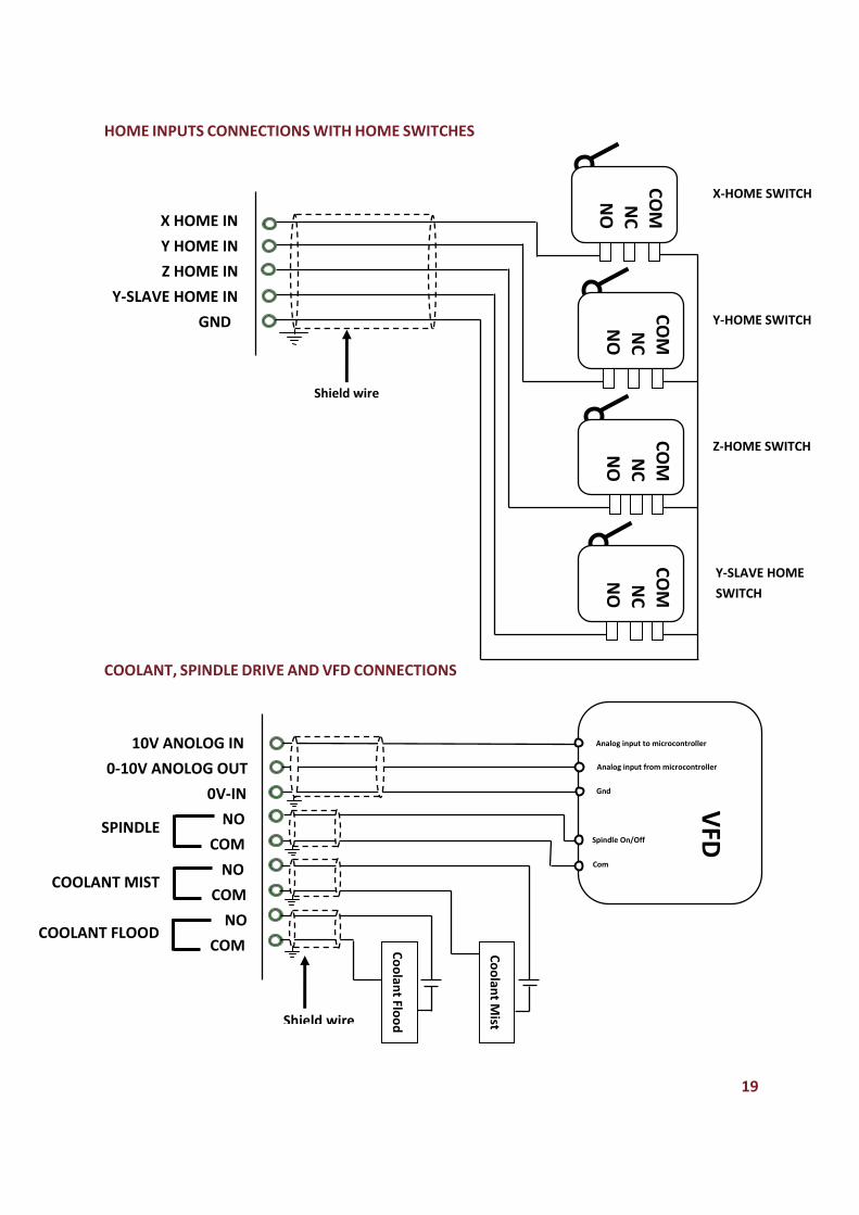
c. ANALOG 0-10V OUTPUT:
A 0-10V analog output signal directly goes to VFD to
control the spindle. This circuit is completely isolated from
rest of control board. If 10V input is fed from VFD to
terminal 10V Analog IN; an analog output in range of 0-
10V can be drawn from terminal 0-10V Analog OUT. If 5V
input is fed from VFD to 10V Analog IN, an analog output
in range of 0-5V can be drawn from terminal 0-10V
Analog OUT terminal.
GND
SPINDLE STEP OUT
SPINDLE DIR OUT
COM
Y‐SLAVE STEP OUT
Y‐SLAVE DIR OUT
COM
Z STEP OUT
Z DIR OUT
COM
Y STEP OUT
Y DIR OUT
COM
X STEP OUT
X DIR OUT
10 V ANALOG IN
0‐10V ANALG OUT
0V IN
NO
COM
NO
COM
NO
COM
SPINDLE
COOLANT MIST
COOLANT FLOOD
12
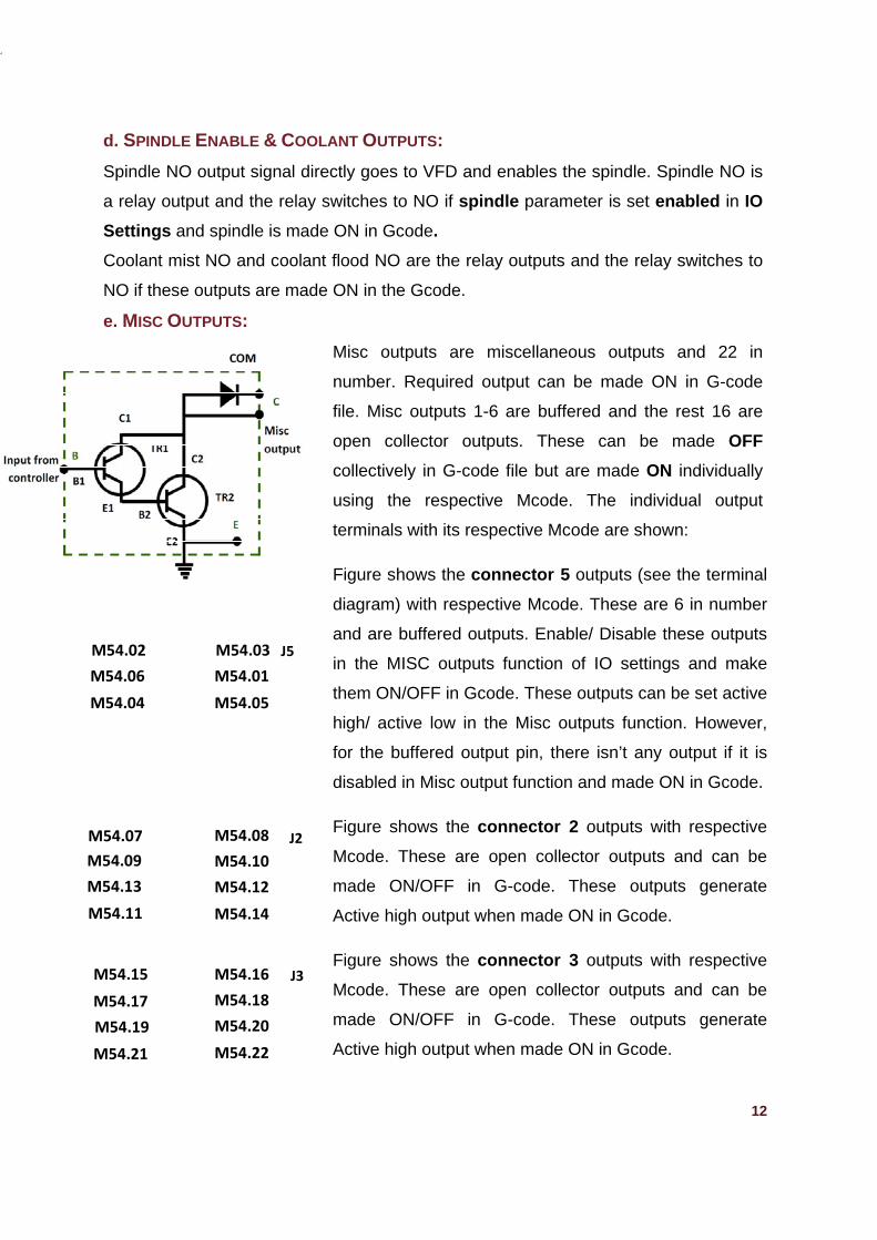
d. SPINDLE ENABLE & COOLANT OUTPUTS:
Spindle NO output signal directly goes to VFD and enables the spindle. Spindle NO is
a relay output and the relay switches to NO if spindle parameter is set enabled in IO
Settings and spindle is made ON in Gcode.
Coolant mist NO and coolant flood NO are the relay outputs and the relay switches to
NO if these outputs are made ON in the Gcode.
e. MISC OUTPUTS:
Misc outputs are miscellaneous outputs and 22 in
number. Required output can be made ON in G-code
file. Misc outputs 1-6 are buffered and the rest 16 are
open collector outputs. These can be made OFF
collectively in G-code file but are made ON individually
using the respective Mcode. The individual output
terminals with its respective Mcode are shown:
Figure shows the connector 5 outputs (see the terminal
diagram) with respective Mcode. These are 6 in number
and are buffered outputs. Enable/ Disable these outputs
in the MISC outputs function of IO settings and make
them ON/OFF in Gcode. These outputs can be set active
high/ active low in the Misc outputs function. However,
for the buffered output pin, there isn’t any output if it is
disabled in Misc output function and made ON in Gcode.
Figure shows the connector 2 outputs with respective
Mcode. These are open collector outputs and can be
made ON/OFF in G-code. These outputs generate
Active high output when made ON in Gcode.
Figure shows the connector 3 outputs with respective
Mcode. These are open collector outputs and can be
made ON/OFF in G-code. These outputs generate
Active high output when made ON in Gcode.
M54.03
M54.01
M54.05
M54.07
M54.09
M54.13
M54.11
M54.08
M54.10
M54.12
M54.14
M54.16
M54.18
M54.20
M54.22
M54.15
M54.17
M54.19
M54.21
M54.02
M54.06
M54.04
J5
J2
J3
13
M54.01-M54.22: To make the Misc output ON.
M55.01-M55.22: To make the Misc output OFF.
M56: Execution of this Mcode switches OFF all the Misc outputs.
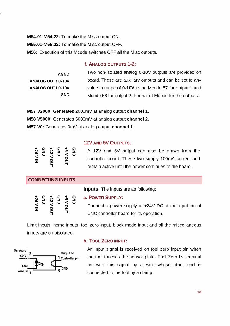
f. ANALOG OUTPUTS 1-2:
Two non-isolated analog 0-10V outputs are provided on
board. These are auxiliary outputs and can be set to any
value in range of 0-10V using Mcode 57 for output 1 and
Mcode 58 for output 2. Format of Mcode for the outputs:
M57 V2000: Generates 2000mV at analog output channel 1.
M58 V5000: Generates 5000mV at analog output channel 2.
M57 V0: Generates 0mV at analog output channel 1.
12V AND 5V OUTPUTS:
A 12V and 5V output can also be drawn from the
controller board. These two supply 100mA current and
remain active until the power continues to the board.
CONNECTING INPUTS
Inputs: The inputs are as following:
a. POWER SUPPLY:
Connect a power supply of +24V DC at the input pin of
CNC controller board for its operation.
Limit inputs, home inputs, tool zero input, block mode input and all the miscellaneous
inputs are optoisolated.
b. TOOL ZERO INPUT:
An input signal is received on tool zero input pin when
the tool touches the sensor plate. Tool Zero IN terminal
recieves this signal by a wire whose other end is
connected to the tool by a clamp.
AGND
ANALOG OUT2 0‐10V
ANALOG OUT1 0‐10V
GND
GND
+5 V OUT
GND
+12 V OUT
GND
+24 V IN
+24 V IN
GND
+12 V OUT
GND
+5 V OUT
GND
14
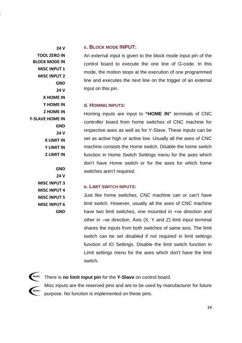
c. BLOCK MODE INPUT:
An external input is given to the block mode input pin of the
control board to execute the one line of G-code. In this
mode, the motion stops at the execution of one programmed
line and executes the next line on the trigger of an external
input on this pin.
d. HOMING INPUTS:
Homing inputs are input to “HOME IN” terminals of CNC
controller board from home switches of CNC machine for
respective axes as well as for Y-Slave. These inputs can be
set as active high or active low. Usually all the axes of CNC
machine consists the Home switch. Disable the home switch
function in Home Switch Settings menu for the axes which
don’t have Home switch or for the axes for which home
switches aren’t required.
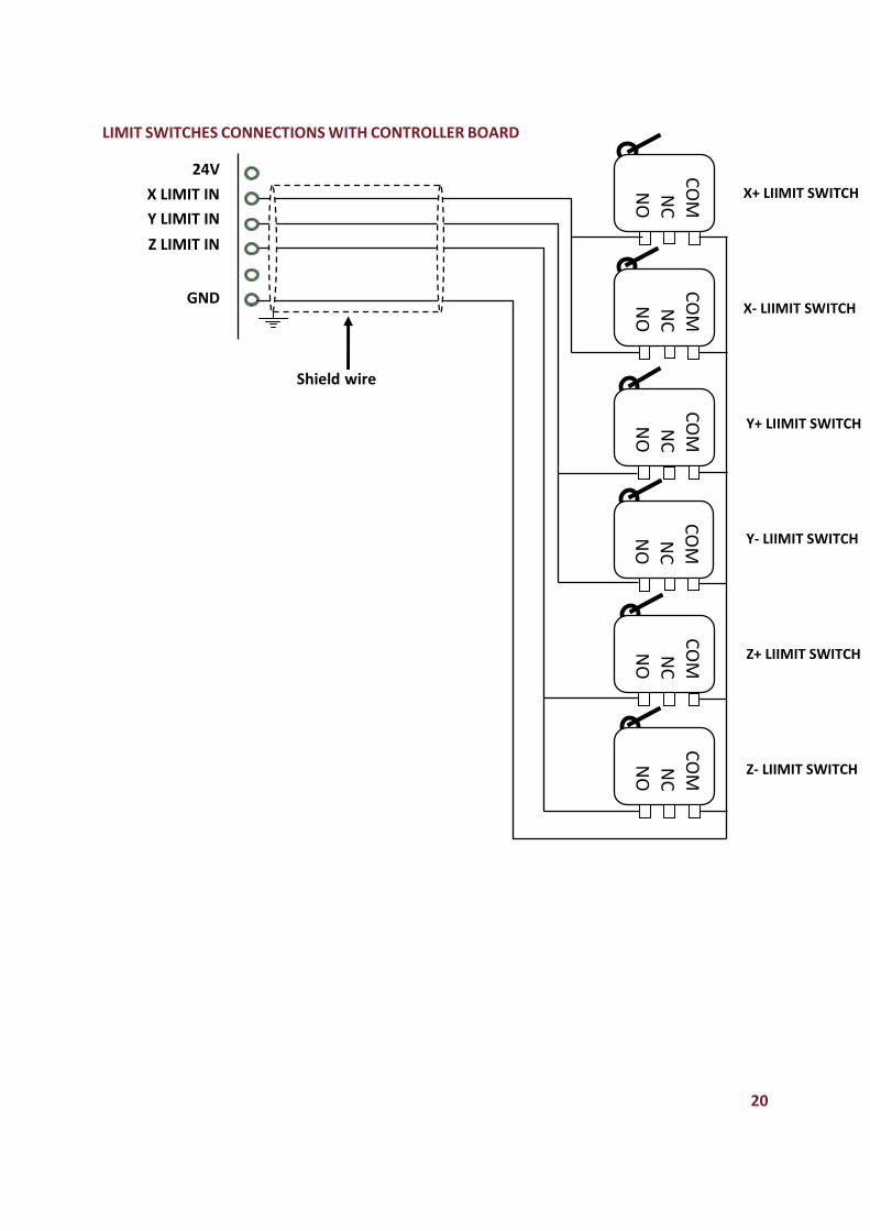
e. LIMIT SWITCH INPUTS:
Just like home switches, CNC machine can or can’t have
limit switch. However, usually all the axes of CNC machine
have two limit switches, one mounted in +ve direction and
other in –ve direction. Axis (X, Y and Z) limit input terminal
shares the inputs from both switches of same axis. The limit
switch can be set disabled if not required in limit settings
function of IO Settings. Disable the limit switch function in
Limit settings menu for the axes which don’t have the limit
switch.
There is no limit input pin for the Y-Slave on control board.
Misc inputs are the reserved pins and are to be used by manufacturer for future
purpose. No function is implemented on these pins.
24 V
TOOL ZERO IN
BLOCK MODE IN
MISC INPUT 1
MISC INPUT 2
GND
24 V
X HOME IN
Y HOME IN
Z HOME IN
Y‐SLAVE HOME IN
GND
24 V
X LIMIT IN
Y LIMIT IN
Z LIMIT IN
GND
24 V
MISC INPUT 3
MISC INPUT 4
MISC INPUT 5
MISC INPUT 6
GND
CNC C
Conne
The LC
The se
board.
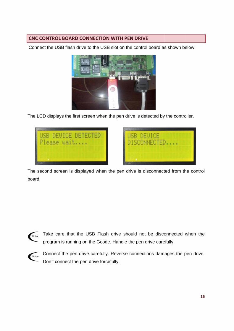
CONTROL
ect the USB
CD displays
econd scre
Take car
program i
Connect t
Don’t con
BOARD C
B flash driv
s the first s
een is disp
re that the
is running
the pen dr
nnect the p
ONNECTIO
ve to the U
screen whe
played whe
e USB Fla
on the Gco
rive carefu
en drive fo
ON WITH
USB slot on
en the pen
en the pen
ash drive
ode. Hand
ully. Revers
orcefully.
PEN DRIV
n the contro
n drive is de
n drive is d
should no
le the pen
se connec
VE
ol board as
etected by
disconnect
ot be disco
drive care
ctions dam
s shown be
y the contro
ted from th
onnected w
efully.
ages the p
15
elow:
oller.
he control
when the
pen drive.
Power Supply to drive
Power Supply to drive
Power Supply to drive
Power Su
pply to drive
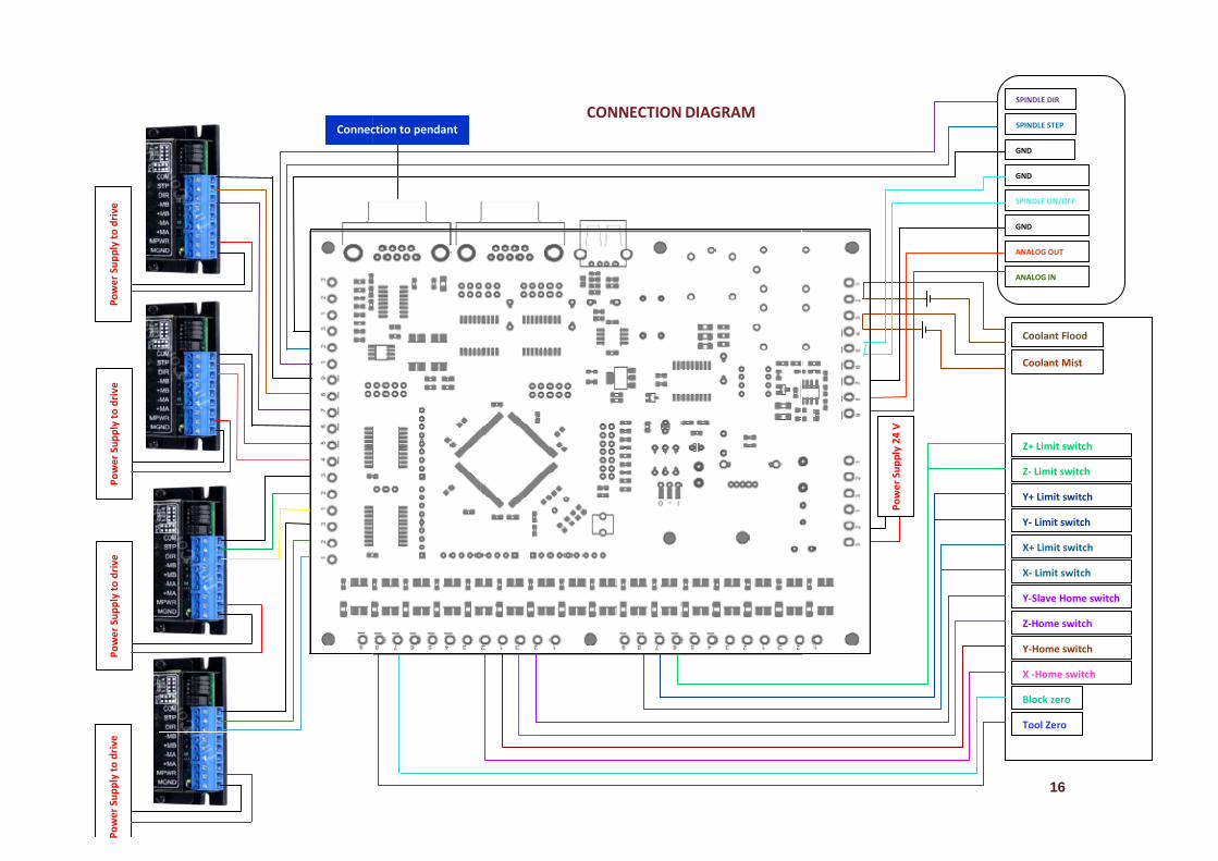
Connecction to pendant CCONNECTION DDIAGRAM
Power Supply 24 V
G
S
G
A
A
G
16
Tool Zero
Block zero
Z‐ Limit switch
X+ Limit switch
Y+ Limit switch
Y‐ Limit switch
X‐ Limit switch
Y‐Slave Home switch
Z‐Home switch
Y‐Home switch
Coolant Mist
Coolant Flood
Z+ Limit switch
X ‐Home switch
SPINDLE DIR
SPINDLE STEP
GND
SPINDLE ON/OFF
GND
ANALOG OUT
ANALOG IN
GND
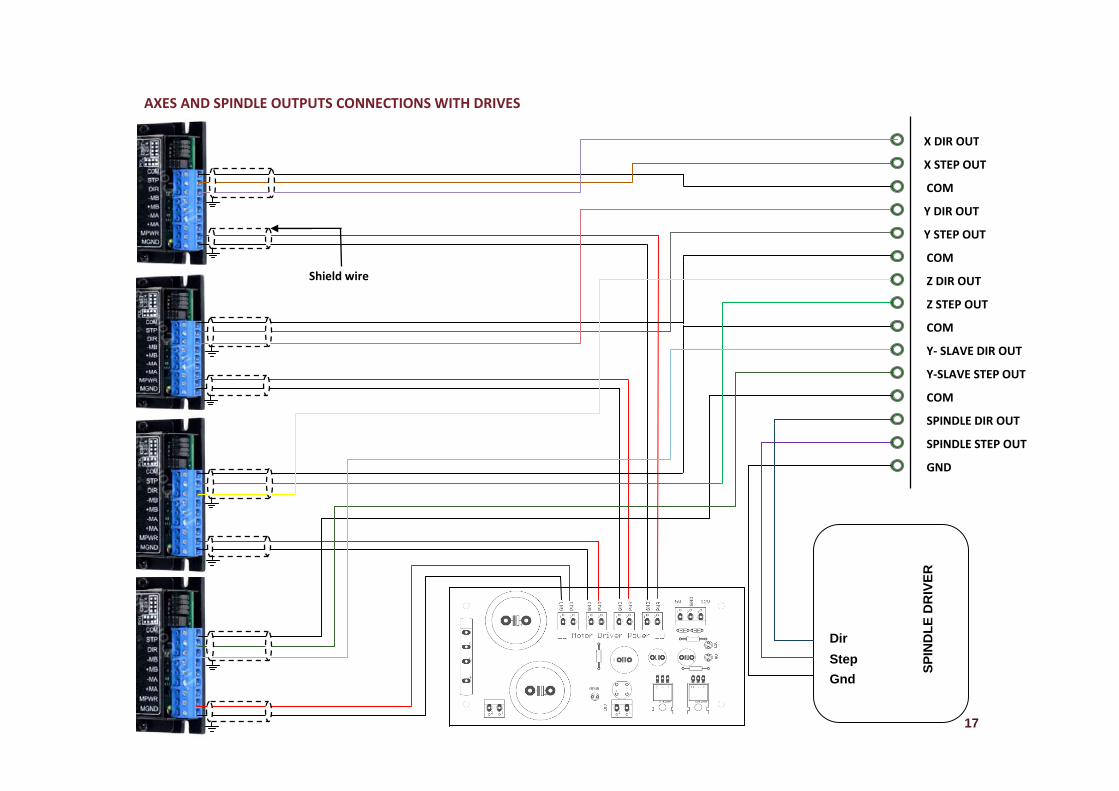
AAXES AND SPINDLE OUTPUTS C
Shield
CONNECTIONS W
wire
WITH DRIVES
D
S
G
X
X
C
Y
Y
C
Z
Z
C
Y
Y
C
S
S
Dir
Step
Gnd
SP
IND
LE
DR
IVE
R
G
17
DIR OUT
STEP OUT
OM
DIR OUT
STEP OUT
OM
DIR OUT
STEP OUT
OM
‐ SLAVE DIR OUT
‐SLAVE STEP OUT
OM
PINDLE DIR OUT
PINDLE STEP OUT
GND
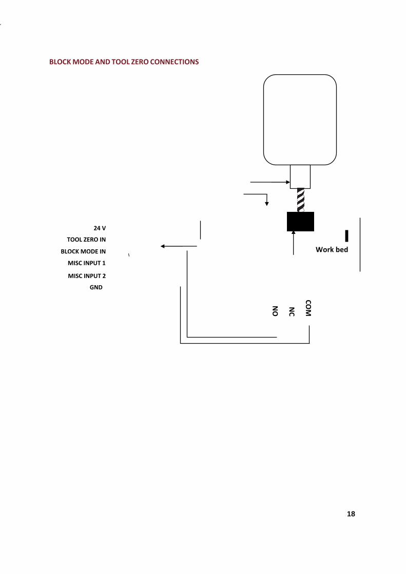
18
BLOCK MODE AND TOOL ZERO CONNECTIONS
Spindle motor
Collet
Sensor Plate
Clip holding wireTool
Shield wire
COM
NC
NO
Work bed
24 V
TOOL ZERO IN
BLOCK MODE IN
MISC INPUT 1
MISC INPUT 2
GND
19
HOME INPUTS CONNECTIONS WITH HOME SWITCHES
COOLANT, SPINDLE DRIVE AND VFD CONNECTIONS
X HOME IN
Y HOME IN
Z HOME IN
Y‐SLAVE HOME IN
COM
NC
NO
COMNC
NO
COMNC
NO
COMNC
NO
X‐HOME SWITCH
Y‐HOME SWITCH
Z‐HOME SWITCH
Y‐SLAVE HOME
SWITCH
GND
10V ANOLOG IN
0‐10V ANOLOG OUT
0V‐IN
NO
COM
NO
COM
NO
COM
SPINDLE
COOLANT FLOOD
COOLANT MIST
Analog input to microcontroller
Analog input from microcontroller
Gnd
Spindle On/Off
Com
VFD
Coolan
t Flood
Coolan
t Mist
Shield wire
Shield wire
20
LIMIT SWITCHES CONNECTIONS WITH CONTROLLER BOARD
v
V
24V
X LIMIT IN
Y LIMIT IN
Z LIMIT IN
GND
COM
NC
NO
COM
NC
NO
COMNC
NO
COMNC
NO
COMNC
NO
COM
NC
NO
Shield wire
X+ LIIMIT SWITCH
X‐ LIIMIT SWITCH
Y+ LIIMIT SWITCH
Y‐ LIIMIT SWITCH
Z+ LIIMIT SWITCH
Z‐ LIIMIT SWITCH
21
MOUNTING INSTRUCTIONS
CNC Controller board can be mounted in a box or can be used open. A proper
arrangement of emergency button must be made in CNC controller board installation. If
possible, board should be placed securely fastened to a smooth, flat surface. A
suitable provision for the ventilation of heat (due to drives of steppers and spindle)
should be installed else it can damage the controller.
1. Never use board in a space where there is no airflow or where ambient temperature
exceeds 55 degree Celsius.
2. Never put board in conditions where humidity is 90% (non-condensing).
3. Don’t use this product with strong magnetic field.
4. Protect it from dust, water and heat. Make sure that there should not be conductive
particles near the control board.
5. Don’t allow any liquid or other foreign body to get on controller board or on pendant.
6. Don’t open the pendant for maintenance or modifications in its structure.
7. Be gentle when plugging in cables and pen drive.
Use the shield cable in connections to prevent the shorting of wires due to wear
and tear of their insulation.
CNC control board should be installed in dust free environment with suitable
temperature and humidity conditions. Read the CNC Controller Specification
table for these parameters.
The device should be operated in the vibration free conditions.
22
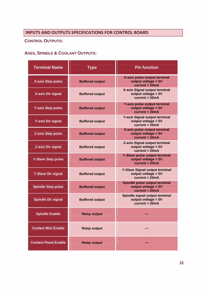
INPUTS AND OUTPUTS SPECIFICATIONS FOR CONTROL BOARD
CONTROL OUTPUTS:
AXES, SPINDLE & COOLANT OUTPUTS:
Terminal Name
Type
Pin function
X-axis Step pulse
Buffered output
X-axis pulse output terminal output voltage = 5V
current = 20mA
X-axis Dir signal
Buffered output
X-axis Signal output terminal output voltage = 5V
current = 20mA
Y-axis Step pulse
Buffered output
Y-axis pulse output terminal output voltage = 5V
current = 20mA
Y-axis Dir signal
Buffered output
Y-axis Signal output terminal output voltage = 5V
current = 20mA
Z-axis Step pulse
Buffered output
Z-axis pulse output terminal output voltage = 5V
current = 20mA
Z-axis Dir signal
Buffered output
Z-axis Signal output terminal output voltage = 5V
current = 20mA
Y-Slave Step pulse
Buffered output
Y-Slave pulse output terminal output voltage = 5V
current = 20mA
Y-Slave Dir signal
Buffered output
Y-Slave Signal output terminal output voltage = 5V
current = 20mA
Spindle Step pulse
Buffered output
Spindle pulse output terminal output voltage = 5V
current = 20mA
Spindle Dir signal
Buffered output
Spindle signal output terminal output voltage = 5V
current = 20mA
Spindle Enable
Relay output
—
Coolant Mist Enable
Relay output
—
Coolant Flood Enable
Relay output
—
23
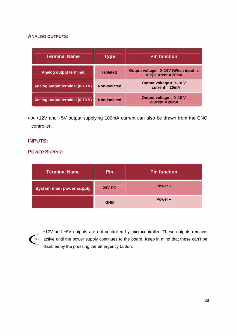
ANALOG OUTPUTS:
A +12V and +5V output supplying 100mA current can also be drawn from the CNC
controller.
INPUTS:
POWER SUPPLY:
+12V and +5V outputs are not controlled by microcontroller. These outputs remains
active until the power supply continues to the board. Keep in mind that these can’t be
disabled by the pressing the emergency button.
Terminal Name
Type
Pin function
Analog output terminal
Isolated
Output voltage =0–10V (When input is 10V) current = 20mA
Analog output terminal (0-10 V)
Non-Isolated
Output voltage = 0–10 V current = 20mA
Analog output terminal (0-10 V)
Non-Isolated
Output voltage = 0–10 V current = 20mA
Terminal Name
Pin
Pin function
System main power supply
24V DC Power +
GND
Power –
24
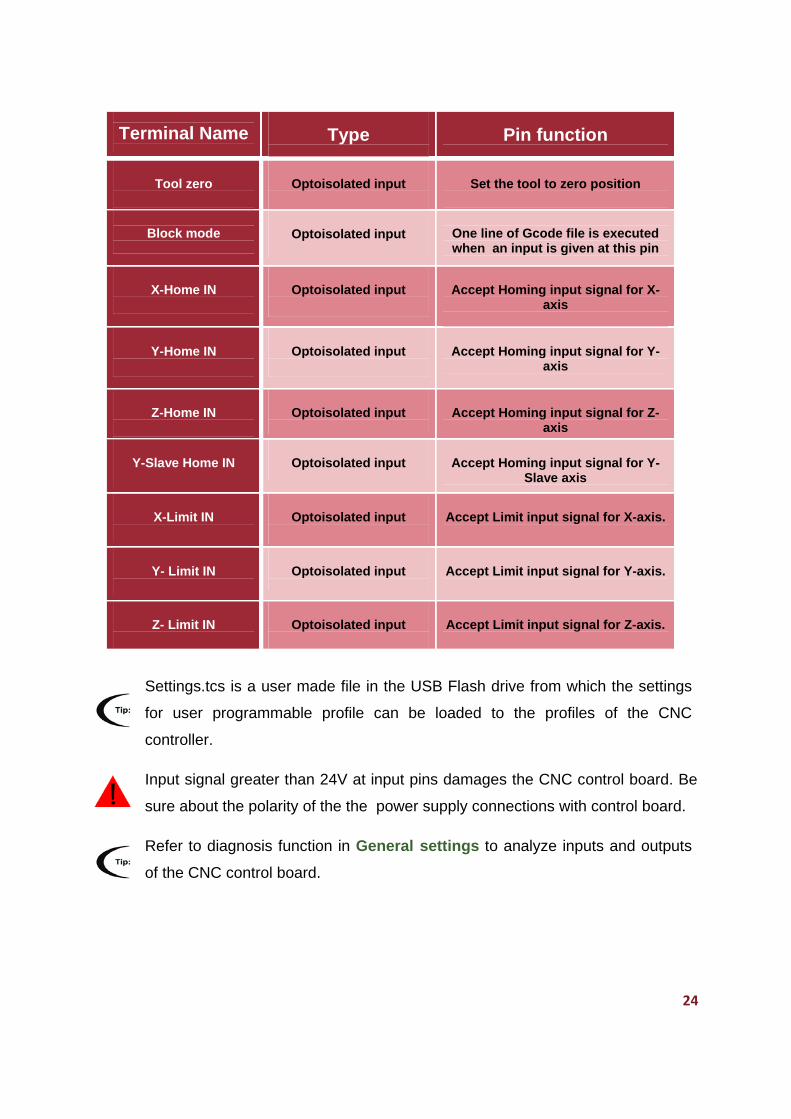
Terminal Name
Type
Pin function
Tool zero
Optoisolated input
Set the tool to zero position
Block mode
Optoisolated input
One line of Gcode file is executed when an input is given at this pin
X-Home IN
Optoisolated input
Accept Homing input signal for X-axis
Y-Home IN
Optoisolated input
Accept Homing input signal for Y-axis
Z-Home IN
Optoisolated input
Accept Homing input signal for Z-axis
Y-Slave Home IN
Optoisolated input
Accept Homing input signal for Y-Slave axis
X-Limit IN
Optoisolated input
Accept Limit input signal for X-axis.
Y- Limit IN
Optoisolated input
Accept Limit input signal for Y-axis.
Z- Limit IN
Optoisolated input
Accept Limit input signal for Z-axis.
Settings.tcs is a user made file in the USB Flash drive from which the settings
for user programmable profile can be loaded to the profiles of the CNC
controller.
Input signal greater than 24V at input pins damages the CNC control board. Be
sure about the polarity of the the power supply connections with control board.
Refer to diagnosis function in General settings to analyze inputs and outputs
of the CNC control board.
25
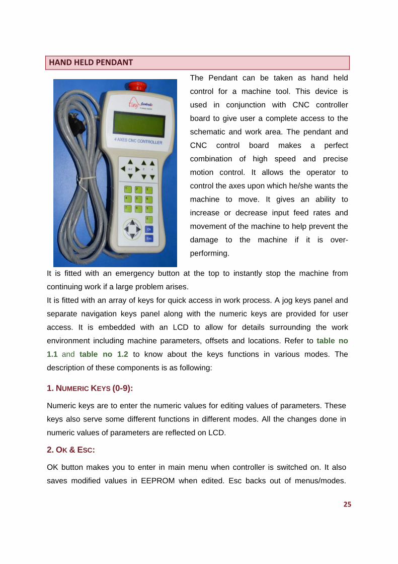
HAND HELD PENDANT
The Pendant can be taken as hand held
control for a machine tool. This device is
used in conjunction with CNC controller
board to give user a complete access to the
schematic and work area. The pendant and
CNC control board makes a perfect
combination of high speed and precise
motion control. It allows the operator to
control the axes upon which he/she wants the
machine to move. It gives an ability to
increase or decrease input feed rates and
movement of the machine to help prevent the
damage to the machine if it is over-
performing.
It is fitted with an emergency button at the top to instantly stop the machine from
continuing work if a large problem arises.
It is fitted with an array of keys for quick access in work process. A jog keys panel and
separate navigation keys panel along with the numeric keys are provided for user
access. It is embedded with an LCD to allow for details surrounding the work
environment including machine parameters, offsets and locations. Refer to table no
1.1 and table no 1.2 to know about the keys functions in various modes. The
description of these components is as following:
1. NUMERIC KEYS (0-9):
Numeric keys are to enter the numeric values for editing values of parameters. These
keys also serve some different functions in different modes. All the changes done in
numeric values of parameters are reflected on LCD.
2. OK & ESC:
OK button makes you to enter in main menu when controller is switched on. It also
saves modified values in EEPROM when edited. Esc backs out of menus/modes.
26
Pressing Esc repeatedly makes control to return to main menu. Pressing Esc in idle
mode shows the product part number and the version of the CNC controller.
3. NAVIGATION KEYS PANEL (UP, DOWN, RIGHT, LEFT):
In editing, the navigation keys are used to navigate the cursor. These also serve the
alternate function in some modes.
Up- down Navigation keys: Up: Left:
Left-Right Navigation Keys: Down: Right:
Up and down navigation keys move “*” up and down on LCD. Use left and right keys
for changing the digit place. The navigation keys also perform some other functions in
different modes.
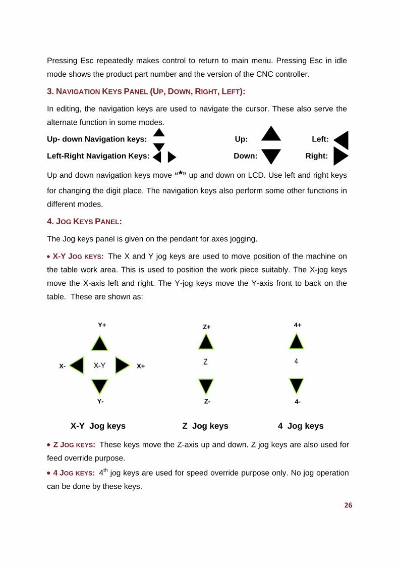
4. JOG KEYS PANEL:
The Jog keys panel is given on the pendant for axes jogging.
X-Y JOG KEYS: The X and Y jog keys are used to move position of the machine on
the table work area. This is used to position the work piece suitably. The X-jog keys
move the X-axis left and right. The Y-jog keys move the Y-axis front to back on the
table. These are shown as:
X-Y Jog keys Z Jog keys 4 Jog keys
Z JOG KEYS: These keys move the Z-axis up and down. Z jog keys are also used for
feed override purpose.
4 JOG KEYS: 4th jog keys are used for speed override purpose only. No jog operation
can be done by these keys.
Y-
X+ X-
Z- 4-
Y+ Z+ 4+
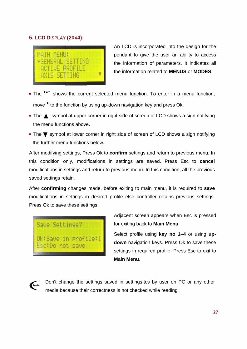
5. LCD
The
move
The
the m
The
the fu
After m
this co
modific
saved
After c
modific
Press O
D DISPLAY
‘*’ shows
e * to the f
symbo
menu funct
symbol
urther men
modifying s
ondition o
cations in s
settings re
confirming
cations in
Ok to save
Don't cha
media be
Y (20X4):
s the curre
function by
ol at upper
tions above
at lower c
nu functions
settings, Pr
only, modi
settings an
etain.
g changes
settings in
e these set
ange the s
cause thei
ent selecte
y using up-d
corner in r
e.
corner in ri
s below.
ress Ok to
ifications
nd return to
made, be
n desired
ttings.
settings sa
ir correctne
An LCD
pendant
the info
the infor
ed menu f
down navi
right side o
ight side o
confirm s
in setting
o previous
efore exitin
profile els
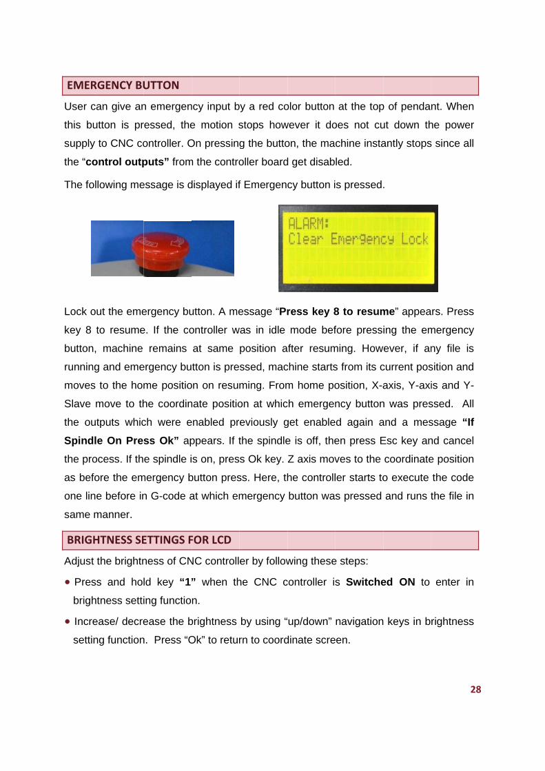
Adjacen
for exitin
Select p
down n
settings
Main M
aved in se
ess is not c
D is incorpo
t to give t
ormation o
rmation rel
function. T
gation key
of screen o
of screen o
settings an
s are sa
menu. In t
g to main
se controll
nt screen a
ng back to
profile usin
navigation
s in require
enu.
ettings.tcs
checked w
orated into
the user a
of paramet
lated to ME
To enter in
y and press
of LCD sho
of LCD sho
d return to
ved. Pres
this conditi
menu, it i
er retains
appears w
Main Men
ng key no
keys. Pres
ed profile.
by user o
while readin
o the desig
an ability t
ters. It ind
ENUS or M
n a menu
s Ok.
ows a sign
ows a sign
o previous
ss Esc to
on, all the
is required
previous
when Esc is
nu.
o 1–4 or u
ss Ok to sa
Press Esc
n PC or a
ng.
27
gn for the
to access
dicates all
MODES.
function,
notifying
notifying
menu. In
o cancel
previous
d to save
settings.
s pressed
using up-
ave these
to exit to
any other
7
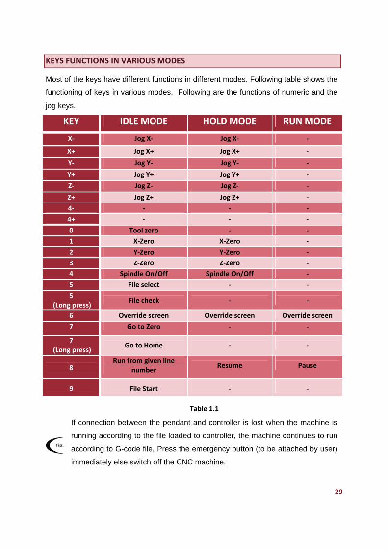
EMER
User c
this bu
supply
the “co
The fol
Lock o
key 8
button,
running
moves
Slave
the ou
Spindl
the pro
as befo
one lin
same m
BRIGH
Adjust
Pres
brigh
Incre
settin
RGENCY BU
an give an
utton is pr
to CNC co
ontrol outp
llowing me
ut the eme
to resume
, machine
g and eme
to the hom
move to th
tputs whic
le On Pres
ocess. If th
ore the em
e before in
manner.
HTNESS SE
the brightn
ss and hol
htness setti
ease/ decre
ng function
UTTON
n emergen
ressed, the
ontroller. O
puts” from
essage is d
ergency bu
e. If the co
remains
ergency bu
me positio
he coordin
ch were e
ss Ok” ap
e spindle i
mergency b
n G-code a
ETTINGS F
ness of CN
ld key “1”
ing functio
ease the b
n. Press “O
ncy input b
e motion s
On pressing
m the contro
displayed if
utton. A me
ontroller w
at same
tton is pre
on on resum
nate positio
enabled pr
ppears. If t
s on, pres
button pres
at which em
FOR LCD
NC controll
” when th
n.
brightness
Ok” to retur
by a red co
stops how
g the butto
oller board
f Emergenc
essage “Pr
was in idle
position a
ssed, mac
ming. From
on at whic
eviously g
the spindle
s Ok key.
ss. Here, th
mergency
er by follow
he CNC c
by using “
rn to coord
olor button
wever it do
on, the ma
d get disab
cy button i
ress key 8
mode bef
fter resum
chine starts
m home po
ch emergen
get enable
e is off, the
Z axis mov
he controll
button wa
wing these
controller is
up/down”
dinate scre
at the top
oes not cu
chine insta
led.
s pressed.
8 to resum
fore press
ming. How
s from its c
osition, X-a
ncy button
d again a
en press E
ves to the
ler starts to
s pressed
e steps:
s Switche
navigation
een.
p of penda
ut down th
antly stops
.
me” appea
ing the em
ever, if an
current pos
axis, Y-axi
n was pres
and a mes
Esc key an
coordinate
o execute
and runs t
ed ON to
keys in b
28
nt. When
he power
s since all
rs. Press
mergency
ny file is
sition and
is and Y-
ssed. All
ssage “If
nd cancel
e position
the code
the file in
enter in
rightness
8
29
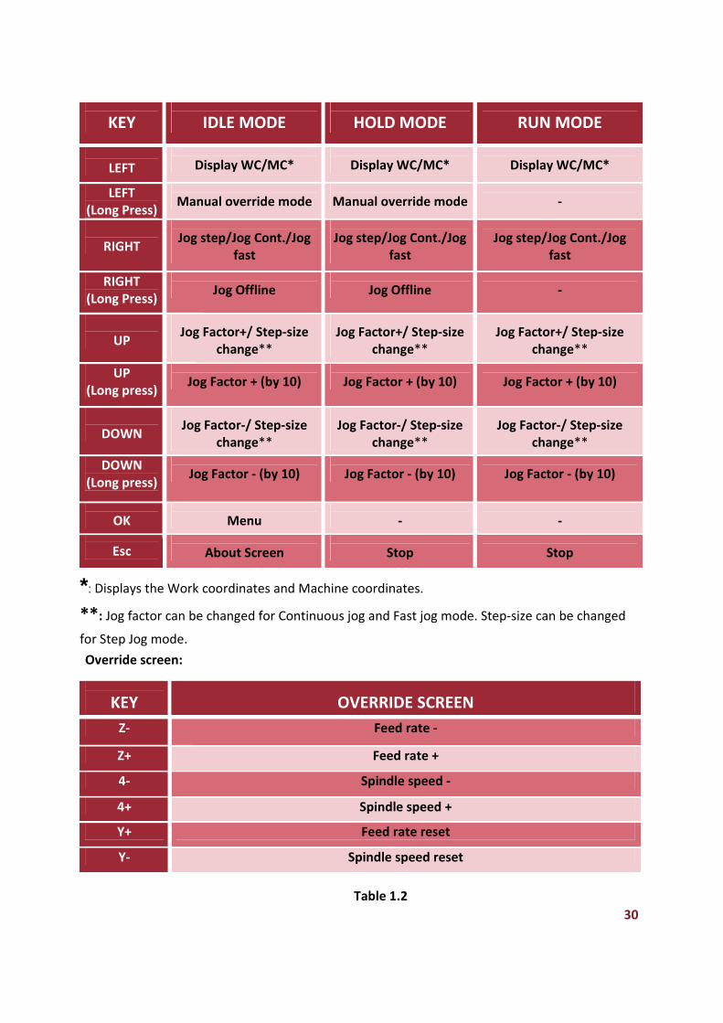
KEYS FUNCTIONS IN VARIOUS MODES
Most of the keys have different functions in different modes. Following table shows the
functioning of keys in various modes. Following are the functions of numeric and the
jog keys.
KEY IDLE MODE HOLD MODE RUN MODE
X‐ Jog X‐ Jog X‐ ‐
X+ Jog X+ Jog X+ ‐
Y‐ Jog Y‐ Jog Y‐ ‐
Y+ Jog Y+ Jog Y+ ‐
Z‐ Jog Z‐ Jog Z‐ ‐
Z+ Jog Z+ Jog Z+ ‐
4‐ ‐ ‐ ‐
4+ ‐ ‐ ‐
0 Tool zero ‐ ‐
1 X‐Zero X‐Zero ‐
2 Y‐Zero Y‐Zero ‐
3 Z‐Zero Z‐Zero ‐
4 Spindle On/Off Spindle On/Off ‐
5 File select ‐ ‐
5 (Long press)
File check
‐
‐
6 Override screen Override screen Override screen
7 Go to Zero ‐ ‐
7 (Long press)
Go to Home
‐
‐
8 Run from given line
number
Resume
Pause
9
File Start
‐
‐
Table 1.1
If connection between the pendant and controller is lost when the machine is
running according to the file loaded to controller, the machine continues to run
according to G-code file, Press the emergency button (to be attached by user)
immediately else switch off the CNC machine.
30
KEY
IDLE MODE
HOLD MODE
RUN MODE
LEFT
Display WC/MC*
Display WC/MC*
Display WC/MC*
LEFT (Long Press)
Manual override mode
Manual override mode
‐
RIGHT
Jog step/Jog Cont./Jog fast
Jog step/Jog Cont./Jog fast
Jog step/Jog Cont./Jog fast
RIGHT (Long Press)
Jog Offline
Jog Offline
‐
UP
Jog Factor+/ Step‐size change**
Jog Factor+/ Step‐size change**
Jog Factor+/ Step‐size change**
UP (Long press)
Jog Factor + (by 10)
Jog Factor + (by 10)
Jog Factor + (by 10)
DOWN
Jog Factor‐/ Step‐size change**
Jog Factor‐/ Step‐size change**
Jog Factor‐/ Step‐size change**
DOWN (Long press)
Jog Factor ‐ (by 10)
Jog Factor ‐ (by 10)
Jog Factor ‐ (by 10)
OK
Menu
‐
‐
Esc
About Screen
Stop
Stop
*: Displays the Work coordinates and Machine coordinates.
**: Jog factor can be changed for Continuous jog and Fast jog mode. Step‐size can be changed
for Step Jog mode.
Override screen:
KEY OVERRIDE SCREEN
Z‐ Feed rate ‐
Z+ Feed rate +
4‐ Spindle speed ‐
4+ Spindle speed +
Y+ Feed rate reset
Y‐ Spindle speed reset
Table 1.2

31
CNC CONTROLLER BOARD CONNECTIONS WITH PENDANT
The controller makes communication with pendant through RS-232 serial port. There
are two serial communication channels on the CNC controller board. One dedicated
Serial communication channel is made between the hand held pendant and the CNC
control board while the other channel can be made between the Controller board and
any peripheral. Both serial ports of controller board can work on the same time.
Each pendant is shipped with an already connected serial cable. Connection between
CNC control board and pendant is made through an on-board DB-9 (F) connector and
a DB-9 (M) connected at other end of serial cable. If the communication between the
Pendant and the CNC controller board lost, a message “Controller disconnected”
appears on the LCD. When the connection resolves back, LCD shows the coordinate
screen.
Notes: Some points to be kept in mind while using serial communications:
1. Operators should avoid installing serial cable next to high voltage lines and prevent
any foot traffic from occurring over or across the serial cables.
2. The serial cable should not be involved in circumstances where damage is probable
and operation over wire shouldn't exceed wire temperature beyond 100 degree
Celsius.
3. The serial cable should not be operated next to high voltage or fluorescent lights
which leads to error in data transmission between serial port and pendant.
4. The cable should be checked not to be cut or damaged.
5. There should not be loose connections else leads to poor transmission quality and
difficulties in transmissions.
Don't operate the controller or the pendant with wet hands. Be sure about the
connection of pendant with dedicated connector on the CNC Controller board.
Take care that pendant should not be dropped. The LCD can be damaged due
to the external mechanical strokes. Handle the pendant carefully.
Default values are stored in on chip ROM of every controller and it can't be
altered by user.
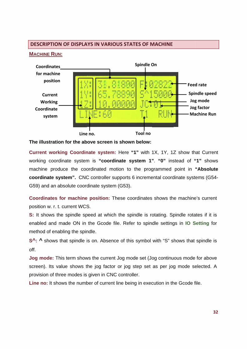
DESCR
MACHI
The ill
Curren
working
machin
coordi
G59) a
Coord
position
S: It s
enable
method
S^: ^
off.
Jog m
screen
provisio
Line n
C
W
Coor
Coo
for m
RIPTION O
INE RUN:
ustration
nt working
g coordina
ne produc
inate syst
and an abs
inates for
n w. r. t. cu
hows the
ed and ma
d of enabli
shows tha
ode: This
). Its value
on of three
o: It shows
Current
Working
rdinate
system
ordinates
machine
position
OF DISPLA
for the ab
g Coordin
ate system
ce the coo
em”. CNC
olute coord
r machine
urrent WCS
spindle sp
ade ON in
ng the spin
at spindle i
term show
e shows t
e modes is
s the numb
Line
AYS IN VAR
bove scree
nate syste
m is “coo
ordinated
C controlle
dinate syst
e position
S.
peed at wh
the Gcod
ndle.
is on. Abs
ws the curr
the jog fac
given in C
ber of curre
e no.
RIOUS STA
en is show
em: Here
ordinate s
motion to
er supports
tem (G53)
: These co
hich the sp
e file. Ref
ence of th
rent Jog mo
ctor or jog
CNC contro
ent line be
ATES OF M
wn below:
“1” with
system 1”
o the prog
s 6 increme
.
oordinates
pindle is ro
fer to spin
is symbol
ode set (Jo
step set
oller.
ing in exec
Tool no
Spindle O
MACHINE
1X, 1Y, 1Z
”. “0” ins
grammed
ental coord
s shows th
otating. Sp
dle setting
with “S” s
og continu
as per jog
cution in th
On
Z show th
stead of “
point in “
dinate syste
e machine
pindle rota
gs in IO S
hows that
ous mode
g mode se
he Gcode f
Spin
Ma
Jog
Jog
Feed
32
hat Current
“1” shows
“Absolute
ems (G54-
e’s current
ates if it is
Setting for
spindle is
for above
elected. A
file.
ndle speed
achine Run
g factor
g mode
d rate
2
t
s
e
-
Tool n
provisio
selectin
F: F sta
Machin
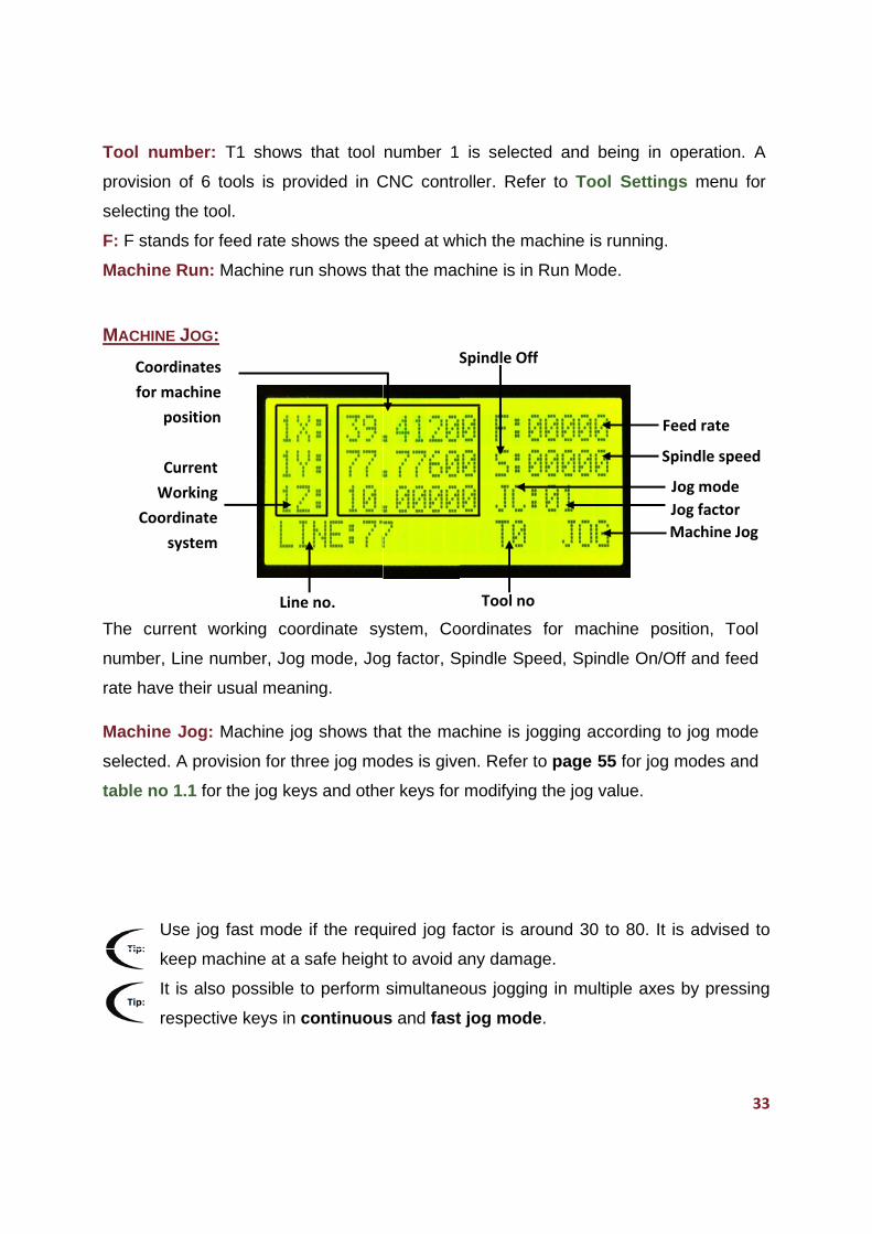
MACHI
The cu
numbe
rate ha
Machin
selecte
table n
Co
Co
for
number: T
on of 6 to
ng the tool
ands for fe
ne Run: M
INE JOG:
urrent wo
er, Line num
ave their us
ne Jog: M
ed. A provis
no 1.1 for t
Use jog f
keep mac
It is also
respective
Current
Working
oordinate
system
ordinates
r machine
position
T1 shows
ools is pro
.
eed rate sh
Machine run
rking coo
mber, Jog
sual meani
Machine jog
sion for thr
the jog key
fast mode
chine at a s
possible to
e keys in c
Line
that tool
vided in C
hows the sp
n shows th
rdinate sy
mode, Jog
ing.
g shows th
ree jog mo
ys and othe
if the requ
safe heigh
o perform
continuou
e no.
number 1
CNC contro
peed at wh
hat the mac
ystem, Co
g factor, S
hat the ma
odes is give
er keys for
uired jog fa
t to avoid a
simultaneo
s and fast
S
is selecte
oller. Refe
hich the ma
chine is in
oordinates
Spindle Spe
achine is jo
en. Refer t
modifying
actor is aro
any damag
ous joggin
t jog mode
Tool no
Spindle Off
ed and be
er to Tool
achine is r
Run Mode
for mach
eed, Spind
ogging acc
to page 55
the jog va
ound 30 to
ge.
ng in multip
e.
f
eing in ope
Settings
unning.
e.
hine positi
dle On/Off
cording to j
5 for jog mo
alue.
o 80. It is
ple axes b
Spin
Ma
Jog
Jog
Feed
33
eration. A
menu for
on, Tool
and feed
og mode
odes and
advised to
y pressing
ndle speed
achine Jog
g factor
g mode
d rate
3
o
g
MACHI
The C
numbe
rate ha
Machin
MACHI
The C
numbe
rate ha
Machin
C
W
Coor
s
C
W
Coor
s
Coor
for m
p
Coor
for m
p
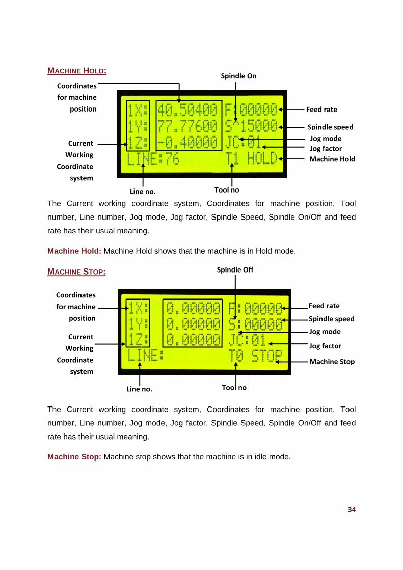
INE HOLD:
Current wo
er, Line nu
as their usu
ne Hold: M
INE STOP:
Current wo
er, Line nu
as their usu
ne Stop: M
Current
Working
rdinate
system
Current
Working
rdinate
system
rdinates
machine
position
rdinates
machine
position
orking coo
mber, Jog
ual meanin
Machine H
orking coo
mber, Jog
ual meanin
Machine st
Line
Line
ordinate s
g mode, Jo
ng.
old shows
ordinate s
g mode, Jo
ng.
top shows
no.
e no.
system, C
og factor, S
that the m
system, C
og factor, S
that the m
oordinates
Spindle Sp
machine is i
oordinates
Spindle Sp
achine is i
Tool no
Tool no
Spindle O
Spindle O
s for mac
peed, Spin
in Hold mo
s for mac
peed, Spin
n idle mod
On
Off
chine posi
ndle On/Of
ode.
chine posi
ndle On/Of
de.
Spi
Ma
Jog
Jog
Spin
Ma
Jog
Jog
Feed
Fee
34
ition, Too
ff and feed
ition, Too
ff and feed
ndle speed
achine Stop
g factor
g mode
ndle speed
achine Hold
g factor
g mode
d rate
ed rate
4
l
d
l
d
p
d
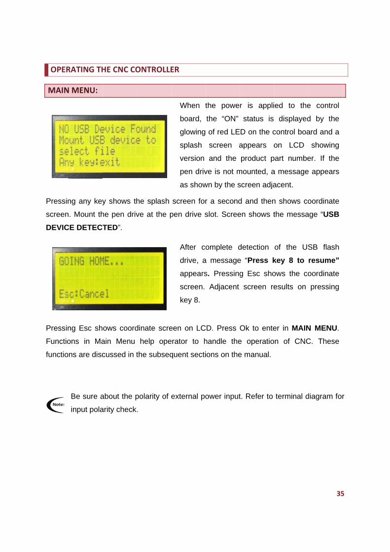
OPER
MAIN
Pressin
screen
DEVIC
Pressin
Functio
functio
RATING TH
N MENU:
ng any key
. Mount th
CE DETECT
ng Esc sh
ons in Ma
ns are disc
Be sure a
input pola
HE CNC CO
y shows th
he pen driv
TED”.
ows coord
ain Menu
cussed in t
about the p
arity check.
ONTROLLE
he splash
ve at the p
dinate scre
help ope
the subseq
polarity of e
.
ER
When t
board,
glowing
splash
version
pen driv
as show
screen for
pen drive s
After co
drive, a
appears
screen.
key 8.
een on LC
erator to h
quent secti
external po
the powe
the “ON”
of red LE
screen a
and the
ve is not m
wn by the s
r a second
slot. Scree
omplete d
a message
s. Pressing
Adjacent
D. Press O
handle the
ions on the
ower input
r is appli
status is
D on the c
appears o
product p
mounted, a
screen adja
d and then
en shows t
detection
e “Press k
g Esc sho
screen re
Ok to ente
e operatio
e manual.
t. Refer to
ed to the
displayed
control boa
on LCD
part numbe
a message
acent.
n shows co
the messa
of the US
key 8 to
ows the co
esults on
er in MAIN
n of CNC
terminal d
35
e control
d by the
ard and a
showing
er. If the
e appears
oordinate
age “USB
SB flash
resume”
oordinate
pressing
N MENU.
C. These
diagram for
5
r
36
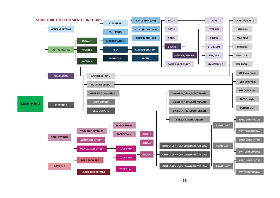
STRUCTURE TREE FOR MENU FUNCTIONS
MAIN MENU
GENERAL SETTING
ACTIVE PROFILE
AXIS SETTING
IO SETTING
TOOL SETTINGS
DATA FILE
STEP PULSE
PATH MODE
MAX DEVIATION
HELP
DIAGNOSIS
DEFAULT
PROFILE 1
PROFILE 4
EXACT STOP (G61)
CONTINUOUS (G64)
BLOCK MODE (G70)
KEYPAD FUNCTION
ABOUT
X‐AXIS
Y‐AXIS
Z‐AXIS
Z‐INHIBIT
DISABLE/ ENABLE
DRIVE
STEP PIN
DIR PIN
STEPS/MM
MM/MIN
(MM/MIN)^2SAME AS FOR X‐AXIS
ENABLE/DISABLE
STEP PIN
MAX RPM
MIN RPM
DWELL SEC
STEP FREQHz
SPINDLE SETTING
HOMING SETTING
HOME SWITCH SETTING
LIMIT SETTING
MISC OUTPUTS
TOOL ZERO SETTINGS
AUTO TOOL OFFSET
MANUAL EDIT OFFSET
SENSOR HTmm
BACKOFF mm TOOL 1
TOOL 2
TOOL 6
TOOL 1 mm
TOOL 2 mm
TOOL 6 mm
LOAD FROM FILE
LOAD FROM DEFAULT
X‐AXIS EN/HIGH/LOW/DISABLE
Y‐AXIS EN/HIGH/LOW/DISABLE
Y‐SLAVE ENABLE/DISABLE
Z‐AXIS EN/HIGH/LOW/DISABLE
OUTPUT1 EN HI/EN LOW/DIS HI/DIS LOW
OUTPUT2 EN HI/EN LOW/DIS HI/DIS LOW
OUTPUT6 EN HI/EN LOW/DIS HI/DIS LOW
X‐AXIS LIMIT
Y‐AXIS LIMIT
Z‐AXIS LIMIT
HARD LIMIT EN/DIS
HARD LIMIT EN/DIS
HARD LIMIT EN/DIS
SWITCH HIGH/LOW
SWITCH HIGH/LOW
SWITCH HIGH/LOW
SEEK (mm/min)
FEED (mm/min)
PULLOFF mm
SAFE Z‐Height
DEBOUNCE ms
37
GENERAL SETTINGS
The GENERAL SETTINGS function adjusts Step pulse width, Path mode & Max
deviate. Keypad function shows the function of all the keys on pendant in various
modes. Diagnosis function allows the operator to diagnose inputs and outputs of the
CNC controller.
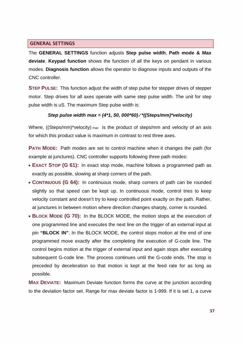
STEP PULSE: This function adjust the width of step pulse for stepper drives of stepper
motor. Step drives for all axes operate with same step pulse width. The unit for step
pulse width is uS. The maximum Step pulse width is:
Step pulse width max = (4*1, 50, 000*60) ⁄ *((Steps/mm)*velocity)
Where, ((Steps/mm)*velocity) max is the product of steps/mm and velocity of an axis
for which this product value is maximum in contrast to rest three axes.
PATH MODE: Path modes are set to control machine when it changes the path (for
example at junctures). CNC controller supports following three path modes:
EXACT STOP (G 61): In exact stop mode, machine follows a programmed path as
exactly as possible, slowing at sharp corners of the path.
CONTINUOUS (G 64): In continuous mode, sharp corners of path can be rounded
slightly so that speed can be kept up. In continuous mode, control tries to keep
velocity constant and doesn’t try to keep controlled point exactly on the path. Rather,
at junctures in between motion where direction changes sharply, corner is rounded.
BLOCK MODE (G 70): In the BLOCK MODE, the motion stops at the execution of
one programmed line and executes the next line on the trigger of an external input at
pin “BLOCK IN”. In the BLOCK MODE, the control stops motion at the end of one
programmed move exactly after the completing the execution of G-code line. The
control begins motion at the trigger of external input and again stops after executing
subsequent G-code line. The process continues until the G-code ends. The stop is
preceded by deceleration so that motion is kept at the feed rate for as long as
possible.
MAX DEVIATE: Maximum Deviate function forms the curve at the junction according
to the deviation factor set. Range for max deviate factor is 1-999. If it is set 1, a curve
is form
max de
HELP:
below:
ABO
KEYP
various
functio
mode i
DIAGN
functio
Metho
1. Ente
2. Ente
Metho
Metho
med with th
eviate, grea
screen sh
UT: 'ABO
PAD FUNC
s modes of
n of all ke
s discusse
OSIS FUN
ning of inp
d to acces
er in MAIN
er in "Gene
d to acces
d to acces
he deviatio
ater is the
hows the K
UT' screen
CTION: 'KE
f CNC con
eys in a pa
ed in Key F
NCTION: D
puts and ou
ss GENER
MENU.
eral setting
ss STEP P
ss PATH M
on of 0.01
distance o
Keypad fun
n shows pr
EYPAD FU
troller. Th
articular mo
Functions
iagnosis f
utputs of th
RAL SETT
gs".
PULSE:
MODE:
E
mm from
of curve fro
nction and
roduct part
UNCTION'
he keypad f
ode. The f
in variou
function m
he CNC co
INGS is fo
a. Enter in
b. Edit th
confirm o
previous m
EXACT STO
a. Select a
screen ap
b. Select
to exit to p
the junctio
om the junc
about fun
t number a
screen sh
function al
function of
s Modes.
makes the
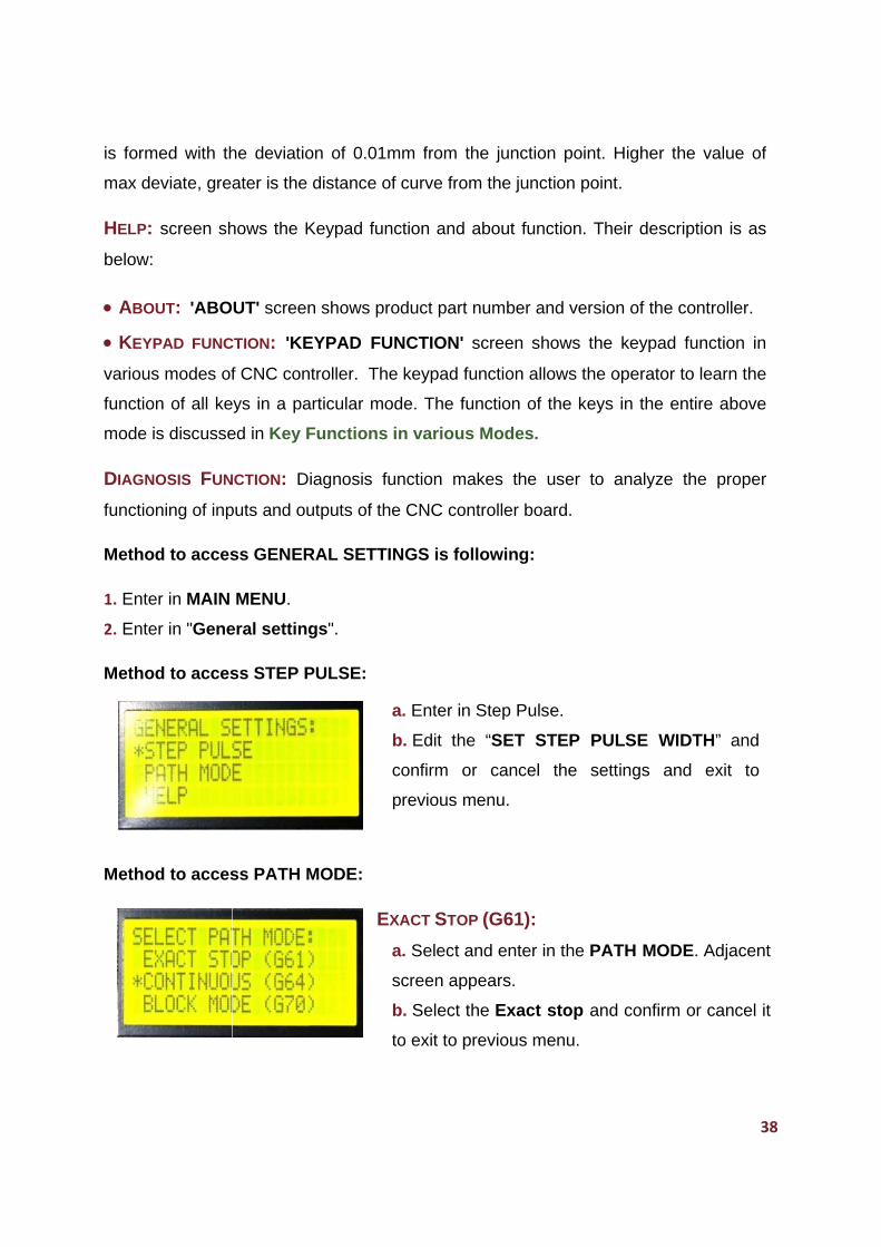
ontroller bo
ollowing:
n Step Puls
he “SET S
or cancel
menu.
OP (G61):
and enter
ppears.
the Exact
previous m
on point. H
ction point.
nction. The
and version
hows the
lows the o
the keys
user to a
oard.
se.
STEP PUL
the setti
in the PAT
stop and
menu.
Higher the
.
eir descript
n of the co
keypad fu
operator to
in the enti
analyze th
LSE WIDT
ings and
TH MODE.
confirm or
38
value of
tion is as
ntroller.
unction in
learn the
re above
e proper
TH” and
exit to
. Adjacent
r cancel it
8
CONTIN
a. Ente
b. Con
BLOCK
a. Ente
b. Con
Metho
a. Ente
b. Edit
previou
Metho
Refer t
Metho
a. Sele
the pro
b. Pres
3. Save
D
Metho
INPUT
corresp
NUOUS MO
er in path m
firm or can
K MODE (G
er in path m
firm or can
d to acces
er in Max d
the Max
us menu.
d to acces
to table no
d to acces
ect the abo
oduct part n
ss Esc to e
e the confi
Don't chan
d to acces
T ANALYS
ponding in
ODE (G64)
mode and s
ncel it and
G70):
mode and s
ncel it and
ss Max De
deviate.
DEVIATE
ss HELP m
o 1.1 and ta
ss HELP m
out function
number an
exit to prev
rmed settin
nge the nam
ss Diagno
SIS: When
put name o
):
select Con
exit to pre
select Bloc
exit to pre
eviate men
FACTOR
menu>>Ke
able no 1.
menu>> A
n in HELP
nd the vers
vious menu
ngs in requ
me of the f
osis menu
any input
on the LCD
ntinuous.
vious men
ck mode.
vious men
nu:
R and conf
eypad men
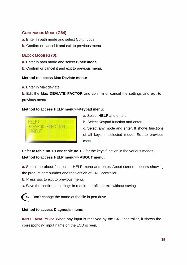
a. Select
b. Select
c. Select
of all key
menu.
2 for the k
ABOUT me
P menu and
sion of CNC
u.
uired profile
file in pen d
:
is receive
D screen.
nu.
nu.
firm or can
nu:
HELP and
Keypad fu
any mode
ys in sele
keys functio
enu:
d enter. Ab
C controlle
e or exit w
drive.
ed by the C
ncel the se
d enter.
nction and
and enter
ected mode
on in the va
bout scree
r.
without savi
CNC contr
ettings and
d enter.
r. It shows
e. Exit to
arious mod
en appears
ng.
roller, it sh
39
d exit to
functions
previous
des.
s showing
hows the
9
40
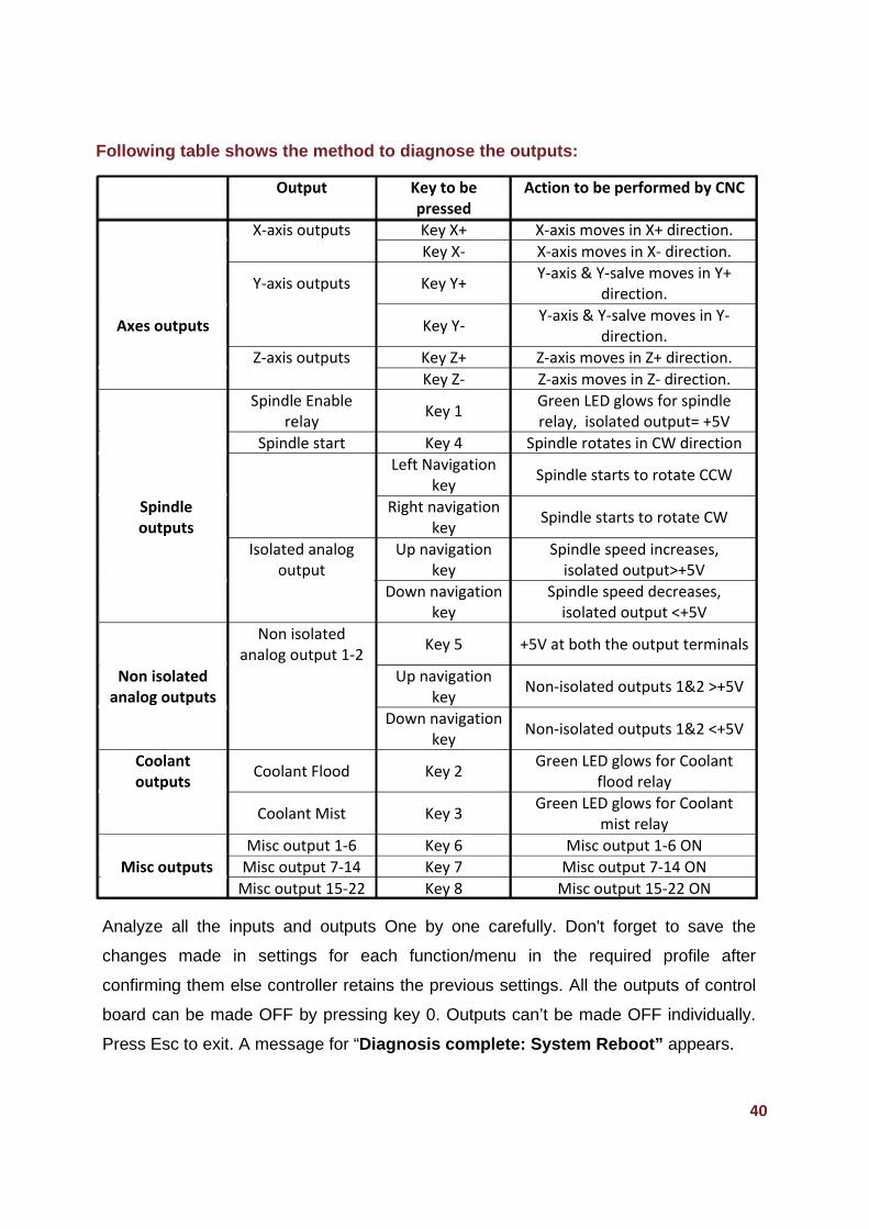
Following table shows the method to diagnose the outputs:
Analyze all the inputs and outputs One by one carefully. Don't forget to save the
changes made in settings for each function/menu in the required profile after
confirming them else controller retains the previous settings. All the outputs of control
board can be made OFF by pressing key 0. Outputs can’t be made OFF individually.
Press Esc to exit. A message for “Diagnosis complete: System Reboot” appears.
Output Key to be pressed
Action to be performed by CNC
X‐axis outputs Key X+ X‐axis moves in X+ direction.
Key X‐ X‐axis moves in X‐ direction.
Y‐axis outputs
Key Y+ Y‐axis & Y‐salve moves in Y+
direction.
Axes outputs
Key Y‐ Y‐axis & Y‐salve moves in Y‐
direction.
Z‐axis outputs Key Z+ Z‐axis moves in Z+ direction.
Key Z‐ Z‐axis moves in Z‐ direction.
Spindle Enable relay
Key 1 Green LED glows for spindle relay, isolated output= +5V
Spindle start Key 4 Spindle rotates in CW direction
Left Navigation key
Spindle starts to rotate CCW
Spindle outputs
Right navigation key
Spindle starts to rotate CW
Isolated analog output
Up navigation key
Spindle speed increases, isolated output>+5V
Down navigation key
Spindle speed decreases, isolated output <+5V
Non isolated analog output 1‐2
Key 5
+5V at both the output terminals
Non isolated analog outputs
Up navigation key
Non‐isolated outputs 1&2 >+5V
Down navigation key
Non‐isolated outputs 1&2 <+5V
Coolant outputs
Coolant Flood
Key 2 Green LED glows for Coolant
flood relay
Coolant Mist
Key 3 Green LED glows for Coolant
mist relay
Misc output 1‐6 Key 6 Misc output 1‐6 ON
Misc outputs Misc output 7‐14 Key 7 Misc output 7‐14 ON
Misc output 15‐22 Key 8 Misc output 15‐22 ON
ACTIV
ACTIV
setting
operati
“setting
A prov
default
no para
Setting
the pro
All the
shipme
Metho
AXIS S
AXIS
parame
which
orthogo
For AX
save th
FOR X
parame
VE PROFIL
VE PROFIL
s, Axis se
ion to be c
gs.tcs” stor
vision for f
t profile is
ameters ar
gs.tcs is a
ofile. These
default se
ent and can
d to acces
SETTINGS
SETTINGS
eters in pro
produces
onal direct
XIS SETTI
hem in des
X-AXIS, Y-A
eters. Mak
E
LE menu m
ettings, IO
controlled b
red in pen
four user
given. All
re changed
user creat
e settings c
ettings are
n’t be alter
ss ACTIVE
S menu f
ofiles. CNC
relative
tions called
NGS, mak
sired profile
AXIS AND Z
ke the settin
make the o
O settings
by CNC Co
drive to th
programm
user progr
d in them.
ted file in
can be load
e stored in
red or no o
E PROFILE
functions m
C controlle
linear mo
d X, Y and
ke changes
e.
Z-AXIS: T
ngs for all
operator to
for spind
ontroller. T
e active pr
mable profi
rammable
USB Flash
ded to all t
n on-chip R
other settin
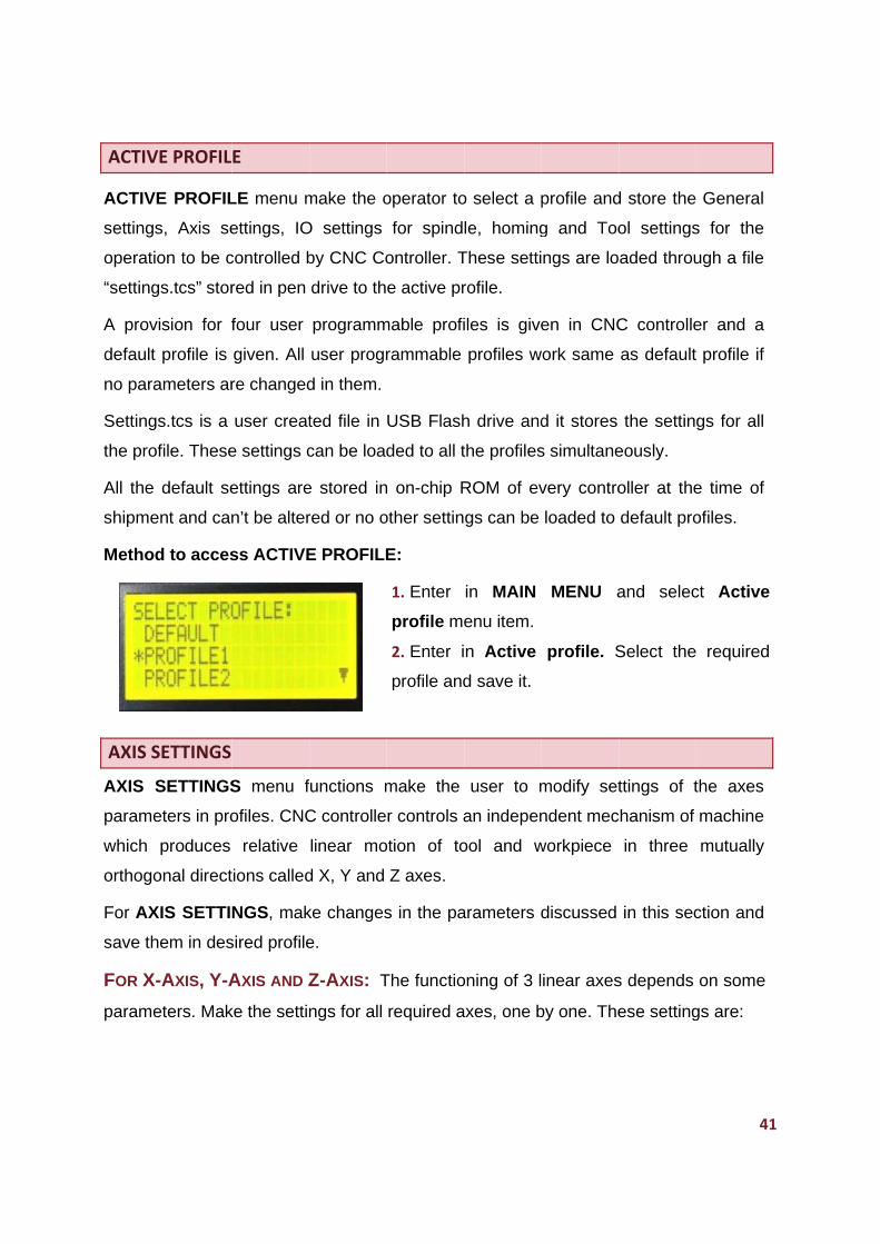
E:
1. Enter
profile me
2. Enter i
profile and
make the
r controls a
otion of to
Z axes.
s in the pa
The functio
required a
o select a p
le, homing
These setti
rofile.
iles is give
profiles w
h drive and
the profiles
ROM of ev
gs can be
in MAIN
enu item.
n Active
d save it.
user to m
an indepen
ool and w
arameters d
oning of 3 l
axes, one b
profile and
g and Too
ngs are lo
en in CNC
work same
d it stores
s simultane
very contro
loaded to
MENU a
profile. S
modify set
ndent mec
workpiece
discussed
inear axes
by one. The
d store the
ol settings
aded throu
C controlle
as default
the settin
eously.
oller at the
default pro
and selec
Select the
ttings of t
chanism of
in three
in this sec
s depends
ese setting
41
General
s for the
ugh a file
er and a
profile if
gs for all
e time of
ofiles.
ct Active
required
the axes
machine
mutually
ction and
on some
gs are:
1
42
DRIVE: ENABLE/DISABLE: ENABLE/DISABLE is for enabling or disabling the axis
drive. The drive mechanics of CNC machines convert torque provided by the electric
motors into linear motion of the tool head. Step and Dir outputs are disabled for the
axis whose drive has been disabled.
STEP PIN: LOW/HIGH: The STEP PIN selects the state of the step pulse given to
drive of stepper motor (connected to axes). All axes have their dedicated Step output
pins on the control board; however step pulse width is same for all the axes. When this
pin is active high, an active high step pulse is driven to respective axis drive. When the
pin is active low, an active low step pulse is driven to the axis drive.
DIR PIN: LOW/HIGH: The DIR PIN selects the state of direction signal given to the
drive of motor attached to axis. All axes have their dedicated Direction output pins on
the control board and axes can have different direction settings according to the job to
be performed. When this pin is active high, the machine/tool head moves in positive or
negative direction according to the commands given in G-code file or by jog keys.
And when pin is active low, machine/tool head moves in the opposite direction to one
in active high state. The direction for X axis on the work bed of the machine can be
either left or right, for Y axis is Back or Front whereas for Z axis is either up or down.
STEP/MM: STEPS/MM shows number of steps, the motor must turn in order for the
CNC machine to move 1 mm on the particular axis. This is machine dependent and
remains same for a particular axis of machine. Different machines can have different
values of steps/mm. The axes of the machine can have different “step/mm” number.
MM/MIN: It shows the maximum velocity of the axis. Different axes can have
different velocities. The maximum achievable velocity for all axes is:
Velocity (max) = (1, 50, 000*60) ⁄ (Steps ⁄mm)
Steps/mm remains fixed for axis. The pulse rate varies in accordance with velocity
(MM/MIN) for particular axis. Maximum achievable pulse rate for all axes is 150 KHz.
MM/SEC²: It is the increment of processing velocity from initial velocity to highest
one for motor connected to axis. The value of the acceleration is user programmable
and can vary for all axes. The range of acceleration for all axes is 1 to 99999.
Set all these parameters for all the axes, individually.
Z-INH
axis do
axis mo
Follow
Metho
h. Con
i. Modi
FOR Z
3. Save
IBIT ENAB
oes not mo
otion in G-
ing is disc
d to acces
firm or can
fy Axes Se
Z INHIBIT:
e the confi
BLE/DISAB
ove if Z-inh
-code file d
ussed the w
ss Axis se
ncel the mo
ettings for
rmed settin
BLE: Z-inh
hibit functio
does not wo
way to acc
ettings>> X
odifications
rest 3 axes
ngs in requ
hibit functio
on is set en
ork of Z inh
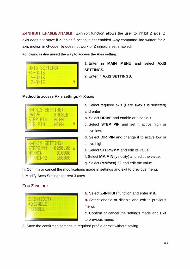
cess the Ax
1. Enter
SETTING
2. Enter in
X-axis:
a. Select
and enter
b. Select
c. Select
active low
d. Select
active hig
e. Select S
f. Select M
g. Select
s made in
s.
a. Select
b. Select
menu.
c. Confirm
to previou
uired profil
on allows
nabled. An
hibit is set
xis setting:
in MAIN
GS.
n AXIS SE
required a
r.
DRIVE an
STEP PI
w.
DIR PIN a
h.
STEPS/MM
MM/MIN (v
(MM/sec)
settings an
Z-INHIBIT
enable or
m or cance
us menu.
e or exit w
the user
ny comman
enabled.
:
MENU
ETTINGS.
axis (Here
d enable o
N and se
and chang
M and edit
velocity) an
^2 and ed
nd exit to p
T function a
r disable a
el the setti
without savi
to inhibit Z
nd line writ
and sele
X-axis is
or disable it
et it active
e it to acti
t its value.
nd edit the
dit the value
previous m
and enter i
and exit to
ings made
ing.
43
Z axis. Z
tten for Z
ect AXIS
selected)
t.
e high or
ive low or
value.
e.
menu.
n it.
o previous
e and Exit
3
44
IO SETTING
IO setting provides an interface between CNC Controller and CNC machine by making
settings for limit and home inputs and for spindle outputs. These settings make
settings for home and limit switches and also for buffered Misc outputs. The functions
under IO setting menu are discussed below:
SPINDLE SETTING
Spindle holds the cutting tool. Spindle can rotate in CW/CCW direction with velocity
set in Gcode file. The axis of spindle is kept parallel to Z-axis and is coincident with Z-
axis; except in machines where spindle can be rotated by rotational axis. The
functions for spindle settings decides Spindle Enable/Disable, Step frequency for
spindle drive and state of step pulse, maximum revolution per minute at which spindle
needs to spin. These are given below:
SPINDLE (ENABLE/DISABLE): The Spindle Enable/Disable function allows operator
to enable or disable spindle by giving respective signal to spindle drive. Spindle
rotates if spindle drive receives enable signal and spindle is made ON in Gcode file. If
spindle is disabled in IO setting and spindle is made ON in G-code file, then spindle
does not work. “Spindle enable/disable” is the relay output from CNC Control Board
and the relay remains off is spindle is disabled.
STEP PIN HIGH/LOW: It sets state of the step pulse driven to spindle drive. This pin,
if selected active high, drives an active high pulse and if active low, drives an active
low signal to spindle drive. This output pin get disabled if Spindle is set disabled.
MAX RPM: The Max RPM refers to maximum number of revolutions per minute
spindle rotates. Spindle can be set to rotate at or below the maximum velocity set but
not beyond Max RPM.
MIN RPM: The Min RPM refers to minimum number of revolutions per minute
spindle rotates. Spindle can be set to rotate at or above the minimum velocity set but
not below Min RPM.
DWELL SEC: Some delay is set before the spindle starts to rotate and at time when
spindle stops after rotation. This delay is dwell time. Spindle remains idle for this
duration of time. It is a user programmable and is in seconds.
STEP
control
and is
Metho
1. Sele
Metho
g. Sele
h. Con
HOM
HOMIN
configu
machin
such c
home s
For ho
zero. In
In seco
trigger
proxim
to prec
last cyc
P FREQ H
ler board.
user progr
d to acces
ect and ent
d to acces
ect STEP F
nfirm or can
MING SETT
NG SETTI
urable opti
ne. Homing
case, mach
switches s
ming, CNC
n first cycle
ond cycle,
their home
ity of all ho
cisely “hom
cle, machi
HZ: It dec
By defaul
rammable.
Step
ss IO Sett
er in IO SE
ss Spindle
FREQ and
ncel the se
TING
ING provid
ons to ret
g can be d
hine should
hould be in
C controlle
e, Z-axis m
rest two a
e switches
ome switch
me” at the
ine moves
ides frequ
t, it is 1 K
freq (max)
ing:
ETTING fu
e Setting:
modify the
ettings mad
des settin
turn to hom
done in con
d be place
nstalled for
er follows a
moves upw
axes and Y
s. In both c
hes, machi
e machine
to a posit
uency of s
Hz and ma
x) = (1MHz)
unction in M
a. Select
b. Set the
c. Select
d. Select
e. Select
f. Select D
e values.
de and Exi
gs for an
me positio
nditions wh
ed somewh
r all axes o
a sequence
ward till find
Y-slave m
cycles, the
ine leaves
zero locat
tion determ
step pulse
aximum is
z) ⁄ (2 * Puls
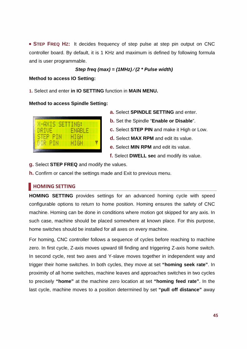
MAIN MEN
SPINDLE
e Spindle “
STEP PIN
MAX RPM
MIN RPM
DWELL se
t to previou
n advance
n. Homing
here motio
here at kn
on every m
e of cycles
ding and tr
oves toget
ey move at
and appro
tion at set
mined by s
at step p
defined b
lse width)
NU.
SETTING
Enable or
N and make
M and edit
and edit it
ec and mod
us menu.
d homing
g ensures
on got skipp
own place
machine.
s before re
riggering Z
ther in ind
t set “hom
oaches swi
t “homing
set “pull o
pin output
by following
and enter
r Disable”.
e it High or
its value.
ts value.
dify its valu
cycle wit
the safety
ped for an
e. For this
eaching to
Z-axis hom
dependent
ming seek
itches in tw
feed rate
off distanc
45
on CNC
g formula
r.
r Low.
ue.
th speed
y of CNC
y axis. In
purpose,
machine
me switch.
way and
rate”. In
wo cycles
e”. In the
ce” away
5
from m
rate. Fi
SEEK
Home
program
FEED
to prec
program
PULL
for all e
position
program
SAFE
switch
Z-axis
By this
axis of
DEBO
presse
of debo
Here is
g. Con
machine ze
inally mach
K (MM/MIN)
switch o
mmable an
D (MM/MIN)
cisely hom
mmable an
L OFF MM:
enabled ax
n from m
mmable an
E Z- HEIGH
for Z-axis
uplifts to a
s, tool insta
machine.
OUNCE m
ed. By defa
ounce dela
s the meth
firm or can
ero location
hine stops
): The rat
n pressing
nd range fo
): The rate
e at mach
nd maximu
The mac
xes in coor
machine ze
nd maximu
HT: This
either has
a height se
alled at Z-a
S: This
ault, it is 10
ay is 1 seco
hod to acc
ncel the se
n for all e
, where DR
te at which
g Key 7
or seek rat
e at which
hine zero lo
um range f
chine move
rdinated w
ero is se
um range is
function e
been disa
t in this fun
axis remain
is delay s
00 ms. Ho
ond. The u
cess HOM
ettings mad
nabled axe
RO shows
h an axis t
long is c
te is 1-999
home swit
ocation is
for feed rat
es to a pos
way at seek
et by “Pu
s size of m
nsures sa
abled or no
nction and
ns safe. Th
settled for
owever; it i
units for de
ING SETT
a. Select a
b. Select
c. Select
d. Select
e. Select S
f. Select D
de and Exit
es in coor
current kn
raverses f
called hom
9mm/min.
tches are t
called hom
te is 9999 m
sition away
k rate after
ull off” fu
machine.
fety of CN
ot installed.
then hom
he maximu
r debounc
is user pro
ebounce de
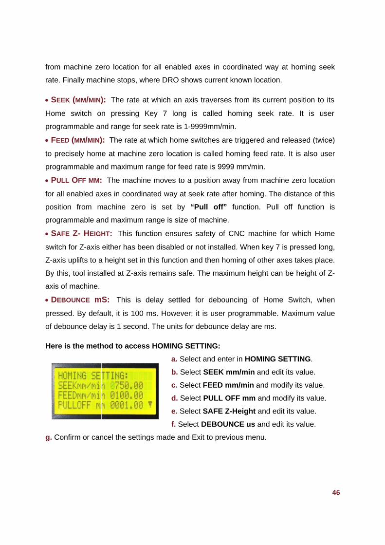
TING:
and enter
SEEK mm
FEED mm
PULL OFF
SAFE Z-H
DEBOUNC
t to previou
rdinated w
nown locati
from its cu
ming seek
riggered a
ming feed
mm/min.
y from ma
r homing. T
unction. P
NC machin
. When key
ing of othe
um height
cing of Ho
ogrammab
elay are ms
in HOMING
m/min and
m/min and
F mm and
Height and
CE us and
us menu.
ay at hom
ion.
rrent posit
k rate. It
nd release
rate. It is a
chine zero
The distanc
Pull off fun
ne for whic
y 7 is press
er axes tak
can be he
ome Switc
le. Maximu
s.
G SETTIN
edit its val
modify its
modify its
edit its va
edit its val
46
ming seek
tion to its
is user
ed (twice)
also user
o location
ce of this
nction is
ch Home
sed long,
kes place.
ight of Z-
ch, when
um value
G.
lue.
value.
value.
lue.
lue.
6
47
HOME SWITCH SETTING
Home Switch Setting allows the operator to enable or disable home switches for all
axes. Disable the home switches for axes for which switches are not installed. An
input signal is driven from home switch to its axis Home-In terminal on CNC control
board when it got triggered.
When CNC machine is in Run/Jog mode and Home switch for an axis got triggered,
an input pulse is generated to axis Home-IN pin and motion of entire axes system
ceases. A message of alarm for Hard Home/Limit is dispalyed on screen. Press Ok
key to continue. None of jog key works and motion for entire system stops in this
condition. Press left navigation key long to enter in manual override mode and to
release the switch.
All the keys are disbaled except jog and navigation keys in manual override mode. Jog
the machine reverse using jog keys to release switch and set machine at required
position. At any situation, if limit/ home switch got triggered, hard limit/home is not
checked and user need to jog machine reverse. Press left navigation key long again to
exit from manual override mode.
For all axes, it is required to make some settings for home switches. These are:
FOR X, Y AND Z AXIS:
ENABLE: sets the home switch enabled for the axis. It makes the homing of the axis
when key 7 is pressed long.
HIGH/ LOW: Active high sets home switch to generate an active low pulse to axis
Home-In terminal on the board when switch got triggered.
Active low sets home switch to generate an active high pulse when switch got
triggered.
DISABLE: sets Home switch disabled for axis. Homing of axis got ceased when key
7 is pressed long. However, Z-axis if set disabled, moves to Z-safe height (discussed
in Homing setting function) when homing command is given.
Y-SLAVE ENABLE/DISABLE: Enable or disable Y-slave from this function. As
discussed earlier, this moves along the Y-axis. Home switch for Y-Slave set enabled if
this function is enabled. It disables if Y-Slave function is set disabled.
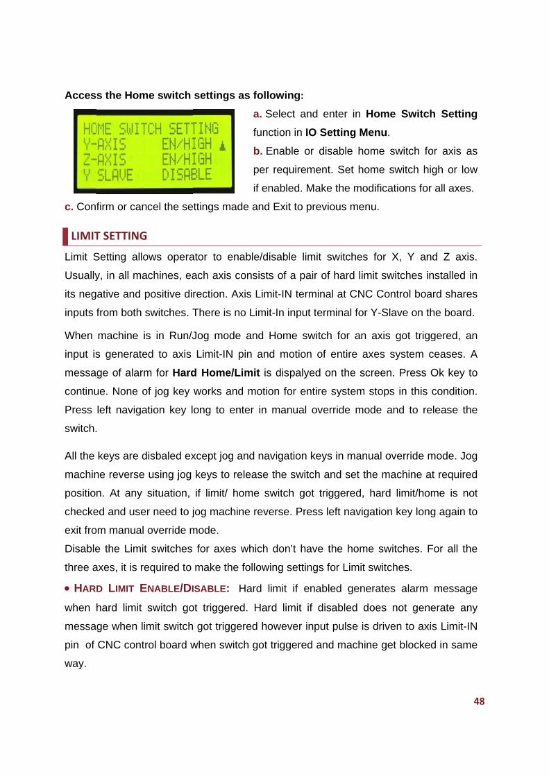
Acces
c. Conf
LIMIT
Limit S
Usually
its neg
inputs f
When
input is
messa
continu
Press
switch.
All the
machin
position
checke
exit fro
Disable
three a
HAR
when h
messa
pin of
way.
s the Hom
firm or can
T SETTING
Setting allo
y, in all ma
ative and
from both
machine i
s generate
ge of alarm
ue. None o
left naviga
.
keys are d
ne reverse
n. At any
ed and use
om manual
e the Limit
axes, it is re
D LIMIT E
hard limit
ge when li
CNC cont
me switch
ncel the se
G
ows opera
achines, ea
positive di
switches. T
is in Run/J
ed to axis
m for Hard
of jog key
ation key l
disbaled ex
using jog
situation,
er need to j
override m
t switches
equired to
ENABLE/DI
switch go
imit switch
rol board w
settings a
ttings mad
ator to ena
ach axis co
rection. Ax
There is no
Jog mode
Limit-IN p
d Home/L
works and
ong to en
xcept jog a
keys to re
if limit/ ho
jog machin
mode.
for axes w
make the
ISABLE: H
ot triggered
got trigge
when switc
as followin
a. Selec
function
b. Enab
per requ
if enable
de and Exit
able/disabl
onsists of
xis Limit-IN
o Limit-In i
and Hom
pin and mo
imit is dis
d motion fo
ter in man
and naviga
elease the
ome switch
ne reverse
which don
following s
Hard limit
d. Hard lim
ered howev
ch got trigg
ng:
ct and ent
n in IO Sett
ble or disa
uirement.
ed. Make t
t to previou
le limit sw
a pair of h
N terminal a
nput termi
me switch f
otion of en
palyed on
or entire sy
nual overri
tion keys i
switch and
h got trigg
. Press left
n’t have the
settings for
if enabled
mit if disa
ver input p
gered and
er in Hom
ting Menu
able home
Set home
the modific
us menu.
witches for
hard limit s
at CNC Co
nal for Y-S
for an axis
ntire axes
the scree
ystem stop
de mode
n manual o
d set the m
gered, hard
ft navigatio
e home sw
r Limit swit
d generate
bled does
pulse is driv
machine g
me Switch
u.
switch for
switch hig
cations for
r X, Y and
switches in
ontrol boar
Slave on th
s got trigg
system c
n. Press O
ps in this c
and to rel
override m
machine at
d limit/hom
on key long
witches. Fo
tches.
es alarm
s not gene
ven to axis
get blocked
48
h Setting
r axis as
gh or low
all axes.
d Z axis.
stalled in
rd shares
he board.
gered, an
eases. A
Ok key to
condition.
ease the
mode. Jog
t required
me is not
g again to
or all the
message
erate any
s Limit-IN
d in same
8
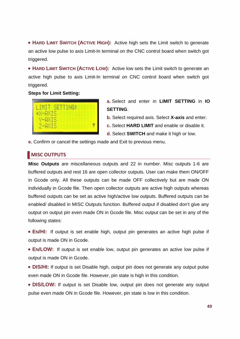
HAR
an acti
triggere
HAR
active
triggere
Steps
e. Conf
MISC
Misc O
buffere
in Gco
individu
buffere
enable
output
followin
EN/H
output
EN/L
output
DIS/
even m
DIS/
pulse e
D LIMIT SW
ve low pul
ed.
D LIMIT SW
high pulse
ed.
for Limit S
firm or can
C OUTPUT
Outputs a
ed outputs
ode only. A
ually in Gc
ed outputs
ed/ disabled
on output
ng states:
HI: If outp
is made O
LOW: If o
is made O
/HI: If outp
made ON in
/LOW: If o
even made
WITCH (AC
se to axis
WITCH (AC
e to axis
Setting:
ncel the se
S
are miscell
and rest 1
All these o
code file. T
can be se
d in MISC
pin even m
put is set
ON in Gcod
output is s
ON in Gcod
put is set D
n Gcode fil
output is s
e ON in Gc
CTIVE HIGH
Limit-In te
CTIVE LOW
Limit-In te
ttings mad
laneous o
6 are open
outputs ca
Then open
et as active
Outputs fu
made ON i
enable hig
de.
et enable
de.
Disable hig
le. Howeve
set Disable
code file. H
H): Active
rminal on t
W): Active l
erminal on
a. Select
SETTING
b. Select
c. Select
d. Select
de and Exit
utputs and
n collector
an be mad
collector o
e high/activ
unction. Bu
in Gcode f
gh, output
low, outpu
h, output p
er, pin stat
e low, out
However, p
e high sets
the CNC c
low sets th
n CNC con
and ente
G.
required a
HARD LIM
SWITCH a
t to previou
d 22 in nu
outputs. U
de OFF co
outputs are
ve low outp
uffered out
file. Misc o
pin gener
ut pin gen
pin does n
e is high in
tput pin do
in state is
s the Limit
control boa
he Limit sw
ntrol board
er in LIMI
xis. Select
MIT and en
and make
us menu.
umber. Mis
User can m
ollectively
e active hig
puts. Buffe
tput if disa
utput can
rates an a
erates an
not generat
n this cond
oes not ge
low in this
switch to
ard when s
witch to gen
d when sw
T SETTIN
t X-axis an
nable or dis
it high or lo
sc outputs
make them
but are m
gh outputs
ered output
bled don’t
be set in a
active high
active low
te any outp
ition.
enerate an
condition.
49
generate
switch got
nerate an
witch got
NG in IO
nd enter.
sable it.
ow.
s 1-6 are
ON/OFF
made ON
whereas
ts can be
give any
any of the
h pulse if
w pulse if
put pulse
ny output
9
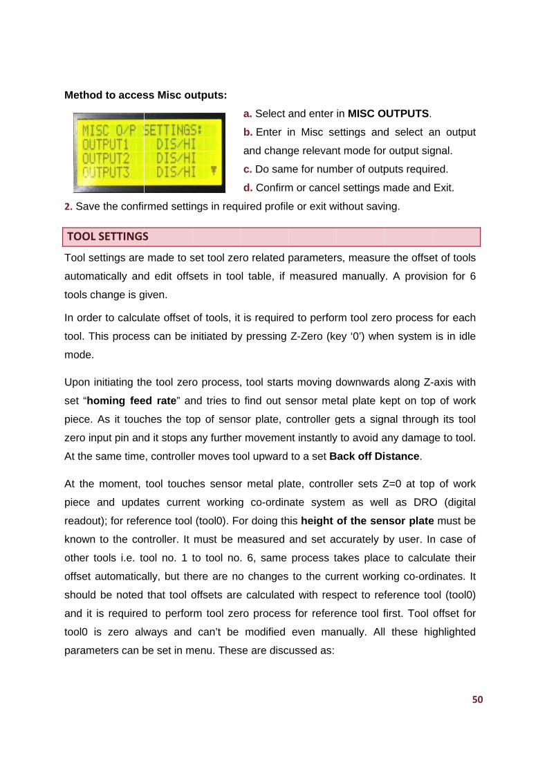
Metho
2. Save
TOOL
Tool se
automa
tools ch
In orde
tool. Th
mode.
Upon i
set “ho
piece.
zero in
At the s
At the
piece
readou
known
other t
offset a
should
and it
tool0 i
parame
d to acces
e the confi
SETTINGS
ettings are
atically and
hange is g
er to calcul
his proces
nitiating th
oming fee
As it touc
put pin an
same time
moment,
and upda
ut); for refe
to the con
tools i.e. to
automatica
be noted
is required
s zero alw
eters can b
ss Misc ou
rmed settin
S
made to s
d edit offs
given.
late offset
s can be i
he tool zero
ed rate” an
ches the to
d it stops a
e, controller
tool touch
ates curren
erence tool
ntroller. It
ool no. 1 t
ally, but th
that tool o
d to perfor
ways and
be set in m
utputs:
ngs in requ
set tool zer
sets in too
of tools, it
nitiated by
o process,
nd tries to
op of sens
any further
r moves to
hes sensor
nt working
(tool0). Fo
must be m
to tool no.
ere are no
offsets are
rm tool zer
can’t be
menu. Thes
a. Select a
b. Enter i
and chang
c. Do sam
d. Confirm
uired profile
ro related
ol table, if
is required
y pressing
, tool starts
find out s
sor plate, c
r movemen
ool upward
r metal pla
g co-ordin
or doing th
measured
. 6, same
o changes
e calculate
ro process
modified
se are disc
and enter
in Misc se
ge relevan
me for num
m or cance
e or exit w
parameter
measured
d to perfor
Z-Zero (ke
s moving d
sensor me
controller g
nt instantly
to a set B
ate, contro
nate syste
his height
and set ac
process t
to the cu
d with res
s for refere
even ma
cussed as:
in MISC O
ettings and
nt mode for
mber of outp
el settings m
without savi
rs, measure
manually
rm tool zer
ey ‘0’) whe
downward
tal plate k
gets a sign
y to avoid a
ack off Di
oller sets Z
m as wel
of the sen
ccurately b
takes place
rrent work
pect to ref
ence tool f
nually. All
OUTPUTS.
d select a
r output sig
puts requir
made and
ng.
e the offse
y. A provis
ro process
en system
s along Z-
kept on top
nal throug
any damag
stance.
Z=0 at top
ll as DRO
nsor plate
by user. In
e to calcu
king co-ord
ference to
first. Tool
these hig
50
an output gnal.
red.
Exit.
et of tools
sion for 6
for each
is in idle
-axis with
p of work
h its tool
ge to tool.
p of work
O (digital
e must be
n case of
late their
dinates. It
ol (tool0)
offset for
ghlighted
0
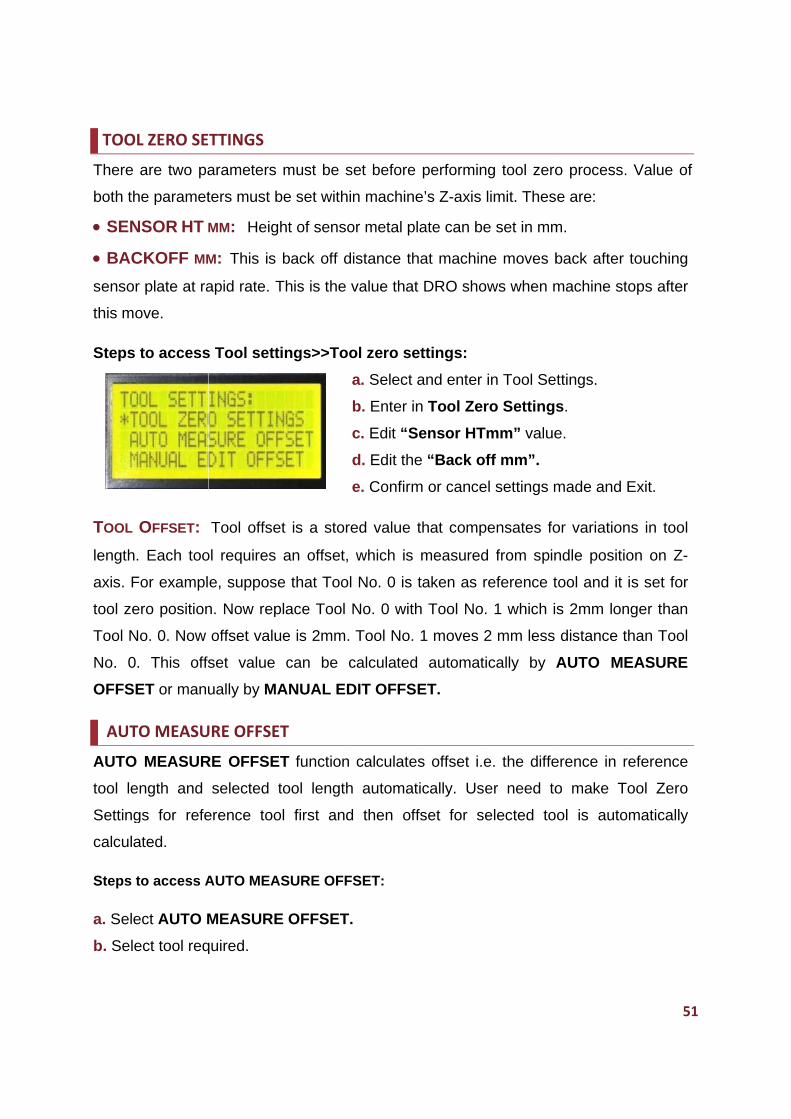
TOOL
There
both th
SEN
BAC
sensor
this mo
Steps
TOOL
length.
axis. F
tool ze
Tool N
No. 0.
OFFSE
AUTO
AUTO
tool le
Setting
calcula
Steps t
a. Sele
b. Sele
L ZERO SE
are two pa
he paramet
NSOR HT M
CKOFF MM
r plate at ra
ove.
to access
OFFSET: Each too
For exampl
ero position
o. 0. Now
. This offs
ET or manu
O MEASU
MEASUR
ngth and
gs for refe
ated.
to access A
ect AUTO M
ect tool req
TTINGS
arameters
ters must b
MM: Heig
M: This is
apid rate. T
s Tool sett
Tool offse
ol requires
e, suppose
n. Now rep
offset valu
set value
ually by MA
URE OFFSE
RE OFFSE
selected
erence too
AUTO MEA
MEASURE
quired.
must be s
be set with
ht of senso
back off d
This is the
tings>>To
et is a stor
an offset,
e that Too
place Tool
ue is 2mm.
can be
ANUAL ED
ET
ET function
tool length
ol first and
ASURE OFF
E OFFSET
set before
in machine
or metal pl
distance th
value that
ool zero se
a. Select a
b. Enter in
c. Edit “S
d. Edit the
e. Confirm
red value t
, which is
ol No. 0 is
No. 0 with
. Tool No.
calculated
DIT OFFS
n calculate
h automat
d then off
FSET:
T.
performin
e’s Z-axis
late can be
hat machin
t DRO sho
ettings:
and enter
n Tool Zer
Sensor HTm
e “Back of
m or cance
that comp
measured
taken as r
h Tool No.
1 moves 2
automati
ET.
s offset i.e
tically. Use
fset for se
g tool zero
limit. Thes
e set in mm
ne moves b
ws when m
in Tool Se
ro Settings
mm” value
ff mm”.
l settings m
ensates fo
d from spin
reference t
1 which i
2 mm less
ically by A
e. the diffe
er need to
elected to
o process.
e are:
m.
back after
machine st
ttings.
s.
e.
made and
or variation
ndle positi
tool and it
s 2mm lon
distance t
AUTO ME
erence in r
o make T
ol is auto
51
. Value of
touching
tops after
Exit.
ns in tool
on on Z-
is set for
nger than
than Tool
EASURE
reference
Tool Zero
omatically
1
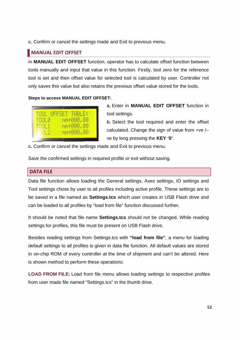
c. Conf
MAN
In MAN
tools m
tool is
only sa
Steps t
c. Conf
Save th
DATA
Data fi
Tool se
be sav
can be
It shou
setting
Beside
default
in on-c
is show
LOAD
from us
firm or can
NUAL EDIT
NUAL EDI
manually an
set and th
aves this va
to access M
firm or can
he confirm
A FILE
le function
ettings cho
ved in a file
e loaded to
uld be note
s for profile
es reading
t settings to
chip ROM
wn method
FROM FIL
ser made f
ncel the se
T OFFSET
T OFFSET
nd input th
hen offset
alue but al
MANUAL E
ncel the se
ed settings
n allows lo
ose by use
e named a
all profiles
ed that file
es, this file
settings fr
o all profile
of every c
to perform
LE: Load f
file named
ttings mad
T function,
hat value i
value for s
so retains
EDIT OFFSE
ttings mad
s in require
oading the
r to all pro
as Settings
s by “load f
name Set
e must be p
rom Settin
es is given
ontroller a
m these op
from file m
“Settings.
de and Exit
operator h
n this func
selected to
the previo
ET:
a. Enter in
tool settin
b. Select
calculated
ve by long
de and Exit
ed profile o
General s
files includ
s.tcs whic
from file” fu
ttings.tcs
present on
gs.tcs with
n in data fil
t the time
perations:
menu allow
tcs” in the
t to previou
has to calc
ction. Firstl
ool is calcu
ous offset v
n MANUA
gs.
the tool r
d. Change
g pressing
t to previou
or exit with
settings, Ax
ding active
ch user cre
unction dis
should no
USB Flas
h “load fro
e function.
of shipme
ws loading
thumb driv
us menu.
culate offse
ly, tool zer
ulated by u
value store
AL EDIT O
equired an
the sign o
the KEY ‘
us menu.
out saving
xes setting
profile. Th
eates in US
scussed fu
ot be chan
sh drive.
om file”, a
. All defaul
nt and can
settings to
ve.
et function
ro for the r
user. Cont
ed for the to
OFFSET fu
nd enter t
of value fro
0’.
g.
gs, IO sett
hese settin
SB Flash d
rther.
ged. While
a menu fo
lt values a
n’t be alter
o respectiv
52
between
reference
troller not
ools.
unction in
he offset
om +ve /–
tings and
ngs are to
drive and
e reading
or loading
re stored
red. Here
ve profiles
2
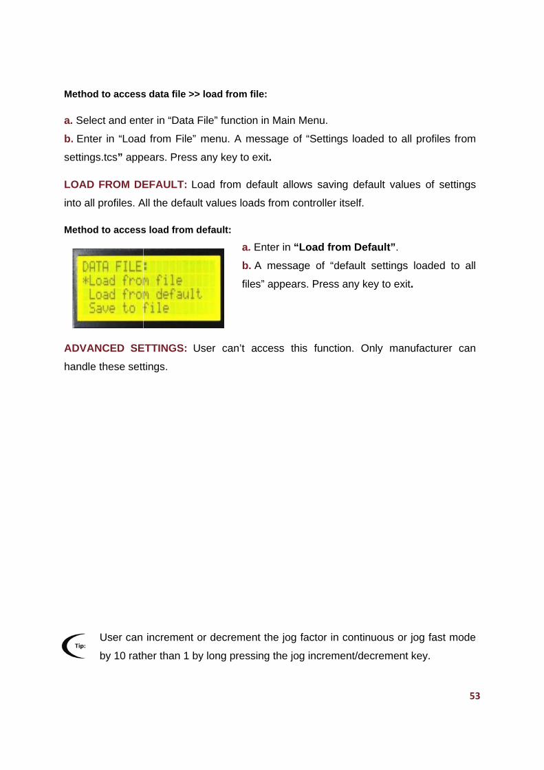
Method
a. Sele
b. Ente
setting
LOAD
into all
Method
ADVAN
handle
d to access
ect and ent
er in “Load
s.tcs” app
FROM DE
profiles. A
d to access
NCED SE
e these sett
User can
by 10 rath
s data file >
ter in “Data
d from File
ears. Pres
EFAULT:
All the defa
s load from
ETTINGS:
tings.
increment
her than 1
>> load fro
a File” func
e” menu. A
ss any key
Load from
ult values
m default:
User can
t or decrem
by long pr
m file:
ction in Ma
A message
to exit.
m default a
loads from
a. Enter in
b. A mes
files” appe
’t access
ment the jo
ressing the
in Menu.
e of “Settin
allows savi
m controller
n “Load fr
sage of “d
ears. Press
this funct
og factor in
e jog increm
ngs loaded
ing default
r itself.
rom Defau
default set
s any key t
tion. Only
n continuo
ment/decre
d to all pro
t values o
ult”.
ttings load
to exit.
y manufac
us or jog f
ement key.
53
ofiles from
of settings
ded to all
turer can
fast mode
3
54
DEFAULT PROFILES VALUES
1. GENERAL SETTINGS
Step pulse width: 4us
Path mode: Continuous mode
Max Deviation: 5
Help: Keypad function and About
2. AXIS SETTINGS (FOR ALL AXES):
Drive: All axes enabled.
Step pin: Active High
Dir pin: Active High
Steps/mm: 250 steps (X, Y and Z)
Velocity (mm/min): 10000 mm/min
Acceleration: 100 mm/sec².
Z inhibit: Disable
3. IO SETTINGS:
SPINDLE SETTINGS:
Spindle: Enable
Step pin: Active High
MAX RPM: 20000
MIN RPM: 6000
Dwell time: 4 seconds
Step frequency: 1 KHz
HOME SETTINGS (FOR ALL AXES):
Seek rate: 750.00mm/min
Feed rate: 100.00mm/min
Pull off: 1 mm
Safe Z Height: 10mm
Debounce delay: 100mS
HOME SWITCH SETTINGS (FOR ALL AXES):
Home switch Enable: Active High
Y‐Slave: Disable
LIMIT SETTINGS (FOR ALL AXES):
Hard Limit Switch: Active High
MISC OUTPUTS: All disable high
4. TOOL ZERO SETTINGS:
TOOL ZERO SETTINGS:
Sensor Height: 2mm
Back off: 20mm
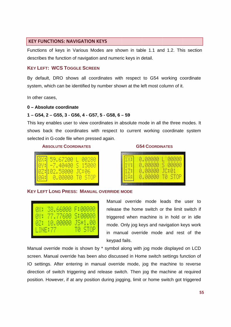
KEY FU
Functio
describ
KEY LE
By def
system
In othe
0 – Ab
1 – G5
This ke
shows
selecte
KEY LE
Manua
screen
IO set
directio
position
UNCTION
ons of key
bes the fun
EFT: WCS
fault, DRO
m, which ca
er cases,
bsolute coo
54, 2 – G55
ey enables
back the
ed in G-cod
ABSOLUTE
EFT LONG
al override
. Manual o
tings. Afte
on of switc
n. Howeve
S: NAVIGA
ys in Vario
nction of na
S TOGGLE
O shows
an be ident
ordinate
5, 3 - G56,
s user to v
e coordina
de file whe
E COORDINA
PRESS: M
mode is s
override ha
er entering
ch triggerin
er, if at any
ATION KE
ous Mode
avigation a
SCREEN
all coordin
tified by nu
4 - G57, 5
view coordi
ates with
en pressed
ATES
MANUAL O
shown by *
as been al
g in manu
ng and re
y position
YS
es are sho
and numeri
nates with
umber show
5 - G58, 6 –
inates in a
respect to
again.
OVERRIDE M
Manual
release
triggere
mode. O
in man
keypad
* symbol a
so discuss
ual overrid
lease swit
during jogg
own in tab
ic keys in d
h respect
wn at the le
– 59
absolute m
o current
G54
MODE
override
the home
d when m
Only jog ke
ual overri
fails.
along with
sed in Hom
de mode,
tch. Then
ging, limit
ble 1.1 and
detail.
to G54 w
eft most co
ode in all t
working
4 COORDIN
mode le
e switch o
machine is
eys and na
ide mode
jog mode
me switch
jog the m
jog the m
or home s
d 1.2. Thi
working co
olumn of it
the three m
coordinate
NATES
eads the
r the limit
in hold o
avigation k
and res
displayed
settings fu
machine to
machine at
switch got
55
is section
oordinate
.
modes. It
e system
user to
switch if
or in idle
keys work
st of the
d on LCD
unction of
o reverse
required
triggered
5
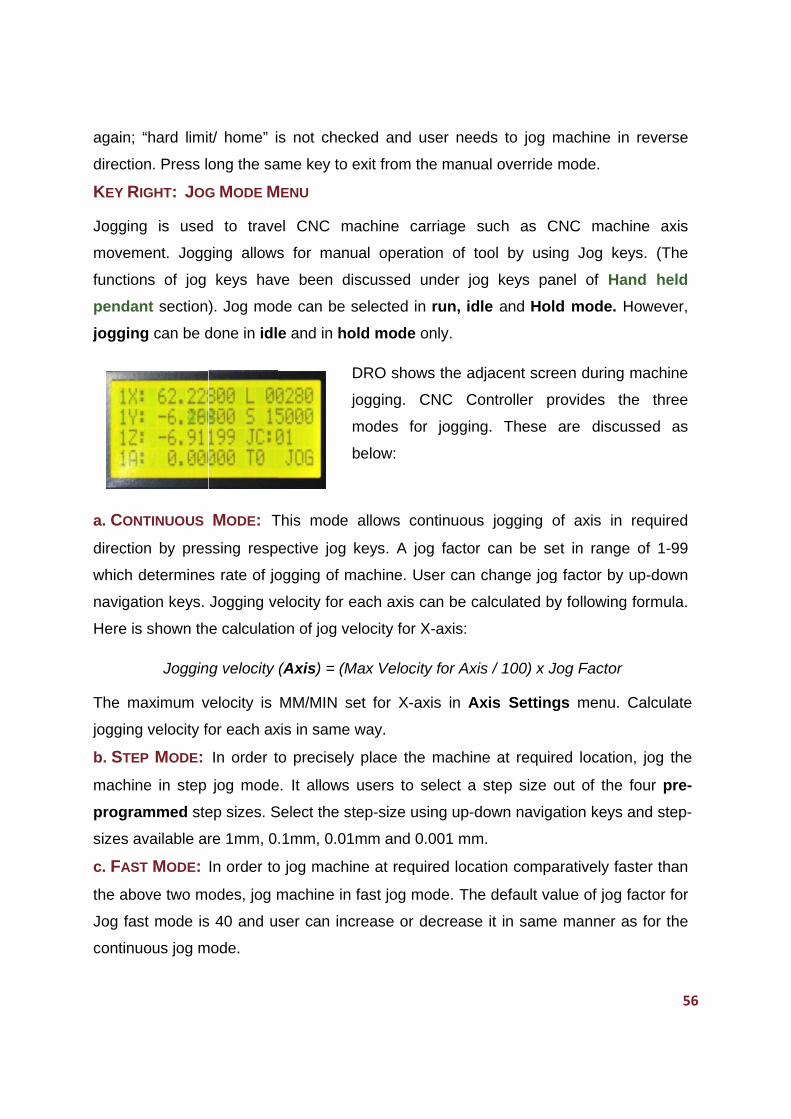
again;
directio
KEY R
Joggin
movem
functio
penda
joggin
a. CON
directio
which d
navigat
Here is
The m
jogging
b. STE
machin
progra
sizes a
c. FAS
the abo
Jog fas
continu
“hard limi
on. Press lo
RIGHT: JOG
g is used
ment. Jogg
ns of jog
nt section
g can be d
NTINUOUS
on by pres
determines
tion keys.
s shown th
Joggin
aximum v
g velocity fo
EP MODE:
ne in step
ammed ste
available ar
T MODE:
ove two mo
st mode is
uous jog m
t/ home” i
ong the sa
G MODE M
d to trave
ging allows
keys hav
). Jog mod
done in idl
MODE: T
ssing resp
s rate of jo
Jogging ve
e calculatio
g velocity
velocity is
or each ax
In order t
jog mode
ep sizes. S
re 1mm, 0
In order to
odes, jog m
s 40 and u
mode.
s not chec
ame key to
MENU
el CNC m
s for man
ve been d
de can be
e and in ho
This mode
ective jog
ogging of m
elocity for
on of jog v
(Axis) = (M
MM/MIN s
xis in same
o precisely
e. It allows
Select the s
.1mm, 0.0
o jog mach
machine in
ser can in
cked and
exit from t
machine c
nual opera
discussed
selected i
old mode
DRO show
jogging.
modes fo
below:
e allows c
keys. A j
machine. U
each axis
velocity for
Max Veloci
set for X-a
e way.
y place th
s users to
step-size u
1mm and 0
hine at requ
n fast jog m
crease or
user need
the manua
carriage su
ation of to
under jog
n run, idle
only.
ws the adj
CNC Co
or jogging
ontinuous
og factor
User can c
can be ca
X-axis:
ity for Axis
axis in Ax
e machine
select a s
using up-do
0.001 mm.
uired locat
mode. The
decrease
ds to jog m
al override
uch as C
ol by usin
g keys pa
e and Hold
acent scre
ntroller pr
g. These
jogging o
can be se
change jog
lculated by
s / 100) x J
xis Setting
e at require
step size o
own naviga
.
tion compa
default va
it in same
machine in
mode.
CNC mach
ng Jog ke
nel of Ha
d mode. H
een during
rovides th
are discu
of axis in
et in range
g factor by
y following
Jog Factor
gs menu.
ed location
out of the
ation keys
aratively fa
alue of jog
e manner a
56
n reverse
hine axis
eys. (The
and held
However,
machine
he three
ussed as
required
e of 1-99
up-down
g formula.
Calculate
n, jog the
four pre-
and step-
aster than
factor for
as for the
6
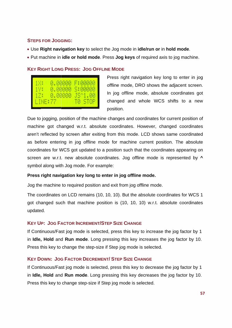
STEPS
Use R
Put m
KEY R
Due to
machin
aren’t r
as bef
coordin
screen
symbo
Press
Jog the
The co
got ch
update
KEY U
If Cont
in Idle,
Press t
KEY D
If Cont
in Idle,
Press t
S FOR JOGG
Right navi
machine in
RIGHT LONG
jogging, p
ne got ch
reflected b
fore enteri
nates for W
are w.r.t
l along wit
right navi
e machine
oordinates
anged suc
ed.
P: JOG FA
tinuous/Fas
, Hold and
this key to
OWN: JOG
tinuous/Fas
, Hold and
this key to
GING:
igation ke
idle or ho
G PRESS:
position of
anged w.
by screen a
ng in jog
WCS got u
. new abs
h Jog mod
gation key
to required
on LCD re
ch that ma
ACTOR INC
st jog mod
d Run mo
change th
G FACTOR
st jog mod
d Run mo
change st
ey to select
old mode.
JOG OFFL
the machin
r.t. absolu
after exitin
offline m
pdated to
solute coo
de. For exa
y long to e
d position
emains (10
achine po
CREMENT/S
de is select
ode. Long
he step-size
R DECREME
de is select
ode. Long
tep-size if S
t the Jog m
Press Jog
LINE MODE
Press ri
offline m
In jog o
changed
position
ne change
ute coordin
ng from thi
ode for m
a position
ordinates.
ample:
enter in jo
and exit fro
0, 10, 10).
sition is (1
STEP SIZE
ted, press
pressing t
e if Step jo
ENT/ STEP
ted, press
pressing th
Step jog m
mode in idl
g keys of r
E
ight naviga
mode, DRO
offline mod
d and wh
.
es and coo
nates. Ho
s mode. L
machine cu
such that
Jog offline
og offline m
om jog offl
But the ab
10, 10, 10
E CHANGE
this key to
this key inc
og mode is
SIZE CHA
this key to
his key de
mode is sele
e/run or in
required ax
ation key
O shows th
de, absolu
hole WCS
rdinates fo
owever, ch
LCD shows
urrent pos
the coordi
e mode is
mode.
ine mode.
bsolute coo
0) w.r.t. ab
o increase
creases th
selected.
ANGE
o decrease
ecreases th
ected.
n hold mo
xis to jog m
long to en
he adjacen
ute coordin
S shifts to
or current p
hanged co
s same co
sition. The
inates app
s represen
ordinates fo
bsolute co
the jog fa
he jog facto
e the jog fa
he jog fact
57
ode. machine.
nter in jog
nt screen.
nates got
o a new
position of
oordinates
oordinated
absolute
pearing on
nted by ^
or WCS 1
oordinates
actor by 1
or by 10.
actor by 1
or by 10.
7
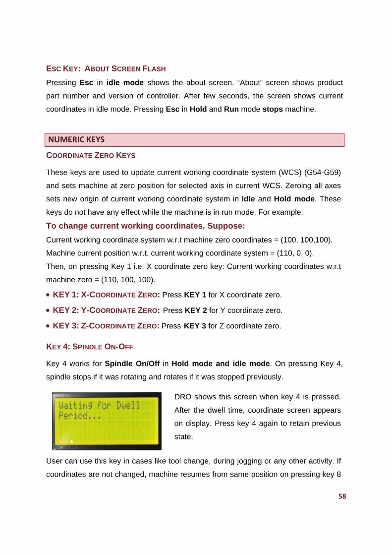
ESC K
Pressin
part nu
coordin
NUME
COORD
These
and se
sets ne
keys do
To cha
Curren
Machin
Then, o
machin
KEY
KEY
KEY
KEY 4:
Key 4
spindle
User c
coordin
EY: ABOU
ng Esc in
umber and
nates in idl
ERIC KEYS
DINATE ZE
keys are u
ets machin
ew origin o
o not have
ange cur
nt working c
ne current
on pressin
ne zero = (
Y 1: X-COO
Y 2: Y-COO
Y 3: Z-COO
: SPINDLE
works for
e stops if it
an use this
nates are n
UT SCREEN
idle mod
d version o
e mode. P
S
ERO KEYS
used to up
e at zero
of current w
e any effect
rent work
coordinate
position w
ng Key 1 i.
110, 100,
ORDINATE Z
ORDINATE Z
ORDINATE Z
ON-OFF
Spindle O
was rotati
s key in ca
not change
N FLASH
de shows
of controlle
Pressing Es
pdate curre
position fo
working co
t while the
king coor
e system w
.r.t. curren
e. X coord
100).
ZERO: Pre
ZERO: Pre
ZERO: Pre
On/Off in H
ng and rot
ases like to
ed, machin
the about
er. After fe
sc in Hold
ent working
or selected
oordinate s
machine i
rdinates,
w.r.t machin
t working c
dinate zero
ess KEY 1
ess KEY 2
ess KEY 3
Hold mod
tates if it w
DRO show
After the
on display
state.
ool change
ne resumes
screen. “A
ew second
and Run
g coordina
d axis in cu
system in
is in run m
Suppose
ne zero coo
coordinate
o key: Curr
for X coor
for Y coor
for Z coor
de and idl
was stopped
ws this sc
dwell time
y. Press k
e, during jo
s from sam
About” scr
ds, the scr
mode stop
ate system
urrent WCS
Idle and H
ode. For e
e:
ordinates =
e system =
rent workin
rdinate zer
rdinate zer
rdinate zero
e mode. O
d previous
creen when
e, coordina
ey 4 again
ogging or a
me position
reen show
reen show
ps machin
(WCS) (G
S. Zeroing
Hold mod
example:
= (100, 100
(110, 0, 0)
ng coordina
o.
ro.
o.
On pressin
ly.
n key 4 is
ate screen
n to retain
any other a
n on press
58
s product
ws current
e.
G54-G59)
g all axes
e. These
0,100).
).
ates w.r.t
ng Key 4,
pressed.
appears
previous
activity. If
ing key 8
8
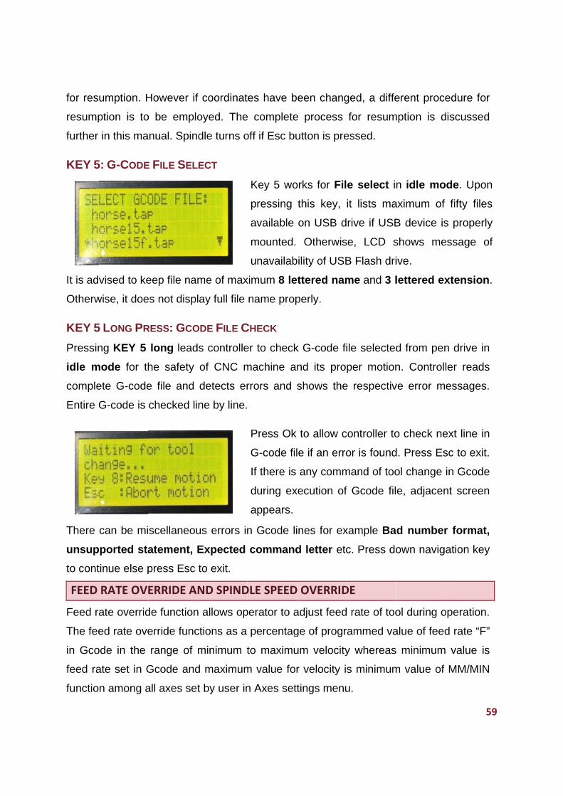
for res
resump
further
KEY 5
It is ad
Otherw
KEY 5
Pressin
idle m
comple
Entire G
There
unsup
to cont
FEED
Feed ra
The fee
in Gco
feed ra
functio
umption. H
ption is to
in this ma
5: G-CODE
vised to ke
wise, it doe
5 LONG PR
ng KEY 5
mode for th
ete G-code
G-code is
can be mi
ported sta
tinue else p
RATE OVE
ate overrid
ed rate ove
ode in the
ate set in G
n among a
However if
o be emplo
nual. Spin
E FILE SEL
eep file nam
es not displ
RESS: GCO
long lead
he safety
e file and
checked li
scellaneou
atement, E
press Esc
ERRIDE AN
de function
erride func
range of m
Gcode and
all axes set
f coordinat
oyed. The
dle turns o
ECT
me of max
lay full file
ODE FILE C
s controlle
of CNC m
detects er
ne by line.
us errors in
Expected
to exit.
ND SPIND
n allows op
ctions as a
minimum t
d maximum
t by user in
es have b
e complete
off if Esc bu
Key 5 wo
pressing
available
mounted.
unavailab
ximum 8 le
name prop
CHECK
er to check
machine a
rrors and s
Press Ok
G-code fil
If there is
during ex
appears.
n Gcode li
command
DLE SPEED
perator to a
percentag
to maximu
m value for
n Axes sett
een chang
e process
utton is pre
orks for Fil
this key,
on USB d
Otherwis
bility of USB
ttered nam
perly.
k G-code fi
nd its pro
shows the
to allow c
le if an erro
any comm
xecution of
ines for ex
d letter etc
D OVERRID
adjust feed
ge of progr
um velocity
r velocity i
tings menu
ged, a diffe
for resum
essed.
e select i
it lists ma
rive if USB
se, LCD s
B Flash dri
me and 3 l
ile selected
per motion
e respectiv
controller to
or is found
mand of too
f Gcode fil
xample Ba
c. Press do
DE
d rate of too
rammed va
y whereas
s minimum
u.
erent proce
mption is d
n idle mo
aximum of
B device is
shows me
ive.
lettered ex
d from pen
n. Controll
ve error m
o check ne
d. Press Es
ol change
e, adjacen
d number
own navig
ol during o
alue of feed
s minimum
m value of
59
edure for
discussed
ode. Upon
fifty files
s properly
essage of
xtension.
n drive in
ler reads
essages.
ext line in
sc to exit.
in Gcode
nt screen
r format,
ation key
operation.
d rate “F”
value is
MM/MIN
9
60
Spindle speed override function allows operator to adjust speed of spindle during
operation. The override functions as a percentage of programmed value of spindle
speed “S” in Gcode file in range of MIN RPM to MAX RPM function set by user in
spindle setting menu.
KEY 6: OVERRIDE SCREEN
When machine is in either of 3 modes, pressing key 6 shows override screen on LCD.
User can change percentage of feed rate override using Z jog keys and percentage of
spindle speed override using 4th jog keys. Press ‘Z+’ key to increase feed rate override
and ‘Z-’ key to decrease the feed rate override. Press ‘Y+’ to reset feed rate. Press
‘4+’ Key to increase spindle speed override and ‘4-’ key to decrease spindle speed
override. Press ‘Y+’ to reset Spindle speed. Press Ok key to exit from override screen.
However, minimum value for feed override is 10% of programmed feed rate and
maximum value is 200% of programmed feed rate. However, maximum achievable
feed rate for tool can’t reach beyond MM/MIN.
Similarly, maximum value for spindle speed override is 10% of spindle speed and
maximum value of spindle speed override is 200% of programmed spindle speed in G
code file. However, maximum reachable spindle can’t cross the MAX RPM set in
spindle setting function of IO settings.
KEY 7: GO TO ZERO
Press key 7 to make entire axes system to go to Zero position set for that working
coordinate system in idle mode.
When key 7 is pressed, Go to Zero action takes place in following steps:
Step 1: When key 7 is pressed, Z-axis moves to Z-safe height. However, if Z-axis is
already at or at height more than Z-safe height, this step gets omitted and next step is
accomplished directly.
Step 2: Coordinated motion of X-axis and Y-axis to their respective zero-position w.r.t.
WCS takes place.
Step 3: After step 2, the motion of Z-axis to its respective zero position takes place.
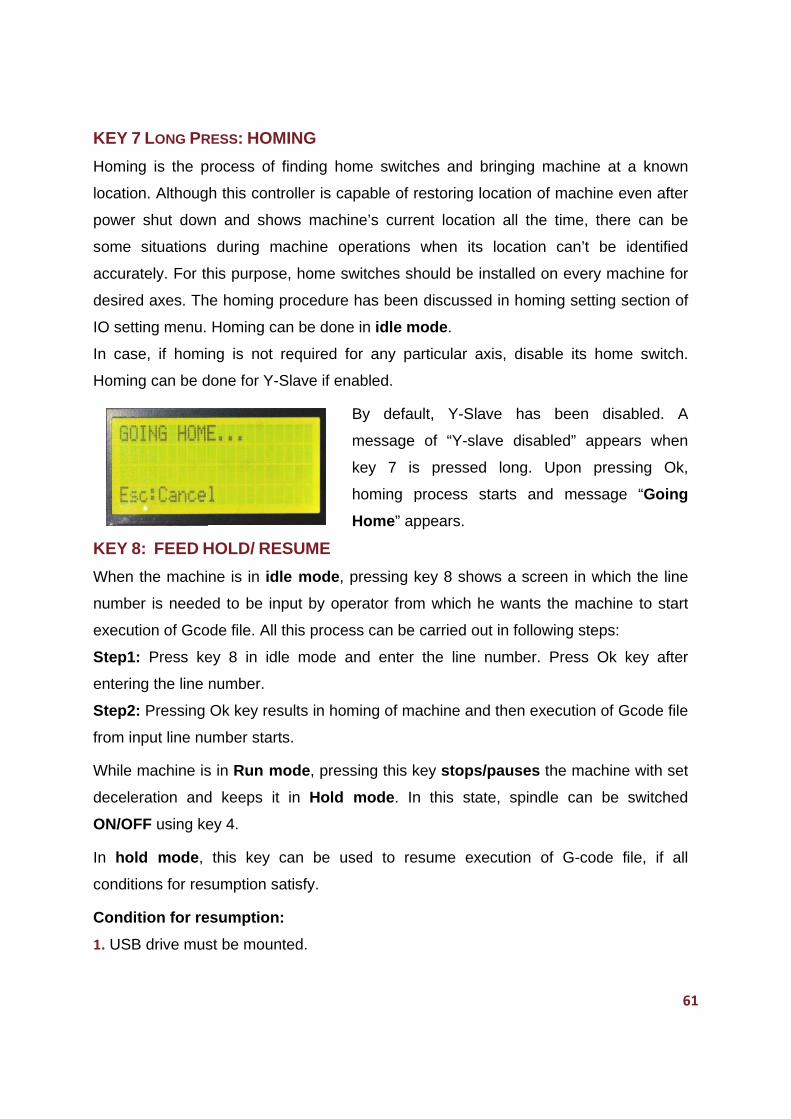
KEY 7
Homing
location
power
some
accura
desired
IO sett
In case
Homing
KEY 8
When
numbe
execut
Step1:
enterin
Step2:
from in
While m
decele
ON/OF
In hol
conditio
Condit
1. USB
7 LONG PR
g is the p
n. Althoug
shut dow
situations
ately. For th
d axes. Th
ing menu.
e, if homin
g can be d
8: FEED H
the machi
er is neede
ion of Gco
Press ke
ng the line
Pressing
nput line nu
machine is
ration and
FF using ke
d mode,
ons for res
tion for re
B drive mus
RESS: HOM
rocess of
h this cont
n and sho
during m
his purpos
e homing
Homing ca
ng is not
done for Y-
HOLD/ RE
ne is in id
ed to be in
ode file. All
ey 8 in id
number.
Ok key res
umber start
s in Run m
d keeps it
ey 4.
this key
sumption s
esumption
st be moun
MING
finding ho
troller is ca
ows mach
machine o
e, home s
procedure
an be done
required f
-Slave if en
ESUME
dle mode,
nput by op
this proce
le mode a
sults in hom
ts.
mode, pres
t in Hold
can be u
atisfy.
n:
nted.
ome switch
apable of r
ine’s curre
perations
switches sh
e has been
e in idle m
for any pa
nabled.
By defau
message
key 7 is
homing p
Home” ap
pressing k
erator from
ess can be
and enter
ming of ma
ssing this k
mode. In
sed to re
hes and b
restoring lo
ent locatio
when its
hould be in
discussed
mode.
articular ax
ult, Y-Slav
of “Y-sla
s pressed
process s
ppears.
key 8 show
m which he
carried ou
the line n
achine and
key stops/
n this stat
esume exe
bringing ma
ocation of m
n all the t
location
nstalled on
d in homin
xis, disable
ve has b
ve disable
long. U
tarts and
ws a scree
e wants th
ut in followi
number. P
d then exec
pauses th
te, spindle
ecution of
achine at
machine e
time, there
can’t be
n every ma
g setting s
e its home
been disa
ed” appea
pon press
message
en in which
he machine
ng steps:
Press Ok k
cution of G
he machine
e can be
G-code f
61
a known
even after
e can be
identified
achine for
section of
e switch.
abled. A
ars when
sing Ok,
e “Going
h the line
e to start
key after
Gcode file
e with set
switched
file, if all
1
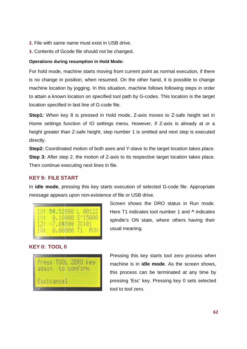
2. File w
3. Cont
Operat
For ho
is no c
machin
to attai
location
Step1:
Home
height
directly
Step2:
Step 3
Then c
KEY 9
In idle
messa
KEY 0
with same
tents of Gc
ions during
ld mode, m
change in
ne location
n a known
n specified
When ke
settings fu
greater tha
y.
Coordinat
3: After ste
continue ex
9: FILE ST
mode, pr
ge appear
0: TOOL 0
name mus
code file sh
g resumpti
machine st
position, w
n by joggin
n location o
d in last line
ey 8 is pre
unction of
an Z-safe
ted motion
ep 2, the m
xecuting ne
TART
ressing thi
rs upon non
0
st exist in
hould not b
ion in Hold
tarts movin
when resum
g. In this s
on specifie
e of G-cod
essed in H
f IO setting
height, ste
n of both ax
motion of Z
ext lines in
s key star
n-existenc
USB drive
be changed
d Mode:
ng from cu
med. On th
situation, m
ed tool path
de file.
Hold mode
gs menu.
ep number
xes and Y-
Z-axis to its
file.
rts executio
e of file or
Screen s
Here T1 i
spindle’s
usual mea
Pressing
machine
this proce
pressing
tool to too
.
d.
rrent point
he other h
machine fo
h by G-cod
, Z-axis m
However,
r 1 is omitt
-slave to th
s respectiv
on of selec
USB drive
hows the
ndicates to
ON state
aning.
this key s
is in idle
ess can b
‘Esc’ key.
ol zero.
as norma
hand, it is
ollows follow
des. This lo
moves to Z
if Z-axis
ed and ne
he target lo
ve target lo
cted G-cod
e.
DRO sta
ool numbe
, where o
starts tool
mode. As
be terminat
Pressing
l execution
possible to
wing steps
ocation is t
Z-safe heig
is already
ext step is e
ocation tak
ocation take
de file. Ap
atus in Ru
er 1 and ^
others hav
zero proce
the scree
ted at any
key 0 sets
62
n, if there
o change
s in order
the target
ght set in
y at or a
executed
es place.
es place.
ppropriate
un mode.
indicates
ving their
ess when
en shows,
y time by
s selected
2
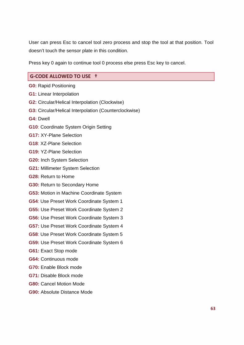
63
User can press Esc to cancel tool zero process and stop the tool at that position. Tool
doesn’t touch the sensor plate in this condition.
Press key 0 again to continue tool 0 process else press Esc key to cancel.
G‐CODE ALLOWED TO USE †
G0: Rapid Positioning
G1: Linear Interpolation
G2: Circular/Helical Interpolation (Clockwise)
G3: Circular/Helical Interpolation (Counterclockwise)
G4: Dwell
G10: Coordinate System Origin Setting
G17: XY-Plane Selection
G18: XZ-Plane Selection
G19: YZ-Plane Selection
G20: Inch System Selection
G21: Millimeter System Selection
G28: Return to Home
G30: Return to Secondary Home
G53: Motion in Machine Coordinate System
G54: Use Preset Work Coordinate System 1
G55: Use Preset Work Coordinate System 2
G56: Use Preset Work Coordinate System 3
G57: Use Preset Work Coordinate System 4
G58: Use Preset Work Coordinate System 5
G59: Use Preset Work Coordinate System 6
G61: Exact Stop mode
G64: Continuous mode
G70: Enable Block mode
G71: Disable Block mode
G80: Cancel Motion Mode
G90: Absolute Distance Mode
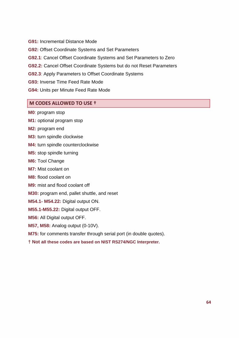
64
G91: Incremental Distance Mode
G92: Offset Coordinate Systems and Set Parameters
G92.1: Cancel Offset Coordinate Systems and Set Parameters to Zero
G92.2: Cancel Offset Coordinate Systems but do not Reset Parameters
G92.3: Apply Parameters to Offset Coordinate Systems
G93: Inverse Time Feed Rate Mode
G94: Units per Minute Feed Rate Mode
M CODES ALLOWED TO USE †
M0: program stop
M1: optional program stop
M2: program end
M3: turn spindle clockwise
M4: turn spindle counterclockwise
M5: stop spindle turning
M6: Tool Change
M7: Mist coolant on
M8: flood coolant on
M9: mist and flood coolant off
M30: program end, pallet shuttle, and reset
M54.1- M54.22: Digital output ON.
M55.1-M55.22: Digital output OFF.
M56: All Digital output OFF.
M57, M58: Analog output (0-10V).
M75: for comments transfer through serial port (in double quotes).
† Not all these codes are based on NIST RS274/NGC Interpreter.
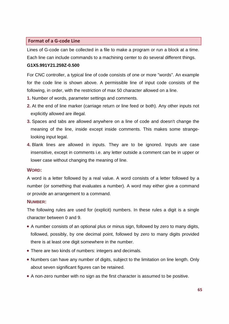
65
Format of a G‐code Line
Lines of G-code can be collected in a file to make a program or run a block at a time.
Each line can include commands to a machining center to do several different things.
G1X5.991Y21.259Z-0.500
For CNC controller, a typical line of code consists of one or more "words". An example
for the code line is shown above. A permissible line of input code consists of the
following, in order, with the restriction of max 50 character allowed on a line.
1. Number of words, parameter settings and comments.
2. At the end of line marker (carriage return or line feed or both). Any other inputs not
explicitly allowed are illegal.
3. Spaces and tabs are allowed anywhere on a line of code and doesn't change the
meaning of the line, inside except inside comments. This makes some strange-
looking input legal.
4. Blank lines are allowed in inputs. They are to be ignored. Inputs are case
insensitive, except in comments i.e. any letter outside a comment can be in upper or
lower case without changing the meaning of line.
WORD:
A word is a letter followed by a real value. A word consists of a letter followed by a
number (or something that evaluates a number). A word may either give a command
or provide an arrangement to a command.
NUMBER:
The following rules are used for (explicit) numbers. In these rules a digit is a single
character between 0 and 9.
A number consists of an optional plus or minus sign, followed by zero to many digits,
followed, possibly, by one decimal point, followed by zero to many digits provided
there is at least one digit somewhere in the number.
There are two kinds of numbers: integers and decimals.
Numbers can have any number of digits, subject to the limitation on line length. Only
about seven significant figures can be retained.
A non-zero number with no sign as the first character is assumed to be positive.
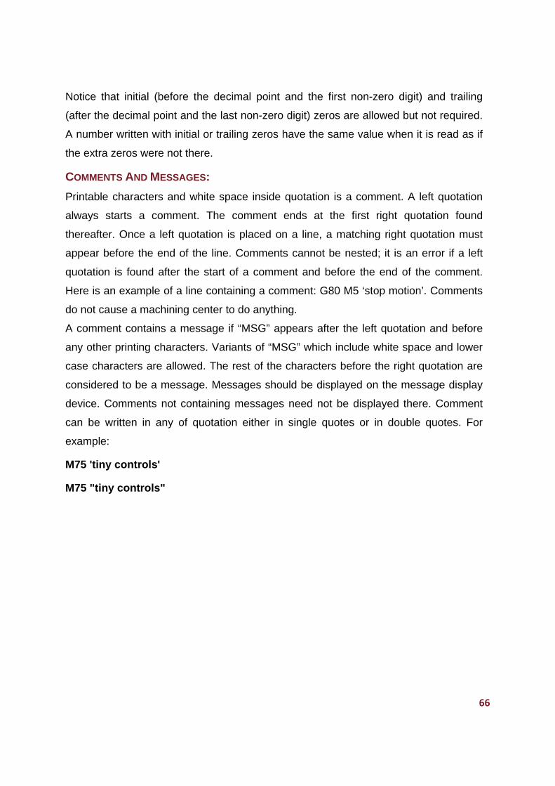
66
Notice that initial (before the decimal point and the first non-zero digit) and trailing
(after the decimal point and the last non-zero digit) zeros are allowed but not required.
A number written with initial or trailing zeros have the same value when it is read as if
the extra zeros were not there.
COMMENTS AND MESSAGES:
Printable characters and white space inside quotation is a comment. A left quotation
always starts a comment. The comment ends at the first right quotation found
thereafter. Once a left quotation is placed on a line, a matching right quotation must
appear before the end of the line. Comments cannot be nested; it is an error if a left
quotation is found after the start of a comment and before the end of the comment.
Here is an example of a line containing a comment: G80 M5 ‘stop motion’. Comments
do not cause a machining center to do anything.
A comment contains a message if “MSG” appears after the left quotation and before
any other printing characters. Variants of “MSG” which include white space and lower
case characters are allowed. The rest of the characters before the right quotation are
considered to be a message. Messages should be displayed on the message display
device. Comments not containing messages need not be displayed there. Comment
can be written in any of quotation either in single quotes or in double quotes. For
example:
M75 'tiny controls'
M75 "tiny controls"
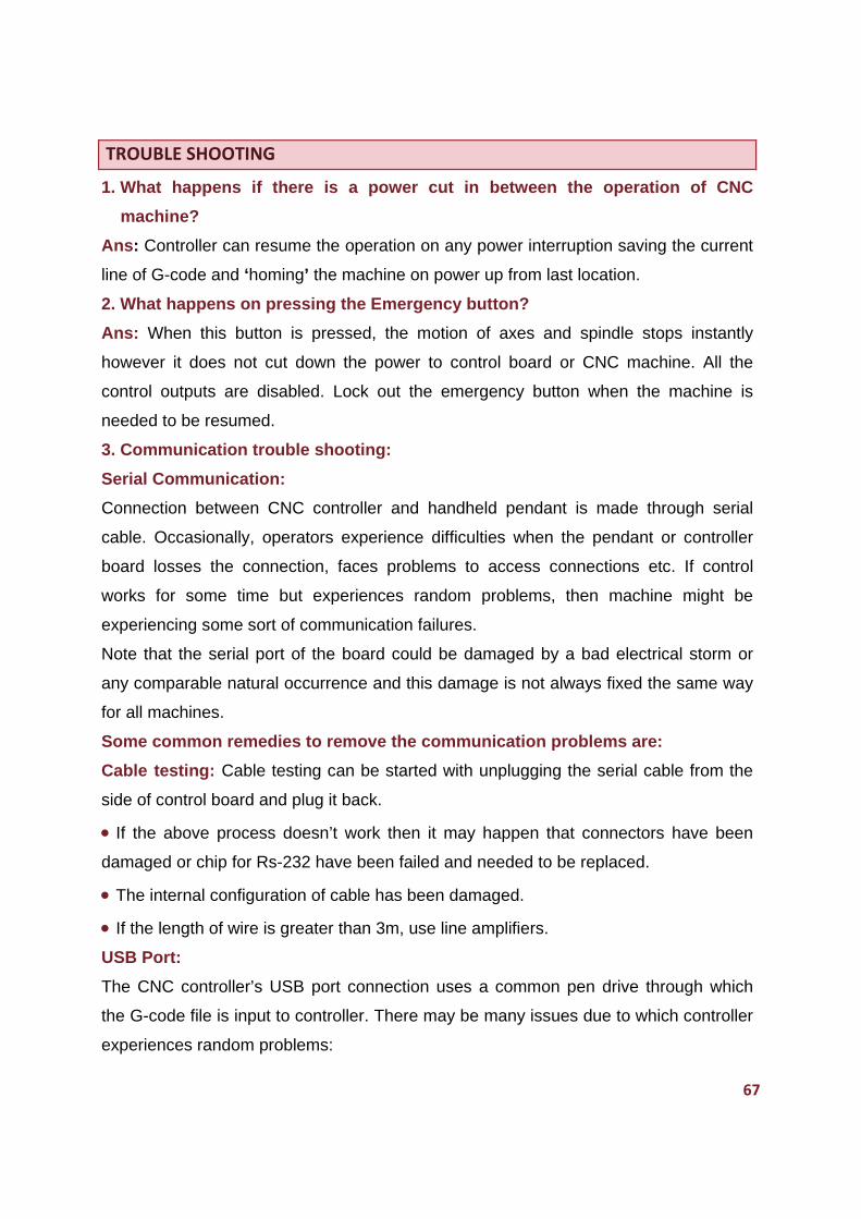
67
TROUBLE SHOOTING
1. What happens if there is a power cut in between the operation of CNC
machine?
Ans: Controller can resume the operation on any power interruption saving the current
line of G-code and ‘homing’ the machine on power up from last location.
2. What happens on pressing the Emergency button?
Ans: When this button is pressed, the motion of axes and spindle stops instantly
however it does not cut down the power to control board or CNC machine. All the
control outputs are disabled. Lock out the emergency button when the machine is
needed to be resumed.
3. Communication trouble shooting:
Serial Communication:
Connection between CNC controller and handheld pendant is made through serial
cable. Occasionally, operators experience difficulties when the pendant or controller
board losses the connection, faces problems to access connections etc. If control
works for some time but experiences random problems, then machine might be
experiencing some sort of communication failures.
Note that the serial port of the board could be damaged by a bad electrical storm or
any comparable natural occurrence and this damage is not always fixed the same way
for all machines.
Some common remedies to remove the communication problems are:
Cable testing: Cable testing can be started with unplugging the serial cable from the
side of control board and plug it back.
If the above process doesn’t work then it may happen that connectors have been
damaged or chip for Rs-232 have been failed and needed to be replaced.
The internal configuration of cable has been damaged.
If the length of wire is greater than 3m, use line amplifiers.
USB Port:
The CNC controller’s USB port connection uses a common pen drive through which
the G-code file is input to controller. There may be many issues due to which controller
experiences random problems:
68
Pen Drive not found: Insert the Pen drive and try again.
File doesn’t exist: Selected file doesn’t appear on pen drive. Check whether pen
drive contains the file or not.
Wrong format of file: CNC controller supports the 8.3 formats (8 lettered filename
+3 lettered extensions). Long filenames are not supported.
4. What happens if the pen drive is removed (by mistake) in between the
program?
Ans: When pen drive get removed in between the code execution, reconnect the pen
drive, resume the machine from the current position to Home position by pressing key
8. From home position, X-axis, Y-axis and Y-Slave move to the coordinate position at
which emergency button was pressed. All the outputs which were enabled previously
get enabled again and a message “If Spindle On Press Ok” appears. If the spindle is
off, then press Esc key and cancel the process. If the spindle is on, press Ok key. Z
axis moves to the coordinate position as before the emergency button press. Here, the
controller starts to execute the code one line before in G-code at which emergency
button was pressed and runs the file in same manner.
Same process happens if the emergency button is pressed.
5. What happens if the connection between the pendant and controller is lost in
between the execution of G-code file?
Ans: If connection between the pendant and controller is lost, the machine continues
to run according to G-code file, Press the emergency button on the control board (to be
attached by user) immediately else switch off the CNC machine.
69
GLOSSARY
Axis motor: A motor that causes motion in a particular axis.
Absolute coordinate system: In an absolute coordinate system, all the references
are made to the origin of coordinate system. All the commands of motion are defined
by the absolute coordinate referred to origin.
Block mode: In the block mode, the machine motion stops at the execution of one
programmed line and execute the next line on the trigger of an external input called
block mode input.
Circular interpolation: A translation of linear axis positions into curved tool motions.
Circular interpolation requires an endpoint, a feed rate, a center, a radius, and a
direction of movement.
Coolant: A machining center has components to provide mist or flood coolant. Coolant
output is taken out from the control board and it activates the coolant of the machine.
CNC: Computer numerical control.
Dwell: A programmed time delay.
Emergency Stop: The red color button located on the top of the handheld controller,
used to stop the machine immediately by disabling the axes and spindle motor and
other control outputs.
Feed rate: The rate at which the cutting tool is advanced into the workpiece.
Gcode: A program code that determines the type of operation performed on the
machine. G codes used for CNC motion controller are based on NIST RS274/NGC
Interpreter-v3 with some exceptions/extensions.
Home: The origin of the machine coordinate system. The unchangeable home position
is also known as the machine zero point.
Homing: The process of sending the machine to its home or machine zero position.
Hand held pendant: A handheld pendant is an interface device between CNC
machine and the CNC controller board.
Jog Control: Manual movement modes for the machine axes, using very small or
large predefined movement.
Keypad: The part of the handheld pendant with a grid of keys.
70
Linear interpolation: A translation of linear axis positions into straight vertical,
horizontal, or diagonal tool movements. Linear interpolation requires an endpoint and a
feed rate.
Machine zero point: A fixed zero reference point set by the machine manufacturer.
The machine zero is used to define the coordinate based grid system of the CNC
machine. All machining coordinate originate from this point.
Mcodes: Miscellaneous modes function in a CNC program to indicate an auxiliary
function (i.e. coolant on, tool change etc).
Offset: The offsets are used to shift parts of the three dimensional coordinate based
grid systems, used by the CNC machine.
Pause: The key on the keypad that put the machine into pause mode where action is
momentarily stopped until the machine is resumed back.
Resume: The key put the machine back into the run state from the pause state.
Relative coordinate system: is type of control always uses a reference to the
preceding point in a sequence of points. The disadvantages of this system are that if
an error occurs, it accumulates in further motion.
Sensor plate: The sensor plate is a device that is placed on the top of the workpiece.
It is of known thickness and on having a contact with the spindle, sends an input to the
tool zero on the control board.
Spindle: The rotating motor that holds the cutting tool.
Stepper Drive: An amplifier that controls the action of the stepper motor.
Stepper motor: An axis motor that uses the stepper technology.
Tool Offset: When machining, allowances must be made for the size of the tools being
used, since they all differ in length. The tool offset is the amount the Z value must be
moved (or offset). Sometimes also called tool length offset.
X-axis: The axis that refers to the width of the table left to right. It is generally the
longest axis of movement of the work piece or tool. It should be perpendicular to Z-axis
and always parallel to the surface of holding device.
Y-axis: The axis that refers to the length of the table. Front to back.
Z-axis: The axis that refers to the accessible range of area above the table.
71
INDEX
Connection Diagrams:
CNC control board connection diagram with
pen drive, 15
Overall connection diagram, 16
Axes and spindle drive connections, 17
Block mode & tool zero connection, 18
Home input connections, 19
Coolant, spindle drive & VFD connections,
19
Limit inputs connections, 20
Gcode File:
Format of Gcode line, 65
Gcode allowed to use, 63-64
Mcode allowed to use, 64
Handheld pendant:
Pendant description, 25-27
Emergency button, 28
Brightness of LCD, 28
CNC control board connections with
pendant, 31
Keys functions:
Navigation keys:
Key left: WCS Toggle, 55
Key left long press: Manual override mode,
55
Key right: Jog mode menu, 56
Key right long press: Jog offline mode, 57
Key UP: Jog factor increment, 57
Key Down: Jog factor decrement, 57
Numeric keys:
Key 0: Tool 0, 62
Key 1-3: Coordinate zero keys, 58
Key 4: Spindle On/Off, 58
Key 5: Gcode file select, 59
Key 5 long press: Gcode file check, 59
Key 6: Override screen, 60
Key 7: Go to zero, 60
Key 7 long press: Homing, 61
Key 8: Feed fold/ Resume, 62
Key 9: Cycle start, 62
Keys functions in various modes-29-30
Main menu:
Structure tree for menu, 36
General Settings, 37-40
Active profile, 41
Axis Settings, 41-43
IO settings, 44-49
Tool settings, 50-52
Data File 52-53
Specifications:
CNC Control board specification, 9
Inputs & outputs specifications for control
board, 22-24