Embed Size (px)
Citation preview
NPTEL – Mechanical – Mechatronics and Manufacturing Automation
Joint initiative of IITs and IISc – Funded by MHRD Page 1 of 42
Module 7: CNC Programming and Industrial Robotics
Lecture 1
CNC programming: fundamentals
CNC part program contains a combination of machine tool code and machine-specific instructions. It consists of:
a. Information about part geometry b. Motion statements to move the cutting tool c. Cutting speed d. Feed e. Auxiliary functions such as coolant on and off, spindle direction
In this lecture, first we will understand the coordinate systems of the machine tools and how they work.
1. CNC Machine Tool
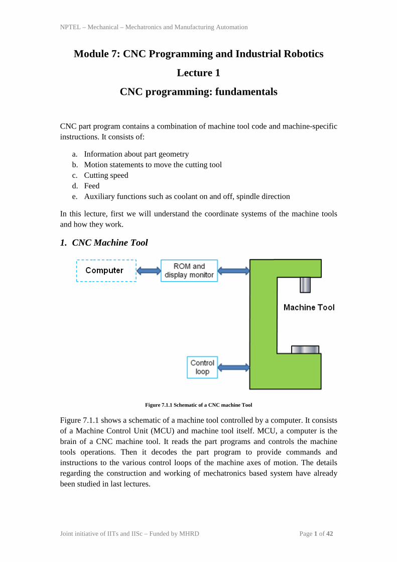
Figure 7.1.1 Schematic of a CNC machine Tool
Figure 7.1.1 shows a schematic of a machine tool controlled by a computer. It consists of a Machine Control Unit (MCU) and machine tool itself. MCU, a computer is the brain of a CNC machine tool. It reads the part programs and controls the machine tools operations. Then it decodes the part program to provide commands and instructions to the various control loops of the machine axes of motion. The details regarding the construction and working of mechatronics based system have already been studied in last lectures.
NPTEL – Mechanical – Mechatronics and Manufacturing Automation
Joint initiative of IITs and IISc – Funded by MHRD Page 2 of 42
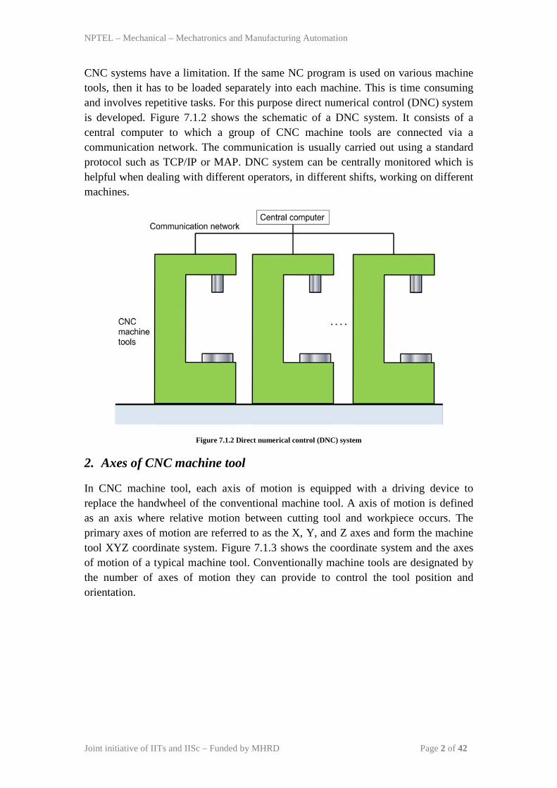
CNC systems have a limitation. If the same NC program is used on various machine tools, then it has to be loaded separately into each machine. This is time consuming and involves repetitive tasks. For this purpose direct numerical control (DNC) system is developed. Figure 7.1.2 shows the schematic of a DNC system. It consists of a central computer to which a group of CNC machine tools are connected via a communication network. The communication is usually carried out using a standard protocol such as TCP/IP or MAP. DNC system can be centrally monitored which is helpful when dealing with different operators, in different shifts, working on different machines.
Figure 7.1.2 Direct numerical control (DNC) system
2. Axes of CNC machine tool
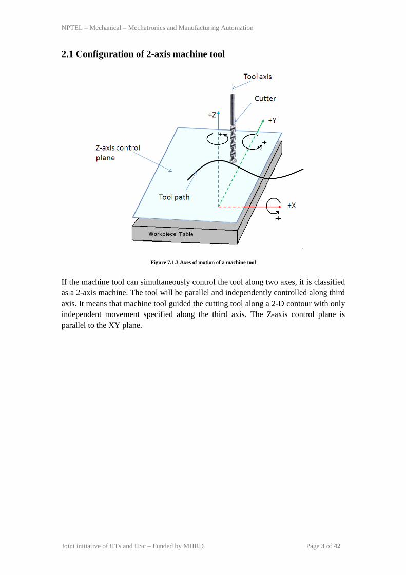
In CNC machine tool, each axis of motion is equipped with a driving device to replace the handwheel of the conventional machine tool. A axis of motion is defined as an axis where relative motion between cutting tool and workpiece occurs. The primary axes of motion are referred to as the X, Y, and Z axes and form the machine tool XYZ coordinate system. Figure 7.1.3 shows the coordinate system and the axes of motion of a typical machine tool. Conventionally machine tools are designated by the number of axes of motion they can provide to control the tool position and orientation.
NPTEL – Mechanical – Mechatronics and Manufacturing Automation
Joint initiative of IITs and IISc – Funded by MHRD Page 3 of 42
2.1 Configuration of 2-axis machine tool
Figure 7.1.3 Axes of motion of a machine tool
If the machine tool can simultaneously control the tool along two axes, it is classified as a 2-axis machine. The tool will be parallel and independently controlled along third axis. It means that machine tool guided the cutting tool along a 2-D contour with only independent movement specified along the third axis. The Z-axis control plane is parallel to the XY plane.
NPTEL – Mechanical – Mechatronics and Manufacturing Automation
Joint initiative of IITs and IISc – Funded by MHRD Page 4 of 42
2.2 Configuration of 2.5-axis machine tool
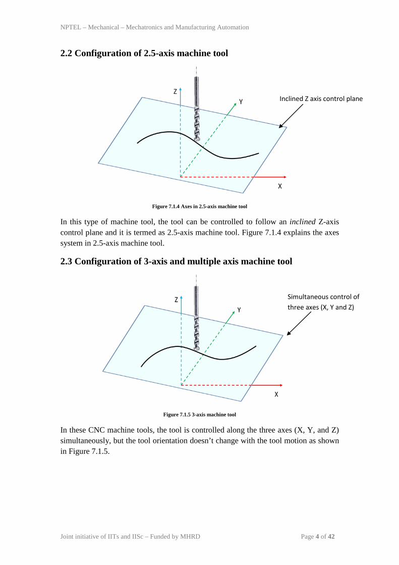
Figure 7.1.4 Axes in 2.5-axis machine tool
In this type of machine tool, the tool can be controlled to follow an inclined Z-axis control plane and it is termed as 2.5-axis machine tool. Figure 7.1.4 explains the axes system in 2.5-axis machine tool.
2.3 Configuration of 3-axis and multiple axis machine tool
Figure 7.1.5 3-axis machine tool
In these CNC machine tools, the tool is controlled along the three axes (X, Y, and Z) simultaneously, but the tool orientation doesn’t change with the tool motion as shown in Figure 7.1.5.
Inclined Z axis control plane
Simultaneous control of three axes (X, Y and Z)
NPTEL – Mechanical – Mechatronics and Manufacturing Automation
Joint initiative of IITs and IISc – Funded by MHRD Page 5 of 42
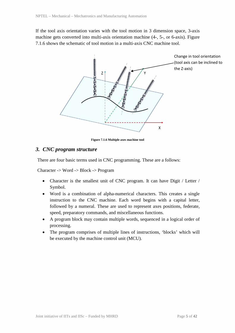
If the tool axis orientation varies with the tool motion in 3 dimension space, 3-axis machine gets converted into multi-axis orientation machine (4-, 5-, or 6-axis). Figure 7.1.6 shows the schematic of tool motion in a multi-axis CNC machine tool.
Figure 7.1.6 Multiple axes machine tool
3. CNC program structure
There are four basic terms used in CNC programming. These are a follows:
Character -> Word -> Block -> Program
• Character is the smallest unit of CNC program. It can have Digit / Letter / Symbol.
• Word is a combination of alpha-numerical characters. This creates a single instruction to the CNC machine. Each word begins with a capital letter, followed by a numeral. These are used to represent axes positions, federate, speed, preparatory commands, and miscellaneous functions.
• A program block may contain multiple words, sequenced in a logical order of processing.
• The program comprises of multiple lines of instructions, ‘blocks’ which will be executed by the machine control unit (MCU).
Change in tool orientation (tool axis can be inclined to the Z-axis)
NPTEL – Mechanical – Mechatronics and Manufacturing Automation
Joint initiative of IITs and IISc – Funded by MHRD Page 6 of 42
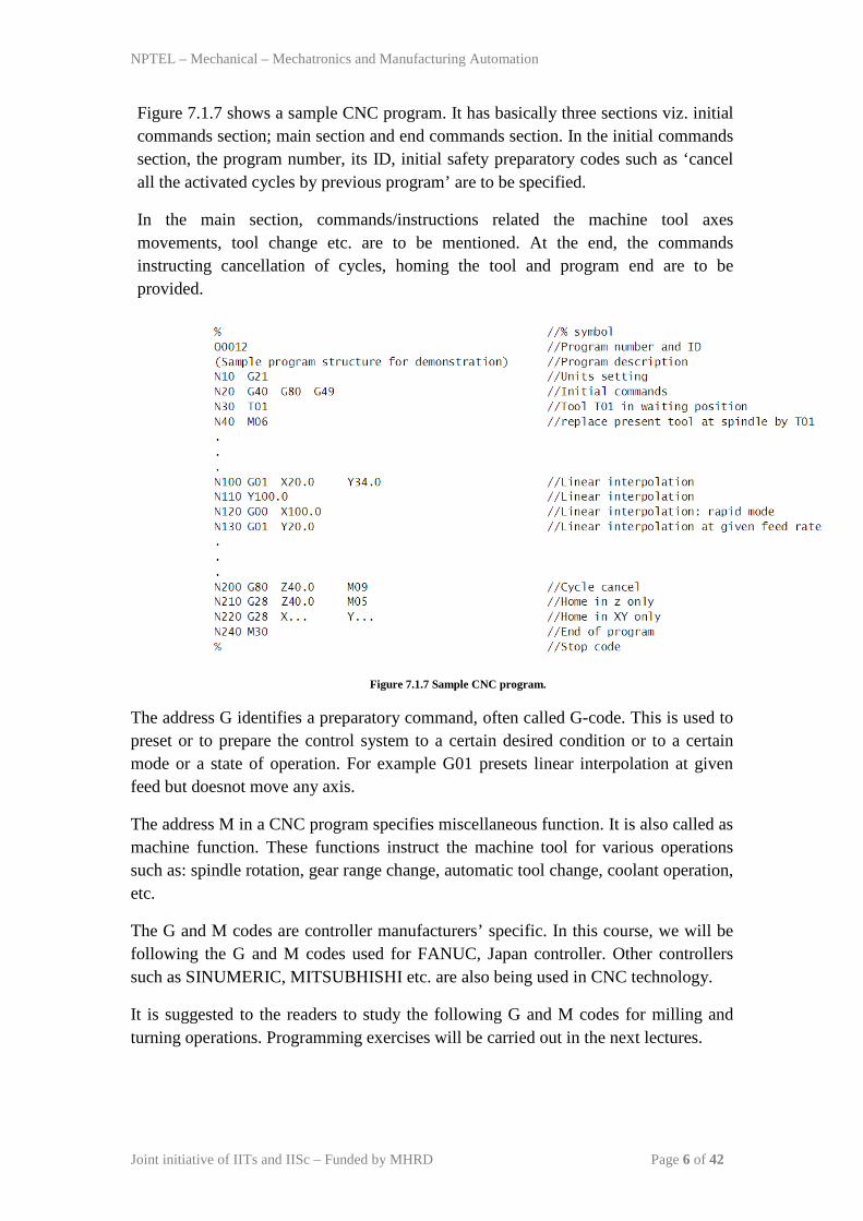
Figure 7.1.7 shows a sample CNC program. It has basically three sections viz. initial commands section; main section and end commands section. In the initial commands section, the program number, its ID, initial safety preparatory codes such as ‘cancel all the activated cycles by previous program’ are to be specified.
In the main section, commands/instructions related the machine tool axes movements, tool change etc. are to be mentioned. At the end, the commands instructing cancellation of cycles, homing the tool and program end are to be provided.
Figure 7.1.7 Sample CNC program.
The address G identifies a preparatory command, often called G-code. This is used to preset or to prepare the control system to a certain desired condition or to a certain mode or a state of operation. For example G01 presets linear interpolation at given feed but doesnot move any axis.
The address M in a CNC program specifies miscellaneous function. It is also called as machine function. These functions instruct the machine tool for various operations such as: spindle rotation, gear range change, automatic tool change, coolant operation, etc.
The G and M codes are controller manufacturers’ specific. In this course, we will be following the G and M codes used for FANUC, Japan controller. Other controllers such as SINUMERIC, MITSUBHISHI etc. are also being used in CNC technology.
It is suggested to the readers to study the following G and M codes for milling and turning operations. Programming exercises will be carried out in the next lectures.
NPTEL – Mechanical – Mechatronics and Manufacturing Automation
Joint initiative of IITs and IISc – Funded by MHRD Page 7 of 42
Module 7: CNC Programming and Industrial Robotics
Lecture 2
CNC programming: Drilling operations In this lecture we will learn how to write a part program to manufacture drilled holes. Let us take an exercise and study the various preparatory and miscellaneous functions associated with the problem.
Exercise:
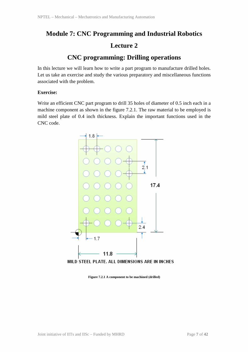
Write an efficient CNC part program to drill 35 holes of diameter of 0.5 inch each in a machine component as shown in the figure 7.2.1. The raw material to be employed is mild steel plate of 0.4 inch thickness. Explain the important functions used in the CNC code.
Figure 7.2.1 A component to be machined (drilled)
NPTEL – Mechanical – Mechatronics and Manufacturing Automation
Joint initiative of IITs and IISc – Funded by MHRD Page 8 of 42
Solution:
Based on the G and M code discussed in the last lecture, the CNC part program for FANUC controller can be written as follows:
Block 1 % 2 O0001 3 N10 G20 4 N20 G17 G40 G80 G49 G90 5 N30 G92 X… Y… Z… 6 N40 M06 T01 7 N50 G00 X1.7 Y2.4 S900 M03 8 N60 G43 Z1.0 H01 M08 9 N70 G99 G81 R0.1 Z-0.4 F3.0
10 N80 G91 Y2.1 K6 (L6) 11 N90 X1.8 12 N100 Y-2.1 K6 (L6) 13 N110 X1.8 14 N120 Y2.1 K6 (L6) 15 N130 X1.8 16 N140 Y-2.1 K6 (L6) 17 N150 X1.8 18 N160 Y2.1 K6 (L6) 19 N170 G90 G80 M09 20 N180 G28 Z10 M05 21 N190 G28 X0 Y0 22 N200 M30 23 %
Let us now see the meaning and significance of each block of the program.
Block 1:
It indicates the start of the program.
Block 2:
It specifies the program number and ID. It is usually a alpha-numerical code and always start with an alphabet ‘O’.
Block 3:
It sets the entry of dimensional units in Imperial format.
Block 4:
G17: It selects the plane of operation as X-Y plane
NPTEL – Mechanical – Mechatronics and Manufacturing Automation
Joint initiative of IITs and IISc – Funded by MHRD Page 9 of 42
G40, G80, G49 are used to cancel all usual cycle that might have left in on-mode during the execution of last CNC code.
G90 selects the method of specifying dimensions between features as ‘absolute’.
Block 5:
It sets the program zero on the work part. There are three major environments in programming that require an established mathematical relationship.
Machine: machine tool and control system
Part: Workpiece + Drawing + material
Tool: Holder + Cutting tool
Machine zero point:
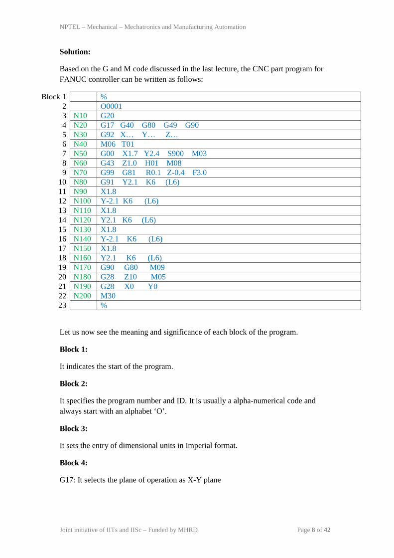
It is also called as home position or machine reference point. It is the origin of a machine coordinate system. On all CNC machines, machine zero is located at the positive end of each axis travel range. Figure 7.2.2 shows the machining volume and various planes. The machine reference point is located at the end of positive ranges of X, Y and Z axes. Figure 7.2.3 and 7.2.4 provide the clear views of the machine reference point. Machine control unit (MCU) understands the dimensions provided with respect to the machine reference point. But the programmer is providing the dimensions on the drawings based on the local coordinate system i.e. part coordinate system.
Figure 7.2.2 machining volume and machine reference point
NPTEL – Mechanical – Mechatronics and Manufacturing Automation
Joint initiative of IITs and IISc – Funded by MHRD Page 10 of 42
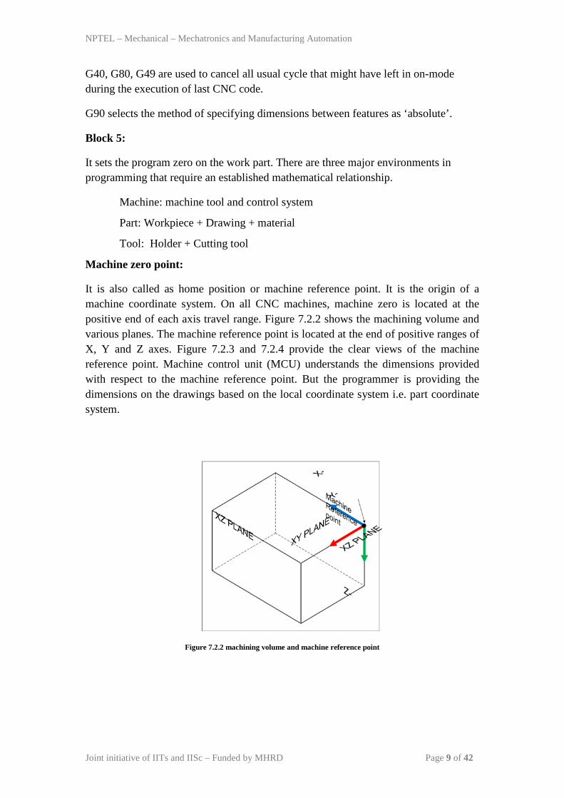
Figure 7.2.3 Top view of a vertical machine as viewed towards the table
Figure 7.2.4 Front view of a vertical machine as viewed from front
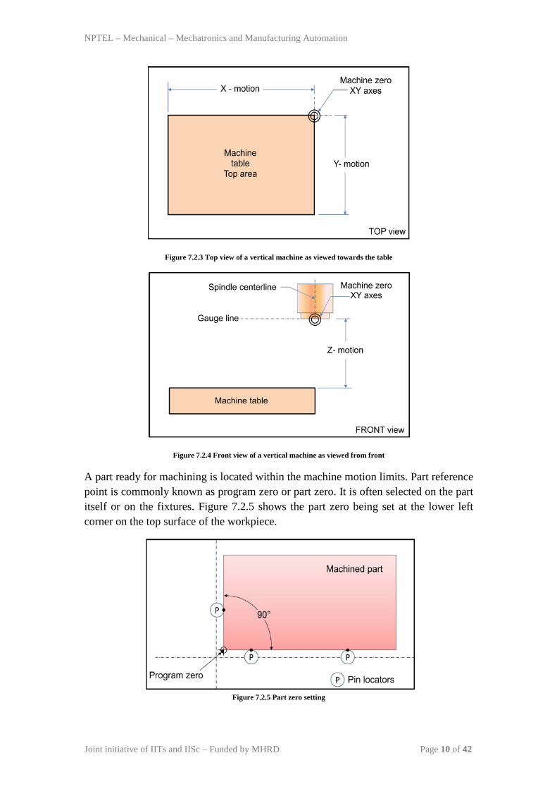
A part ready for machining is located within the machine motion limits. Part reference point is commonly known as program zero or part zero. It is often selected on the part itself or on the fixtures. Figure 7.2.5 shows the part zero being set at the lower left corner on the top surface of the workpiece.
Figure 7.2.5 Part zero setting
NPTEL – Mechanical – Mechatronics and Manufacturing Automation
Joint initiative of IITs and IISc – Funded by MHRD Page 11 of 42
The location coordinates of the program zero with respect to the machine reference zero must be communicated with the MCU so that the MCU will convert the part program in to required signals to control the machine tool. This can be achieved by using a Preparatory code ‘G92’. The syntax of G92 is as follows:
G92 X… Y… Z…
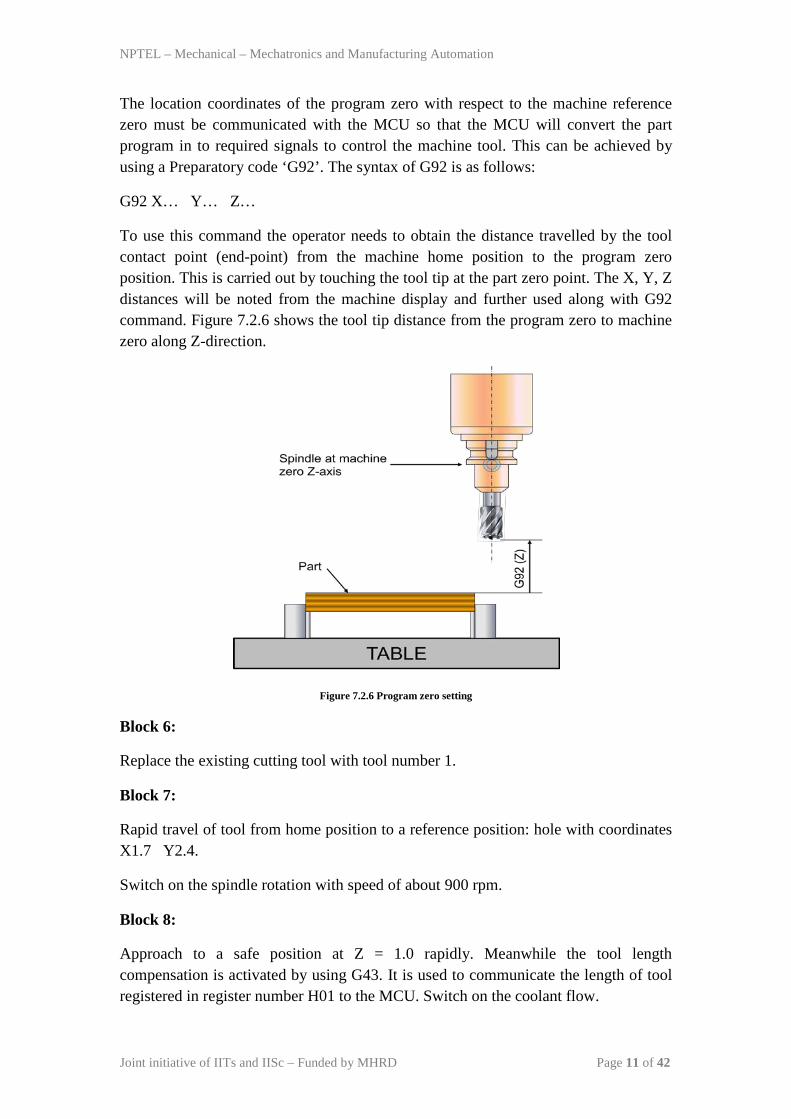
To use this command the operator needs to obtain the distance travelled by the tool contact point (end-point) from the machine home position to the program zero position. This is carried out by touching the tool tip at the part zero point. The X, Y, Z distances will be noted from the machine display and further used along with G92 command. Figure 7.2.6 shows the tool tip distance from the program zero to machine zero along Z-direction.
Figure 7.2.6 Program zero setting
Block 6:
Replace the existing cutting tool with tool number 1.
Block 7:
Rapid travel of tool from home position to a reference position: hole with coordinates X1.7 Y2.4.
Switch on the spindle rotation with speed of about 900 rpm.
Block 8:
Approach to a safe position at Z = 1.0 rapidly. Meanwhile the tool length compensation is activated by using G43. It is used to communicate the length of tool registered in register number H01 to the MCU. Switch on the coolant flow.
NPTEL – Mechanical – Mechatronics and Manufacturing Automation
Joint initiative of IITs and IISc – Funded by MHRD Page 12 of 42
Block 9:
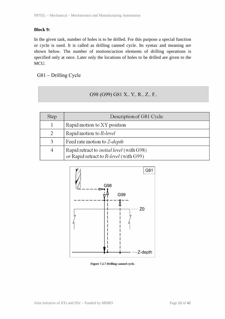
In the given task, number of holes is to be drilled. For this purpose a special function or cycle is used. It is called as drilling canned cycle. Its syntax and meaning are shown below. The number of motions/action elements of drilling operations is specified only at once. Later only the locations of holes to be drilled are given to the MCU.
Figure 7.2.7 Drilling canned cycle.
NPTEL – Mechanical – Mechatronics and Manufacturing Automation
Joint initiative of IITs and IISc – Funded by MHRD Page 13 of 42
Block 10:
It suggests the distance of next location of the hole. It is also suggested to carry out the same drilling operation 6 times along the Y-axis with an increment of 2.1.
Block 11:
Drill the hole at increment of 1.8 along X-direction.
Block 12:
Carry out the drilling operation 6 times along the Y-axis with decrement of 2.1.
Block 13:
Drill the hole at increment of 1.8 along X-direction.
Block 14:
Carry out the drilling operation 6 times along the Y-axis with increment of 2.1.
Block 15:
Drill the hole at increment of 1.8 along X-direction.
Block 16:
Carry out the drilling operation 6 times along the Y-axis with decrement of 2.1.
Block 17:
Drill the hole at increment of 1.8 along X-direction.
Block 18:
Carry out the drilling operation 6 times along the Y-axis with increment of 2.1.
Block 19:
Cancel the canned cycle and switch off the coolant flow.
Block 20:
Stop the spindle and go to safe position along Z direction at 0.0.
Block 21:
Go to home position via X= 0 and Y=0.
Block 22:
Stop the program from execution.

NPTEL – Mechanical – Mechatronics and Manufacturing Automation
Joint initiative of IITs and IISc – Funded by MHRD Page 14 of 42
Block 23:
End the program.
NPTEL – Mechanical – Mechatronics and Manufacturing Automation
Joint initiative of IITs and IISc – Funded by MHRD Page 15 of 42
Module 7: CNC Programming and Industrial Robotics
Lecture 3
CNC programming: Milling operations
In this lecture we will learn to write part program for contouring operations being carried out on a CNC milling machine. Let us take an exercise:
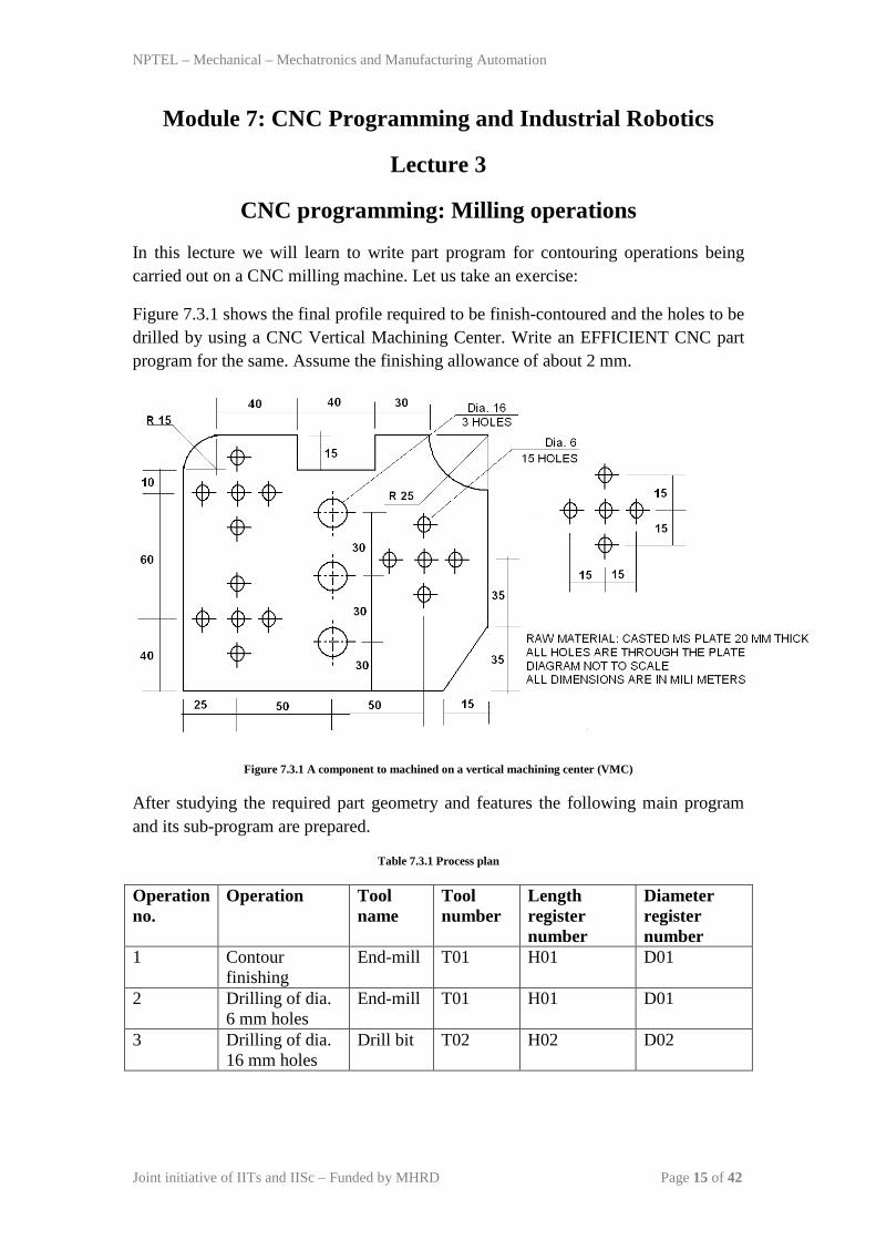
Figure 7.3.1 shows the final profile required to be finish-contoured and the holes to be drilled by using a CNC Vertical Machining Center. Write an EFFICIENT CNC part program for the same. Assume the finishing allowance of about 2 mm.
Figure 7.3.1 A component to machined on a vertical machining center (VMC)
After studying the required part geometry and features the following main program and its sub-program are prepared.
Table 7.3.1 Process plan
Operation no.
Operation Tool name
Tool number
Length register number
Diameter register number
1 Contour finishing
End-mill T01 H01 D01
2 Drilling of dia. 6 mm holes
End-mill T01 H01 D01
3 Drilling of dia. 16 mm holes
Drill bit T02 H02 D02
NPTEL – Mechanical – Mechatronics and Manufacturing Automation
Joint initiative of IITs and IISc – Funded by MHRD Page 16 of 42
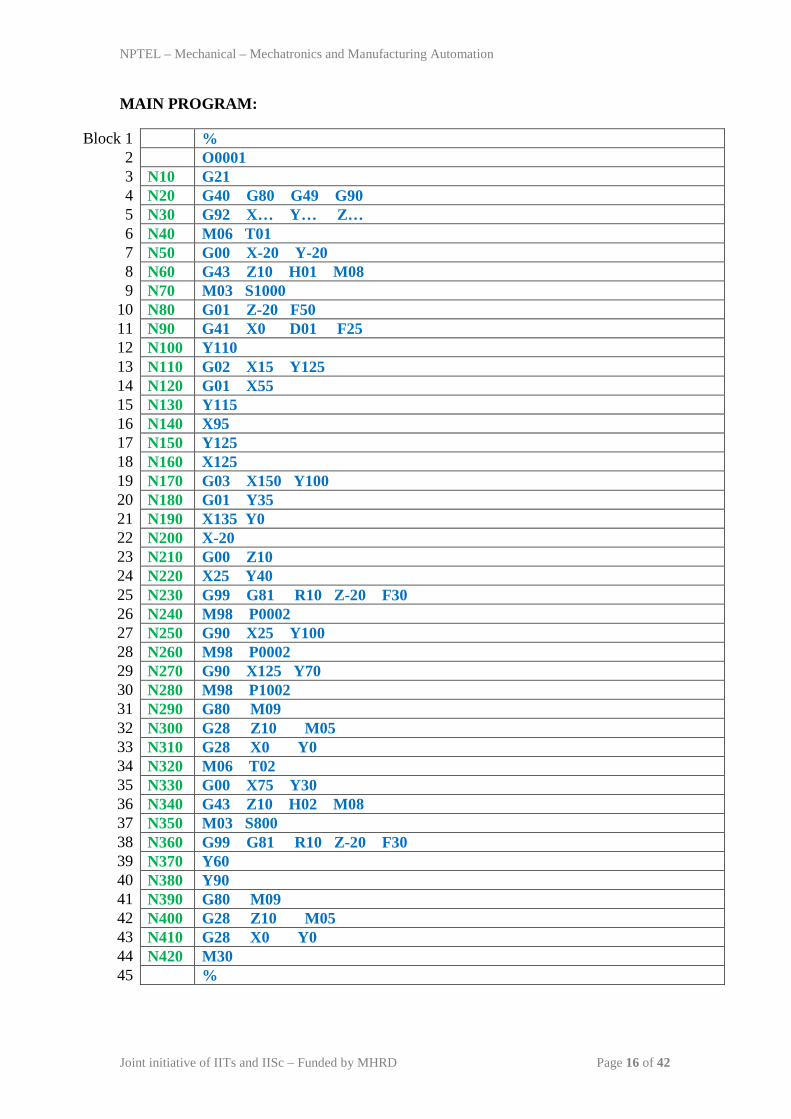
MAIN PROGRAM:
Block 1 % 2 O0001 3 N10 G21 4 N20 G40 G80 G49 G90 5 N30 G92 X… Y… Z… 6 N40 M06 T01 7 N50 G00 X-20 Y-20 8 N60 G43 Z10 H01 M08 9 N70 M03 S1000
10 N80 G01 Z-20 F50 11 N90 G41 X0 D01 F25 12 N100 Y110 13 N110 G02 X15 Y125 14 N120 G01 X55 15 N130 Y115 16 N140 X95 17 N150 Y125 18 N160 X125 19 N170 G03 X150 Y100 20 N180 G01 Y35 21 N190 X135 Y0 22 N200 X-20 23 N210 G00 Z10 24 N220 X25 Y40 25 N230 G99 G81 R10 Z-20 F30 26 N240 M98 P0002 27 N250 G90 X25 Y100 28 N260 M98 P0002 29 N270 G90 X125 Y70 30 N280 M98 P1002 31 N290 G80 M09 32 N300 G28 Z10 M05 33 N310 G28 X0 Y0 34 N320 M06 T02 35 N330 G00 X75 Y30 36 N340 G43 Z10 H02 M08 37 N350 M03 S800 38 N360 G99 G81 R10 Z-20 F30 39 N370 Y60 40 N380 Y90 41 N390 G80 M09 42 N400 G28 Z10 M05 43 N410 G28 X0 Y0 44 N420 M30 45 %
NPTEL – Mechanical – Mechatronics and Manufacturing Automation
Joint initiative of IITs and IISc – Funded by MHRD Page 17 of 42
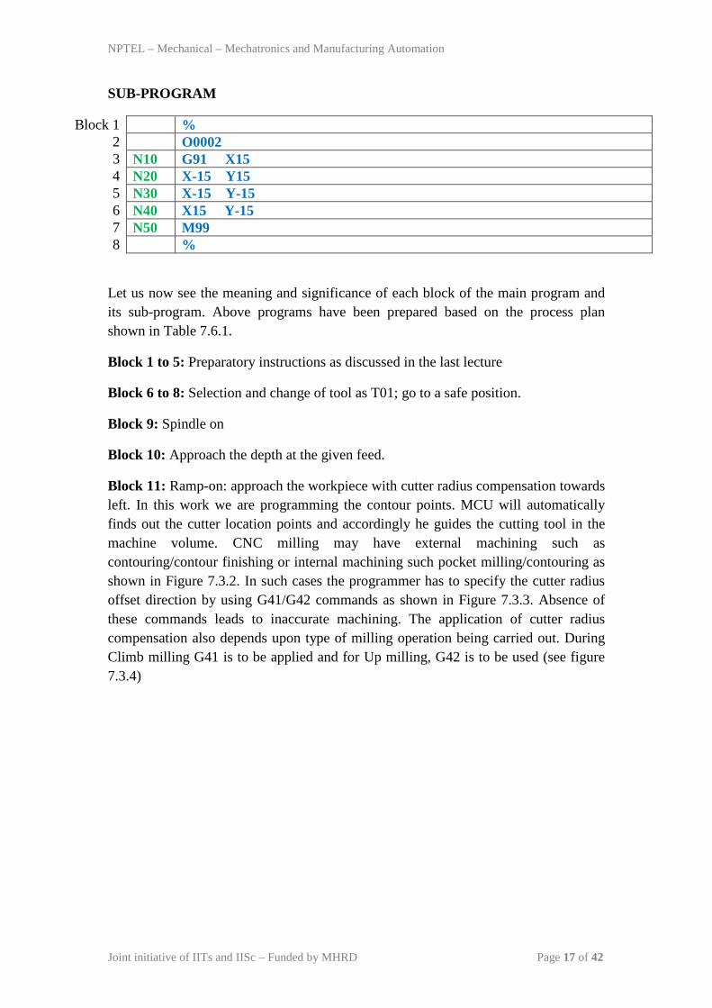
SUB-PROGRAM
Block 1 % 2 O0002 3 N10 G91 X15 4 N20 X-15 Y15 5 N30 X-15 Y-15 6 N40 X15 Y-15 7 N50 M99 8 %
Let us now see the meaning and significance of each block of the main program and its sub-program. Above programs have been prepared based on the process plan shown in Table 7.6.1.
Block 1 to 5: Preparatory instructions as discussed in the last lecture
Block 6 to 8: Selection and change of tool as T01; go to a safe position.
Block 9: Spindle on
Block 10: Approach the depth at the given feed.
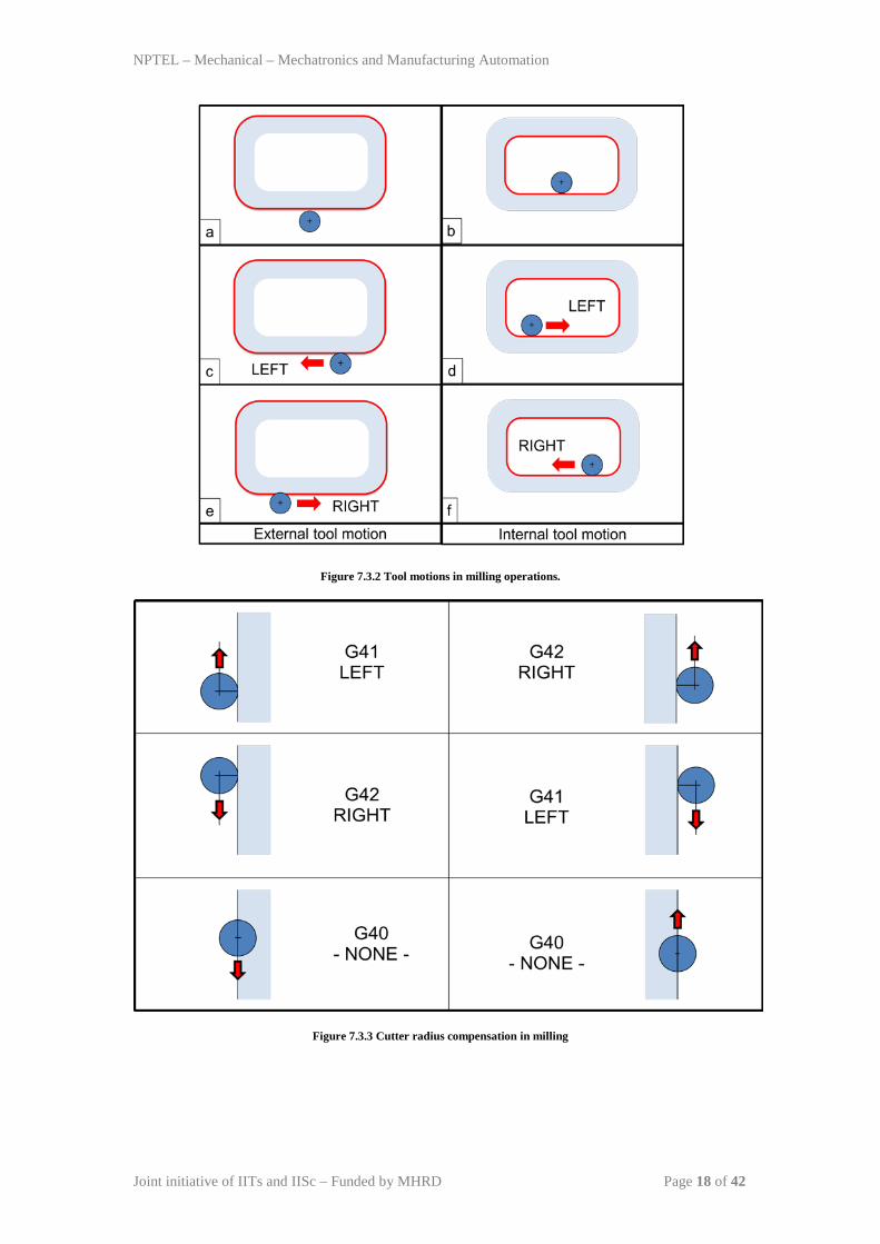
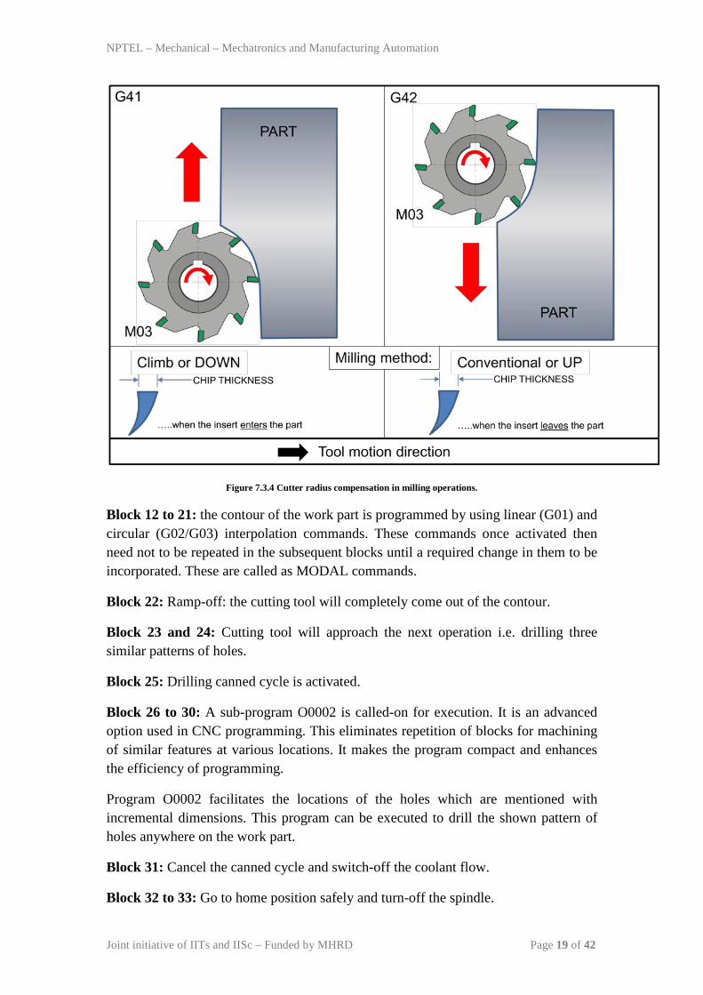
Block 11: Ramp-on: approach the workpiece with cutter radius compensation towards left. In this work we are programming the contour points. MCU will automatically finds out the cutter location points and accordingly he guides the cutting tool in the machine volume. CNC milling may have external machining such as contouring/contour finishing or internal machining such pocket milling/contouring as shown in Figure 7.3.2. In such cases the programmer has to specify the cutter radius offset direction by using G41/G42 commands as shown in Figure 7.3.3. Absence of these commands leads to inaccurate machining. The application of cutter radius compensation also depends upon type of milling operation being carried out. During Climb milling G41 is to be applied and for Up milling, G42 is to be used (see figure 7.3.4)
NPTEL – Mechanical – Mechatronics and Manufacturing Automation
Joint initiative of IITs and IISc – Funded by MHRD Page 18 of 42
Figure 7.3.2 Tool motions in milling operations.
Figure 7.3.3 Cutter radius compensation in milling
NPTEL – Mechanical – Mechatronics and Manufacturing Automation
Joint initiative of IITs and IISc – Funded by MHRD Page 19 of 42
Figure 7.3.4 Cutter radius compensation in milling operations.
Block 12 to 21: the contour of the work part is programmed by using linear (G01) and circular (G02/G03) interpolation commands. These commands once activated then need not to be repeated in the subsequent blocks until a required change in them to be incorporated. These are called as MODAL commands.
Block 22: Ramp-off: the cutting tool will completely come out of the contour.
Block 23 and 24: Cutting tool will approach the next operation i.e. drilling three similar patterns of holes.
Block 25: Drilling canned cycle is activated.
Block 26 to 30: A sub-program O0002 is called-on for execution. It is an advanced option used in CNC programming. This eliminates repetition of blocks for machining of similar features at various locations. It makes the program compact and enhances the efficiency of programming.
Program O0002 facilitates the locations of the holes which are mentioned with incremental dimensions. This program can be executed to drill the shown pattern of holes anywhere on the work part.
Block 31: Cancel the canned cycle and switch-off the coolant flow.
Block 32 to 33: Go to home position safely and turn-off the spindle.

NPTEL – Mechanical – Mechatronics and Manufacturing Automation
Joint initiative of IITs and IISc – Funded by MHRD Page 20 of 42
Block 34 to 37: Make the Tool 2 ready for drilling dia. 16 mm hole; change the tool; and turn-on the spindle as well as coolant.
Block 38 to 40: Execute the drilling canned cycle at three locations.
Block 41 to 45: Send the cutting tool to home position safely; switch-off the spindle as well as coolant; and stop the program.
NPTEL – Mechanical – Mechatronics and Manufacturing Automation
Joint initiative of IITs and IISc – Funded by MHRD Page 21 of 42
Module 7: CNC Programming and Industrial Robotics
Lecture 4
CNC programming: Turning operations
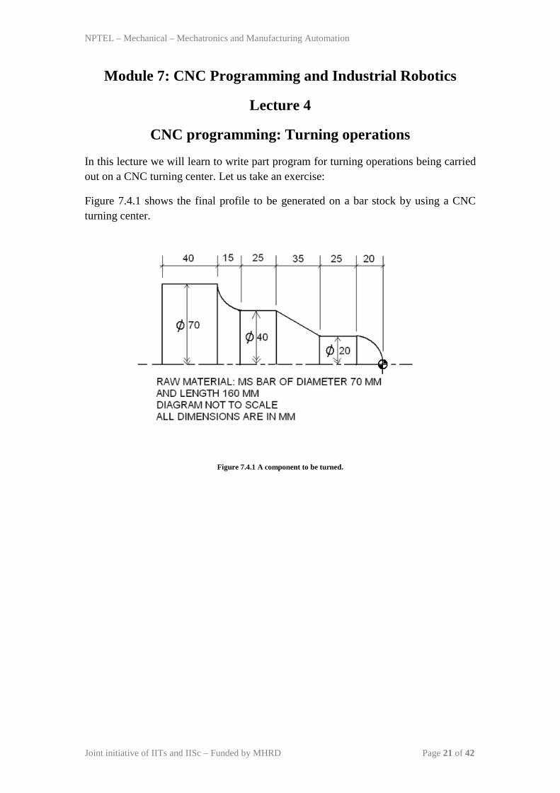
In this lecture we will learn to write part program for turning operations being carried out on a CNC turning center. Let us take an exercise:
Figure 7.4.1 shows the final profile to be generated on a bar stock by using a CNC turning center.
Figure 7.4.1 A component to be turned.
NPTEL – Mechanical – Mechatronics and Manufacturing Automation
Joint initiative of IITs and IISc – Funded by MHRD Page 22 of 42
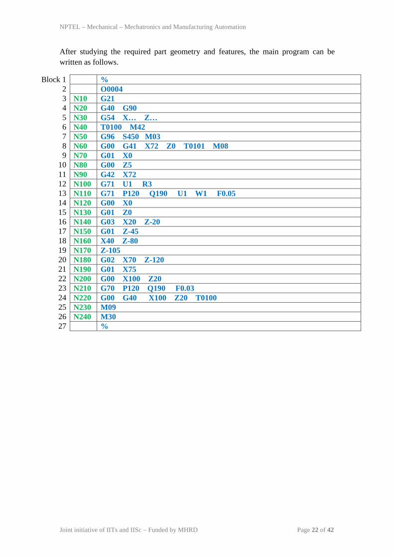
After studying the required part geometry and features, the main program can be written as follows.
Block 1 % 2 O0004 3 N10 G21 4 N20 G40 G90 5 N30 G54 X… Z… 6 N40 T0100 M42 7 N50 G96 S450 M03 8 N60 G00 G41 X72 Z0 T0101 M08 9 N70 G01 X0
10 N80 G00 Z5 11 N90 G42 X72 12 N100 G71 U1 R3 13 N110 G71 P120 Q190 U1 W1 F0.05 14 N120 G00 X0 15 N130 G01 Z0 16 N140 G03 X20 Z-20 17 N150 G01 Z-45 18 N160 X40 Z-80 19 N170 Z-105 20 N180 G02 X70 Z-120 21 N190 G01 X75 22 N200 G00 X100 Z20 23 N210 G70 P120 Q190 F0.03 24 N220 G00 G40 X100 Z20 T0100 25 N230 M09 26 N240 M30 27 %
NPTEL – Mechanical – Mechatronics and Manufacturing Automation
Joint initiative of IITs and IISc – Funded by MHRD Page 23 of 42
Let us now see the meaning and significance of each block of the program.
Block 1 to 4: Preparatory functions and commands.
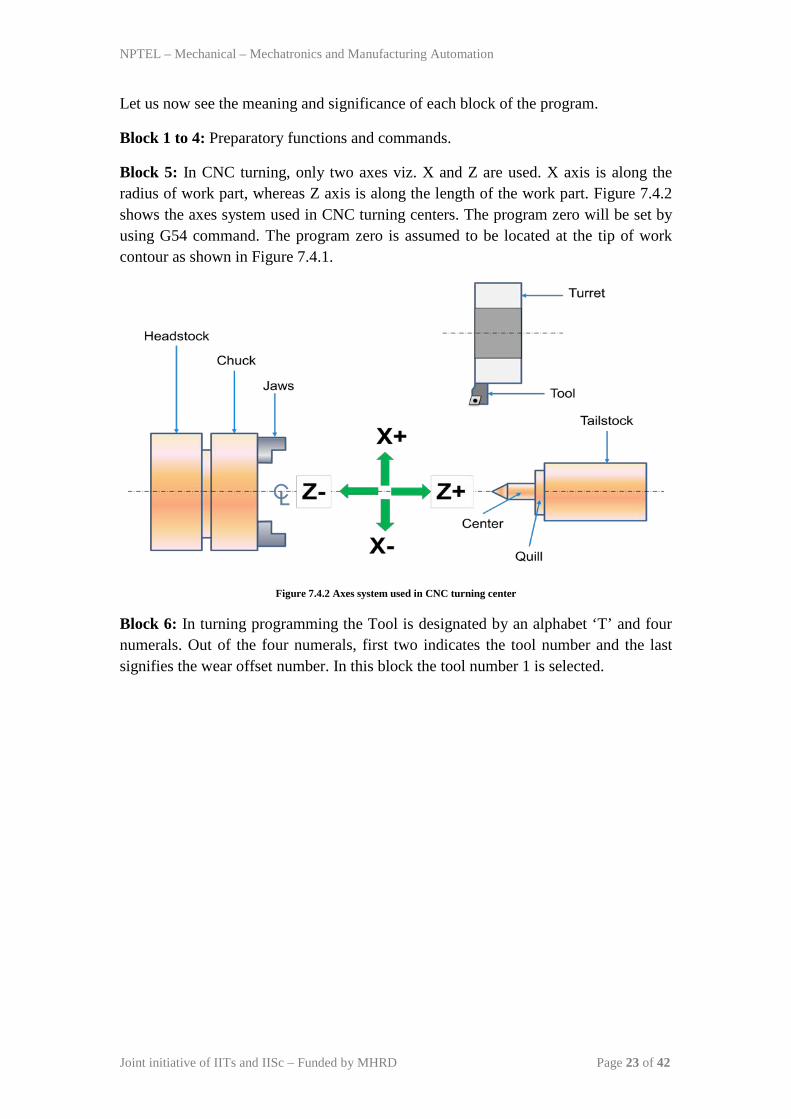
Block 5: In CNC turning, only two axes viz. X and Z are used. X axis is along the radius of work part, whereas Z axis is along the length of the work part. Figure 7.4.2 shows the axes system used in CNC turning centers. The program zero will be set by using G54 command. The program zero is assumed to be located at the tip of work contour as shown in Figure 7.4.1.
Figure 7.4.2 Axes system used in CNC turning center
Block 6: In turning programming the Tool is designated by an alphabet ‘T’ and four numerals. Out of the four numerals, first two indicates the tool number and the last signifies the wear offset number. In this block the tool number 1 is selected.
NPTEL – Mechanical – Mechatronics and Manufacturing Automation
Joint initiative of IITs and IISc – Funded by MHRD Page 24 of 42
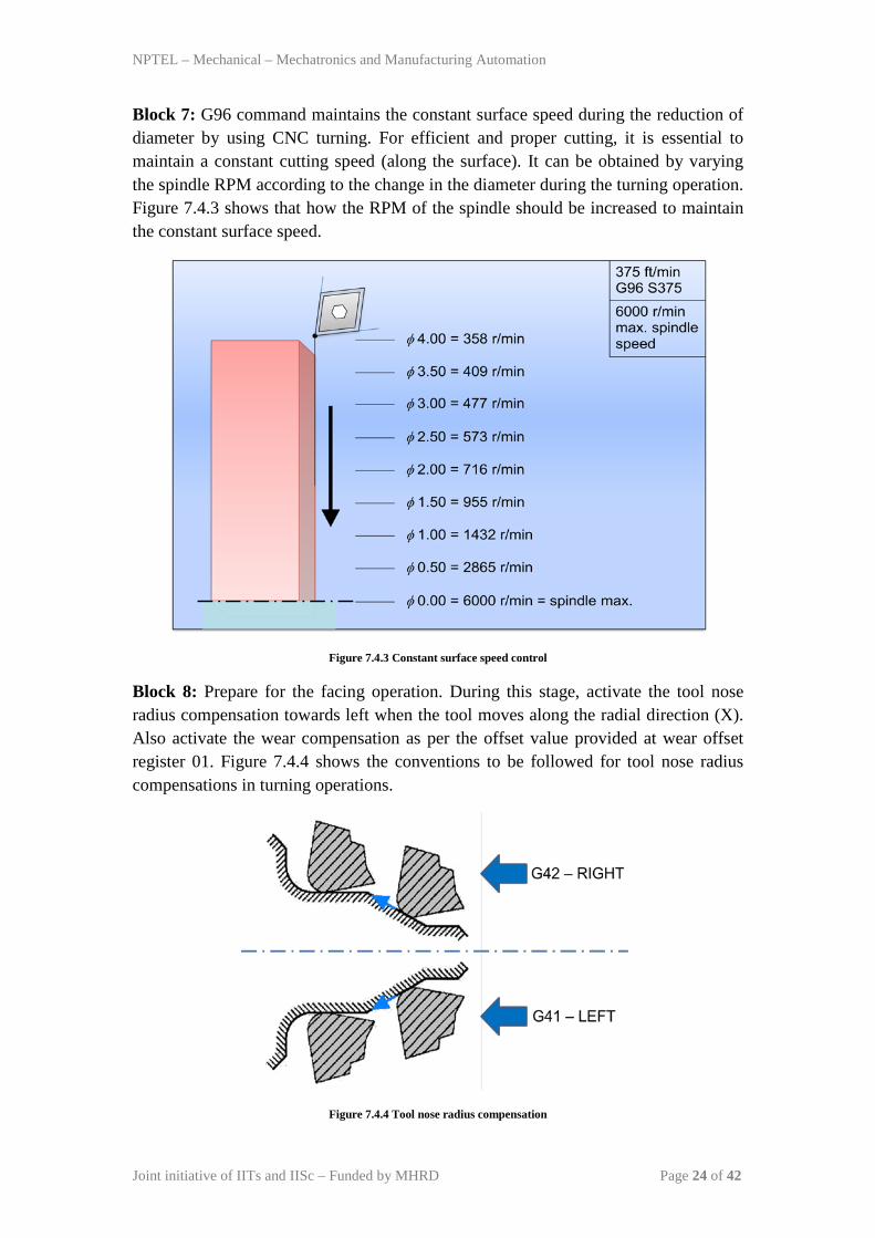
Block 7: G96 command maintains the constant surface speed during the reduction of diameter by using CNC turning. For efficient and proper cutting, it is essential to maintain a constant cutting speed (along the surface). It can be obtained by varying the spindle RPM according to the change in the diameter during the turning operation. Figure 7.4.3 shows that how the RPM of the spindle should be increased to maintain the constant surface speed.
Figure 7.4.3 Constant surface speed control
Block 8: Prepare for the facing operation. During this stage, activate the tool nose radius compensation towards left when the tool moves along the radial direction (X). Also activate the wear compensation as per the offset value provided at wear offset register 01. Figure 7.4.4 shows the conventions to be followed for tool nose radius compensations in turning operations.
Figure 7.4.4 Tool nose radius compensation
NPTEL – Mechanical – Mechatronics and Manufacturing Automation
Joint initiative of IITs and IISc – Funded by MHRD Page 25 of 42
Block 9: Carry out the facing operation.
Block 10 and 11: Go to safe position X 72 and Z 5. During this movement activate the tool nose radius compensation towards right side of the contour.
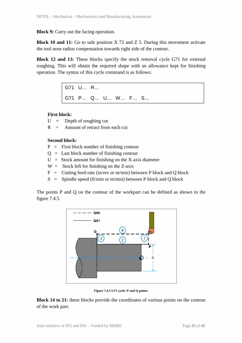
Block 12 and 13: These blocks specify the stock removal cycle G71 for external roughing. This will obtain the required shape with an allowance kept for finishing operation. The syntax of this cycle command is as follows:
First block: U = Depth of roughing cut R = Amount of retract from each cut Second block: P = First block number of finishing contour Q = Last block number of finishing contour U = Stock amount for finishing on the X-axis diameter W = Stock left for finishing on the Z-axis F = Cutting feed-rate (in/rev or m/min) between P block and Q block S = Spindle speed (ft/min or m/min) between P block and Q block
The points P and Q on the contour of the workpart can be defined as shown in the figure 7.4.5
Figure 7.4.5 G71 cycle: P and Q points.
Block 14 to 21: these blocks provide the coordinates of various points on the contour of the work part.
G71 U… R…
G71 P… Q… U… W… F… S…
NPTEL – Mechanical – Mechatronics and Manufacturing Automation
Joint initiative of IITs and IISc – Funded by MHRD Page 26 of 42
Block 22: Go to a safe position.
Block 23: In this block the finishing cycle G70 will be executed. The syntax for this cycle is as follows:
where, P = First block number of the finishing contour Q = Last block number of the finishing contour F = Cutting feed rate (in/rev or mm/rev) S = Spindle speed (ft/min or m/min) Block 24 to 27: Go to safe potion (home); cancel all activated cycles and stops the program.
G70 P… Q… F… S…
NPTEL – Mechanical – Mechatronics and Manufacturing Automation
Joint initiative of IITs and IISc – Funded by MHRD Page 27 of 42
Module 7: CNC Programming and Industrial Robotics
Lecture 5
Industrial robotics-1
1. Introduction
An industrial robot is a general-purpose, programmable machine. It possesses some anthropomorphic characteristics, i.e. human-like characteristics that resemble the human physical structure. The robots also respond to sensory signals in a manner that is similar to humans. Anthropomorphic characteristics such as mechanical arms are used for various industry tasks. Sensory perceptive devices such as sensors allow the robots to communicate and interact with other machines and to take simple decisions. The general commercial and technological advantages of robots are listed below:
• Robots are good substitutes to the human beings in hazardous or uncomfortable work environments.
• A robot performs its work cycle with a consistency and repeatability which is difficult for human beings to attain over a long period of continuous working.
• Robots can be reprogrammed. When the production run of the current task is completed, a robot can be reprogrammed and equipped with the necessary tooling to perform an altogether different task.
• Robots can be connected to the computer systems and other robotics systems. Nowadays robots can be controlled with wire-less control technologies. This has enhanced the productivity and efficiency of automation industry.
2. Robot anatomy and related attributes
2.1 Joints and Links
The manipulator of an industrial robot consists of a series of joints and links. Robot anatomy deals with the study of different joints and links and other aspects of the manipulator’s physical construction. A robotic joint provides relative motion between two links of the robot. Each joint, or axis, provides a certain degree-of-freedom (dof) of motion. In most of the cases, only one degree-of-freedom is associated with each joint. Therefore the robot’s complexity can be classified according to the total number of degrees-of-freedom they possess.
Each joint is connected to two links, an input link and an output link. Joint provides controlled relative movement between the input link and output link. A robotic link is the rigid component of the robot manipulator. Most of the robots
NPTEL – Mechanical – Mechatronics and Manufacturing Automation
Joint initiative of IITs and IISc – Funded by MHRD Page 28 of 42
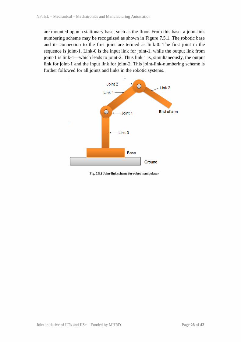
are mounted upon a stationary base, such as the floor. From this base, a joint-link numbering scheme may be recognized as shown in Figure 7.5.1. The robotic base and its connection to the first joint are termed as link-0. The first joint in the sequence is joint-1. Link-0 is the input link for joint-1, while the output link from joint-1 is link-1—which leads to joint-2. Thus link 1 is, simultaneously, the output link for joint-1 and the input link for joint-2. This joint-link-numbering scheme is further followed for all joints and links in the robotic systems.
Fig. 7.5.1 Joint-link scheme for robot manipulator
NPTEL – Mechanical – Mechatronics and Manufacturing Automation
Joint initiative of IITs and IISc – Funded by MHRD Page 29 of 42
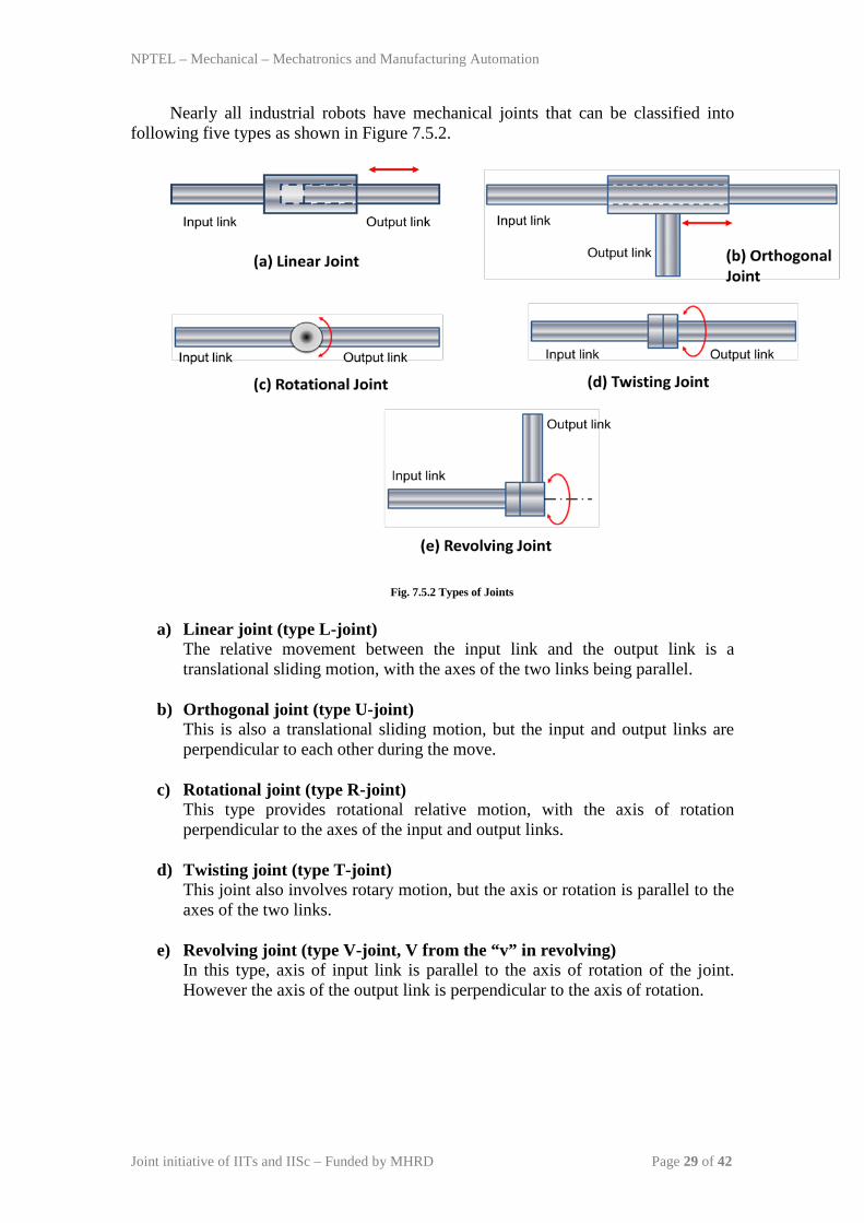
Nearly all industrial robots have mechanical joints that can be classified into following five types as shown in Figure 7.5.2.
Fig. 7.5.2 Types of Joints
a) Linear joint (type L-joint) The relative movement between the input link and the output link is a translational sliding motion, with the axes of the two links being parallel.
b) Orthogonal joint (type U-joint)
This is also a translational sliding motion, but the input and output links are perpendicular to each other during the move.
c) Rotational joint (type R-joint)
This type provides rotational relative motion, with the axis of rotation perpendicular to the axes of the input and output links.
d) Twisting joint (type T-joint)
This joint also involves rotary motion, but the axis or rotation is parallel to the axes of the two links.
e) Revolving joint (type V-joint, V from the “v” in revolving)
In this type, axis of input link is parallel to the axis of rotation of the joint. However the axis of the output link is perpendicular to the axis of rotation.
NPTEL – Mechanical – Mechatronics and Manufacturing Automation
Joint initiative of IITs and IISc – Funded by MHRD Page 30 of 42
2.2 Common Robot Configurations
Basically the robot manipulator has two parts viz. a body-and-arm assembly with three degrees-of-freedom; and a wrist assembly with two or three degrees-of-freedom.
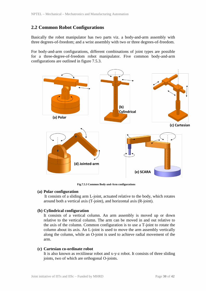
For body-and-arm configurations, different combinations of joint types are possible for a three-degree-of-freedom robot manipulator. Five common body-and-arm configurations are outlined in figure 7.5.3.
Fig.7.5.3 Common Body-and-Arm configurations (a) Polar configuration
It consists of a sliding arm L-joint, actuated relative to the body, which rotates around both a vertical axis (T-joint), and horizontal axis (R-joint).
(b) Cylindrical configuration It consists of a vertical column. An arm assembly is moved up or down relative to the vertical column. The arm can be moved in and out relative to the axis of the column. Common configuration is to use a T-joint to rotate the column about its axis. An L-joint is used to move the arm assembly vertically along the column, while an O-joint is used to achieve radial movement of the arm.
(c) Cartesian co-ordinate robot It is also known as rectilinear robot and x-y-z robot. It consists of three sliding joints, two of which are orthogonal O-joints.
NPTEL – Mechanical – Mechatronics and Manufacturing Automation
Joint initiative of IITs and IISc – Funded by MHRD Page 31 of 42
(d) Jointed-arm robot It is similar to the configuration of a human arm. It consists of a vertical column that swivels about the base using a T-joint. Shoulder joint (R-joint) is located at the top of the column. The output link is an elbow joint (another R joint).
(e) SCARA Its full form is ‘Selective Compliance Assembly Robot Arm’. It is similar in construction to the jointer-arm robot, except the shoulder and elbow rotational axes are vertical. It means that the arm is very rigid in the vertical direction, but compliant in the horizontal direction.
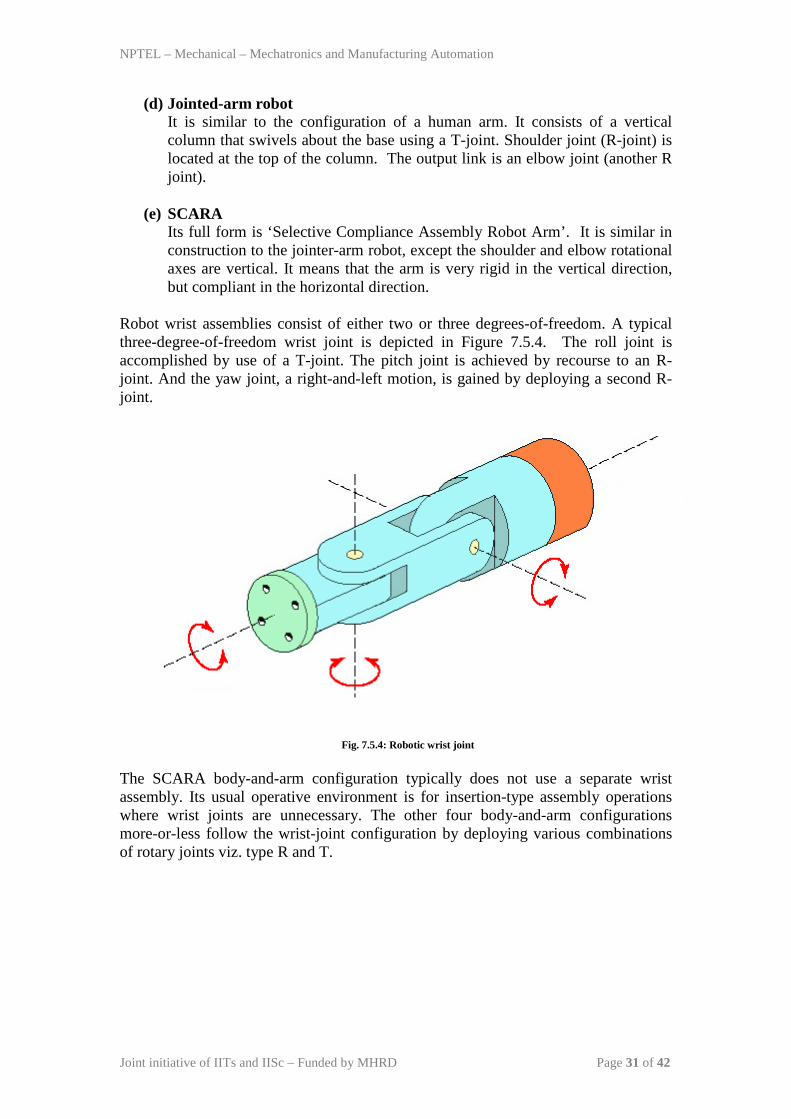
Robot wrist assemblies consist of either two or three degrees-of-freedom. A typical three-degree-of-freedom wrist joint is depicted in Figure 7.5.4. The roll joint is accomplished by use of a T-joint. The pitch joint is achieved by recourse to an R-joint. And the yaw joint, a right-and-left motion, is gained by deploying a second R-joint.
Fig. 7.5.4: Robotic wrist joint
The SCARA body-and-arm configuration typically does not use a separate wrist assembly. Its usual operative environment is for insertion-type assembly operations where wrist joints are unnecessary. The other four body-and-arm configurations more-or-less follow the wrist-joint configuration by deploying various combinations of rotary joints viz. type R and T.
NPTEL – Mechanical – Mechatronics and Manufacturing Automation
Joint initiative of IITs and IISc – Funded by MHRD Page 32 of 42
2.3 Drive systems Basically three types of drive systems are commonly used to actuate robotic joints. These are electric, hydraulic, and pneumatic drives. Electric motors are the prime movers in robots. Servo-motors or steeper motors are widely used in robotics. Hydraulic and pneumatic systems such as piston-cylinder systems, rotary vane actuators are used to accomplish linear motions, and rotary motions of joints respectively. Pneumatic drive is regularly used for smaller, simpler robotic applications; whereas electric and hydraulic drives may be found applications on more sophisticated industrial robots. Due to the advancement in electric motor technology made in recent years, electric drives are generally favored in commercial applications. They also have compatibility to computing systems. Hydraulic systems, although not as flexible as electrical drives, are generally used where larger speeds are required. They are generally employed to carry out heavy duty operations using robots. The combination of drive system, sensors, and feedback control system determines the dynamic response characteristics of the manipulator. Speed in robotic terms refers to the absolute velocity of the manipulator at its end-of-arm. It can be programmed into the work cycle so that different portions of the cycle are carried out at different velocities. Acceleration and deceleration control are also important factors, especially in a confined work envelope. The robot’s ability to control the switching between velocities is a key determinant of the manipulator’s capabilities. Other key determinants are the weight (mass) of the object being manipulated, and the precision that is required to locate and position the object correctly. All of these determinants are gathered under the term ‘speed of response’, which is defined as the time required for the manipulator to move from one point in space to the next. Speed of response influences the robot’s cycle time, which in turn affects the production rate that can be achieved. Stability refers to the amount of overshoot and oscillation that occurs in the robot motion at the end-of-arm as it attempts to move to the next programmed location. More oscillations in the robotic motion lead to less stability in the robotic manipulator. However, greater stability may produce a robotic system with slower response times. Load carrying capacity is also an important factor. It is determined by weight of the gripper used to grasp the objects. A heavy gripper puts a higher load upon the robotic manipulator in addition to the object mass. Commercial robots can carry loads of up to 900 kg, while medium-sized industrial robots may have capacities of up to 45kg.
NPTEL – Mechanical – Mechatronics and Manufacturing Automation
Joint initiative of IITs and IISc – Funded by MHRD Page 33 of 42
Module 7: CNC Programming and Industrial Robotics Lecture 6
Industrial robotics-2 1. Robot Control Systems
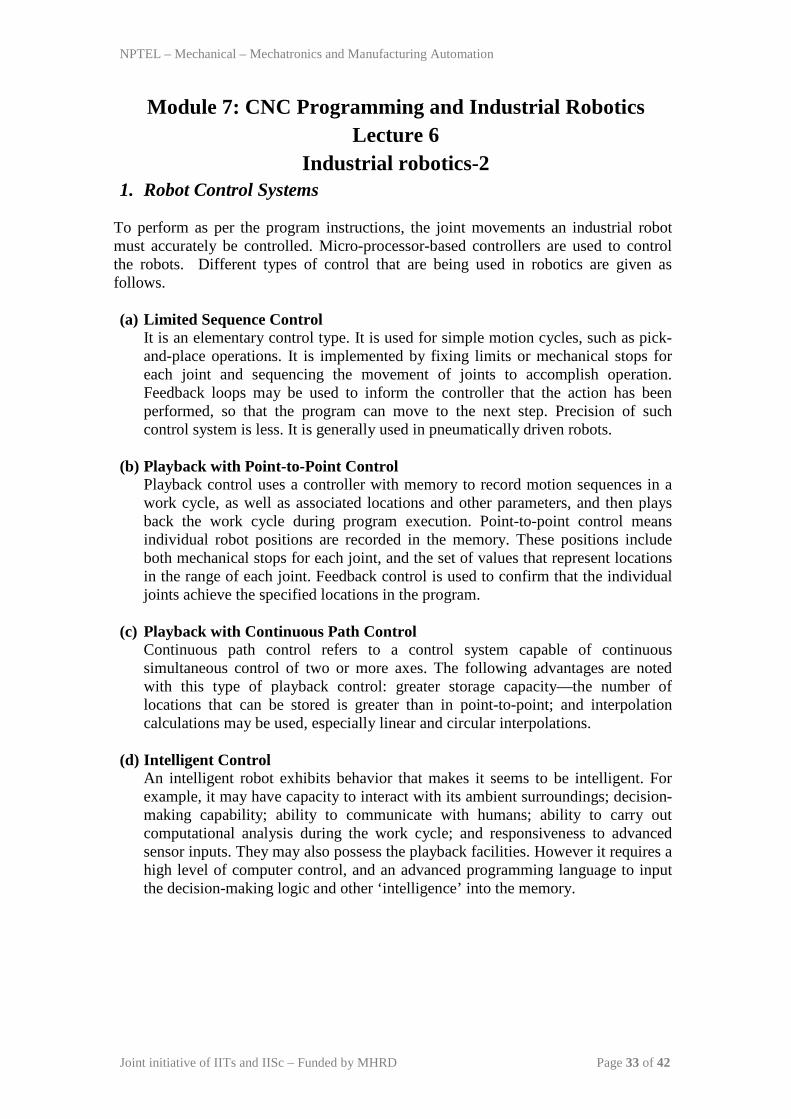
To perform as per the program instructions, the joint movements an industrial robot must accurately be controlled. Micro-processor-based controllers are used to control the robots. Different types of control that are being used in robotics are given as follows.
(a) Limited Sequence Control
It is an elementary control type. It is used for simple motion cycles, such as pick-and-place operations. It is implemented by fixing limits or mechanical stops for each joint and sequencing the movement of joints to accomplish operation. Feedback loops may be used to inform the controller that the action has been performed, so that the program can move to the next step. Precision of such control system is less. It is generally used in pneumatically driven robots.
(b) Playback with Point-to-Point Control Playback control uses a controller with memory to record motion sequences in a work cycle, as well as associated locations and other parameters, and then plays back the work cycle during program execution. Point-to-point control means individual robot positions are recorded in the memory. These positions include both mechanical stops for each joint, and the set of values that represent locations in the range of each joint. Feedback control is used to confirm that the individual joints achieve the specified locations in the program.
(c) Playback with Continuous Path Control Continuous path control refers to a control system capable of continuous simultaneous control of two or more axes. The following advantages are noted with this type of playback control: greater storage capacity—the number of locations that can be stored is greater than in point-to-point; and interpolation calculations may be used, especially linear and circular interpolations.
(d) Intelligent Control An intelligent robot exhibits behavior that makes it seems to be intelligent. For example, it may have capacity to interact with its ambient surroundings; decision-making capability; ability to communicate with humans; ability to carry out computational analysis during the work cycle; and responsiveness to advanced sensor inputs. They may also possess the playback facilities. However it requires a high level of computer control, and an advanced programming language to input the decision-making logic and other ‘intelligence’ into the memory.
NPTEL – Mechanical – Mechatronics and Manufacturing Automation
Joint initiative of IITs and IISc – Funded by MHRD Page 34 of 42
2. End Effectors
An end effector is usually attached to the robot’s wrist, and it allows the robot to accomplish a specific task. This means that end effectors are generally custom-engineered and fabricated for each different operation. There are two general categories of end effectors viz. grippers and tools.
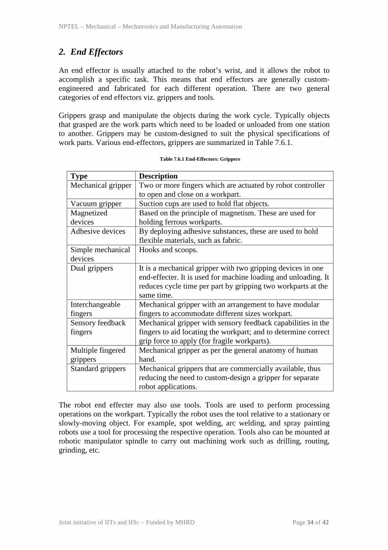
Grippers grasp and manipulate the objects during the work cycle. Typically objects that grasped are the work parts which need to be loaded or unloaded from one station to another. Grippers may be custom-designed to suit the physical specifications of work parts. Various end-effectors, grippers are summarized in Table 7.6.1.
Table 7.6.1 End-Effectors: Grippers
Type Description Mechanical gripper Two or more fingers which are actuated by robot controller
to open and close on a workpart. Vacuum gripper Suction cups are used to hold flat objects. Magnetized devices
Based on the principle of magnetism. These are used for holding ferrous workparts.
Adhesive devices By deploying adhesive substances, these are used to hold flexible materials, such as fabric.
Simple mechanical devices
Hooks and scoops.
Dual grippers It is a mechanical gripper with two gripping devices in one end-effecter. It is used for machine loading and unloading. It reduces cycle time per part by gripping two workparts at the same time.
Interchangeable fingers
Mechanical gripper with an arrangement to have modular fingers to accommodate different sizes workpart.
Sensory feedback fingers
Mechanical gripper with sensory feedback capabilities in the fingers to aid locating the workpart; and to determine correct grip force to apply (for fragile workparts).
Multiple fingered grippers
Mechanical gripper as per the general anatomy of human hand.
Standard grippers Mechanical grippers that are commercially available, thus reducing the need to custom-design a gripper for separate robot applications.
The robot end effecter may also use tools. Tools are used to perform processing operations on the workpart. Typically the robot uses the tool relative to a stationary or slowly-moving object. For example, spot welding, arc welding, and spray painting robots use a tool for processing the respective operation. Tools also can be mounted at robotic manipulator spindle to carry out machining work such as drilling, routing, grinding, etc.
NPTEL – Mechanical – Mechatronics and Manufacturing Automation
Joint initiative of IITs and IISc – Funded by MHRD Page 35 of 42
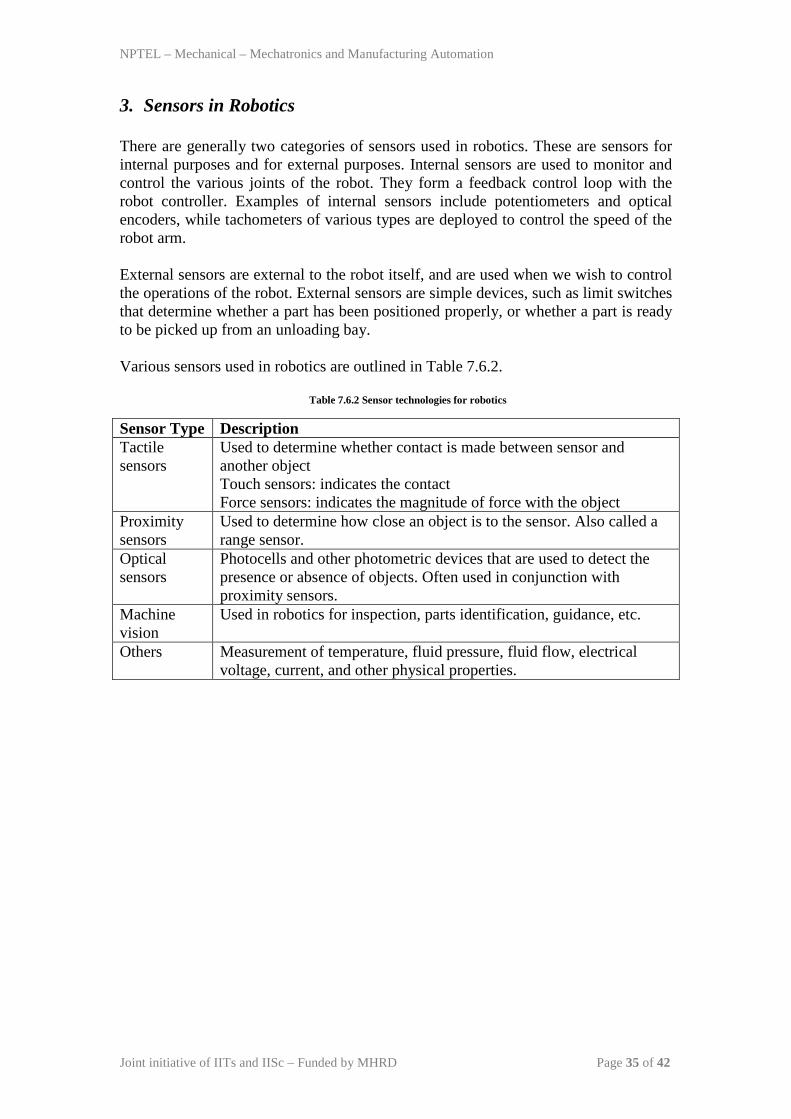
3. Sensors in Robotics There are generally two categories of sensors used in robotics. These are sensors for internal purposes and for external purposes. Internal sensors are used to monitor and control the various joints of the robot. They form a feedback control loop with the robot controller. Examples of internal sensors include potentiometers and optical encoders, while tachometers of various types are deployed to control the speed of the robot arm. External sensors are external to the robot itself, and are used when we wish to control the operations of the robot. External sensors are simple devices, such as limit switches that determine whether a part has been positioned properly, or whether a part is ready to be picked up from an unloading bay. Various sensors used in robotics are outlined in Table 7.6.2.
Table 7.6.2 Sensor technologies for robotics
Sensor Type Description Tactile sensors
Used to determine whether contact is made between sensor and another object Touch sensors: indicates the contact Force sensors: indicates the magnitude of force with the object
Proximity sensors
Used to determine how close an object is to the sensor. Also called a range sensor.
Optical sensors
Photocells and other photometric devices that are used to detect the presence or absence of objects. Often used in conjunction with proximity sensors.
Machine vision
Used in robotics for inspection, parts identification, guidance, etc.
Others Measurement of temperature, fluid pressure, fluid flow, electrical voltage, current, and other physical properties.
NPTEL – Mechanical – Mechatronics and Manufacturing Automation
Joint initiative of IITs and IISc – Funded by MHRD Page 36 of 42
4. Industrial Robot Applications:
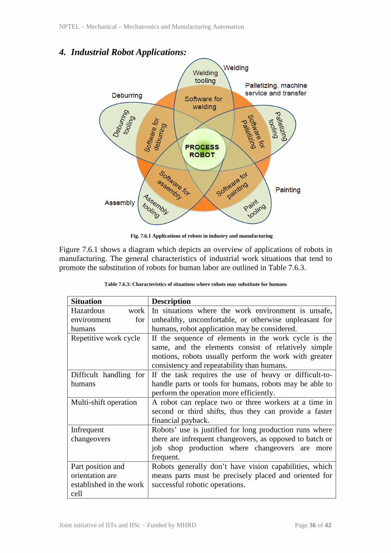
Fig. 7.6.1 Applications of robots in industry and manufacturing
Figure 7.6.1 shows a diagram which depicts an overview of applications of robots in manufacturing. The general characteristics of industrial work situations that tend to promote the substitution of robots for human labor are outlined in Table 7.6.3.
Table 7.6.3: Characteristics of situations where robots may substitute for humans Situation Description Hazardous work environment for humans
In situations where the work environment is unsafe, unhealthy, uncomfortable, or otherwise unpleasant for humans, robot application may be considered.
Repetitive work cycle If the sequence of elements in the work cycle is the same, and the elements consist of relatively simple motions, robots usually perform the work with greater consistency and repeatability than humans.
Difficult handling for humans
If the task requires the use of heavy or difficult-to-handle parts or tools for humans, robots may be able to perform the operation more efficiently.
Multi-shift operation A robot can replace two or three workers at a time in second or third shifts, thus they can provide a faster financial payback.
Infrequent changeovers
Robots’ use is justified for long production runs where there are infrequent changeovers, as opposed to batch or job shop production where changeovers are more frequent.
Part position and orientation are established in the work cell
Robots generally don’t have vision capabilities, which means parts must be precisely placed and oriented for successful robotic operations.
NPTEL – Mechanical – Mechatronics and Manufacturing Automation
Joint initiative of IITs and IISc – Funded by MHRD Page 37 of 42
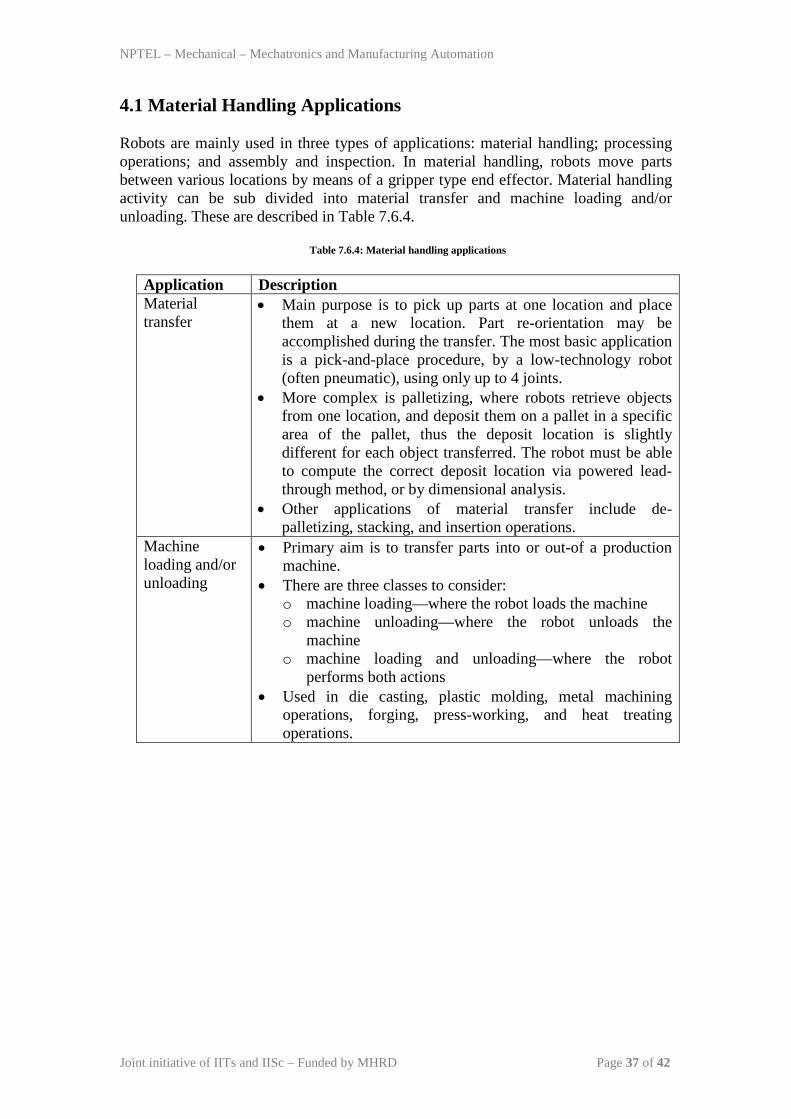
4.1 Material Handling Applications
Robots are mainly used in three types of applications: material handling; processing operations; and assembly and inspection. In material handling, robots move parts between various locations by means of a gripper type end effector. Material handling activity can be sub divided into material transfer and machine loading and/or unloading. These are described in Table 7.6.4.
Table 7.6.4: Material handling applications
Application Description Material transfer
• Main purpose is to pick up parts at one location and place them at a new location. Part re-orientation may be accomplished during the transfer. The most basic application is a pick-and-place procedure, by a low-technology robot (often pneumatic), using only up to 4 joints.
• More complex is palletizing, where robots retrieve objects from one location, and deposit them on a pallet in a specific area of the pallet, thus the deposit location is slightly different for each object transferred. The robot must be able to compute the correct deposit location via powered lead-through method, or by dimensional analysis.
• Other applications of material transfer include de-palletizing, stacking, and insertion operations.
Machine loading and/or unloading
• Primary aim is to transfer parts into or out-of a production machine.
• There are three classes to consider: o machine loading—where the robot loads the machine o machine unloading—where the robot unloads the
machine o machine loading and unloading—where the robot
performs both actions • Used in die casting, plastic molding, metal machining
operations, forging, press-working, and heat treating operations.
NPTEL – Mechanical – Mechatronics and Manufacturing Automation
Joint initiative of IITs and IISc – Funded by MHRD Page 38 of 42
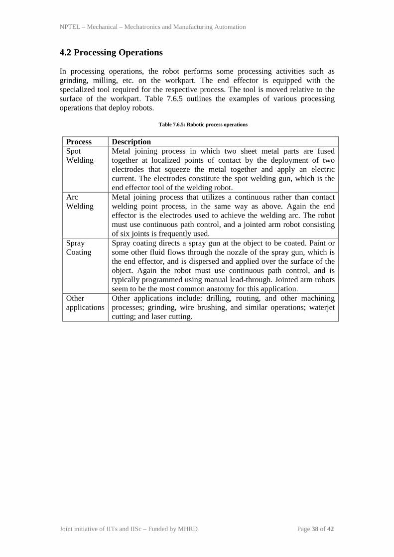
4.2 Processing Operations
In processing operations, the robot performs some processing activities such as grinding, milling, etc. on the workpart. The end effector is equipped with the specialized tool required for the respective process. The tool is moved relative to the surface of the workpart. Table 7.6.5 outlines the examples of various processing operations that deploy robots.
Table 7.6.5: Robotic process operations
Process Description Spot Welding
Metal joining process in which two sheet metal parts are fused together at localized points of contact by the deployment of two electrodes that squeeze the metal together and apply an electric current. The electrodes constitute the spot welding gun, which is the end effector tool of the welding robot.
Arc Welding
Metal joining process that utilizes a continuous rather than contact welding point process, in the same way as above. Again the end effector is the electrodes used to achieve the welding arc. The robot must use continuous path control, and a jointed arm robot consisting of six joints is frequently used.
Spray Coating
Spray coating directs a spray gun at the object to be coated. Paint or some other fluid flows through the nozzle of the spray gun, which is the end effector, and is dispersed and applied over the surface of the object. Again the robot must use continuous path control, and is typically programmed using manual lead-through. Jointed arm robots seem to be the most common anatomy for this application.
Other applications
Other applications include: drilling, routing, and other machining processes; grinding, wire brushing, and similar operations; waterjet cutting; and laser cutting.
NPTEL – Mechanical – Mechatronics and Manufacturing Automation
Joint initiative of IITs and IISc – Funded by MHRD Page 39 of 42
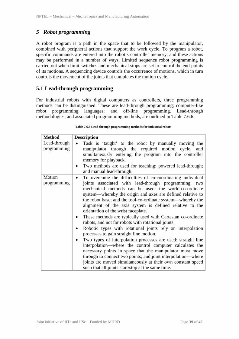
5 Robot programming
A robot program is a path in the space that to be followed by the manipulator, combined with peripheral actions that support the work cycle. To program a robot, specific commands are entered into the robot’s controller memory, and these actions may be performed in a number of ways. Limited sequence robot programming is carried out when limit switches and mechanical stops are set to control the end-points of its motions. A sequencing device controls the occurrence of motions, which in turn controls the movement of the joints that completes the motion cycle.
5.1 Lead-through programming
For industrial robots with digital computers as controllers, three programming methods can be distinguished. These are lead-through programming; computer-like robot programming languages; and off-line programming. Lead-through methodologies, and associated programming methods, are outlined in Table 7.6.6.
Table 7.6.6 Lead-through programming methods for industrial robots
Method Description Lead-through programming
• Task is ‘taught’ to the robot by manually moving the manipulator through the required motion cycle, and simultaneously entering the program into the controller memory for playback.
• Two methods are used for teaching: powered lead-through; and manual lead-through.
Motion programming
• To overcome the difficulties of co-coordinating individual joints associated with lead-through programming, two mechanical methods can be used: the world-co-ordinate system—whereby the origin and axes are defined relative to the robot base; and the tool-co-ordinate system—whereby the alignment of the axis system is defined relative to the orientation of the wrist faceplate.
• These methods are typically used with Cartesian co-ordinate robots, and not for robots with rotational joints.
• Robotic types with rotational joints rely on interpolation processes to gain straight line motion.
• Two types of interpolation processes are used: straight line interpolation—where the control computer calculates the necessary points in space that the manipulator must move through to connect two points; and joint interpolation—where joints are moved simultaneously at their own constant speed such that all joints start/stop at the same time.
NPTEL – Mechanical – Mechatronics and Manufacturing Automation
Joint initiative of IITs and IISc – Funded by MHRD Page 40 of 42
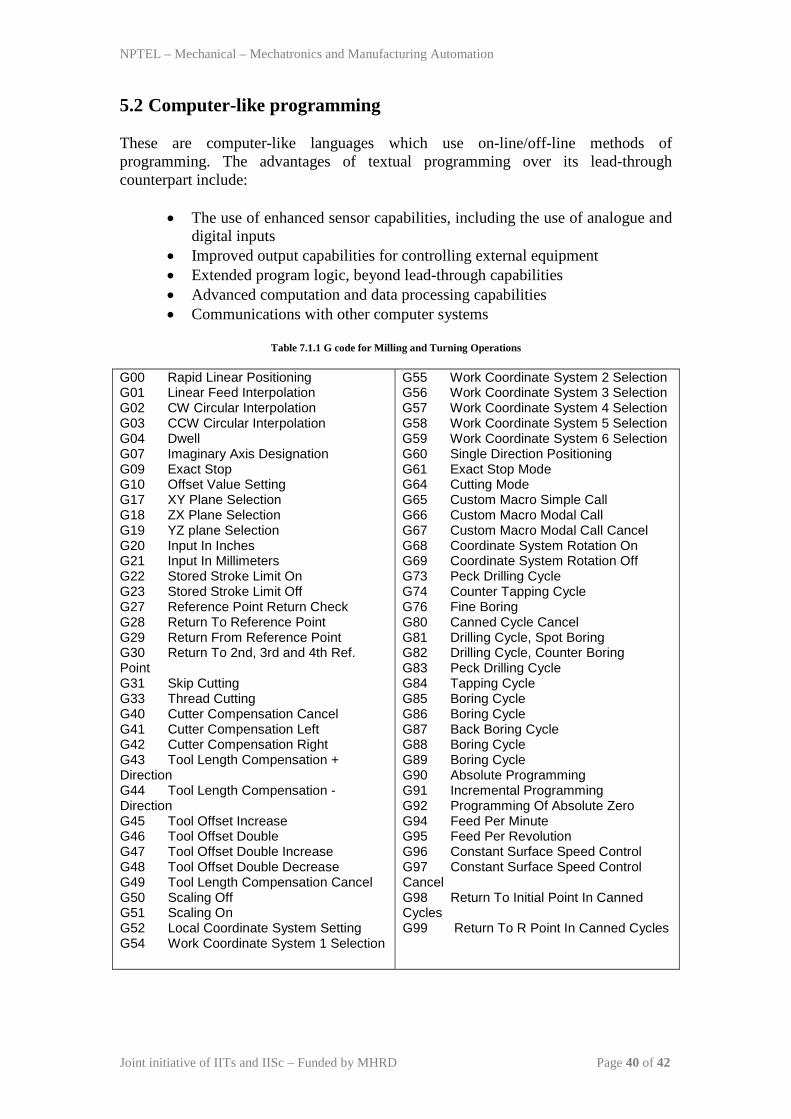
5.2 Computer-like programming
These are computer-like languages which use on-line/off-line methods of programming. The advantages of textual programming over its lead-through counterpart include:
• The use of enhanced sensor capabilities, including the use of analogue and
digital inputs • Improved output capabilities for controlling external equipment • Extended program logic, beyond lead-through capabilities • Advanced computation and data processing capabilities • Communications with other computer systems
Table 7.1.1 G code for Milling and Turning Operations
G00 Rapid Linear Positioning G01 Linear Feed Interpolation G02 CW Circular Interpolation G03 CCW Circular Interpolation G04 Dwell G07 Imaginary Axis Designation G09 Exact Stop G10 Offset Value Setting G17 XY Plane Selection G18 ZX Plane Selection G19 YZ plane Selection G20 Input In Inches G21 Input In Millimeters G22 Stored Stroke Limit On G23 Stored Stroke Limit Off G27 Reference Point Return Check G28 Return To Reference Point G29 Return From Reference Point G30 Return To 2nd, 3rd and 4th Ref. Point G31 Skip Cutting G33 Thread Cutting G40 Cutter Compensation Cancel G41 Cutter Compensation Left G42 Cutter Compensation Right G43 Tool Length Compensation + Direction G44 Tool Length Compensation - Direction G45 Tool Offset Increase G46 Tool Offset Double G47 Tool Offset Double Increase G48 Tool Offset Double Decrease G49 Tool Length Compensation Cancel G50 Scaling Off G51 Scaling On G52 Local Coordinate System Setting G54 Work Coordinate System 1 Selection
G55 Work Coordinate System 2 Selection G56 Work Coordinate System 3 Selection G57 Work Coordinate System 4 Selection G58 Work Coordinate System 5 Selection G59 Work Coordinate System 6 Selection G60 Single Direction Positioning G61 Exact Stop Mode G64 Cutting Mode G65 Custom Macro Simple Call G66 Custom Macro Modal Call G67 Custom Macro Modal Call Cancel G68 Coordinate System Rotation On G69 Coordinate System Rotation Off G73 Peck Drilling Cycle G74 Counter Tapping Cycle G76 Fine Boring G80 Canned Cycle Cancel G81 Drilling Cycle, Spot Boring G82 Drilling Cycle, Counter Boring G83 Peck Drilling Cycle G84 Tapping Cycle G85 Boring Cycle G86 Boring Cycle G87 Back Boring Cycle G88 Boring Cycle G89 Boring Cycle G90 Absolute Programming G91 Incremental Programming G92 Programming Of Absolute Zero G94 Feed Per Minute G95 Feed Per Revolution G96 Constant Surface Speed Control G97 Constant Surface Speed Control Cancel G98 Return To Initial Point In Canned Cycles G99 Return To R Point In Canned Cycles
NPTEL – Mechanical – Mechatronics and Manufacturing Automation
Joint initiative of IITs and IISc – Funded by MHRD Page 41 of 42
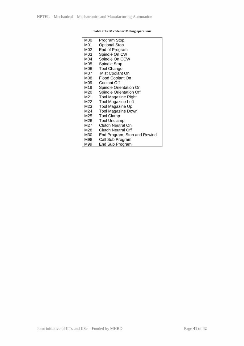
Table 7.1.2 M code for Milling operations
M00 Program Stop M01 Optional Stop M02 End of Program M03 Spindle On CW M04 Spindle On CCW M05 Spindle Stop M06 Tool Change M07 Mist Coolant On M08 Flood Coolant On M09 Coolant Off M19 Spindle Orientation On M20 Spindle Orientation Off M21 Tool Magazine Right M22 Tool Magazine Left M23 Tool Magazine Up M24 Tool Magazine Down M25 Tool Clamp M26 Tool Unclamp M27 Clutch Neutral On M28 Clutch Neutral Off M30 End Program, Stop and Rewind M98 Call Sub Program M99 End Sub Program
NPTEL – Mechanical – Mechatronics and Manufacturing Automation
Joint initiative of IITs and IISc – Funded by MHRD Page 42 of 42
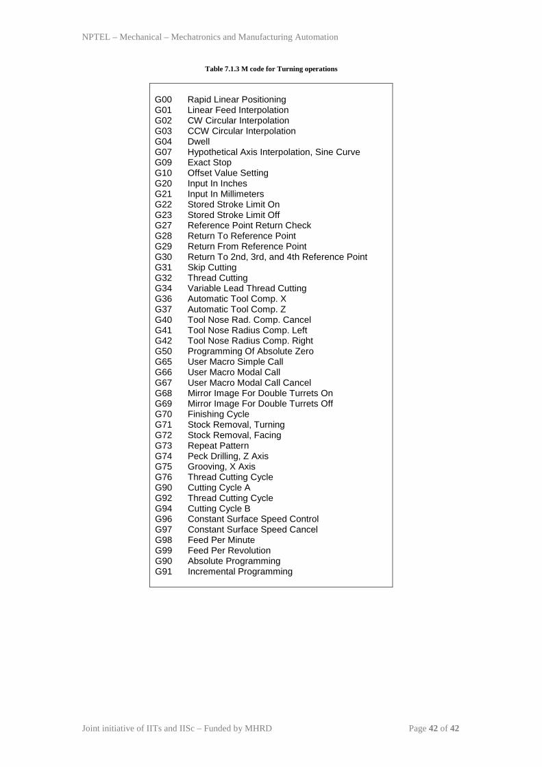
Table 7.1.3 M code for Turning operations
G00 Rapid Linear Positioning G01 Linear Feed Interpolation G02 CW Circular Interpolation G03 CCW Circular Interpolation G04 Dwell G07 Hypothetical Axis Interpolation, Sine Curve G09 Exact Stop G10 Offset Value Setting G20 Input In Inches G21 Input In Millimeters G22 Stored Stroke Limit On G23 Stored Stroke Limit Off G27 Reference Point Return Check G28 Return To Reference Point G29 Return From Reference Point G30 Return To 2nd, 3rd, and 4th Reference Point G31 Skip Cutting G32 Thread Cutting G34 Variable Lead Thread Cutting G36 Automatic Tool Comp. X G37 Automatic Tool Comp. Z G40 Tool Nose Rad. Comp. Cancel G41 Tool Nose Radius Comp. Left G42 Tool Nose Radius Comp. Right G50 Programming Of Absolute Zero G65 User Macro Simple Call G66 User Macro Modal Call G67 User Macro Modal Call Cancel G68 Mirror Image For Double Turrets On G69 Mirror Image For Double Turrets Off G70 Finishing Cycle G71 Stock Removal, Turning G72 Stock Removal, Facing G73 Repeat Pattern G74 Peck Drilling, Z Axis G75 Grooving, X Axis G76 Thread Cutting Cycle G90 Cutting Cycle A G92 Thread Cutting Cycle G94 Cutting Cycle B G96 Constant Surface Speed Control G97 Constant Surface Speed Cancel G98 Feed Per Minute G99 Feed Per Revolution G90 Absolute Programming G91 Incremental Programming