Embed Size (px)
Citation preview
MT-CNCFollower and Gantry Axes
DOK-MT*CNC-FOL*GAN*V15-ANW1-EN-P
Applikation Manual
mannesmannRexroth
engineering
Indramat271997
Follower and Gantry Axes
About this document DOK-MT*CNC-FOL*GAN*V15-ANW1-EN-E1,44 � 06.97
Follower and Gantry Axes
Application Manual
DOK-MT*CNC-FOL*GAN*V15-ANW1-EN-E1,44
� Mappe 5 Reg 5
� M505197E.pdf
� Drawing no.: 109-0668-4197-00
Functional description of the CNC-function Follower and Gantry Axes.
This electronic document is based on the hardcopy document withdocument desig.: DOK-MT*CNC-FOL*GAN*V15-ANW1-EN-P
Revision Date Remarks
4197-00 07/95 New issue
DOK-MT*CNC-FOL*GAN*V15-ANW1-EN-E1,44 06/97 1st E-Dok
� INDRAMAT GmbH, 1996
Copying this document, and giving it to others and the use orcommunication of the contents thereof without express authority, areforbidden. Offenders are liable for the payment of damages. All rights arereserved in the event of the grant of a patent or the registration of a utilitymodel or design (DIN 34-1).
The electronic documentation (E-doc) may be copied as often as neededif such are to be used by the customer for the purpose intended.
INDRAMAT GmbH � Bgm.-Dr.-Nebel-Str. 2 � D-97816 Lohr a. Main
Phone 09352/40-0 � Tx 689421 � Fax 09352/40-4885
ENC (GL)
Titel
Kind of documentation
Docu-Type
Internal filing remarks
Purpose of this document
Reference
Copyright
Published by
Follower and Gantry Axes
DOK-MT*CNC-FOL*GAN*V15-ANW1-EN-E1,44 � 06.97 Table of Contents I
Table of Contents
1 Introduction................................................................................................................. .1-1
2 Scope of the Function .................................................................................................2-12.1 Linking of Lead and Follower Axes ......................................................................................................2-1
2.2 Legal Configurations ............................................................................................................................2-1
2.3 Legal Axis Types ..................................................................................................................................2-2
2.4 NC-programming..................................................................................................................................2-2
2.5 Activate and Deactivate Synchronized Axis Group ..............................................................................2-3
2.6 Tests Performed at the Start of and During Synchronous Operation...................................................2-3
3 Exception Conditions..................................................................................................3-13.1 End of Program and Control Reset ......................................................................................................3-1
3.2 Axis Transfer ........................................................................................................................................3-1
3.3 Axis Referencing (Homing) ..................................................................................................................3-1
3.4 Feed to Positive Stop ...........................................................................................................................3-3
3.5 Coordinate Transformation Function....................................................................................................3-3
3.6 Process Operating Mode Selection......................................................................................................3-3
3.7 ‘C-Axis’ - Main Spindle and Main Spindle with Associated Rotary Axis ...............................................3-3
3.8 Manual Traversing of Follower Axes....................................................................................................3-4
3.9 Process Enable ....................................................................................................................................3-4
3.10 Emergency Stop.................................................................................................................................3-4
3.11 Axis-Specific Status Signals...............................................................................................................3-4
3.12 Axis-Specific Control Signals .............................................................................................................3-4
4 Machine Data................................................................................................................4 -14.1 Structure of Relevant Machine Data ....................................................................................................4-1
4.2 Modify Machine Data............................................................................................................................4-1
4.3 Description of the Individual Data Elements.........................................................................................4-2
Synchronized Axis Group Is Active ...............................................................................................4-2
Lead Axis in Coordinate System ...................................................................................................4-2
Follower Axis in Coordinate System..............................................................................................4-2
Translation Ratio for Follower Axis................................................................................................4-3
Direction of Follower Axis ..............................................................................................................4-3
Follower Axis = Gantry Axis..........................................................................................................4-3
5 Gateway Control Signals ............................................................................................5-15.1 Activate Synchronized Axis Group .......................................................................................................5-1
5.2 Synchronized Axis Group Is Active ......................................................................................................5-1
Follower and Gantry Axes
II Table of Contents DOK-MT*CNC-FOL*GAN*V15-ANW1-EN-E1,44 � 06.97
6 Example: Slaving a Follower Rest ...........................................................................6-16.1 NC-program .........................................................................................................................................6-1
6.2 SPS Program .......................................................................................................................................6-2
6.3 Machine Data .......................................................................................................................................6-3
7 Startup Information .....................................................................................................7-1
8 Index ........................................................................................................................ .....8-1
9 List of Illustrations.......................................................................................................8 -1
Follower and Gantry Axes
DOK-MT*CNC-FOL*GAN*V15-ANW1-EN-E1,44 � 06.97 Introduction 1-1
1 IntroductionThe function ‘follower (synchronized) axis control’ or ‘gantry axes’ referredto below as ‘synchronized mode’ allows up to four feed axes to beoperated in synch.
Each feed axis can be declared a ‘lead axis.’ Up to three ‘follower axes’(slave axes) can be assigned to run in synch with the lead axis. The leadaxis and the follower axes work together to form a synchronized axisgroup. Synchronized axis groups can be activated or deactivated regard-less of the operating mode active at any one time, or they can be main-tained during the entire operation of the machine, including referencing.When they are in the inactive state, they can be reconfigured during ma-chine operation from the SPS and the CNC as well as via the user inter-face (MUI/GUI). Up to 4 different synchronized axis groups can be activeat the same time per process.
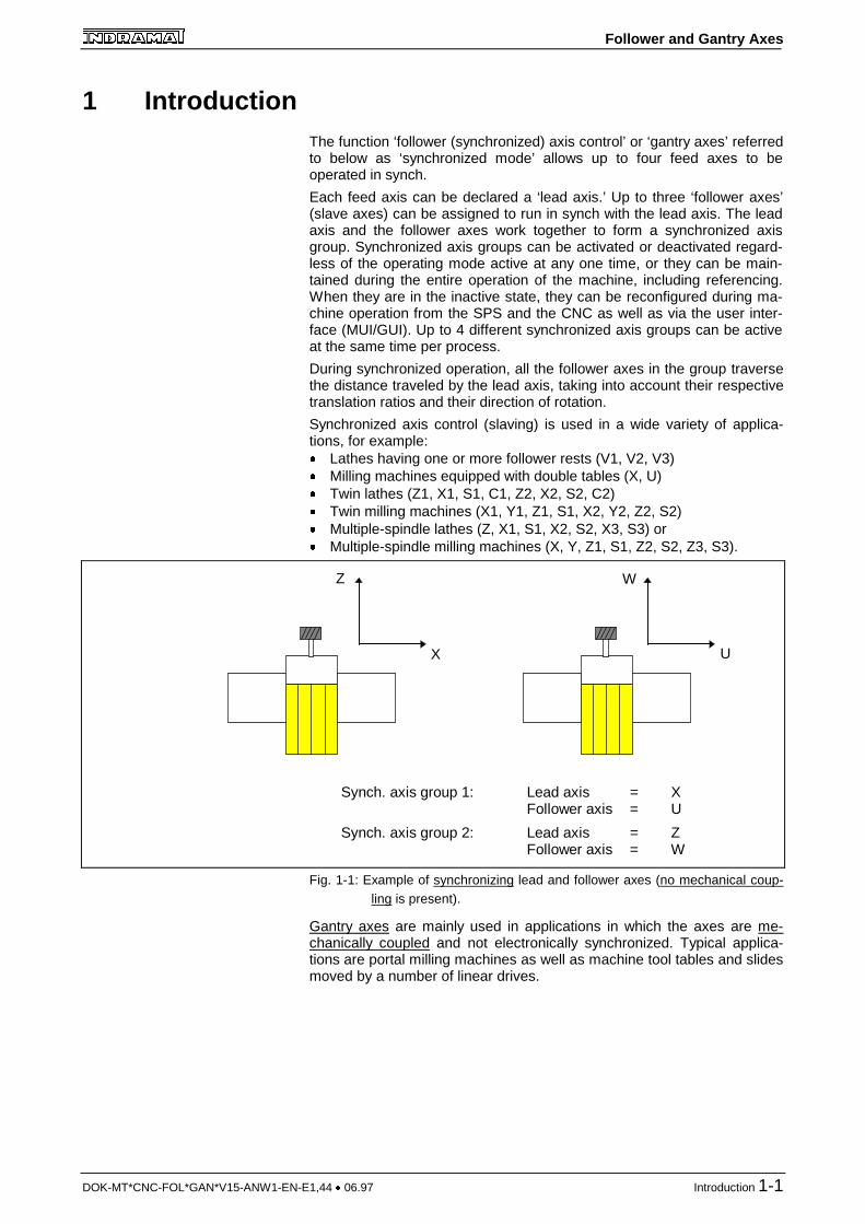
During synchronized operation, all the follower axes in the group traversethe distance traveled by the lead axis, taking into account their respectivetranslation ratios and their direction of rotation.
Synchronized axis control (slaving) is used in a wide variety of applica-tions, for example:� Lathes having one or more follower rests (V1, V2, V3)� Milling machines equipped with double tables (X, U)� Twin lathes (Z1, X1, S1, C1, Z2, X2, S2, C2)� Twin milling machines (X1, Y1, Z1, S1, X2, Y2, Z2, S2)� Multiple-spindle lathes (Z, X1, S1, X2, S2, X3, S3) or� Multiple-spindle milling machines (X, Y, Z1, S1, Z2, S2, Z3, S3).
Synch. axis group 1: Lead axis = XFollower axis = U
Synch. axis group 2: Lead axis = ZFollower axis = W
X
W
U
Z
Fig. 1-1: Example of synchronizing lead and follower axes (no mechanical coup-ling is present).
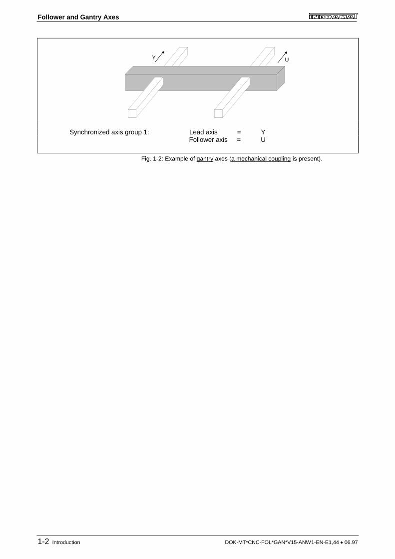
Gantry axes are mainly used in applications in which the axes are me-chanically coupled and not electronically synchronized. Typical applica-tions are portal milling machines as well as machine tool tables and slidesmoved by a number of linear drives.
Follower and Gantry Axes
1-2 Introduction DOK-MT*CNC-FOL*GAN*V15-ANW1-EN-E1,44 � 06.97
Y U
Synchronized axis group 1: Lead axis = YFollower axis = U
Fig. 1-2: Example of gantry axes (a mechanical coupling is present).
Follower and Gantry Axes
DOK-MT*CNC-FOL*GAN*V15-ANW1-EN-E1,44 � 06.97 Scope of the Function 2-1
2 Scope of the Function
2.1 Linking of Lead and Follower Axes
The change in the position command values for the lead axis taking intoaccount the respective translation ratios between the lead and followeraxis is sent to the follower axes at the interpolation clock.
Offset registers for offsetting the follower axes relative to the lead axis arenot provided since the lead and follower axes must always be traversed totheir initial position before the synchronized mode is activated and sincethe CNC maintains the initial offset between the lead axis and the followeraxis during the course of synchronized operation.
In addition to the translation ratio, the direction of rotation of the followeraxes can be specified in the machine data.
2.2 Legal Configurations
The following rules describe the configurations which are legal for thesynchronized mode. If the CNC detects a violation of these rules, it inter-rupts processing and generates an error message.
� One lead axis and at least one follower axis must be belong to eachsynchronized axis group.
� A synchronized axis group must not contain more than one lead axis.
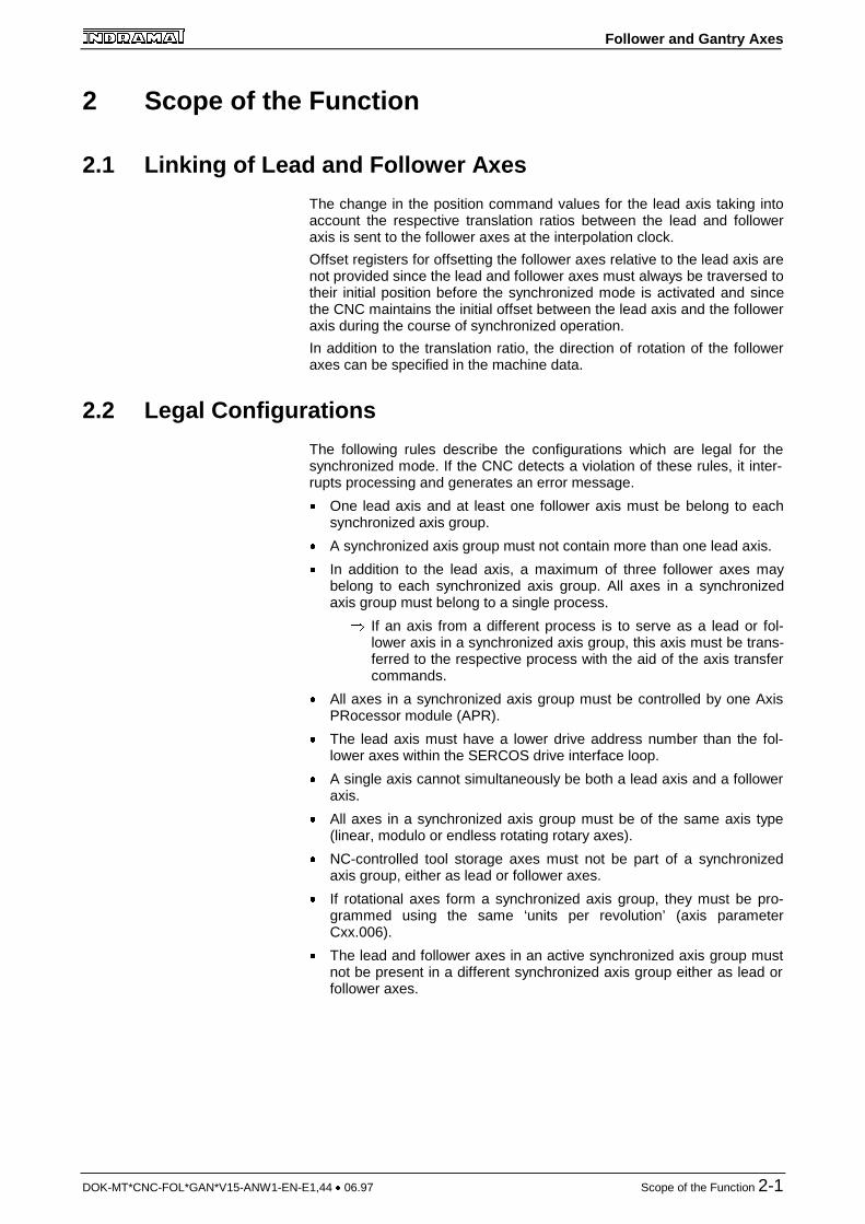
� In addition to the lead axis, a maximum of three follower axes maybelong to each synchronized axis group. All axes in a synchronizedaxis group must belong to a single process.
� If an axis from a different process is to serve as a lead or fol-lower axis in a synchronized axis group, this axis must be trans-ferred to the respective process with the aid of the axis transfercommands.
� All axes in a synchronized axis group must be controlled by one AxisPRocessor module (APR).
� The lead axis must have a lower drive address number than the fol-lower axes within the SERCOS drive interface loop.
� A single axis cannot simultaneously be both a lead axis and a followeraxis.
� All axes in a synchronized axis group must be of the same axis type(linear, modulo or endless rotating rotary axes).
� NC-controlled tool storage axes must not be part of a synchronizedaxis group, either as lead or follower axes.
� If rotational axes form a synchronized axis group, they must be pro-grammed using the same ‘units per revolution’ (axis parameterCxx.006).
� The lead and follower axes in an active synchronized axis group mustnot be present in a different synchronized axis group either as lead orfollower axes.
Follower and Gantry Axes
2-2 Scope of the Function DOK-MT*CNC-FOL*GAN*V15-ANW1-EN-E1,44 � 06.97
1) One Lead Axis and One Follower Axis
2) One Lead Axis and Two Follower Axes
3) One Lead Axis and Three Follower Axes
Lead Axis
Follower Axis 1
LA
FA1
Follower Axis 2 FA2
Follower Axis 1
Lead Axis LA
FA1
Follower Axis 3 FA3
Follower Axis 2 FA2
Lead Axis LA Follower Axis 1 FA1
Fig. 2-1: Legal synchronized axis groups within a process for axis synchroniza-tion and for gantry mode.
2.3 Legal Axis Types
All axis types with the exception of tool storage axes, spindles, and com-bined spindle/turret axes may also be used in a synchronized axis group.Specifically, the legal axis types may be:
� digital linear axes
� digital modulo rotary axes
� digital limited rotary axes
� digital spindles capable of being rotational axes in the rotational axismode or
� digital spindles to which a digital axis is assigned in the rotational axismode
However, either only
� linear axes or
� endless (modulo) rotary axes or
� finite rotary axes
may belong to a synchronized axis group.
It is not possible to mix these primary groups. Digital modulo rotary axes,spindles capable of serving as rotational axes as well as spindles to whicha rotational axis is assigned may belong to a synchronized axis groupconsisting of modulo rotary axes.
2.4 NC-programming
During synchronized operation, the user must not program any axis otherthan the lead axis of an active synchronized axis group. All other followeraxes must not be programmed during synchronized operation. If the userattempts to do this, for example by mirror imaging or scaling a followeraxes, the CNC interrupts program execution and generates a processerror with message.
Follower and Gantry Axes
DOK-MT*CNC-FOL*GAN*V15-ANW1-EN-E1,44 � 06.97 Scope of the Function 2-3
Zero offsets (including plane rotations) and tool corrections (including Dcorrections) are taken into account by the CNC solely for the lead axis.During synchronized operation, the follower axes are supplied with thecommand values for the lead axis, taking into account the respectivetranslation ratio and direction of rotation.
2.5 Activate and Deactivate Synchronized Axis Group
A synchronized axis group can be activated and deactivated from theCNC-program using an auxiliary function. In manual mode, the user canactivate and deactivate synchronized operation by means of a machinekey or some other key.
A gateway signal between the SPS and the CNC allows synchronizedoperation to be activated and deactivated. It is important that the lead andfollower axes be traversed to their initial position before activatingsynchronized operation and that the appropriate Machine Data be para-meterized properly.
Once synchronized operation has been deactivated, all the axes in thesynchronized axis group keep the same position.
2.6 Tests Performed at the Start of and During SynchronousOperation
When a synchronized axis group is activated, the CNC calculates themaximum velocity, the maximum intermittent speed, and the maximumacceleration of the lead axis for synchronized operation taking into ac-count the appropriate parameters and the existing translation ratios of allaxes belonging to the synchronized axis group.
In addition, during synchronized operation, as in all other forms of inter-polation, the CNC checks to see if any of the axes in the group haveexceeded their traverse range limits. This is done before the CNC pro-cesses an NC-block. If the CNC detects that one of the follower axes hasexceeded the traverse range limits, it interrupts processing (as with all theother axes) and generates an error message.

Follower and Gantry Axes
DOK-MT*CNC-FOL*GAN*V15-ANW1-EN-E1,44 � 06.97 Exception Conditions 3-1
3 Exception Conditions
3.1 End of Program and Control Reset
Synchronized operation remains active at end-of-program (BST, RET,JMP, M02 and M30), at Control Reset and during jog in the manual modeprovided that the SPS does not use control signals to deactivate thesynchronized axis groups.
3.2 Axis Transfer
During synchronized operation, the user may not transfer the axis invol-ved in the synchronized axis group between processes. The use of theaxis transfer commands on axes which are taking part in synchronizedoperation causes execution of the program to terminate and an errormessage to be issued.
Axes which are involved in synchronized operation and also belong to adifferent primary process therefore must be transferred to the respectiveprocess before the respective axis group is activated. These axes maynot be returned to the primary process until the synchronized axis grouphas been deactivated.
WARNING
� If axes which belong to a different primary process areinvolved in a synchronized axis group, the syn-chronization mode must be deactivated prior to theaxis enable and thus prior to the end of the CNC-pro-gram (BST, RET, JMP, M02, M30), control reset orinitial jogging (only if process parameter Bxx.036‘Manual Axis Jogging Causes Reset’ is set to ‘yes.’)At end-of-program (M02 and M30), Control Reset,and upon initial jogging (only if the process parameterBxx.036 ‘Manual Axis Jogging Causes Reset’ is set to‘yes’), the SPS can deactivate the respective syn-chronized axis group before the CNC enables the re-spective axes.
3.3 Axis Referencing (Homing)
Axes which are not linked mechanically can be referenced individuallywhen the synchronized axis group is inactive.
However, mechanically linked axes (gantry axes) can only be referencedunder certain very specific circumstances during synchronized operation.
The essential requirements for this to be done include correct encoderselection, proper parameterization of digital drives equipped with aSERCOS interface (see application description ‘Intelligent DigitalAC-Servo Drives Equipped with a SERCOS Interface‘, section on ‘Drive-Controlled Referencing’, and the section on ‘Gantry Axes’).
With very rigid links between gantry axes, such as those encountered onmachine tool tables which are moved by a number of linear drives, a di-rect encoder which measures in relative terms (incremental linear scale)is sufficient.
With structures which can be compromised by torsion, for example onportal milling machines, an absolute measuring system is necessary foreach axis. INDRAMAT recommends that an integrated multiturn encoderbe used for each drive as well as an incremental scale for direct measu-rement.
Follower and Gantry Axes
3-2 Exception Conditions DOK-MT*CNC-FOL*GAN*V15-ANW1-EN-E1,44 � 06.97
A synchronized axis group which is used to operate mechanically linkedaxes in synch must be activated by setting the appropriate gateway signalafter the drives have been supplied with power.
WARNING
� Before the synchronized axis group is activated, theSPS has to deactivate the integral action time com-ponent of the follower axes via the SERCOS servicedata channel (regardless of the type of feedbackused). If this action is taken, the axes can also bejogged in manual mode when the axes are undermechanical load, which can sometimes occur fol-lowing power-on, until they are aligned and, if needbe, referenced in program-controlled mode.
� For reasons of safety, it may be necessary to alignmechanically linked axes with one another and tomonitor their torque loads.
1) Absolute Feedback Measuring System
If axes in an active synchronized axis group are equipped with abso-lute measuring systems, they do not need to be referenced, since assoon as power is supplied, the absolute measuring systems imme-diately send valid actual positions to the drive amplifier and the con-troller.
Because of possible stresses in the mechanical structure, it is sug-gested that gantry axes be aligned with one another under programcontrol. The adjustment moves are best performed with the aid of the‘HOME’ program.
Perform the following steps in the ‘HOME’ program:
� Deactivate the synchronized axis group.
� Activate the integral component of the follower axes.
� Move the follower axes to the position of the lead axis.
� Reactivate the synchronized axis group.
2) Incremental Feedback Measuring System
The referencing operation itself is initiated by means of the referencingcommand ‘G74’ for the lead axis, for by activating the Gatewayinterface signal ‘AxxC.HOME’ of the lead axis. The CNC then tra-verses the axes in the synchronized axis group in a synchronousmanner until the reference switch is activated, all axes have reachedtheir encoder zero mark, and their ‘reference dimension offset 2’ hasbeen completely traversed.
The requirements necessary for this must be met as stated in the ap-plications description ‘Intelligent Digital AC Servo Drives Equipped withSERCOS Interface’ in the sections on ‘Drive-Controlled Referencing”and ‘Gantry Axes.”
Any adjustment moves which may be required must be performedprior to referencing. For this reason, only program-controlled refe-rencing should be allowed.
Perform the following steps in the ‘HOME’ program:
� Deactivate the synchronized axis group.
� Activate the integral component of the follower axes.
� Move the follower axes to the position of the lead axis.
� Reactivate the synchronized axis group.
� Reference axes (‘G74’ for lead axis).
Steps of the ReferencingOperation
Follower and Gantry Axes
DOK-MT*CNC-FOL*GAN*V15-ANW1-EN-E1,44 � 06.97 Exception Conditions 3-3
3) Multiturn Encoder on Motor and Additional Incremental MeasuringSystem
After being powered ON, the multiturn encoders immediately sendvalid actual values to the drive amplifiers and to the controller. The si-gnaled actual positions do, however, deviate from the actual currentposition by the inaccuracy which results from the indirect form ofmeasurement, which is why the gantry axes must be referenced inspite of the presence of an absolute encoder.
Since the actual values following power ON are not accurate enoughwith gantry applications and since the effect of strain within the me-chanical structure must be minimized, it is a good idea before tra-versing to the reference point to traverse the follower axis to the posi-tion of the lead axis with the synchronized axis group deactivated.
Any adjustment moves which may prove necessary must be pro-grammed in the ‘HOME’ program in addition to the referencing moves.In this program, use the same sequence of steps as with theincremental measuring system (see above).
WARNING
� In some circumstances given the existing mechanicalconditions —for example, linearity errors on scales —it may be necessary to set the integral component ofthe follower axes to a value lower than that of the leadaxis.
3.4 Feed to Positive Stop
Feed to positive stop cannot be used with synchronized mode. If the userprograms traversing to a positive stop for a lead or follower axis belongingto an active synchronized axis group, the CNC responds by terminatingprogram execution and issuing a process error with message.
3.5 Coordinate Transformation Function
When coordinate transformation is active (G31), the axes which areinvolved in the transformation (axes whose meanings are X and C) mustnot participate in any active synchronized axis group.
3.6 Process Operating Mode Selection
Changing the operating mode does not have any effect on synchronizedoperation. The link between the axes remains intact.
3.7 ‘C-Axis’ - Main Spindle and Main Spindle with AssociatedRotary Axis
If ‘C-axis’ capable spindles or spindles to which a rotary axis has beenassigned are involved in a synchronized axis group, these spindles mustalready be in rotary mode before the synchronized axis group is activated.If this is not the case, the CNC interrupts CNC-program execution andgenerates a process error with message.
Switching to spindle mode is permissible once the assigned synchronizedaxis group is no longer active.
instruction : Main spindle synchronization is necessary for synchronousoperation in spindle mode (see Application Manual ‘MainSpindle Synchronization’).
Follower and Gantry Axes
3-4 Exception Conditions DOK-MT*CNC-FOL*GAN*V15-ANW1-EN-E1,44 � 06.97
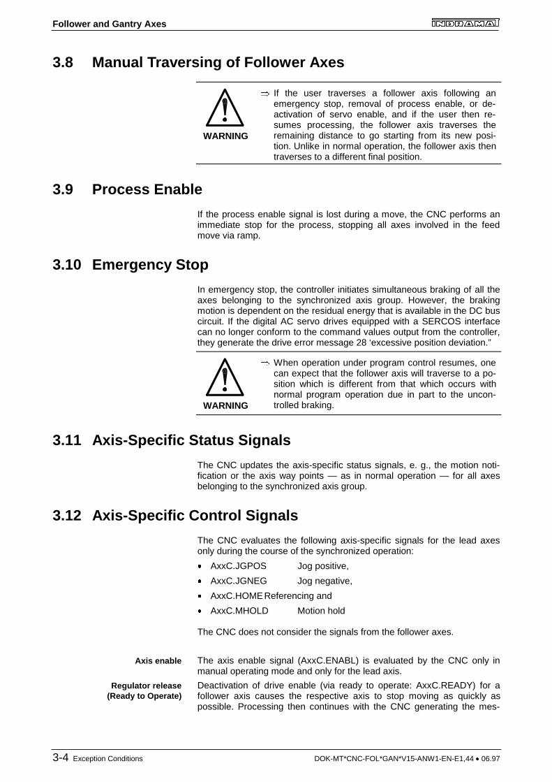
3.8 Manual Traversing of Follower Axes
WARNING
� If the user traverses a follower axis following anemergency stop, removal of process enable, or de-activation of servo enable, and if the user then re-sumes processing, the follower axis traverses theremaining distance to go starting from its new posi-tion. Unlike in normal operation, the follower axis thentraverses to a different final position.
3.9 Process Enable
If the process enable signal is lost during a move, the CNC performs animmediate stop for the process, stopping all axes involved in the feedmove via ramp.
3.10 Emergency Stop
In emergency stop, the controller initiates simultaneous braking of all theaxes belonging to the synchronized axis group. However, the brakingmotion is dependent on the residual energy that is available in the DC buscircuit. If the digital AC servo drives equipped with a SERCOS interfacecan no longer conform to the command values output from the controller,they generate the drive error message 28 ‘excessive position deviation.”
WARNING
� When operation under program control resumes, onecan expect that the follower axis will traverse to a po-sition which is different from that which occurs withnormal program operation due in part to the uncon-trolled braking.
3.11 Axis-Specific Status Signals
The CNC updates the axis-specific status signals, e. g., the motion noti-fication or the axis way points — as in normal operation — for all axesbelonging to the synchronized axis group.
3.12 Axis-Specific Control Signals
The CNC evaluates the following axis-specific signals for the lead axesonly during the course of the synchronized operation:
� AxxC.JGPOS Jog positive,
� AxxC.JGNEG Jog negative,
� AxxC.HOMEReferencing and
� AxxC.MHOLD Motion hold
The CNC does not consider the signals from the follower axes.
The axis enable signal (AxxC.ENABL) is evaluated by the CNC only inmanual operating mode and only for the lead axis.
Deactivation of drive enable (via ready to operate: AxxC.READY) for afollower axis causes the respective axis to stop moving as quickly aspossible. Processing then continues with the CNC generating the mes-
Axis enable
Regulator release(Ready to Operate)
Follower and Gantry Axes
DOK-MT*CNC-FOL*GAN*V15-ANW1-EN-E1,44 � 06.97 Exception Conditions 3-5
sage ‘Inactive axis programmed’ and braking the remaining axes involvedin the process.
The CNC responds in the same way if drive enable is removed from alead axis during a move. The CNC then also immediately brakes thefollower axes as well as the lead axis.
WARNING
� If the SPS removes servo enable from one of the axesin a synchronized axis group, the CNC cancelssynchronized operation so that the given axis can bestopped as quickly as possible.
� When operation under program control resumes, onecan expect that the follower axis will traverse to a po-sition which is different from that which occurs withnormal program operation due in part to the uncon-trolled braking.

Follower and Gantry Axes
DOK-MT*CNC-FOL*GAN*V15-ANW1-EN-E1,44 � 06.97 Machine Data 4-1
4 Machine Data
4.1 Structure of Relevant Machine Data
The machine data for the follower and gantry axes occupy a page 40designated ‘Follower and Gantry Axes.’ The following data structure ispresent in the page 40 for each process and for each synchronized axisgroup:
� 001 Axis Group switched on
� 002 Lead axis in Coord.Sys.
� 003 Follower axis 1 in Coord.Sys
� 004 RPM Lead axis 1 i_LA/FA1
� 005 RPM Follower axis 1 i_LA/FA1
� 006 Direction Follower axis 1
� 007 Follower axis 1 =Gantry axis
� 008 Follower axis 2 in Coord.Sys
� 009 RPM Lead axis 2 i_LA/FA2
� 010 RPM Follower axis 2 i_LA/FA2
� 011 Direction Follower axis 2
� 012 Follower axis 2 =Gantry axis
� 013 Follower axis 3 in Coord.Sys
� 014 RPM Lead axis 3 i_LA/FA3
� 015 RPM Follower axis 3 i_LA/FA3
� 016 Direction Follower axis 3
� 017 Follower axis 3 =Gantry axis
4.2 Modify Machine Data
The individual data elements can be reconfigured at any time from theSPS via the user interface or from the CNC-program provided that thecorresponding synchronized axis group is not active. If the user attemptsto access the data in an active synchronized axis group from the SPS orfrom the user interface, the CNC will generate a process error with mes-sage. If the user attempts to do this in the CNC-program, he will receive aprocess error with message, and the CNC will stop processing.
The synchronized axis groups can only be reconfigured from the userinterface if the user knows the appropriate password and if the respectivegroup is not active.
instruction : If corrupted data are present when a synchronized axis groupis activated, e. g., lead axis specified as 0 in coordinatesystem, the CNC generates a process error with messageand sets the interface signal error (PxxS.ERROR = ‘1’) untilactivation of the group is canceled. If the operator does notcorrect this problem by the next attempt to activate asynchronized axis group, the CNC once again generates aprocess error with message upon the next activation attempt,and sets the gateway signal ‘PxxS.ERROR’.
Follower and Gantry Axes
4-2 Machine Data DOK-MT*CNC-FOL*GAN*V15-ANW1-EN-E1,44 � 06.97
4.3 Description of the Individual Data Elements
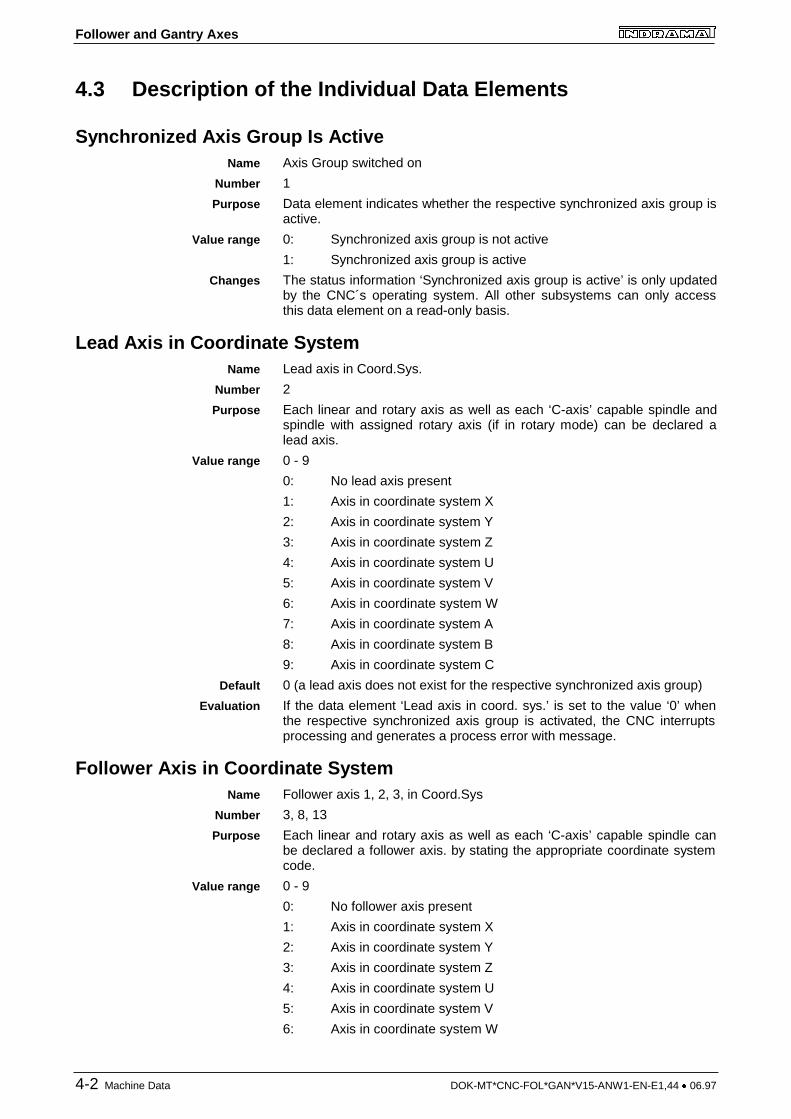
Synchronized Axis Group Is ActiveAxis Group switched on
1
Data element indicates whether the respective synchronized axis group isactive.
0: Synchronized axis group is not active
1: Synchronized axis group is active
The status information ‘Synchronized axis group is active’ is only updatedby the CNC´s operating system. All other subsystems can only accessthis data element on a read-only basis.
Lead Axis in Coordinate SystemLead axis in Coord.Sys.
2
Each linear and rotary axis as well as each ‘C-axis’ capable spindle andspindle with assigned rotary axis (if in rotary mode) can be declared alead axis.
0 - 9
0: No lead axis present
1: Axis in coordinate system X
2: Axis in coordinate system Y
3: Axis in coordinate system Z
4: Axis in coordinate system U
5: Axis in coordinate system V
6: Axis in coordinate system W
7: Axis in coordinate system A
8: Axis in coordinate system B
9: Axis in coordinate system C
0 (a lead axis does not exist for the respective synchronized axis group)
If the data element ‘Lead axis in coord. sys.’ is set to the value ‘0’ whenthe respective synchronized axis group is activated, the CNC interruptsprocessing and generates a process error with message.
Follower Axis in Coordinate SystemFollower axis 1, 2, 3, in Coord.Sys
3, 8, 13
Each linear and rotary axis as well as each ‘C-axis’ capable spindle canbe declared a follower axis. by stating the appropriate coordinate systemcode.
0 - 9
0: No follower axis present
1: Axis in coordinate system X
2: Axis in coordinate system Y
3: Axis in coordinate system Z
4: Axis in coordinate system U
5: Axis in coordinate system V
6: Axis in coordinate system W
Name
Number
Purpose
Value range
Changes
Name
Number
Purpose
Value range
Default
Evaluation
Name
Number
Purpose
Value range
Follower and Gantry Axes
DOK-MT*CNC-FOL*GAN*V15-ANW1-EN-E1,44 � 06.97 Machine Data 4-3
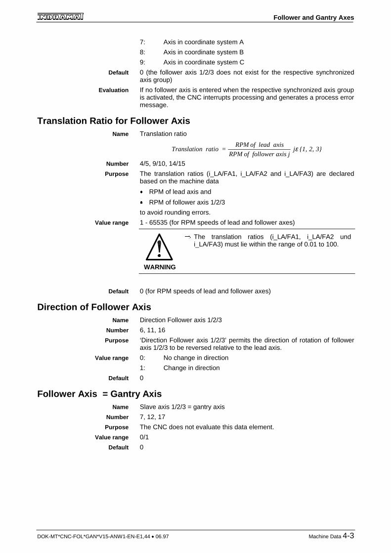
7: Axis in coordinate system A
8: Axis in coordinate system B
9: Axis in coordinate system C
0 (the follower axis 1/2/3 does not exist for the respective synchronizedaxis group)
If no follower axis is entered when the respective synchronized axis groupis activated, the CNC interrupts processing and generates a process errormessage.
Translation Ratio for Follower AxisTranslation ratio
Translation ratio RPM of follow
=RPM of lead axis
er axis j j {1, 2, 3}ε
4/5, 9/10, 14/15
The translation ratios (i_LA/FA1, i_LA/FA2 and i_LA/FA3) are declaredbased on the machine data
� RPM of lead axis and
� RPM of follower axis 1/2/3
to avoid rounding errors.
1 - 65535 (for RPM speeds of lead and follower axes)
WARNING
� The translation ratios (i_LA/FA1, i_LA/FA2 undi_LA/FA3) must lie within the range of 0.01 to 100.
0 (for RPM speeds of lead and follower axes)
Direction of Follower AxisDirection Follower axis 1/2/3
6, 11, 16
‘Direction Follower axis 1/2/3’ permits the direction of rotation of followeraxis 1/2/3 to be reversed relative to the lead axis.
0: No change in direction
1: Change in direction
0
Follower Axis = Gantry AxisSlave axis 1/2/3 = gantry axis
7, 12, 17
The CNC does not evaluate this data element.
0/1
0
Default
Evaluation
Name
Number
Purpose
Value range
Default
Name
Number
Purpose
Value range
Default
Name
Number
Purpose
Value range
Default

Follower and Gantry Axes
DOK-MT*CNC-FOL*GAN*V15-ANW1-EN-E1,44 � 06.97 Gateway Control Signals 5-1
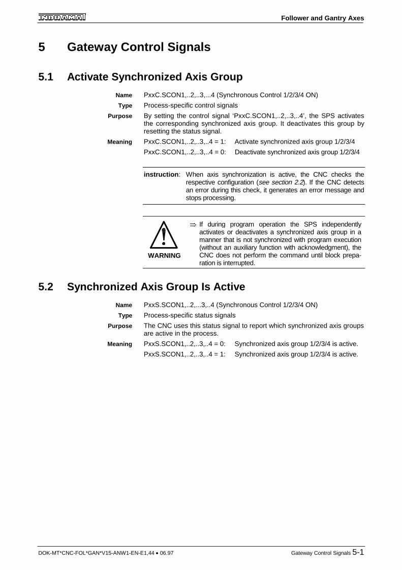
5 Gateway Control Signals
5.1 Activate Synchronized Axis Group
PxxC.SCON1,..2,..3,...4 (Synchronous Control 1/2/3/4 ON)
Process-specific control signals
By setting the control signal ‘PxxC.SCON1,..2,..3,..4’, the SPS activatesthe corresponding synchronized axis group. It deactivates this group byresetting the status signal.
PxxC.SCON1,..2,..3,..4 = 1: Activate synchronized axis group 1/2/3/4
PxxC.SCON1,..2,..3,..4 = 0: Deactivate synchronized axis group 1/2/3/4
instruction : When axis synchronization is active, the CNC checks therespective configuration (see section 2.2). If the CNC detectsan error during this check, it generates an error message andstops processing.
WARNING
� If during program operation the SPS independentlyactivates or deactivates a synchronized axis group in amanner that is not synchronized with program execution(without an auxiliary function with acknowledgment), theCNC does not perform the command until block prepa-ration is interrupted.
5.2 Synchronized Axis Group Is Active
PxxS.SCON1,..2,...3,..4 (Synchronous Control 1/2/3/4 ON)
Process-specific status signals
The CNC uses this status signal to report which synchronized axis groupsare active in the process.
PxxS.SCON1,..2,..3,..4 = 0: Synchronized axis group 1/2/3/4 is active.
PxxS.SCON1,..2,..3,..4 = 1: Synchronized axis group 1/2/3/4 is active.
Name
Type
Purpose
Meaning
Name
Type
Purpose
Meaning

Follower and Gantry Axes
DOK-MT*CNC-FOL*GAN*V15-ANW1-EN-E1,44 � 06.97 Example: Slaving a Follower Rest 6-1
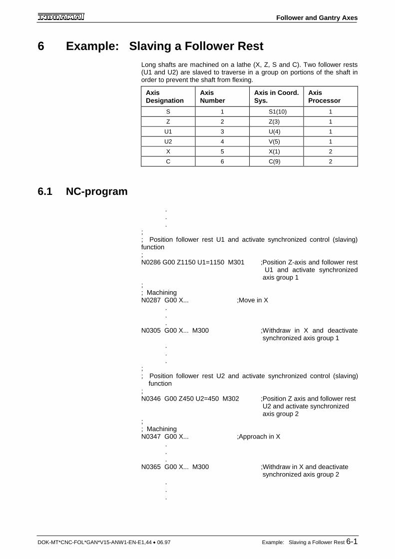
6 Example: Slaving a Follower RestLong shafts are machined on a lathe (X, Z, S and C). Two follower rests(U1 and U2) are slaved to traverse in a group on portions of the shaft inorder to prevent the shaft from flexing.
AxisDesignation
AxisNumber
Axis in Coord.Sys.
AxisProcessor
S 1 S1(10) 1
Z 2 Z(3) 1
U1 3 U(4) 1
U2 4 V(5) 1
X 5 X(1) 2
C 6 C(9) 2
6.1 NC-program
.
.
.;; Position follower rest U1 and activate synchronized control (slaving)function;N0286 G00 Z1150 U1=1150 M301 ;Position Z-axis and follower rest
U1 and activate synchronized axis group 1
;; MachiningN0287 G00 X... ;Move in X
.
.
.N0305 G00 X... M300 ;Withdraw in X and deactivate
synchronized axis group 1...
;; Position follower rest U2 and activate synchronized control (slaving) function;N0346 G00 Z450 U2=450 M302 ;Position Z axis and follower rest
U2 and activate synchronized axis group 2
;; MachiningN0347 G00 X... ;Approach in X
.
.
.N0365 G00 X... M300 ;Withdraw in X and deactivate
synchronized axis group 2...
Follower and Gantry Axes
6-2 Example: Slaving a Follower Rest DOK-MT*CNC-FOL*GAN*V15-ANW1-EN-E1,44 � 06.97
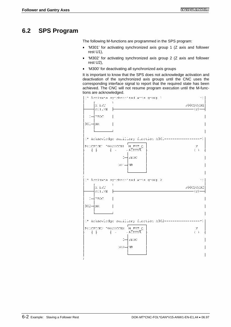
6.2 SPS Program
The following M-functions are programmed in the SPS program:
� ‘M301’ for activating synchronized axis group 1 (Z axis and followerrest U1),
� ‘M302’ for activating synchronized axis group 2 (Z axis and followerrest U2),
� ‘M300’ for deactivating all synchronized axis groups
It is important to know that the SPS does not acknowledge activation anddeactivation of the synchronized axis groups until the CNC uses thecorresponding interface signal to report that the required state has beenachieved. The CNC will not resume program execution until the M-func-tions are acknowledged.��� ������ � ���������� ��� ����� � ��������������������� ���������� �� ��� !" � #$$%&%'(��)����*�%"+,- )���������������������������������������&���*� � � �� $�*#.'% � �� � � ��/$��*(. � �� � � �� 0��������1 �� ���� ��2��34���� ���4�� 5������� �/$���������������������� ���������� ��#$$%&%'(� #$$&&%'(� ��� !"�6 � 7 �)���* )������* )�����*�%"+,- )����������������������� ���*� � � �� $�*#.'% � �� � � �� /$��*(. � �� � � �� 0��������1 �8��� ������ � ���������� ��� ����� 9 ��������������������� ���������� �� ��� !" � #$$%&%'(9�)����*�%"+,- )���������������������������������������&���*� � � �� $�*#.'% � �� � � ��/$9�*(. � �� � � �� 0��������1 �� ���� ��2��34���� ���4�� 5������� �/$9��������������������� ���������� ��#$$%&%'(9 #$$&&%'(9 ��� !"�6 � 7 �)���* )������* )�����*�%"+,- )����������������������� ���*� � � �� $�*#.'% � �� � � �� /$9�*(. � �� � � �� 0��������1 �8
Follower and Gantry Axes
DOK-MT*CNC-FOL*GAN*V15-ANW1-EN-E1,44 � 06.97 Example: Slaving a Follower Rest 6-3
���& �: ��� ������ � �� 9 3��� �/$$ �� � %��4: .�������� ���������� �� ��� !" � #$$%&%'(��)����*�%"+,- )����������;����������������������;�����.���*� � � � � �� $�*#.'% � � � $$%&%'(9�� � � � 0�����.���*�/$$�*(. � � �� � � � �� 0��������1 � �� � ��#$$%%<-�. #$$&-..'. � �)���* )������*=)���������1 �� ���� ��2��34���� ���4�� 5������� �/$$��������������������� ���������� ��#$$%&%'(� #$$&&%'(� #$$%&%'(9 #$$&&%'(9 ��� !"�6 � 7 �)���*=)�������*=)��������*=)��������*=)�����*�%"+,- )� ��*� � � �� $�*#.'% � �� � � �� /$$�*(. � �� � � �� 0��������1 �
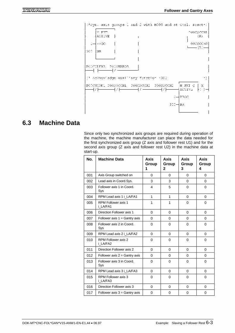
6.3 Machine Data
Since only two synchronized axis groups are required during operation ofthe machine, the machine manufacturer can place the data needed forthe first synchronized axis group (Z axis and follower rest U1) and for thesecond axis group (Z axis and follower rest U2) in the machine data atstart-up.
No. Machine Data AxisGroup1
AxisGroup2
AxisGroup3
AxisGroup4
001 Axis Group switched on 0 0 0 0
002 Lead axis in Coord.Sys. 3 3 0 0
003 Follower axis 1 in Coord.Sys
4 5 0 0
004 RPM Lead axis 1 i_LA/FA1 1 1 0 0
005 RPM Follower axis 1i_LA/FA1
1 1 0 0
006 Direction Follower axis 1 0 0 0 0
007 Follower axis 1 = Gantry axis 0 0 0 0
008 Follower axis 2 in Coord.Sys
0 0 0 0
009 RPM Lead axis 2 i_LA/FA2 0 0 0 0
010 RPM Follower axis 2i_LA/FA2
0 0 0 0
011 Direction Follower axis 2 0 0 0 0
012 Follower axis 2 = Gantry axis 0 0 0 0
013 Follower axis 3 in Coord.Sys
0 0 0 0
014 RPM Lead axis 3 i_LA/FA3 0 0 0 0
015 RPM Follower axis 3i_LA/FA3
0 0 0 0
016 Direction Follower axis 3 0 0 0 0
017 Follower axis 3 = Gantry axis 0 0 0 0

Follower and Gantry Axes
DOK-MT*CNC-FOL*GAN*V15-ANW1-EN-E1,44 � 06.97 Startup Information 7-1
7 Startup Information� The machine builder my define any desired M- or Q-functions to ac-
tivate and deactivate the synchronized axis groups.
� The current torque or the ‘load’ should be shown in the position dis-play. In the case of mechanically linked axes, it is especially importantto monitor the ‘load’.
� It must be noted in conjunction with axis transfer that each axis namein the coordinate system can only be present once in each process.
� The limit switches and reference switches for the lead and follower areto be wired as for the ‘normal’ axes.
WARNING
� Only digital feed drives equipped with the SERCOSinterface and digital main spindles equipped with theSERCOS interface can be used in a synchronized axisgroup.

Follower and Gantry Axes
DOK-MT*CNC-FOL*GAN*V15-ANW1-EN-E1,44 � 06.97 8-1
8 8.1 Index
A
Activate synchronized axis group5-1
C
Coordinate transformationfunction 3-3
D
Data elements 4-2
Direction of follower axis4-3
Follower axis = gantry axis4-3
Follower axis in coord. sys.4-2
Lead axis in coord. sys.4-2
Synchronized axis group isactive 4-2
Translation ratio for followeraxis 4-3
E
Exception conditions 3-1
Axis referencing 3-1
Absolute measuringsystem 3-2
Incremental Measu-ring System 3-2
Multiturn encoderon motor andadditional incre-mental measuringsystem 3-3
Axis transfer 3-1
Axis-specific control 3-4signals 3-4
Axis enable 3-4
Drive enable (ready) 3-4
C-Axis - main spindleand main spindlewith associatedrotary axis 3-3
Emergency stop 3-4
End of program andcontrol reset 3-1
Manual traversing offollower axes 3-4
Process enable 3-4
Traversing to limit stop3-3
G
Gateway control signals 5-1
L
Legal axis types2-2
Legal Configurations 2-1
Linking of lead and follower axes2-1
M
Machine data 4-1; 6-3
Modify machine data 4-1
N
NC Program 6-1
NC programming 2-2
P
Process operating modeselection 3-3
S
Scope of the Function 2-1
Slaving a follower rest 6-1
SPS Program 6-2
Steps in the SynchronizedControl Operation 2-3
Structure of relevant machinedata 4-1
Synchronized axis group isactive 5-1
T
Tests Performed at the start ofand during synchronousoperation 2-3

Follower and Gantry Axes
DOK-MT*CNC-FOL*GAN*V15-ANW1-EN-E1,44 � 06.97 List of Illustrations 9-1
9 List of IllustrationsFig. 1-1: Example of synchronizing lead and follower axes
(no mechanical coupling is present). ........................................1-1Fig. 1-2: Example of gantry axes
(a mechanical coupling is present). ..........................................1-2Fig. 2-1: Legal synchronized axis groups within a process for axis
synchronization and for gantry mode........................................2-2

Follower and Gantry Axes
DOK-MT*CNC-FOL*GAN*V15-ANW1-EN-E1,44 � 06.97 Customer Service
Customer ServiceGermany
Vertriebsgebiet Mitte
INDRAMAT GmbHD-97816 Lohr am MainBgm.-Dr.-Nebel-Str. 2
Telefon: 09352/40-0Telefax: 09352/40-4885
Vertriebsgebiet Ost
INDRAMAT GmbHD-09120 ChemnitzBeckerstraße 31
Telefon: 0371/3555-0Telefax: 0371/3555-230
Vertriebsgebiet West
INDRAMAT GmbHD-40849 RatingenHansastraße 25
Telefon: 02102/4318-0Telefax: 02102/41315
Vertriebsgebiet Nord
INDRAMAT GmbHD-22085 HamburgFährhausstraße 11
Telefon: 040/227126-16Telefax: 040/227126-15
Vertriebsgebiet Süd
INDRAMAT GmbHD-80339 MünchenRidlerstraße 75
Telefon: 089/540138-30Telefax: 089/540138-10
Vertriebsgebiet Südwest
INDRAMAT GmbHD-71229 LeonbergBöblinger Straße 25
Telefon: 07152/972-6Telefax: 07152/972-727
INDRAMAT Service-Hotline
INDRAMAT GmbHTelefon: D-0172/660 040 6
-oder-
Telefon: D-0171/333 882 6
Customer Service in Germany
EuropeAustria
G.L.Rexroth Ges.m.b.H.Geschäftsbereich INDRAMATA-1140 WienHägelingasse 3
Telefon: 1/9852540-400Telefax:1/9852540-93
Austria
G.L.Rexroth Ges.m.b.H.Geschäftsbereich INDRAMATA-4061 PaschingRandlstraße 14
Telefon: 07229/4401-36Telefax: 07229/4401-80
Belgium
Mannesmann Rexroth N.V.-S.A.Geschäftsbereich INDRAMATB-1740 TernatIndustrielaan 8
Telefon: 02/5823180Telefax: 02/5824310
Denmark
BEC Elektronik ASDK-8900 RandersZinkvej 6
Telefon: 086/447866Telefax: 086/447160
England
Mannesmann Rexroth Ltd.INDRAMAT DivisionCirencester, Glos GL7 1YG4 Esland Place, Love Lane
Telefon: 01285/658671Telefax: 01285/654991
Finnland
Rexroth Mecman OYSF-01720 VantaaRiihimiehentie 3
Telefon: 0/848511Telefax: 0/846387
France
Rexroth - Sigma S.A.Division INDRAMATF-92632 Gennevilliers CedexParc des Barbanniers 4,Place du Village
Telefon: 1/41475430Telefax: 1/47946941
France
Rexroth - Sigma S.A.Division INDRAMATF-69634 Venissieux - Cx91, Bd 1 Joliot Curie
Telefon: 78785256Telefax: 78785231
France
Rexroth - Sigma S.A.Division INDRAMATF-31100 Toulouse270, Avenue de lardenne
Telefon: 61499519Telefax: 61310041
Italy
Rexroth S.p.A.Divisione INDRAMATI-20063 Cernusco S/N.MIVia G. Di Vittoria, 1
Telefon: 02/92365-270Telefax: 02/92108069
Italy
Rexroth S.p.A. DivisioneINDRAMATVia Borgomanero, 11I-10145 Torino
Telefon: 011/7712230Telefax: 011/7710190
Netherlands
Hydraudyne Hydrauliek B.V.Kruisbroeksestraat 1aP.O. Box 32NL-5280 AA Boxtel
Telefon: 04116/51951Telefax: 04116/51483
Spain
Rexroth S.A.Centro Industrial SantiagoObradors s/nE-08130 Santa Perpetua deMogoda (Barcelona)
Telefon: 03/718 68 51Telex: 591 81Telefax: 03/718 98 62
Spain
Goimendi S.A.División IndramatJolastokieta (Herrera)Apartado 11 37San Sebastion, 20017
Telefon: 043/40 01 63Telex: 361 72Telefax: 043/39 93 95
Sweden
AB Rexroth MecmanINDRAMAT DivisionVaruvägen 7S-125 81 Stockholm
Telefon: 08/727 92 00Telefax: 08/64 73 277
Switzerland
Rexroth SADépartement INDRAMATChemin de l`Ecole 6CH-1036 Sullens
Telefon: 021/731 43 77Telefax: 021/731 46 78
Switzerland
Rexroth AGGeeschäftsbereich INDRAMATGewerbestraße 3CH-8500 Frauenfeld
Telefon: 052/720 21 00Telefax: 052/720 21 11
Russia
Tschudnenko E.B.Arsenia 22153000 IvanovoRußland
Telefon: 093/22 39 633
Customer Service in Europe
Follower and Gantry Axes
Customer Service DOK-MT*CNC-FOL*GAN*V15-ANW1-EN-E1,44 � 06.97
Outside of EuropeArgentina
Mannesmann Rexroth S.A.I.C.Division INDRAMATAcassusso 48 41/71605 Munro (Buenos Aires)Argentina
Telefon: 01/756 01 40 01/756 02 40Telex: 262 66 rexro arTelefax: 01/756 01 36
Argentina
NakaseAsesoramiento TecnicoDiaz Velez 29291636 Olivos(Provincia de Buenos Aires)ArgentinaArgentina
Telefon 01/790 52 30
Australia
Australian Industrial MacheneryServices Pty. Ltd.Unit 3/45 Horne STCampbellfield VIC 2061Australia
Telefon: 03/93 59 0228Telefax: 03/93 59 02886
Brazil
Mannesmann Rexroth AutomaçãoLtda.Divisão INDRAMATRua Georg Rexroth, 609Vila Padre AnchietaBR-09.951-250 Diadema-SPCaixa Postal 377BR-09.901-970 Diadema-SP
Telefon: 011/745 90 65 011/745 90 70Telefax: 011/745 90 50
Canada
Basic Technologies CorporationBurlington Division3426 Mainway DriveBurlington, OntarioCanada L7M 1A8
Telefon: 905/335-55 11Telefax: 905/335-41 84
China
Rexroth (China) Ldt.Shanghai OfficeRoom 206Shanghai Intern. Trade Centre2200 Yanan Xi LuShanghai 200335P.R. China
Telefon: 021/627 55 333Telefax: 021/627 55 666
China
Rexroth (China) Ldt.Shanghai Parts & Service Centre199 Wu Cao Road, Hua CaoMinhang DistrictShanghai 201 103P.R. China
Telefon: 021/622 00 058Telefax: 021/622 00 068
China
Rexroth (China) Ldt.1430 China World Trade Centre1, Jianguomenwai AvenueBeijing 100004P.R. China
Telefon: 010/50 50 380Telefax: 010/50 50 379
China
Rexroth (China) Ldt.A-5F., 123 Lian Shan StreetSha He Kou DistrictDalian 116 023P.R. China
Telefon: 0411/46 78 930Telefax: 0411/46 78 932
Honkong
Rexroth (China) Ldt.19 Cheung Shun Street1st Floor, Cheung Sha Wan,Kowloon, Honkong
Telefon: 741 13 51/-54 und 741 14 30Telex: 3346 17 GL REX HXTelefax: 786 40 19 786 07 33
India
Mannesmann Rexroth (India) Ltd.INDRAMAT DivisionPlot. 96, Phase IIIPeenya Industrial AreaBangalore - 560058
Telefon: 80/839 21 01 80/839 73 74Telex: 845 5028 RexBTelefax: 80/839 43 45
Japan
Rexroth Co., Ltd.INDRAMAT DivisionI.R. BuildingNakamachidai 4-26-44Tsuzuki-ku, Yokohama 226Japan
Telefon: 045/942-72 10Telefax: 045/942-03 41
Korea
Rexroth-Seki Co Ltd.1500-12 Da-Dae-DongSaha-Gu, Pusan, 604-050
Telefon: 051/264 90 01Telefax: 051/264 90 10
Korea
Seo Chang Corporation Ltd.Room 903, Jeail Building44-35 Yoido-DongYoungdeungpo-KuSeoul, Korea
Telefon: 02/780-82 07 ~9Telefax: 02/784-54 08
Mexico
Motorización yDiseño de Controles, S.A. de C.V.Av. Dr. Gustavo Baz No. 288Col. Parque Industrial la IomaApartado Postal No. 31854060 TlalnepantlaEstado de Mexico
Telefon: 5/397 86 44Telefax: 5/398 98 88
USA
Rexroth CorporationINDRAMAT Division5150 Prairie Stone ParkwayHoffman Estates, Illinois 60192
Telefon: 847/645-36 00Telefax: 857/645-62 01
USA
Rexroth CorporationINDRAMAT Division2110 Austin AvenueRochester Hills, Michigan 48309
Telefon: 810/853-82 90Telefax: 810/853-82 90
Customer Service outside of Europe
Follower and Gantry Axes
DOK-MT*CNC-FOL*GAN*V15-ANW1-EN-E1,44 � 06.97
Notes

Indramat