Embed Size (px)
Citation preview
GEMALTO.COM/M2M
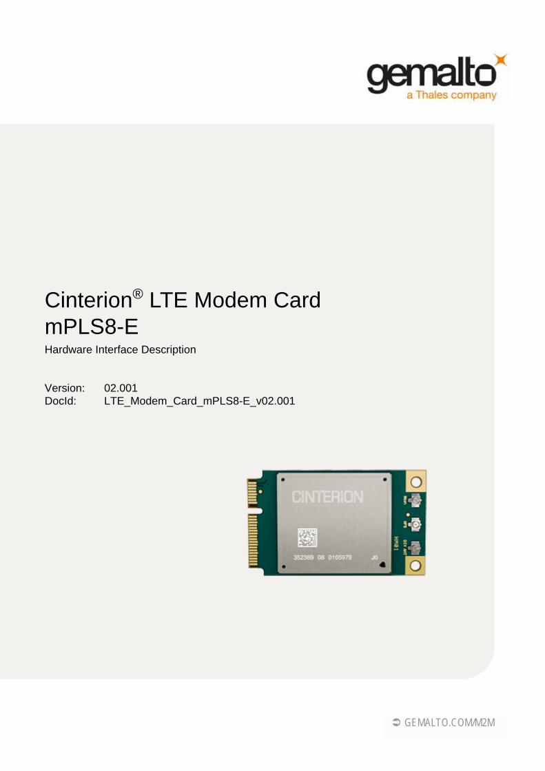
Cinterion® LTE Modem Card mPLS8-EHardware Interface Description
Version: 02.001DocId: LTE_Modem_Card_mPLS8-E_v02.001
GENERAL NOTE THIS DOCUMENT CONTAINS INFORMATION ON GEMALTO PRODUCTS. GEMALTO M2MRESERVES THE RIGHT TO MAKE CHANGES TO THE PRODUCTS DESCRIBED HEREIN. THESPECIFICATIONS IN THIS DOCUMENT ARE SUBJECT TO CHANGE AT THE DISCRETION OFGEMALTO M2M. THE PRODUCT AND THIS DOCUMENT ARE PROVIDED ON AN "AS IS" BASISONLY AND MAY CONTAIN DEFICIENCIES OR INADEQUACIES. GEMALTO M2M DOES NOTASSUME ANY LIABILITY FOR INFORMATION PROVIDED IN THE DOCUMENT OR ARISING OUT OFTHE APPLICATION OR USE OF ANY PRODUCT DESCRIBED HEREIN.
GEMALTO M2M GRANTS A NON-EXCLUSIVE RIGHT TO USE THE DOCUMENT. THE RECIPIENTSHALL NOT COPY, MODIFY, DISCLOSE OR REPRODUCE THE DOCUMENT EXCEPT AS SPECIFI-CALLY AUTHORIZED BY GEMALTO M2M.
Copyright © 2019, Gemalto M2M GmbH, a Thales Company
Trademark NoticeGemalto, the Gemalto logo, are trademarks and service marks of Gemalto and are registered in certaincountries. Microsoft and Windows are either registered trademarks or trademarks of Microsoft Corporation in theUnited States and/or other countries. PCI Express is a trademark of PCI-SIG. All other registered trade-marks or trademarks mentioned in this document are property of their respective owners.
LTE_Modem_Card_mPLS8-E_v02.001 2019-07-12Public / Released
Cinterion® LTE Modem Card mPLS8-E Hardware Interface Description
Page 2 of 40
Document Name: Cinterion® LTE Modem Card mPLS8-E Hardware Interface Description
Version: 02.001
Date: 2019-07-12
DocId: LTE_Modem_Card_mPLS8-E_v02.001
Status Public / Released
Cinterion® LTE Modem Card mPLS8-E Hardware Interface Description
LTE_Modem_Card_mPLS8-E_v02.001 2019-07-12Public / Released
Page 3 of 40
Contents
0 Document History ...................................................................................................... 6
1 Introduction ................................................................................................................. 71.1 Ordering Information .......................................................................................... 71.2 Related Documents ........................................................................................... 71.3 Terms and Abbreviations ................................................................................... 7
2 Product Concept ......................................................................................................... 92.1 Key Features at a Glance ................................................................................ 102.2 System Overview ............................................................................................. 132.3 Mechanical Dimensions ................................................................................... 13
3 Application Connector Interface.............................................................................. 143.1 Pin Assignments and Electrical Description..................................................... 143.2 Characteristics ................................................................................................. 19
3.2.1 Power Supply and Ground.................................................................. 193.2.2 USB Interface...................................................................................... 193.2.3 SIM/UICC Interface............................................................................. 193.2.4 W_DISABLE1# Signal ........................................................................ 203.2.5 PERST# Signal ................................................................................... 203.2.6 WAKE# Signal .................................................................................... 20
4 Antenna Interface...................................................................................................... 214.1 GSM/UMTS/LTE Antenna Interface................................................................. 21
4.1.1 Antenna Interface Specification .......................................................... 214.2 GNSS Antenna Interface ................................................................................. 26
4.2.1 GNSS Interface Characteristics .......................................................... 264.3 GNSS Interface Characteristics ....................................................................... 28
5 Operation ................................................................................................................... 295.1 Operating Modes ............................................................................................. 295.2 Power Up/Power Down Scenarios................................................................... 30
5.2.1 Turn LTE Modem Card mPLS8-E on.................................................. 305.2.2 Reset/Restart LTE Modem Card mPLS8-E ........................................ 305.2.3 Turn LTE Modem Card mPLS8-E off .................................................. 30
5.3 Automatic thermal shutdown............................................................................ 315.4 Operating Temperatures.................................................................................. 325.5 Power Supply Ratings...................................................................................... 335.6 Electrostatic Discharge .................................................................................... 355.7 Reliability Characteristics................................................................................. 365.8 Approval Information........................................................................................ 37
5.8.1 Directives and Standards.................................................................... 375.9 Safety Precaution Notes .................................................................................. 40
Cinterion® LTE Modem Card mPLS8-E Hardware Interface Description
LTE_Modem_Card_mPLS8-E_v02.001 2019-07-12Public / Released
Page 4 of 40
Tables
Table 1: LTE Modem Card mPLS8-E ............................................................................ 7Table 2: Pin assignments............................................................................................. 14Table 3: Electrical description of connector interface pins ........................................... 16Table 4: Signals of the SIM interface ........................................................................... 19Table 5: Return loss in the active band........................................................................ 21Table 6: RF Antenna interface GSM/UMTS/LTE (at operating temperature range) .... 21Table 7: GNSS properties ............................................................................................ 26Table 8: Power supply for active GNSS antenna......................................................... 27Table 9: GNSS properties ............................................................................................ 28Table 10: Power supply for active GNSS antenna......................................................... 28Table 11: Overview of operating modes ........................................................................ 29Table 12: Temperature characteristics........................................................................... 32Table 13: Current consumption ratings .......................................................................... 33Table 14: Electrostatic values ........................................................................................ 35Table 15: Summary of reliability test conditions............................................................. 36Table 16: Directives ....................................................................................................... 37Table 17: Standards of European type approval............................................................ 37Table 18: Requirements of quality ................................................................................. 38Table 19: Standards of the Ministry of Information Industry of the People’s Republic
of China.......................................................................................................... 38Table 20: Toxic or hazardous substances or elements with defined concentration
limits ............................................................................................................... 39
Cinterion® LTE Modem Card mPLS8-E Hardware Interface Description
LTE_Modem_Card_mPLS8-E_v02.001 2019-07-12Public / Released
Page 5 of 40
Figures
Figure 1: LTE Modem Card mPLS8-E top view .............................................................. 9Figure 2: LTE Modem Card mPLS8-E bottom view ........................................................ 9Figure 3: LTE Modem Card mPLS8-E system overview............................................... 13Figure 4: LTE Modem Card mPLS8-E mechanical dimensions (height)....................... 13Figure 5: Supply voltage for active GNSS antenna....................................................... 26
Cinterion® LTE Modem Card mPLS8-E Hardware Interface Description
LTE_Modem_Card_mPLS8-E_v02.001 2019-07-12Public / Released
Page 6 of 40
0 Document History
New document: "LTE Modem Card mPLS8-E Hardware Interface Description” Version 02.001Previous document: "LTE Modem Card mPLS8-E Hardware Interface Description” Version 02.000
New document: "LTE Modem Card mPLS8-E Hardware Interface Description” Version 02.000
Chapter What is new
2 Updated Figure 1 and Figure 2
2.1 hight of LTE Modem Card changed to 4.7mm
5.5 Revised Table 13, adding power consumption values
Chapter What is new
-- Initial document setup.
Cinterion® LTE Modem Card mPLS8-E Hardware Interface Description
LTE_Modem_Card_mPLS8-E_v02.001 2019-07-12Public / Released
Page 7 of 40
1 Introduction
This document1 describes the hardware of the Cinterion® LTE Modem Card mPLS8-E product. It helps you quickly retrieve interface specifications, electrical and mechanical details, and in-formation on the requirements to be considered for integrating further components.
1.1 Ordering Information
1.2 Related Documents
[1] PLS8-E AT Command Set Specification [2] PLS8-E Hardware Interface Specification[3] PLS8-E Release Note[4] PCI Express® Mini Card Electromechanical Specification, Revision 2.1, December 9, 2016
1.3 Terms and Abbreviations
1. The document is effective only if listed in the appropriate Release Notes as part of the technical docu-mentation delivered with your Gemalto M2M product.
Table 1: LTE Modem Card mPLS8-E
Product Module Ordering information
LTE Modem Card mPLS8-E PLS8-E Order number: L30960-N3270-A300
Abbreviation Description
3FF Third Form Factor
3GPP 3rd Generation Partnership Project
CE Conformité Européene (European Conformity)
CSD Circuit Switched Data
CTM Cellular Text Telephone Modem
ETS European Telecommunication Standard
FCC Federal Communications Commission (U.S.)
GPRS General Packet Radio Service
GSM Global Standard for Mobile Communications
HSPA High Speed Packet Access
HSDPA High Speed Download Packet Access
I/O Input/Output
Cinterion® LTE Modem Card mPLS8-E Hardware Interface Description
LTE_Modem_Card_mPLS8-E_v02.001 2019-07-12Public / Released
Page 8 of 40
IC Integrated Circuit
IEC International Electrotechnical Commission
ISO International Standards Organization
ITU International Telecommunications Union
LED Light Emitting Diode
Mbps Mbits per second
MFF2 M2M UICC Form Factor 2
MMI Man Machine Interface
MNO Mobile Network Operator
MO Mobile Originated
MT Mobile Terminated
PBCCH Packet Switched Broadcast Control Channel
PCI Peripheral Component Interconnect (personal computer bus)
PDU Protocol Data Unit
PIN Personal Identification Number
PPP Point-to-point protocol
R&TTE Radio and Telecommunication Terminal Equipment
RF Radio Frequency
RLP Radio Link Protocol
RoHS Restriction of the use of certain hazardous substances in electrical and electronic equipment.
SAR Specific Absorption Rate
SIM Subscriber Identification Module
SMS Short Message Service
TTY Text Telephone
UICC Universal Integrated Circuit Card
UMTS Universal Mobile Telecommunications System
USB Universal Serial Bus
USSD Unstructured Supplementary Service Data
Abbreviation Description
Cinterion® LTE Modem Card mPLS8-E Hardware Interface Description
LTE_Modem_Card_mPLS8-E_v02.001 2019-07-12Public / Released
Page 9 of 40
2 Product Concept
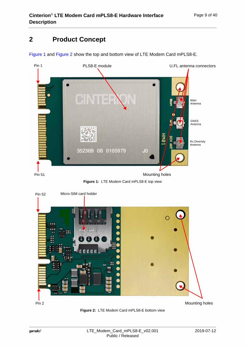
Figure 1 and Figure 2 show the top and bottom view of LTE Modem Card mPLS8-E.
Figure 1: LTE Modem Card mPLS8-E top view
Figure 2: LTE Modem Card mPLS8-E bottom view
U.FL antenna connectorsPLS8-E module
Mounting holes
Pin 1
Pin 51
MainAntenna
Rx DiversityAntenna
GNSSAntenna
Mounting holes
Pin 52
Pin 2
Micro-SIM card holder
Cinterion® LTE Modem Card mPLS8-E Hardware Interface Description
LTE_Modem_Card_mPLS8-E_v02.001 2019-07-12Public / Released
Page 10 of 40
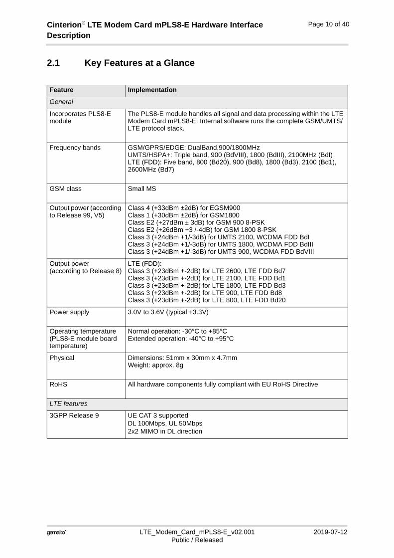
2.1 Key Features at a Glance
Feature Implementation
General
Incorporates PLS8-E module
The PLS8-E module handles all signal and data processing within the LTE Modem Card mPLS8-E. Internal software runs the complete GSM/UMTS/LTE protocol stack.
Frequency bands GSM/GPRS/EDGE: DualBand,900/1800MHzUMTS/HSPA+: Triple band, 900 (BdVIII), 1800 (BdIII), 2100MHz (BdI)LTE (FDD): Five band, 800 (Bd20), 900 (Bd8), 1800 (Bd3), 2100 (Bd1), 2600MHz (Bd7)
GSM class Small MS
Output power (according to Release 99, V5)
Class 4 (+33dBm ±2dB) for EGSM900Class 1 (+30dBm ±2dB) for GSM1800Class E2 (+27dBm ± 3dB) for GSM 900 8-PSKClass E2 (+26dBm +3 /-4dB) for GSM 1800 8-PSKClass 3 (+24dBm +1/-3dB) for UMTS 2100, WCDMA FDD BdIClass 3 (+24dBm +1/-3dB) for UMTS 1800, WCDMA FDD BdIIIClass 3 (+24dBm +1/-3dB) for UMTS 900, WCDMA FDD BdVIII
Output power (according to Release 8)
LTE (FDD):Class 3 (+23dBm +-2dB) for LTE 2600, LTE FDD Bd7Class 3 (+23dBm +-2dB) for LTE 2100, LTE FDD Bd1Class 3 (+23dBm +-2dB) for LTE 1800, LTE FDD Bd3Class 3 (+23dBm +-2dB) for LTE 900, LTE FDD Bd8Class 3 (+23dBm +-2dB) for LTE 800, LTE FDD Bd20
Power supply 3.0V to 3.6V (typical +3.3V)
Operating temperature(PLS8-E module board temperature)
Normal operation: -30°C to +85°CExtended operation: -40°C to +95°C
Physical Dimensions: 51mm x 30mm x 4.7mmWeight: approx. 8g
RoHS All hardware components fully compliant with EU RoHS Directive
LTE features
3GPP Release 9 UE CAT 3 supportedDL 100Mbps, UL 50Mbps2x2 MIMO in DL direction
Cinterion® LTE Modem Card mPLS8-E Hardware Interface Description
LTE_Modem_Card_mPLS8-E_v02.001 2019-07-12Public / Released
Page 11 of 40
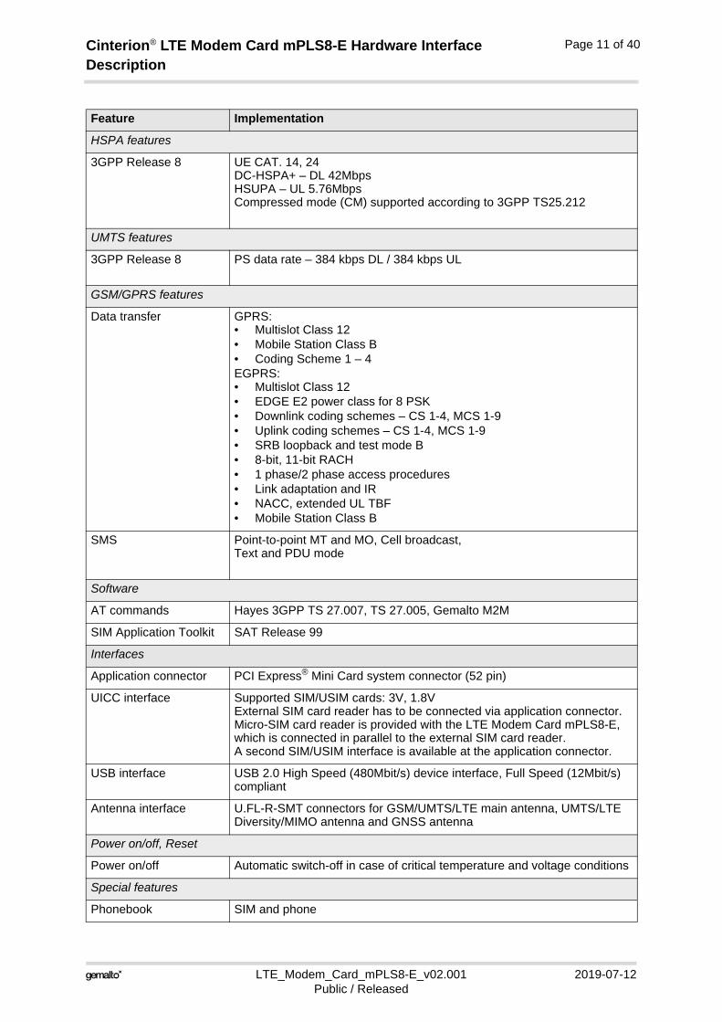
HSPA features
3GPP Release 8 UE CAT. 14, 24DC-HSPA+ – DL 42MbpsHSUPA – UL 5.76Mbps Compressed mode (CM) supported according to 3GPP TS25.212
UMTS features
3GPP Release 8 PS data rate – 384 kbps DL / 384 kbps UL
GSM/GPRS features
Data transfer GPRS:• Multislot Class 12• Mobile Station Class B• Coding Scheme 1 – 4EGPRS:• Multislot Class 12• EDGE E2 power class for 8 PSK• Downlink coding schemes – CS 1-4, MCS 1-9• Uplink coding schemes – CS 1-4, MCS 1-9• SRB loopback and test mode B• 8-bit, 11-bit RACH• 1 phase/2 phase access procedures• Link adaptation and IR• NACC, extended UL TBF• Mobile Station Class B
SMS Point-to-point MT and MO, Cell broadcast, Text and PDU mode
Software
AT commands Hayes 3GPP TS 27.007, TS 27.005, Gemalto M2M
SIM Application Toolkit SAT Release 99
Interfaces
Application connector PCI Express® Mini Card system connector (52 pin)
UICC interface Supported SIM/USIM cards: 3V, 1.8VExternal SIM card reader has to be connected via application connector.Micro-SIM card reader is provided with the LTE Modem Card mPLS8-E, which is connected in parallel to the external SIM card reader.A second SIM/USIM interface is available at the application connector.
USB interface USB 2.0 High Speed (480Mbit/s) device interface, Full Speed (12Mbit/s) compliant
Antenna interface U.FL-R-SMT connectors for GSM/UMTS/LTE main antenna, UMTS/LTE Diversity/MIMO antenna and GNSS antenna
Power on/off, Reset
Power on/off Automatic switch-off in case of critical temperature and voltage conditions
Special features
Phonebook SIM and phone
Feature Implementation
Cinterion® LTE Modem Card mPLS8-E Hardware Interface Description
LTE_Modem_Card_mPLS8-E_v02.001 2019-07-12Public / Released
Page 12 of 40
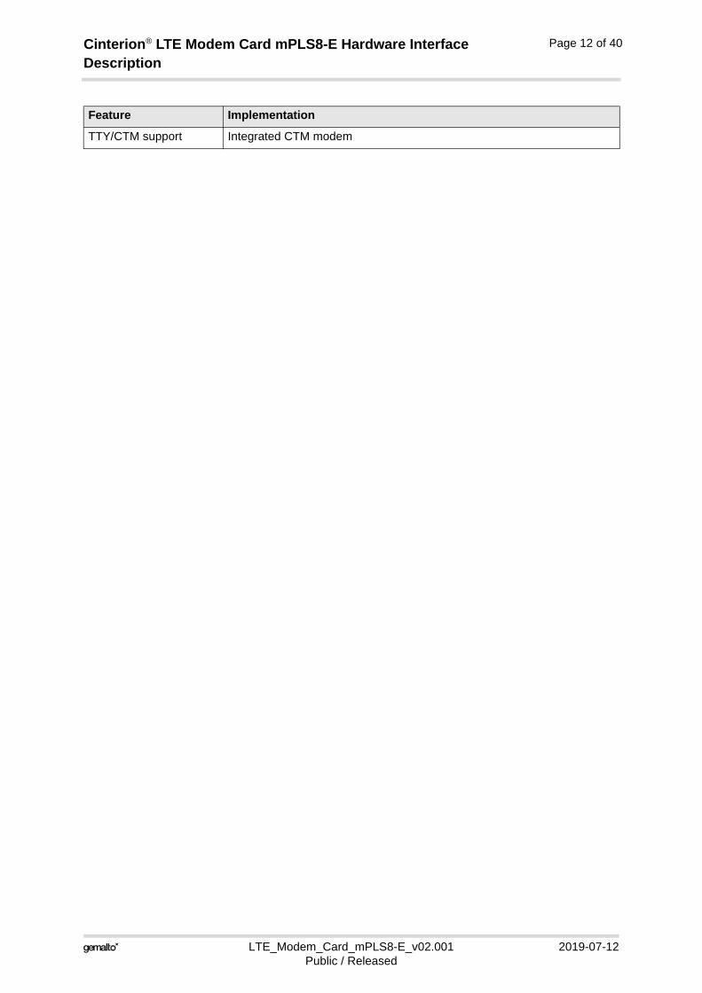
TTY/CTM support Integrated CTM modem
Feature Implementation
Cinterion® LTE Modem Card mPLS8-E Hardware Interface Description
LTE_Modem_Card_mPLS8-E_v02.001 2019-07-12Public / Released
Page 13 of 40
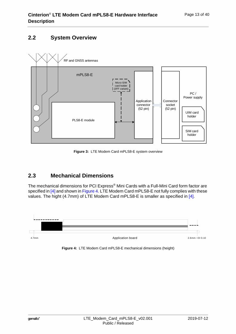
2.2 System Overview
Figure 3: LTE Modem Card mPLS8-E system overview
2.3 Mechanical Dimensions
The mechanical dimensions for PCI Express® Mini Cards with a Full-Mini Card form factor are specified in [4] and shown in Figure 4. LTE Modem Card mPLS8-E not fully complies with these values. The hight (4.7mm) of LTE Modem Card mPLS8-E is smaller as specified in [4].
Figure 4: LTE Modem Card mPLS8-E mechanical dimensions (height)
PLS8-E module
Application connector (52 pin)
PC / Power supply
SIM card holder
RF and GNSS antennas
Connectorsocket (52 pin)
mPLS8-E
Micro-SIMcard holder
(3FF variant)
UIM card holder
Application board4.7mm 2.6mm +0/-0.10
Cinterion® LTE Modem Card mPLS8-E Hardware Interface Description
LTE_Modem_Card_mPLS8-E_v02.001 2019-07-12Public / Released
Page 14 of 40
3 Application Connector Interface
3.1 Pin Assignments and Electrical Description
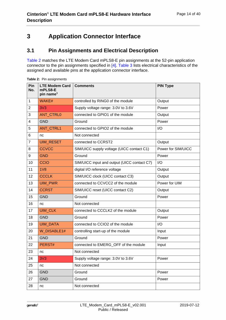
Table 2 matches the LTE Modem Card mPLS8-E pin assignments at the 52-pin application connector to the pin assignments specified in [4]. Table 3 lists electrical characteristics of the assigned and available pins at the application connector interface.
Table 2: Pin assignments
Pin No.
LTE Modem Card mPLS8-Epin name1
Comments PIN Type
1 WAKE# controlled by RING0 of the module Output
2 3V3 Supply voltage range: 3.0V to 3.6V Power
3 ANT_CTRL0 connected to GPIO1 of the module Output
4 GND Ground Power
5 ANT_CTRL1 connected to GPIO2 of the module I/O
6 nc Not connected
7 UIM_RESET connected to CCRST2 Output
8 CCVCC SIM/UICC supply voltage (UICC contact C1) Power for SIM/UICC
9 GND Ground Power
10 CCIO SIM/UICC input and output (UICC contact C7) I/O
11 1V8 digital I/O reference voltage Output
12 CCCLK SIM/UICC clock (UICC contact C3) Output
13 UIM_PWR connected to CCVCC2 of the module Power for UIM
14 CCRST SIM/UICC reset (UICC contact C2) Output
15 GND Ground Power
16 nc Not connected
17 UIM_CLK connected to CCCLK2 of the module Output
18 GND Ground Power
19 UIM_DATA connected to CCIO2 of the module I/O
20 W_DISABLE1# controlling start-up of the module Input
21 GND Ground Power
22 PERST# connected to EMERG_OFF of the module Input
23 nc Not connected
24 3V3 Supply voltage range: 3.0V to 3.6V Power
25 nc Not connected
26 GND Ground Power
27 GND Ground Power
28 nc Not connected
Cinterion® LTE Modem Card mPLS8-E Hardware Interface Description
LTE_Modem_Card_mPLS8-E_v02.001 2019-07-12Public / Released
Page 15 of 40
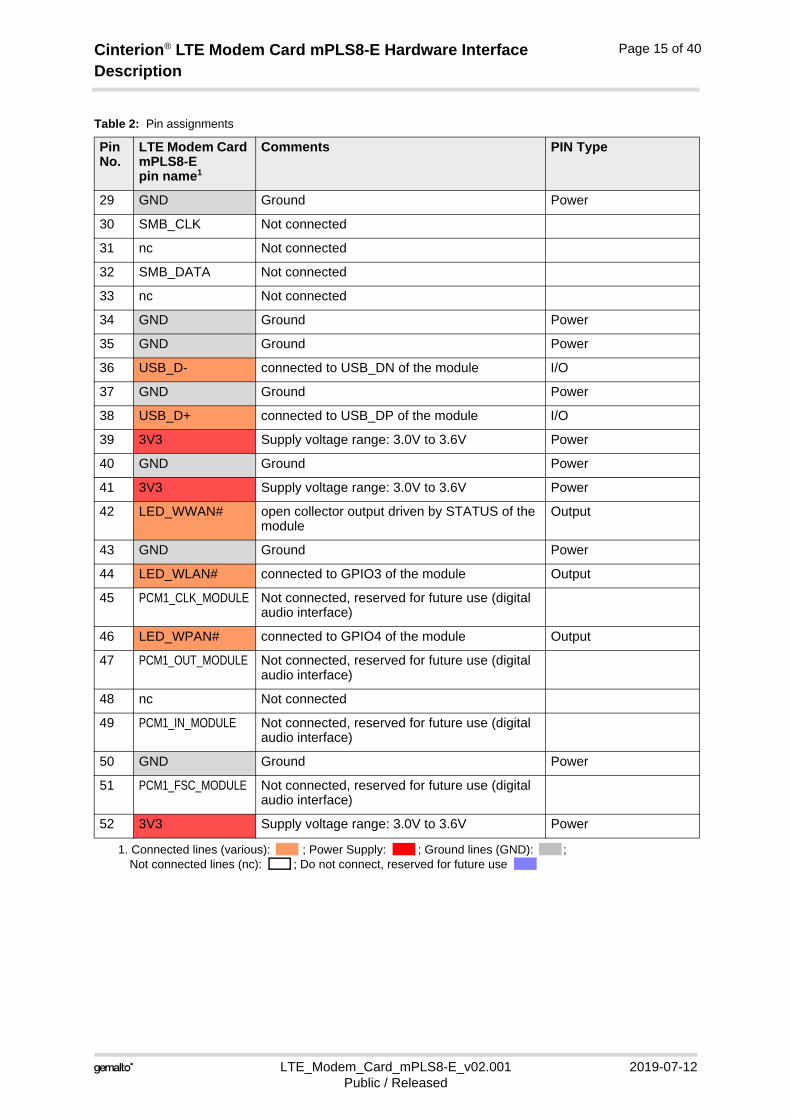
29 GND Ground Power
30 SMB_CLK Not connected
31 nc Not connected
32 SMB_DATA Not connected
33 nc Not connected
34 GND Ground Power
35 GND Ground Power
36 USB_D- connected to USB_DN of the module I/O
37 GND Ground Power
38 USB_D+ connected to USB_DP of the module I/O
39 3V3 Supply voltage range: 3.0V to 3.6V Power
40 GND Ground Power
41 3V3 Supply voltage range: 3.0V to 3.6V Power
42 LED_WWAN# open collector output driven by STATUS of the module
Output
43 GND Ground Power
44 LED_WLAN# connected to GPIO3 of the module Output
45 PCM1_CLK_MODULE Not connected, reserved for future use (digital audio interface)
46 LED_WPAN# connected to GPIO4 of the module Output
47 PCM1_OUT_MODULE Not connected, reserved for future use (digital audio interface)
48 nc Not connected
49 PCM1_IN_MODULE Not connected, reserved for future use (digital audio interface)
50 GND Ground Power
51 PCM1_FSC_MODULE Not connected, reserved for future use (digital audio interface)
52 3V3 Supply voltage range: 3.0V to 3.6V Power
1. Connected lines (various): ; Power Supply: ; Ground lines (GND): ; Not connected lines (nc): ; Do not connect, reserved for future use
Table 2: Pin assignments
Pin No.
LTE Modem Card mPLS8-Epin name1
Comments PIN Type
Cinterion® LTE Modem Card mPLS8-E Hardware Interface Description
LTE_Modem_Card_mPLS8-E_v02.001 2019-07-12Public / Released
Page 16 of 40
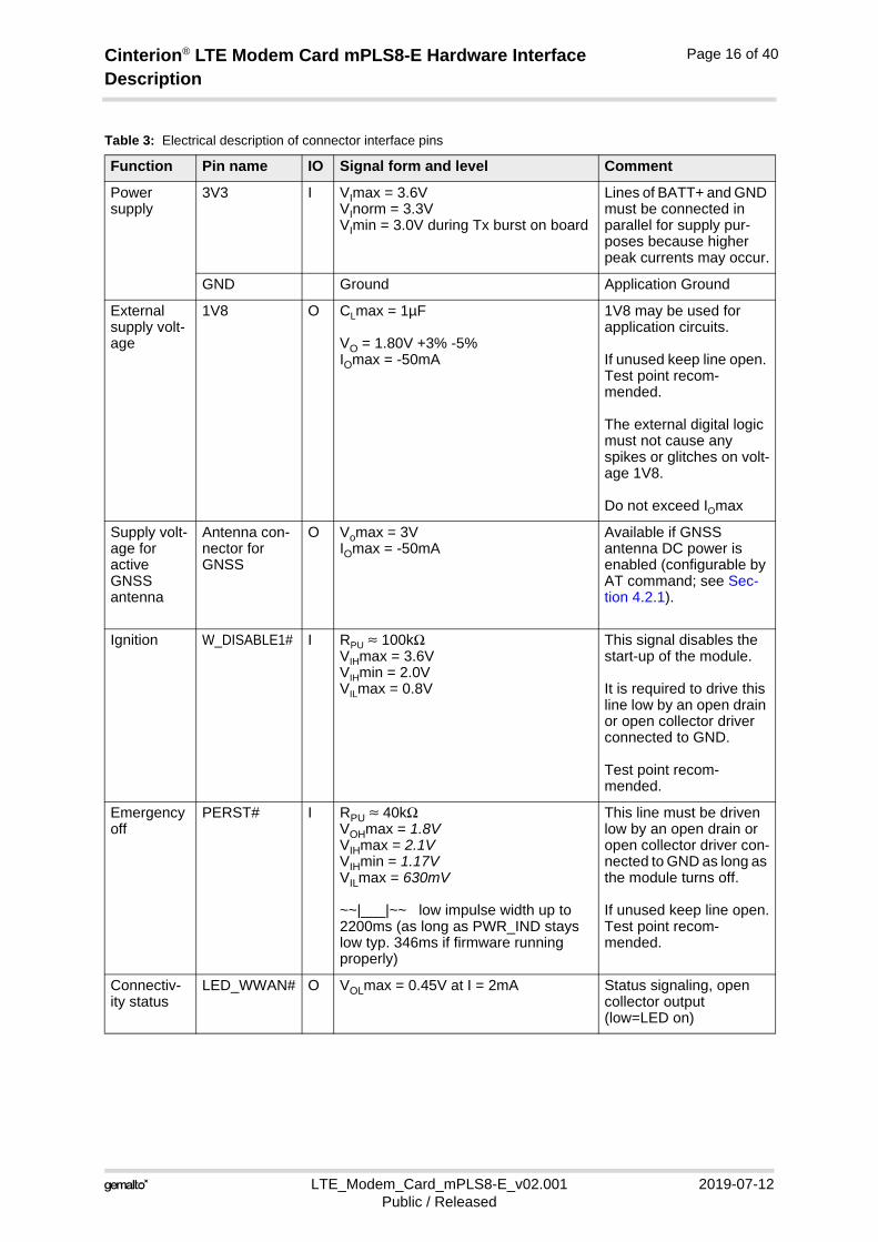
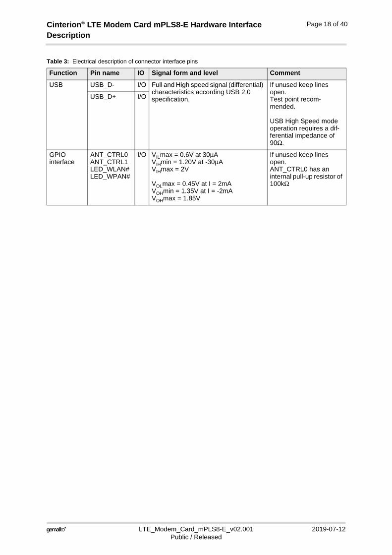
Table 3: Electrical description of connector interface pins
Function Pin name IO Signal form and level Comment
Power supply
3V3 I VImax = 3.6VVInorm = 3.3VVImin = 3.0V during Tx burst on board
Lines of BATT+ and GND must be connected in parallel for supply pur-poses because higher peak currents may occur.
GND Ground Application Ground
External supply volt-age
1V8 O CLmax = 1µF
VO = 1.80V +3% -5%IOmax = -50mA
1V8 may be used for application circuits.
If unused keep line open. Test point recom-mended.
The external digital logic must not cause any spikes or glitches on volt-age 1V8.
Do not exceed IOmax
Supply volt-age for active GNSS antenna
Antenna con-nector for GNSS
O Vomax = 3VIOmax = -50mA
Available if GNSS antenna DC power is enabled (configurable by AT command; see Sec-tion 4.2.1).
Ignition W_DISABLE1# I RPU ≈ 100kΩVIHmax = 3.6VVIHmin = 2.0VVILmax = 0.8V
This signal disables the start-up of the module.
It is required to drive this line low by an open drain or open collector driver connected to GND.
Test point recom-mended.
Emergency off
PERST# I RPU ≈ 40kΩ VOHmax = 1.8VVIHmax = 2.1V VIHmin = 1.17VVILmax = 630mV
~~|___|~~ low impulse width up to 2200ms (as long as PWR_IND stays low typ. 346ms if firmware running properly)
This line must be driven low by an open drain or open collector driver con-nected to GND as long as the module turns off.
If unused keep line open.Test point recom-mended.
Connectiv-ity status
LED_WWAN# O VOLmax = 0.45V at I = 2mA Status signaling, open collector output(low=LED on)
Cinterion® LTE Modem Card mPLS8-E Hardware Interface Description
LTE_Modem_Card_mPLS8-E_v02.001 2019-07-12Public / Released
Page 17 of 40
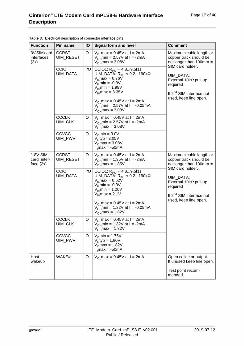
3V SIM card interfaces (2x)
CCRSTUIM_RESET
O VOLmax = 0.45V at I = 2mAVOHmin = 2.57V at I = -2mAVOHmax = 3.08V
Maximum cable length or copper track should be not longer than 100mm to SIM card holder.
UIM_DATA:External 10kΩ pull-up required
If 2nd SIM interface not used, keep line open.
CCIOUIM_DATA
I/O CCIO1: RPU ≈ 4.8...9.5kΩUIM_DATA: RPU ≈ 9.2...190kΩVILmax = 0.76VVILmin = -0.3VVIHmin = 1.98VVIHmax = 3.35V
VOLmax = 0.45V at I = 2mAVOHmin = 2.57V at I = -0.05mAVOHmax = 3.08V
CCCLKUIM_CLK
O VOLmax = 0.45V at I = 2mAVOHmin = 2.57V at I = -2mAVOHmax = 3.08V
CCVCCUIM_PWR
O VOmin = 3.0V VOtyp =3.05VVOmax = 3.08VIOmax = -50mA
1.8V SIM card inter-face (2x)
CCRSTUIM_RESET
O VOLmax = 0.45V at I = 2mAVOHmin = 1.35V at I = -2mAVOHmax = 1.85V
Maximum cable length or copper track should be not longer than 100mm to SIM card holder.
UIM_DATA:External 10kΩ pull-up required
If 2nd SIM interface not used, keep line open.
CCIOUIM_DATA
I/O CCIO1: RPU ≈ 4.8...9.5kΩUIM_DATA: RPU ≈ 9.2...190kΩVILmax = 0.62VVILmin = -0.3VVIHmin = 1.20VVIHmax = 2.1V
VOLmax = 0.45V at I = 2mAVOHmin = 1.32V at I = -0.05mAVOHmax = 1.82V
CCCLKUIM_CLK
O VOLmax = 0.45V at I = 2mAVOHmin = 1.32V at I = -2mAVOHmax = 1.82V
CCVCCUIM_PWR
O VOmin = 1.75V VOtyp = 1.80VVOmax = 1.82VIOmax = -50mA
Host wakeup
WAKE# O VOLmax = 0.45V at I = 2mA Open collector output.If unused keep line open.
Test point recom-mended.
Table 3: Electrical description of connector interface pins
Function Pin name IO Signal form and level Comment
Cinterion® LTE Modem Card mPLS8-E Hardware Interface Description
LTE_Modem_Card_mPLS8-E_v02.001 2019-07-12Public / Released
Page 18 of 40
USB USB_D- I/O Full and High speed signal (differential) characteristics according USB 2.0 specification.
If unused keep lines open.Test point recom-mended.
USB High Speed mode operation requires a dif-ferential impedance of 90Ω.
USB_D+ I/O
GPIOinterface
ANT_CTRL0ANT_CTRL1LED_WLAN#LED_WPAN#
I/O VILmax = 0.6V at 30µAVIHmin = 1.20V at -30µAVIHmax = 2V
VOLmax = 0.45V at I = 2mAVOHmin = 1.35V at I = -2mAVOHmax = 1.85V
If unused keep lines open.ANT_CTRL0 has an internal pull-up resistor of 100kΩ
Table 3: Electrical description of connector interface pins
Function Pin name IO Signal form and level Comment
Cinterion® LTE Modem Card mPLS8-E Hardware Interface Description
LTE_Modem_Card_mPLS8-E_v02.001 2019-07-12Public / Released
Page 19 of 40
3.2 Characteristics
3.2.1 Power Supply and Ground
The LTE Modem Card mPLS8-E uses the five 3V3 pins and 14 GND pins listed in Section 3.1.
3.2.2 USB Interface
The LTE Modem Card mPLS8-E‘s USB interface (USB_D+, USB_D-) as part of the 52-pin ap-plication connector supports a USB 2.0 High Speed (480Mbit/s) device interface that is Full Speed (12Mbit/s) compliant. Because there is no separate voltage detection line available on the application connector, the LTE Modem Card mPLS8-E reports as a self-powered device compliant with the “Universal Serial Bus Specification Revision 2.0”1.
Via the USB interface it is possible to implement a Gemalto M2M USB modem as well as six further Gemalto M2M ports that provide an AT interface to the module. The appropriate modem and port configuration files (INF) can be downloaded from the Gemalto M2M Extranet.
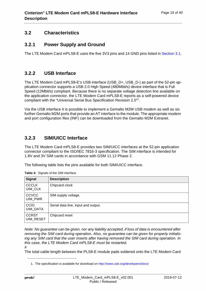
3.2.3 SIM/UICC Interface
The LTE Modem Card mPLS8-E provides two SIM/UICC interfaces at the 52-pin application connector compliant to the ISO/IEC 7816-3 specification. The SIM interface is intended for 1.8V and 3V SIM cards in accordance with GSM 11.12 Phase 2.
The following table lists the pins available for both SIM/UICC interface.
Note: No guarantee can be given, nor any liability accepted, if loss of data is encountered after removing the SIM card during operation. Also, no guarantee can be given for properly initializ-ing any SIM card that the user inserts after having removed the SIM card during operation. In this case, the LTE Modem Card mPLS8-E must be restarted.#The total cable length between the PLS8-E module pads soldered onto the LTE Modem Card
1. The specification is available for download on http://www.usb.org/developers/docs/
Table 4: Signals of the SIM interface
Signal Description
CCCLKUIM_CLK
Chipcard clock
CCVCCUIM_PWR
SIM supply voltage.
CCIOUIM_DATA
Serial data line, input and output.
CCRSTUIM_RESET
Chipcard reset
Cinterion® LTE Modem Card mPLS8-E Hardware Interface Description
LTE_Modem_Card_mPLS8-E_v02.001 2019-07-12Public / Released
Page 20 of 40
mPLS8-E and the pads of an external SIM card holder must not exceed 100mm in order to meet the specifications of 3GPP TS 51.010-1 and to satisfy the requirements of EMC compli-ance.
To avoid possible cross-talk from the CCCLK/UIM_CLK signal to the CCIO/UIM_DATA signal, be careful that both lines are not placed closely next to each other. A useful approach is using a GND line to shield the CCIO/UIM_DATA line from the CCCLK/UIM_CLK line.
LTE Modem Card mPLS8-E provides a micro-SIM (3FF) card holder soldered directly onto the LTE Modem Card. It is possible to insert a micro-SIM card (3FF) into the holder on the LTE Modem Card mPLS8-E. There is no need for a card holder in an external application. Simulta-neous operation of an external and the onboard SIM/UICC is not possible.
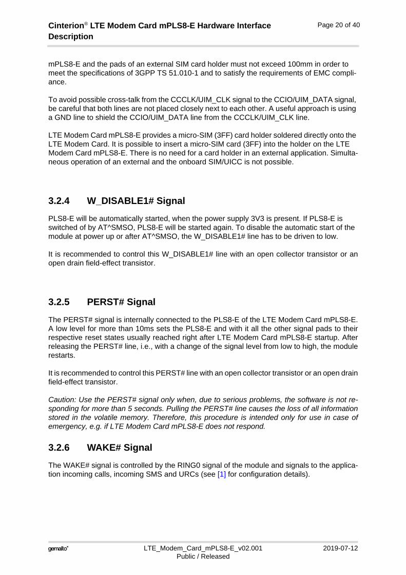
3.2.4 W_DISABLE1# Signal
PLS8-E will be automatically started, when the power supply 3V3 is present. If PLS8-E is switched of by AT^SMSO, PLS8-E will be started again. To disable the automatic start of the module at power up or after AT^SMSO, the W_DISABLE1# line has to be driven to low.
It is recommended to control this W_DISABLE1# line with an open collector transistor or anopen drain field-effect transistor.
3.2.5 PERST# Signal
The PERST# signal is internally connected to the PLS8-E of the LTE Modem Card mPLS8-E.A low level for more than 10ms sets the PLS8-E and with it all the other signal pads to theirrespective reset states usually reached right after LTE Modem Card mPLS8-E startup. Afterreleasing the PERST# line, i.e., with a change of the signal level from low to high, the modulerestarts.
It is recommended to control this PERST# line with an open collector transistor or an open drainfield-effect transistor.
Caution: Use the PERST# signal only when, due to serious problems, the software is not re-sponding for more than 5 seconds. Pulling the PERST# line causes the loss of all informationstored in the volatile memory. Therefore, this procedure is intended only for use in case ofemergency, e.g. if LTE Modem Card mPLS8-E does not respond.
3.2.6 WAKE# Signal
The WAKE# signal is controlled by the RING0 signal of the module and signals to the applica-tion incoming calls, incoming SMS and URCs (see [1] for configuration details).
Cinterion® LTE Modem Card mPLS8-E Hardware Interface Description
LTE_Modem_Card_mPLS8-E_v02.001 2019-07-12Public / Released
Page 21 of 40
4 Antenna Interface
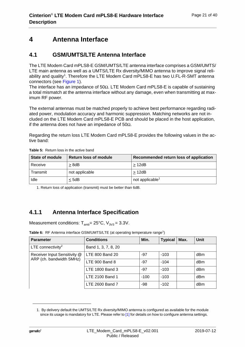
4.1 GSM/UMTS/LTE Antenna Interface
The LTE Modem Card mPLS8-E GSM/UMTS/LTE antenna interface comprises a GSM/UMTS/LTE main antenna as well as a UMTS/LTE Rx diversity/MIMO antenna to improve signal reli-ability and quality1. Therefore the LTE Modem Card mPLS8-E has two U.FL-R-SMT antenna connectors (see Figure 1). The interface has an impedance of 50Ω. LTE Modem Card mPLS8-E is capable of sustaining a total mismatch at the antenna interface without any damage, even when transmitting at max-imum RF power.
The external antennas must be matched properly to achieve best performance regarding radi-ated power, modulation accuracy and harmonic suppression. Matching networks are not in-cluded on the LTE Modem Card mPLS8-E PCB and should be placed in the host application, if the antenna does not have an impedance of 50Ω.
Regarding the return loss LTE Modem Card mPLS8-E provides the following values in the ac-tive band:
4.1.1 Antenna Interface Specification
Measurement conditions: Tamb= 25°C, V3V3 = 3.3V.
1. By delivery default the UMTS/LTE Rx diversity/MIMO antenna is configured as available for the modulesince its usage is mandatory for LTE. Please refer to [1] for details on how to configure antenna settings.
Table 5: Return loss in the active band
State of module Return loss of module Recommended return loss of application
Receive > 8dB > 12dB
Transmit not applicable > 12dB
Idle < 5dB not applicable1
1. Return loss of application (transmit) must be better than 6dB.
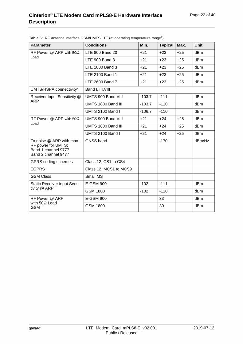
Table 6: RF Antenna interface GSM/UMTS/LTE (at operating temperature range1)
Parameter Conditions Min. Typical Max. Unit
LTE connectivity2 Band 1, 3, 7, 8, 20
Receiver Input Sensitivity @ ARP (ch. bandwidth 5MHz)
LTE 800 Band 20 -97 -103 dBm
LTE 900 Band 8 -97 -104 dBm
LTE 1800 Band 3 -97 -103 dBm
LTE 2100 Band 1 -100 -103 dBm
LTE 2600 Band 7 -98 -102 dBm
Cinterion® LTE Modem Card mPLS8-E Hardware Interface Description
LTE_Modem_Card_mPLS8-E_v02.001 2019-07-12Public / Released
Page 22 of 40
RF Power @ ARP with 50Ω Load
LTE 800 Band 20 +21 +23 +25 dBm
LTE 900 Band 8 +21 +23 +25 dBm
LTE 1800 Band 3 +21 +23 +25 dBm
LTE 2100 Band 1 +21 +23 +25 dBm
LTE 2600 Band 7 +21 +23 +25 dBm
UMTS/HSPA connectivity2 Band I, III,VIII
Receiver Input Sensitivity @ ARP
UMTS 900 Band VIII -103.7 -111 dBm
UMTS 1800 Band III -103.7 -110 dBm
UMTS 2100 Band I -106.7 -110 dBm
RF Power @ ARP with 50Ω Load
UMTS 900 Band VIII +21 +24 +25 dBm
UMTS 1800 Band III +21 +24 +25 dBm
UMTS 2100 Band I +21 +24 +25 dBm
Tx noise @ ARP with max. RF power for UMTS:Band 1 channel 9777Band 2 channel 9477
GNSS band -170 dBm/Hz
GPRS coding schemes Class 12, CS1 to CS4
EGPRS Class 12, MCS1 to MCS9
GSM Class Small MS
Static Receiver input Sensi-tivity @ ARP
E-GSM 900 -102 -111 dBm
GSM 1800 -102 -110 dBm
RF Power @ ARP with 50Ω Load GSM
E-GSM 900 33 dBm
GSM 1800 30 dBm
Table 6: RF Antenna interface GSM/UMTS/LTE (at operating temperature range1)
Parameter Conditions Min. Typical Max. Unit
Cinterion® LTE Modem Card mPLS8-E Hardware Interface Description
LTE_Modem_Card_mPLS8-E_v02.001 2019-07-12Public / Released
Page 23 of 40
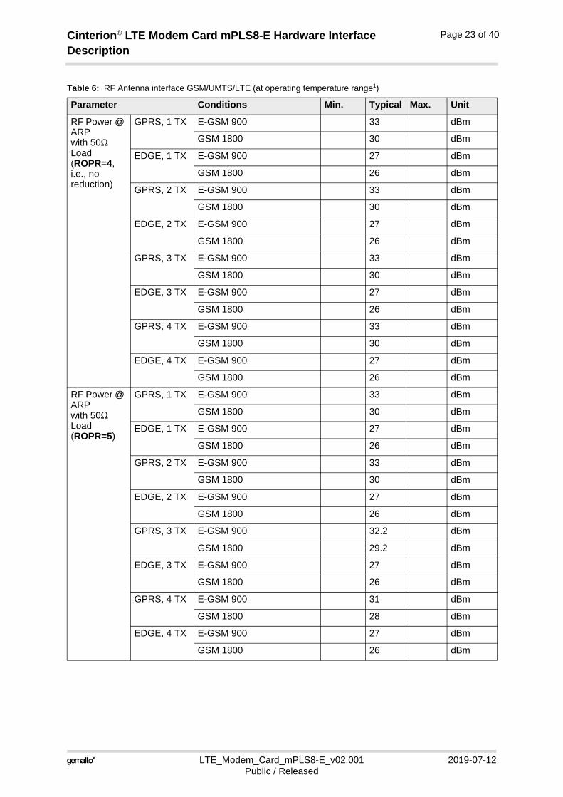
RF Power @ ARP with 50Ω Load(ROPR=4, i.e., no reduction)
GPRS, 1 TX E-GSM 900 33 dBm
GSM 1800 30 dBm
EDGE, 1 TX E-GSM 900 27 dBm
GSM 1800 26 dBm
GPRS, 2 TX E-GSM 900 33 dBm
GSM 1800 30 dBm
EDGE, 2 TX E-GSM 900 27 dBm
GSM 1800 26 dBm
GPRS, 3 TX E-GSM 900 33 dBm
GSM 1800 30 dBm
EDGE, 3 TX E-GSM 900 27 dBm
GSM 1800 26 dBm
GPRS, 4 TX E-GSM 900 33 dBm
GSM 1800 30 dBm
EDGE, 4 TX E-GSM 900 27 dBm
GSM 1800 26 dBm
RF Power @ ARP with 50Ω Load(ROPR=5)
GPRS, 1 TX E-GSM 900 33 dBm
GSM 1800 30 dBm
EDGE, 1 TX E-GSM 900 27 dBm
GSM 1800 26 dBm
GPRS, 2 TX E-GSM 900 33 dBm
GSM 1800 30 dBm
EDGE, 2 TX E-GSM 900 27 dBm
GSM 1800 26 dBm
GPRS, 3 TX E-GSM 900 32.2 dBm
GSM 1800 29.2 dBm
EDGE, 3 TX E-GSM 900 27 dBm
GSM 1800 26 dBm
GPRS, 4 TX E-GSM 900 31 dBm
GSM 1800 28 dBm
EDGE, 4 TX E-GSM 900 27 dBm
GSM 1800 26 dBm
Table 6: RF Antenna interface GSM/UMTS/LTE (at operating temperature range1)
Parameter Conditions Min. Typical Max. Unit
Cinterion® LTE Modem Card mPLS8-E Hardware Interface Description
LTE_Modem_Card_mPLS8-E_v02.001 2019-07-12Public / Released
Page 24 of 40
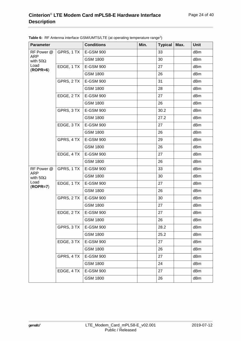
RF Power @ ARP with 50Ω Load(ROPR=6)
GPRS, 1 TX E-GSM 900 33 dBm
GSM 1800 30 dBm
EDGE, 1 TX E-GSM 900 27 dBm
GSM 1800 26 dBm
GPRS, 2 TX E-GSM 900 31 dBm
GSM 1800 28 dBm
EDGE, 2 TX E-GSM 900 27 dBm
GSM 1800 26 dBm
GPRS, 3 TX E-GSM 900 30.2 dBm
GSM 1800 27.2 dBm
EDGE, 3 TX E-GSM 900 27 dBm
GSM 1800 26 dBm
GPRS, 4 TX E-GSM 900 29 dBm
GSM 1800 26 dBm
EDGE, 4 TX E-GSM 900 27 dBm
GSM 1800 26 dBm
RF Power @ ARP with 50Ω Load(ROPR=7)
GPRS, 1 TX E-GSM 900 33 dBm
GSM 1800 30 dBm
EDGE, 1 TX E-GSM 900 27 dBm
GSM 1800 26 dBm
GPRS, 2 TX E-GSM 900 30 dBm
GSM 1800 27 dBm
EDGE, 2 TX E-GSM 900 27 dBm
GSM 1800 26 dBm
GPRS, 3 TX E-GSM 900 28.2 dBm
GSM 1800 25.2 dBm
EDGE, 3 TX E-GSM 900 27 dBm
GSM 1800 26 dBm
GPRS, 4 TX E-GSM 900 27 dBm
GSM 1800 24 dBm
EDGE, 4 TX E-GSM 900 27 dBm
GSM 1800 26 dBm
Table 6: RF Antenna interface GSM/UMTS/LTE (at operating temperature range1)
Parameter Conditions Min. Typical Max. Unit
Cinterion® LTE Modem Card mPLS8-E Hardware Interface Description
LTE_Modem_Card_mPLS8-E_v02.001 2019-07-12Public / Released
Page 25 of 40
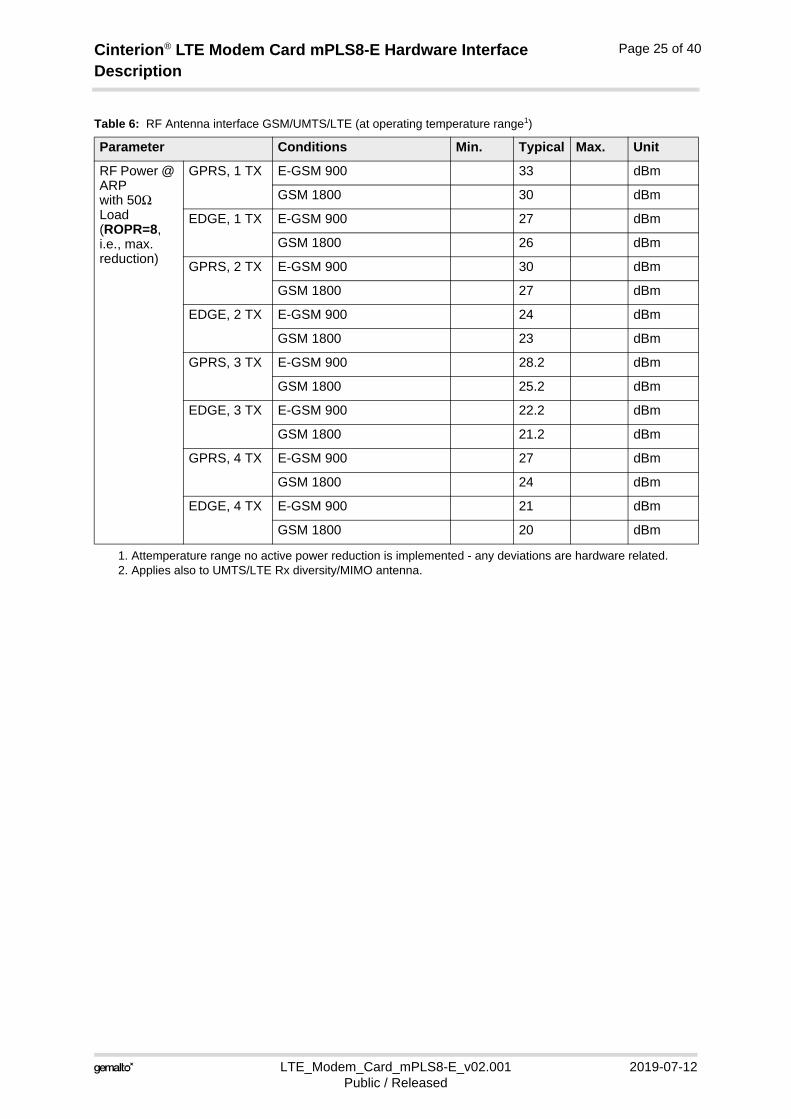
RF Power @ ARP with 50Ω Load(ROPR=8, i.e., max. reduction)
GPRS, 1 TX E-GSM 900 33 dBm
GSM 1800 30 dBm
EDGE, 1 TX E-GSM 900 27 dBm
GSM 1800 26 dBm
GPRS, 2 TX E-GSM 900 30 dBm
GSM 1800 27 dBm
EDGE, 2 TX E-GSM 900 24 dBm
GSM 1800 23 dBm
GPRS, 3 TX E-GSM 900 28.2 dBm
GSM 1800 25.2 dBm
EDGE, 3 TX E-GSM 900 22.2 dBm
GSM 1800 21.2 dBm
GPRS, 4 TX E-GSM 900 27 dBm
GSM 1800 24 dBm
EDGE, 4 TX E-GSM 900 21 dBm
GSM 1800 20 dBm
1. Attemperature range no active power reduction is implemented - any deviations are hardware related.2. Applies also to UMTS/LTE Rx diversity/MIMO antenna.
Table 6: RF Antenna interface GSM/UMTS/LTE (at operating temperature range1)
Parameter Conditions Min. Typical Max. Unit
Cinterion® LTE Modem Card mPLS8-E Hardware Interface Description
LTE_Modem_Card_mPLS8-E_v02.001 2019-07-12Public / Released
Page 26 of 40
4.2 GNSS Antenna Interface
In addition to the RF antenna interface LTE Modem Card mPLS8-E also has a GNSS antenna interface. See Figure 1 to find out where the GNSS antenna pad is located.
It is possible to connect active or passive GNSS antennas. In either case they must have 50Ω impedance. The simultaneous operation of GSM/UMTS/LTE and GNSS is implemented. For electrical characteristics see Section 4.2.1.
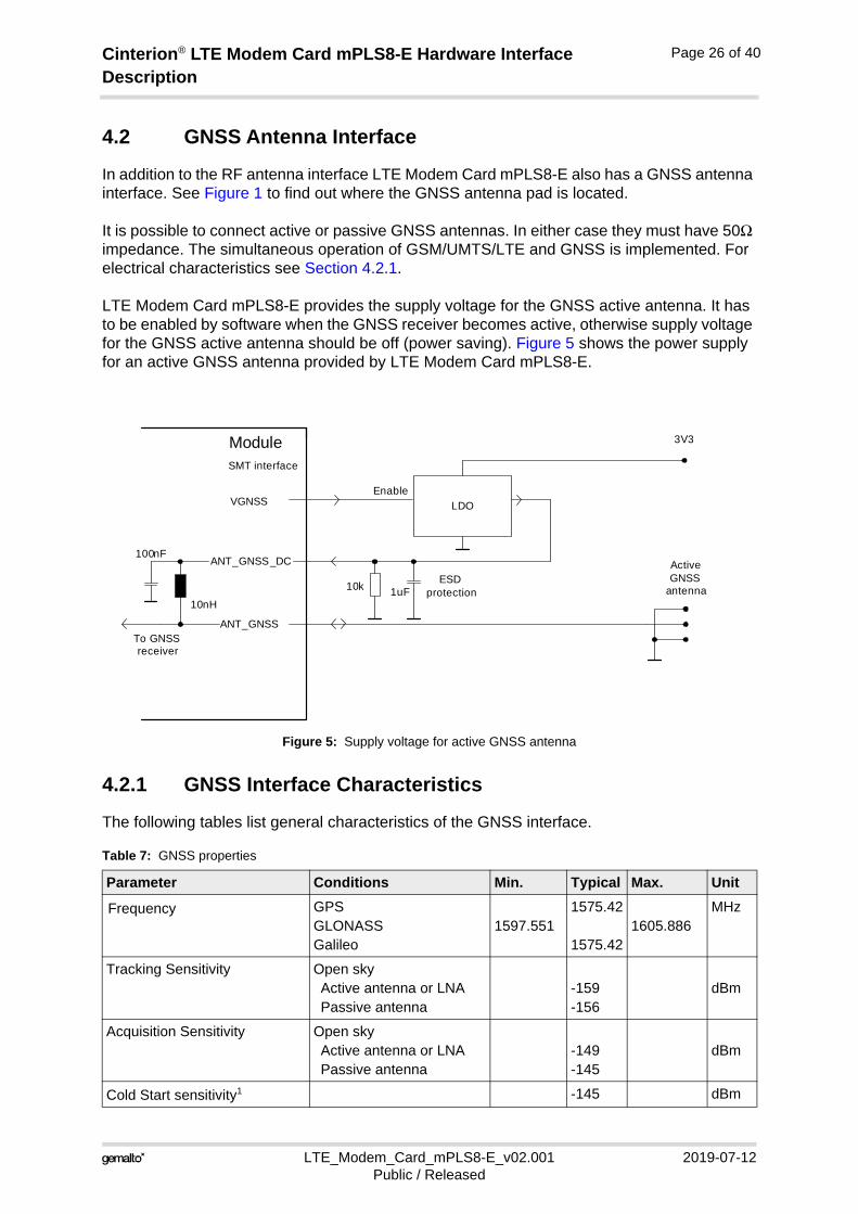
LTE Modem Card mPLS8-E provides the supply voltage for the GNSS active antenna. It has to be enabled by software when the GNSS receiver becomes active, otherwise supply voltage for the GNSS active antenna should be off (power saving). Figure 5 shows the power supply for an active GNSS antenna provided by LTE Modem Card mPLS8-E.
Figure 5: Supply voltage for active GNSS antenna
4.2.1 GNSS Interface Characteristics
The following tables list general characteristics of the GNSS interface.
Table 7: GNSS properties
Parameter Conditions Min. Typical Max. Unit
Frequency GPSGLONASSGalileo
1597.5511575.42
1575.421605.886
MHz
Tracking Sensitivity Open skyActive antenna or LNAPassive antenna
-159 -156
dBm
Acquisition Sensitivity Open skyActive antenna or LNAPassive antenna
-149-145
dBm
Cold Start sensitivity1 -145 dBm
LDOVGNSS
ANT_GNSS
Active GNSS
antenna10nH
100nF
To GNSS receiver
ModuleSMT interface
ANT_GNSS_DC
1uFESD
protection10k
Enable
3V3
Cinterion® LTE Modem Card mPLS8-E Hardware Interface Description
LTE_Modem_Card_mPLS8-E_v02.001 2019-07-12Public / Released
Page 27 of 40
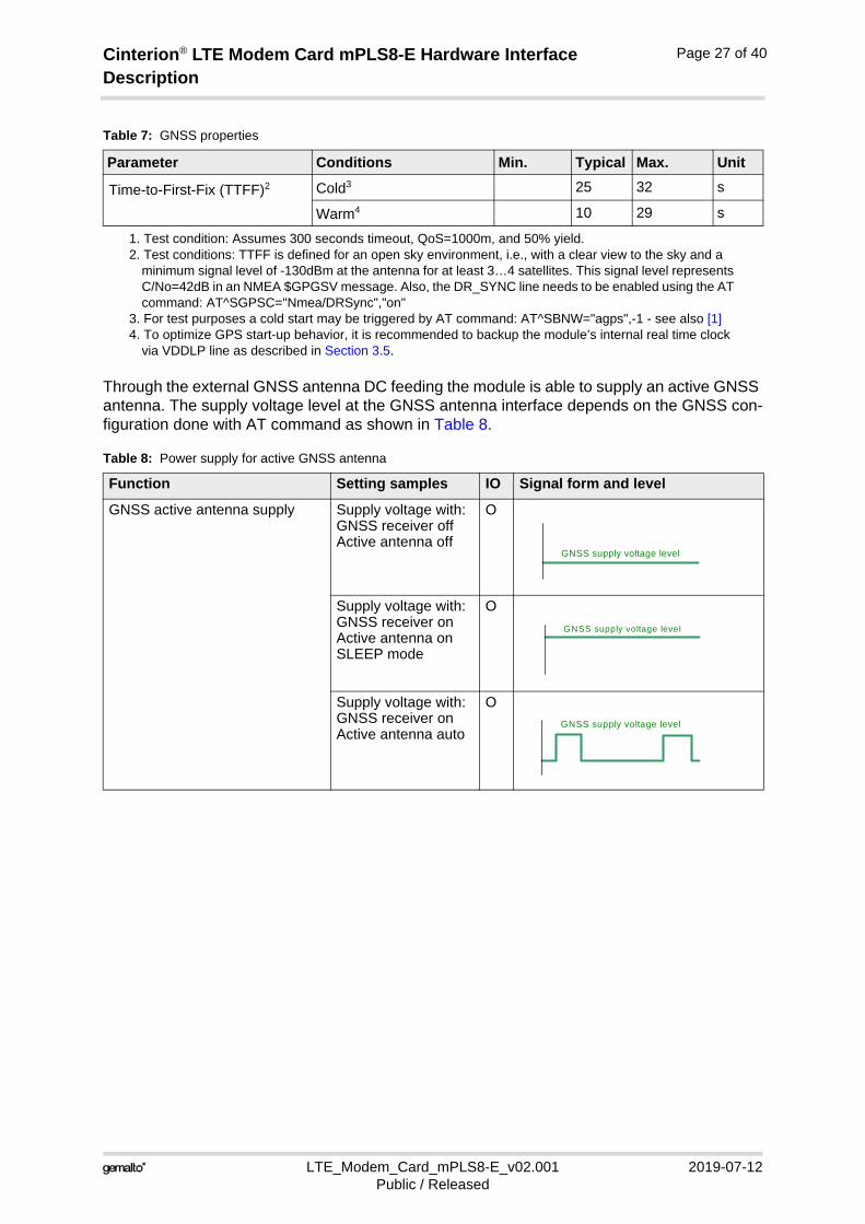
Through the external GNSS antenna DC feeding the module is able to supply an active GNSS antenna. The supply voltage level at the GNSS antenna interface depends on the GNSS con-figuration done with AT command as shown in Table 8.
Time-to-First-Fix (TTFF)2 Cold3 25 32 s
Warm4 10 29 s
1. Test condition: Assumes 300 seconds timeout, QoS=1000m, and 50% yield.2. Test conditions: TTFF is defined for an open sky environment, i.e., with a clear view to the sky and a
minimum signal level of -130dBm at the antenna for at least 3…4 satellites. This signal level represents C/No=42dB in an NMEA $GPGSV message. Also, the DR_SYNC line needs to be enabled using the AT command: AT^SGPSC="Nmea/DRSync","on"
3. For test purposes a cold start may be triggered by AT command: AT^SBNW="agps",-1 - see also [1]4. To optimize GPS start-up behavior, it is recommended to backup the module’s internal real time clock
via VDDLP line as described in Section 3.5.
Table 8: Power supply for active GNSS antenna
Function Setting samples IO Signal form and level
GNSS active antenna supply Supply voltage with:GNSS receiver offActive antenna off
O
Supply voltage with: GNSS receiver onActive antenna onSLEEP mode
O
Supply voltage with: GNSS receiver onActive antenna auto
O
Table 7: GNSS properties
Parameter Conditions Min. Typical Max. Unit
GNSS supply voltage level
GNSS supply voltage level
GNSS supply voltage level
Cinterion® LTE Modem Card mPLS8-E Hardware Interface Description
LTE_Modem_Card_mPLS8-E_v02.001 2019-07-12Public / Released
Page 28 of 40
4.3 GNSS Interface Characteristics
The following tables list general characteristics of the GNSS interface.
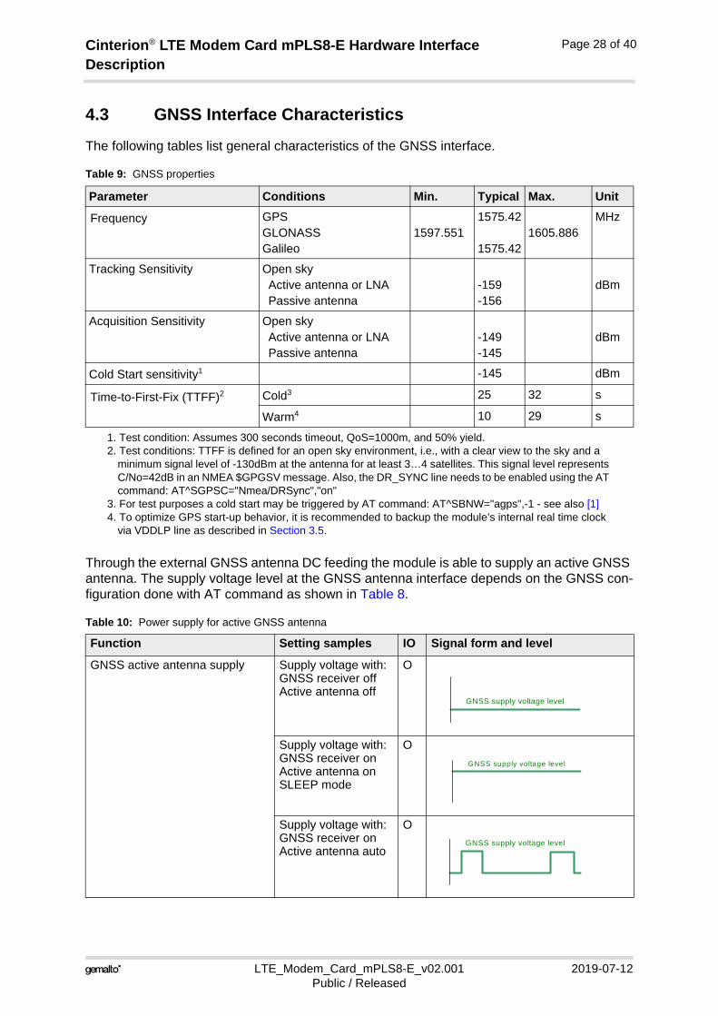
Through the external GNSS antenna DC feeding the module is able to supply an active GNSS antenna. The supply voltage level at the GNSS antenna interface depends on the GNSS con-figuration done with AT command as shown in Table 8.
Table 9: GNSS properties
Parameter Conditions Min. Typical Max. Unit
Frequency GPSGLONASSGalileo
1597.5511575.42
1575.421605.886
MHz
Tracking Sensitivity Open skyActive antenna or LNAPassive antenna
-159 -156
dBm
Acquisition Sensitivity Open skyActive antenna or LNAPassive antenna
-149-145
dBm
Cold Start sensitivity1
1. Test condition: Assumes 300 seconds timeout, QoS=1000m, and 50% yield.
-145 dBm
Time-to-First-Fix (TTFF)2
2. Test conditions: TTFF is defined for an open sky environment, i.e., with a clear view to the sky and a minimum signal level of -130dBm at the antenna for at least 3…4 satellites. This signal level represents C/No=42dB in an NMEA $GPGSV message. Also, the DR_SYNC line needs to be enabled using the AT command: AT^SGPSC="Nmea/DRSync","on"
Cold3
3. For test purposes a cold start may be triggered by AT command: AT^SBNW="agps",-1 - see also [1]
25 32 s
Warm4
4. To optimize GPS start-up behavior, it is recommended to backup the module’s internal real time clock via VDDLP line as described in Section 3.5.
10 29 s
Table 10: Power supply for active GNSS antenna
Function Setting samples IO Signal form and level
GNSS active antenna supply Supply voltage with:GNSS receiver offActive antenna off
O
Supply voltage with: GNSS receiver onActive antenna onSLEEP mode
O
Supply voltage with: GNSS receiver onActive antenna auto
O
GNSS supply voltage level
GNSS supply voltage level
GNSS supply voltage level
Cinterion® LTE Modem Card mPLS8-E Hardware Interface Description
LTE_Modem_Card_mPLS8-E_v02.001 2019-07-12Public / Released
Page 29 of 40
5 Operation
5.1 Operating Modes
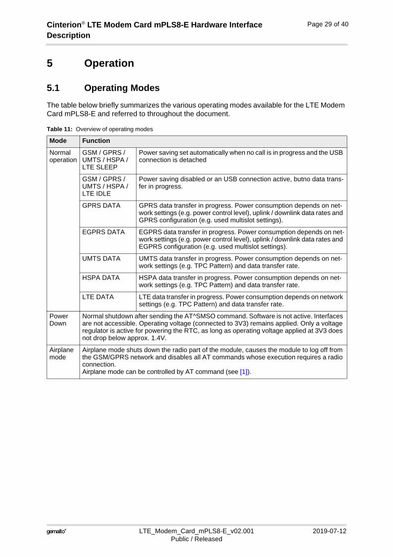
The table below briefly summarizes the various operating modes available for the LTE Modem Card mPLS8-E and referred to throughout the document.
Table 11: Overview of operating modes
Mode Function
Normal operation
GSM / GPRS / UMTS / HSPA /LTE SLEEP
Power saving set automatically when no call is in progress and the USB connection is detached
GSM / GPRS / UMTS / HSPA / LTE IDLE
Power saving disabled or an USB connection active, butno data trans-fer in progress.
GPRS DATA GPRS data transfer in progress. Power consumption depends on net-work settings (e.g. power control level), uplink / downlink data rates and GPRS configuration (e.g. used multislot settings).
EGPRS DATA EGPRS data transfer in progress. Power consumption depends on net-work settings (e.g. power control level), uplink / downlink data rates and EGPRS configuration (e.g. used multislot settings).
UMTS DATA UMTS data transfer in progress. Power consumption depends on net-work settings (e.g. TPC Pattern) and data transfer rate.
HSPA DATA HSPA data transfer in progress. Power consumption depends on net-work settings (e.g. TPC Pattern) and data transfer rate.
LTE DATA LTE data transfer in progress. Power consumption depends on network settings (e.g. TPC Pattern) and data transfer rate.
Power Down
Normal shutdown after sending the AT^SMSO command. Software is not active. Interfaces are not accessible. Operating voltage (connected to 3V3) remains applied. Only a voltage regulator is active for powering the RTC, as long as operating voltage applied at 3V3 does not drop below approx. 1.4V.
Airplane mode
Airplane mode shuts down the radio part of the module, causes the module to log off from the GSM/GPRS network and disables all AT commands whose execution requires a radio connection.Airplane mode can be controlled by AT command (see [1]).
Cinterion® LTE Modem Card mPLS8-E Hardware Interface Description
LTE_Modem_Card_mPLS8-E_v02.001 2019-07-12Public / Released
Page 30 of 40
5.2 Power Up/Power Down Scenarios
In general, be sure not to turn on the LTE Modem Card mPLS8-E while it is beyond the safety limits of voltage and temperature stated in Section 5.4 and Section 5.5.LTE Modem Card mPLS8-E will switch off after having detected these inappropriate conditions. In extreme cases this can cause permanent damage to the LTE Modem Card mPLS8-E.
5.2.1 Turn LTE Modem Card mPLS8-E on
The LTE Modem Card mPLS8-E is turned on by connecting the power supply lines (3V3) of application connector to an external power supply source, e.g., by plugging the LTE Modem Card mPLS8-E into the appropriate card slot of an external application. For electrical charac-teristics of the 3V3 lines see Section 3.2.1. W_DISABLE1# signal goes high when LTE modem card is powered.
A dual inverter schmitt trigger & OC transistor circuitry will keep IGT signal of PLS8-E low for the required minimum time of 100ms to startup the LTE modem card.
The automatic start-up can be disabled by the signal W_DISABLE1# driving low.
5.2.2 Reset/Restart LTE Modem Card mPLS8-E
The LTE Modem Card mPLS8-E can be reseted by driving the PERST# line of the application connector low for more than 10ms. For more information on the PERST# line see Section 3.2.5.
5.2.3 Turn LTE Modem Card mPLS8-E off
The LTE Modem Card mPLS8-E can be turned off by disconnecting the power supply lines (3V3), e.g., by unplugging the LTE Modem Card from its socket.
The LTE Modem Card mPLS8-E can be switched of by AT^SMSO too, but to prevent automatic start-up again, the signal W_DISBALE1# has to be driven LOW.
Note: Before disconnecting the power supply lines, make sure that the LTE Modem Card mPLS8-E is in a safe condition, i.e., that there are no data transfers or other communications going on. Volatile data may be lost.
Cinterion® LTE Modem Card mPLS8-E Hardware Interface Description
LTE_Modem_Card_mPLS8-E_v02.001 2019-07-12Public / Released
Page 31 of 40
5.3 Automatic thermal shutdown
An on-board NTC measures the temperature of the built-in module. If over- or undertempera-ture is detected on the module, LTE Modem Card mPLS8-E automatically shuts down to avoid thermal damage to the system. Table 12 specifies the ambient temperature threshold for the LTE Modem Card mPLS8-E.
On automatic shutdown procedure LTE Modem Card mPLS8-E logs off from the network and the software enters a secure state avoiding loss of data.
Note: The LTE Modem Card mPLS8-E will start immediately after thermal shutdown as long as the W_DISABLE#_1 is not driven low.
Alert messages transmitted before the LTE Modem Card mPLS8-E switch off are implemented as Unsolicited Result codes (URCs). For details see the description of AT^SCTM command provided in [1].
Cinterion® LTE Modem Card mPLS8-E Hardware Interface Description
LTE_Modem_Card_mPLS8-E_v02.001 2019-07-12Public / Released
Page 32 of 40
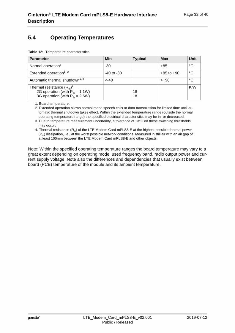
5.4 Operating Temperatures
Note: Within the specified operating temperature ranges the board temperature may vary to a great extent depending on operating mode, used frequency band, radio output power and cur-rent supply voltage. Note also the differences and dependencies that usually exist between board (PCB) temperature of the module and its ambient temperature.
Table 12: Temperature characteristics
Parameter Min Typical Max Unit
Normal operation1
1. Board temperature.
-30 +85 °C
Extended operation1, 2
2. Extended operation allows normal mode speech calls or data transmission for limited time until au-tomatic thermal shutdown takes effect. Within the extended temperature range (outside the normal operating temperature range) the specified electrical characteristics may be in- or decreased.
-40 to -30 +85 to +90 °C
Automatic thermal shutdown1, 3
3. Due to temperature measurement uncertainty, a tolerance of ±3°C on these switching thresholds may occur.
<-40 >+90 °C
Thermal resistance (Rth)4
2G operation (with Pth = 1.1W)3G operation (with Pth = 2.6W)
4. Thermal resistance (Rth) of the LTE Modem Card mPLS8-E at the highest possible thermal power (Pth) dissipation, i.e., at the worst possible network conditions. Measured in still air with an air gap of at least 100mm between the LTE Modem Card mPLS8-E and other objects.
1818
K/W
Cinterion® LTE Modem Card mPLS8-E Hardware Interface Description
LTE_Modem_Card_mPLS8-E_v02.001 2019-07-12Public / Released
Page 33 of 40
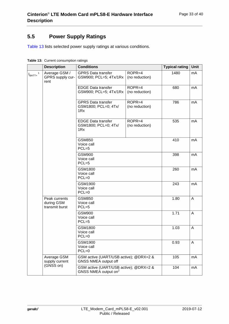
5.5 Power Supply Ratings
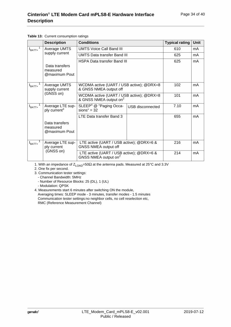
Table 13 lists selected power supply ratings at various conditions.
Table 13: Current consumption ratings
Description Conditions Typical rating Unit
IBATT+ 1 Average GSM /
GPRS supply cur-rent
GPRS Data transfer GSM900; PCL=5; 4Tx/1Rx
ROPR=4(no reduction)
1480 mA
EDGE Data transfer GSM900; PCL=5; 4Tx/1Rx
ROPR=4(no reduction)
680 mA
GPRS Data transfer GSM1800; PCL=0; 4Tx/1Rx
ROPR=4(no reduction)
786 mA
EDGE Data transfer GSM1800; PCL=0; 4Tx/1Rx
ROPR=4(no reduction)
535 mA
GSM850Voice callPCL=5
410 mA
GSM900Voice callPCL=5
398 mA
GSM1800Voice callPCL=0
260 mA
GSM1900Voice callPCL=0
243 mA
Peak currents during GSM transmit burst
GSM850Voice callPCL=5
1.80 A
GSM900Voice callPCL=5
1.71 A
GSM1800Voice callPCL=0
1.03 A
GSM1900Voice callPCL=0
0.93 A
Average GSM supply current (GNSS on)
GSM active (UART/USB active); @DRX=2 & GNSS NMEA output off
105 mA
GSM active (UART/USB active); @DRX=2 & GNSS NMEA output on2
104 mA
Cinterion® LTE Modem Card mPLS8-E Hardware Interface Description
LTE_Modem_Card_mPLS8-E_v02.001 2019-07-12Public / Released
Page 34 of 40
IBATT+ 1 Average UMTS
supply current
Data transfers measured @maximum Pout
UMTS Voice Call Band III 610 mA
UMTS Data transfer Band III 625 mA
HSPA Data transfer Band III 625 mA
IBATT+ 1 Average UMTS
supply current (GNSS on)
WCDMA active (UART / USB active); @DRX=8 & GNSS NMEA output off
102 mA
WCDMA active (UART / USB active); @DRX=8 & GNSS NMEA output on2
101 mA
IBATT+ 1 Average LTE sup-
ply current3
Data transfers measured @maximum Pout
SLEEP4 @ "Paging Occa-sions" = 32
USB disconnected 7.10 mA
LTE Data transfer Band 3 655 mA
IBATT+ 1 Average LTE sup-
ply current (GNSS on)
LTE active (UART / USB active); @DRX=6 & GNSS NMEA output off
216 mA
LTE active (UART / USB active); @DRX=6 & GNSS NMEA output on2
214 mA
1. With an impedance of ZLOAD=50Ω at the antenna pads. Measured at 25°C and 3.3V2. One fix per second.3. Communication tester settings:
- Channel Bandwidth: 5MHz - Number of Resource Blocks: 25 (DL), 1 (UL) - Modulation: QPSK
4. Measurements start 6 minutes after switching ON the module,Averaging times: SLEEP mode - 3 minutes, transfer modes - 1.5 minutesCommunication tester settings:no neighbor cells, no cell reselection etc,RMC (Reference Measurement Channel)
Table 13: Current consumption ratings
Description Conditions Typical rating Unit
Cinterion® LTE Modem Card mPLS8-E Hardware Interface Description
LTE_Modem_Card_mPLS8-E_v02.001 2019-07-12Public / Released
Page 35 of 40
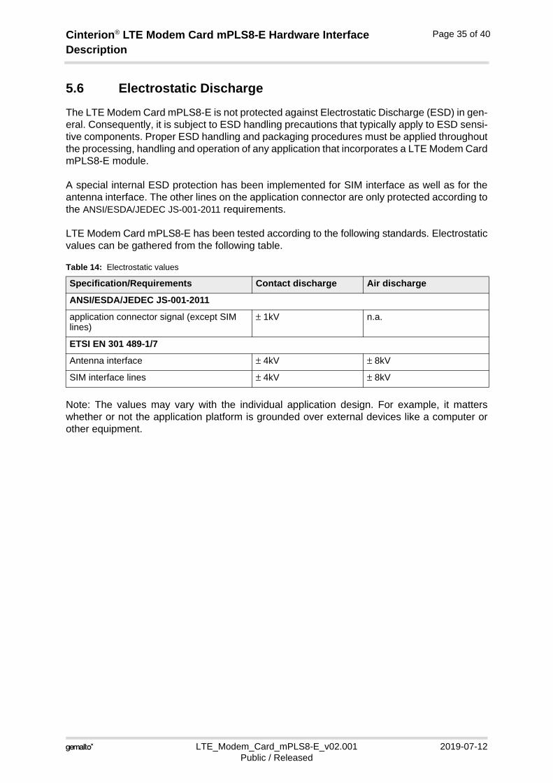
5.6 Electrostatic Discharge
The LTE Modem Card mPLS8-E is not protected against Electrostatic Discharge (ESD) in gen-eral. Consequently, it is subject to ESD handling precautions that typically apply to ESD sensi-tive components. Proper ESD handling and packaging procedures must be applied throughoutthe processing, handling and operation of any application that incorporates a LTE Modem CardmPLS8-E module.
A special internal ESD protection has been implemented for SIM interface as well as for theantenna interface. The other lines on the application connector are only protected according tothe ANSI/ESDA/JEDEC JS-001-2011 requirements.
LTE Modem Card mPLS8-E has been tested according to the following standards. Electrostaticvalues can be gathered from the following table.
Note: The values may vary with the individual application design. For example, it matterswhether or not the application platform is grounded over external devices like a computer orother equipment.
Table 14: Electrostatic values
Specification/Requirements Contact discharge Air discharge
ANSI/ESDA/JEDEC JS-001-2011
application connector signal (except SIM lines)
± 1kV n.a.
ETSI EN 301 489-1/7
Antenna interface ± 4kV ± 8kV
SIM interface lines ± 4kV ± 8kV
Cinterion® LTE Modem Card mPLS8-E Hardware Interface Description
LTE_Modem_Card_mPLS8-E_v02.001 2019-07-12Public / Released
Page 36 of 40
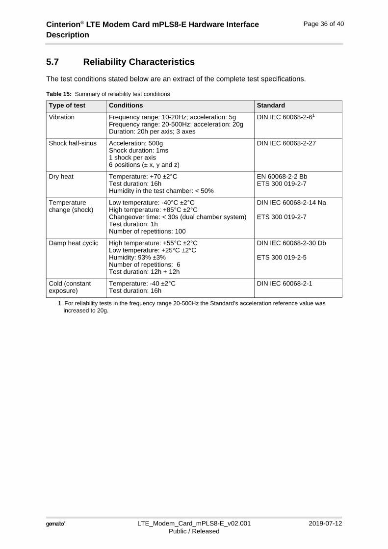
5.7 Reliability Characteristics
The test conditions stated below are an extract of the complete test specifications.
Table 15: Summary of reliability test conditions
Type of test Conditions Standard
Vibration Frequency range: 10-20Hz; acceleration: 5gFrequency range: 20-500Hz; acceleration: 20gDuration: 20h per axis; 3 axes
DIN IEC 60068-2-61
1. For reliability tests in the frequency range 20-500Hz the Standard’s acceleration reference value was increased to 20g.
Shock half-sinus Acceleration: 500gShock duration: 1ms1 shock per axis6 positions (± x, y and z)
DIN IEC 60068-2-27
Dry heat Temperature: +70 ±2°CTest duration: 16hHumidity in the test chamber: < 50%
EN 60068-2-2 Bb ETS 300 019-2-7
Temperature change (shock)
Low temperature: -40°C ±2°CHigh temperature: +85°C ±2°CChangeover time: < 30s (dual chamber system)Test duration: 1hNumber of repetitions: 100
DIN IEC 60068-2-14 Na
ETS 300 019-2-7
Damp heat cyclic High temperature: +55°C ±2°CLow temperature: +25°C ±2°CHumidity: 93% ±3%Number of repetitions: 6Test duration: 12h + 12h
DIN IEC 60068-2-30 Db
ETS 300 019-2-5
Cold (constant exposure)
Temperature: -40 ±2°CTest duration: 16h
DIN IEC 60068-2-1
Cinterion® LTE Modem Card mPLS8-E Hardware Interface Description
LTE_Modem_Card_mPLS8-E_v02.001 2019-07-12Public / Released
Page 37 of 40
5.8 Approval Information
The PLS8-E module as part of the LTE Modem Card mPLS8-E has been type approved. The Gemalto M2M reference setup submitted to type approve the module consisted of the following components: PLS8-E, PC as MMI, Power Supply.
Approval of mobile computing platforms containing LTE Modem Card mPLS8-E can therefore be based on the existing module approval together with this document as appropriate technical documentation.
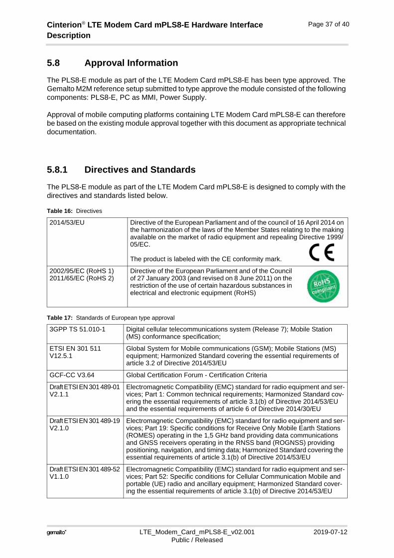
5.8.1 Directives and Standards
The PLS8-E module as part of the LTE Modem Card mPLS8-E is designed to comply with the directives and standards listed below.
Table 16: Directives
2014/53/EU Directive of the European Parliament and of the council of 16 April 2014 on the harmonization of the laws of the Member States relating to the making available on the market of radio equipment and repealing Directive 1999/ 05/EC.
The product is labeled with the CE conformity mark.
2002/95/EC (RoHS 1)2011/65/EC (RoHS 2)
Directive of the European Parliament and of the Council of 27 January 2003 (and revised on 8 June 2011) on the restriction of the use of certain hazardous substances in electrical and electronic equipment (RoHS)
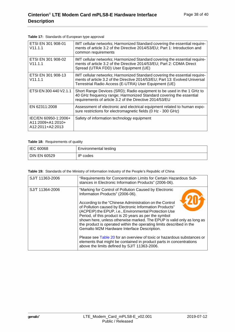
Table 17: Standards of European type approval
3GPP TS 51.010-1 Digital cellular telecommunications system (Release 7); Mobile Station (MS) conformance specification;
ETSI EN 301 511 V12.5.1
Global System for Mobile communications (GSM); Mobile Stations (MS) equipment; Harmonized Standard covering the essential requirements of article 3.2 of Directive 2014/53/EU
GCF-CC V3.64 Global Certification Forum - Certification Criteria
Draft ETSI EN 301 489-01 V2.1.1
Electromagnetic Compatibility (EMC) standard for radio equipment and ser-vices; Part 1: Common technical requirements; Harmonized Standard cov-ering the essential requirements of article 3.1(b) of Directive 2014/53/EU and the essential requirements of article 6 of Directive 2014/30/EU
Draft ETSI EN 301 489-19 V2.1.0
Electromagnetic Compatibility (EMC) standard for radio equipment and ser-vices; Part 19: Specific conditions for Receive Only Mobile Earth Stations (ROMES) operating in the 1,5 GHz band providing data communications and GNSS receivers operating in the RNSS band (ROGNSS) providing positioning, navigation, and timing data; Harmonized Standard covering the essential requirements of article 3.1(b) of Directive 2014/53/EU
Draft ETSI EN 301 489-52 V1.1.0
Electromagnetic Compatibility (EMC) standard for radio equipment and ser-vices; Part 52: Specific conditions for Cellular Communication Mobile and portable (UE) radio and ancillary equipment; Harmonized Standard cover-ing the essential requirements of article 3.1(b) of Directive 2014/53/EU
Cinterion® LTE Modem Card mPLS8-E Hardware Interface Description
LTE_Modem_Card_mPLS8-E_v02.001 2019-07-12Public / Released
Page 38 of 40
ETSI EN 301 908-01 V11.1.1
IMT cellular networks; Harmonized Standard covering the essential require-ments of article 3.2 of the Directive 2014/53/EU; Part 1: Introduction and common requirements
ETSI EN 301 908-02 V11.1.1
IMT cellular networks; Harmonized Standard covering the essential require-ments of article 3.2 of the Directive 2014/53/EU; Part 2: CDMA Direct Spread (UTRA FDD) User Equipment (UE)
ETSI EN 301 908-13 V11.1.1
IMT cellular networks; Harmonized Standard covering the essential require-ments of article 3.2 of the Directive 2014/53/EU; Part 13: Evolved Universal Terrestrial Radio Access (E-UTRA) User Equipment (UE)
ETSI EN 300 440 V2.1.1 Short Range Devices (SRD); Radio equipment to be used in the 1 GHz to 40 GHz frequency range; Harmonized Standard covering the essential requirements of article 3.2 of the Directive 2014/53/EU
EN 62311:2008 Assessment of electronic and electrical equipment related to human expo-sure restrictions for electromagnetic fields (0 Hz - 300 GHz)
IEC/EN 60950-1:2006+A11:2009+A1:2010+A12:2011+A2:2013
Safety of information technology equipment
Table 18: Requirements of quality
IEC 60068 Environmental testing
DIN EN 60529 IP codes
Table 19: Standards of the Ministry of Information Industry of the People’s Republic of China
SJ/T 11363-2006 “Requirements for Concentration Limits for Certain Hazardous Sub-stances in Electronic Information Products” (2006-06).
SJ/T 11364-2006 “Marking for Control of Pollution Caused by Electronic Information Products” (2006-06).
According to the “Chinese Administration on the Control of Pollution caused by Electronic Information Products” (ACPEIP) the EPUP, i.e., Environmental Protection Use Period, of this product is 20 years as per the symbol shown here, unless otherwise marked. The EPUP is valid only as long as the product is operated within the operating limits described in the Gemalto M2M Hardware Interface Description.
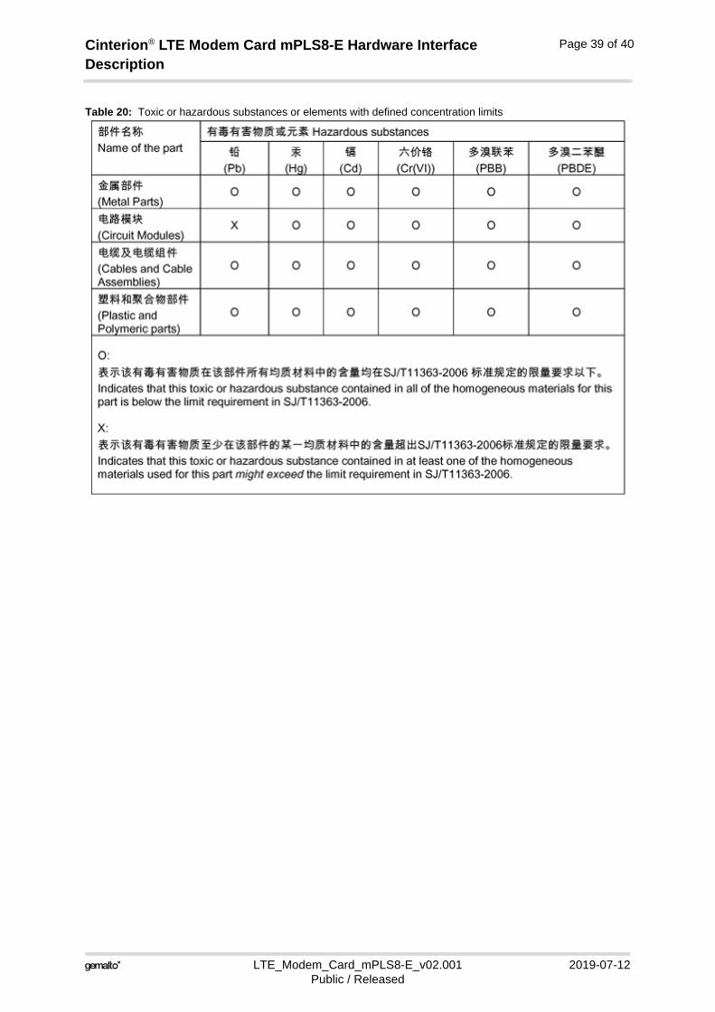
Please see Table 20 for an overview of toxic or hazardous substances or elements that might be contained in product parts in concentrations above the limits defined by SJ/T 11363-2006.
Table 17: Standards of European type approval
Cinterion® LTE Modem Card mPLS8-E Hardware Interface Description
LTE_Modem_Card_mPLS8-E_v02.001 2019-07-12Public / Released
Page 39 of 40
Table 20: Toxic or hazardous substances or elements with defined concentration limits
Cinterion® LTE Modem Card mPLS8-E Hardware Interface Description
LTE_Modem_Card_mPLS8-E_v02.001 2019-07-12Public / Released
Page 40 of 40
5.9 Safety Precaution Notes
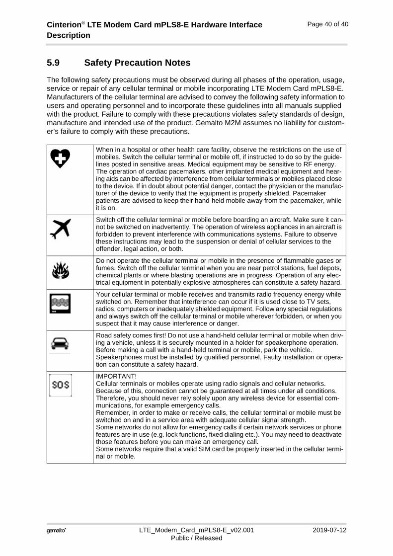
The following safety precautions must be observed during all phases of the operation, usage, service or repair of any cellular terminal or mobile incorporating LTE Modem Card mPLS8-E. Manufacturers of the cellular terminal are advised to convey the following safety information to users and operating personnel and to incorporate these guidelines into all manuals supplied with the product. Failure to comply with these precautions violates safety standards of design, manufacture and intended use of the product. Gemalto M2M assumes no liability for custom-er’s failure to comply with these precautions.
When in a hospital or other health care facility, observe the restrictions on the use of mobiles. Switch the cellular terminal or mobile off, if instructed to do so by the guide-lines posted in sensitive areas. Medical equipment may be sensitive to RF energy. The operation of cardiac pacemakers, other implanted medical equipment and hear-ing aids can be affected by interference from cellular terminals or mobiles placed close to the device. If in doubt about potential danger, contact the physician or the manufac-turer of the device to verify that the equipment is properly shielded. Pacemaker patients are advised to keep their hand-held mobile away from the pacemaker, while it is on.
Switch off the cellular terminal or mobile before boarding an aircraft. Make sure it can-not be switched on inadvertently. The operation of wireless appliances in an aircraft is forbidden to prevent interference with communications systems. Failure to observe these instructions may lead to the suspension or denial of cellular services to the offender, legal action, or both.
Do not operate the cellular terminal or mobile in the presence of flammable gases or fumes. Switch off the cellular terminal when you are near petrol stations, fuel depots, chemical plants or where blasting operations are in progress. Operation of any elec-trical equipment in potentially explosive atmospheres can constitute a safety hazard.
Your cellular terminal or mobile receives and transmits radio frequency energy while switched on. Remember that interference can occur if it is used close to TV sets, radios, computers or inadequately shielded equipment. Follow any special regulations and always switch off the cellular terminal or mobile wherever forbidden, or when you suspect that it may cause interference or danger.
Road safety comes first! Do not use a hand-held cellular terminal or mobile when driv-ing a vehicle, unless it is securely mounted in a holder for speakerphone operation. Before making a call with a hand-held terminal or mobile, park the vehicle. Speakerphones must be installed by qualified personnel. Faulty installation or opera-tion can constitute a safety hazard.
IMPORTANT!Cellular terminals or mobiles operate using radio signals and cellular networks. Because of this, connection cannot be guaranteed at all times under all conditions. Therefore, you should never rely solely upon any wireless device for essential com-munications, for example emergency calls. Remember, in order to make or receive calls, the cellular terminal or mobile must be switched on and in a service area with adequate cellular signal strength. Some networks do not allow for emergency calls if certain network services or phone features are in use (e.g. lock functions, fixed dialing etc.). You may need to deactivate those features before you can make an emergency call.Some networks require that a valid SIM card be properly inserted in the cellular termi-nal or mobile.
41
GEMALTO.COM/M2M
About Gemalto
Since 1996, Gemalto has been pioneering groundbreaking M2M and IoT products that keep our customers on the leading edge of innovation.
We work closely with global mobile network operators to ensure that Cinterion® modules evolve in sync with wireless networks, providing a seamless migration path to protect your IoT technology investment.
Cinterion products integrate seamlessly with Gemalto identity modules, security solutions and licensing and monetization solutions, to streamline development timelines and provide cost efficiencies that improve the bottom line.
As an experienced software provider, we help customers manage connectivity, security and quality of service for the long lifecycle of IoT solutions.
For more information please visitwww.gemalto.com/m2m, www.facebook.com/gemalto, or Follow@gemaltoIoT on Twitter.
Gemalto M2M GmbHSt.-Martin-Str. 6081541 MunichGermany
© G
em
alto
201
9. A
ll rig
hts
rese
rved
. Ge
mal
to,
the
Ge
mal
to lo
go, a
re tr
adem
ark
s a
nd s
ervi
ce m
ark
s of
Gem
alto
an
d ar
e re
gis
tere
d in
cer
tain
cou
ntrie
s.