Embed Size (px)
Citation preview
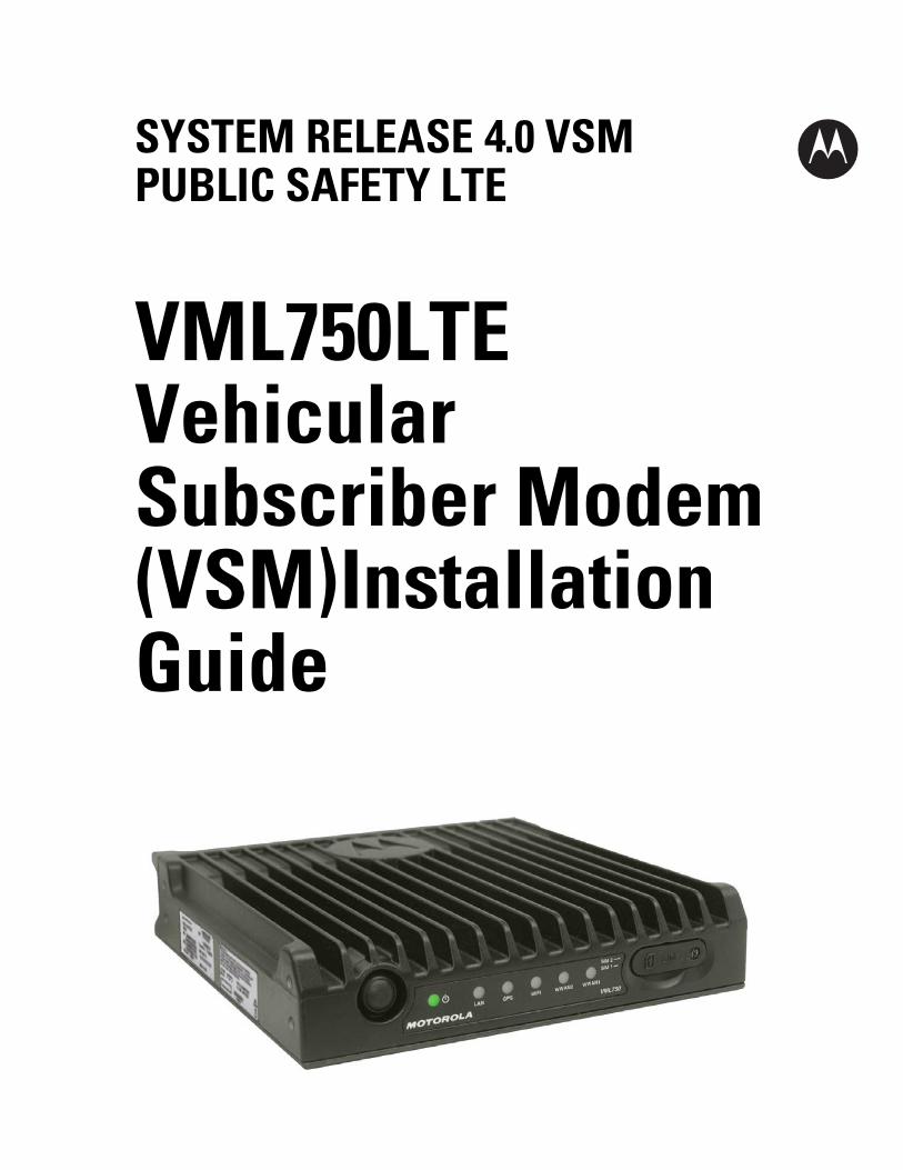
SYSTEM RELEASE 4.0 VSM PUBLIC SAFETY LTE
VML750 LTE Vehicular Subscriber Modem (VSM) Installation Guide
ii
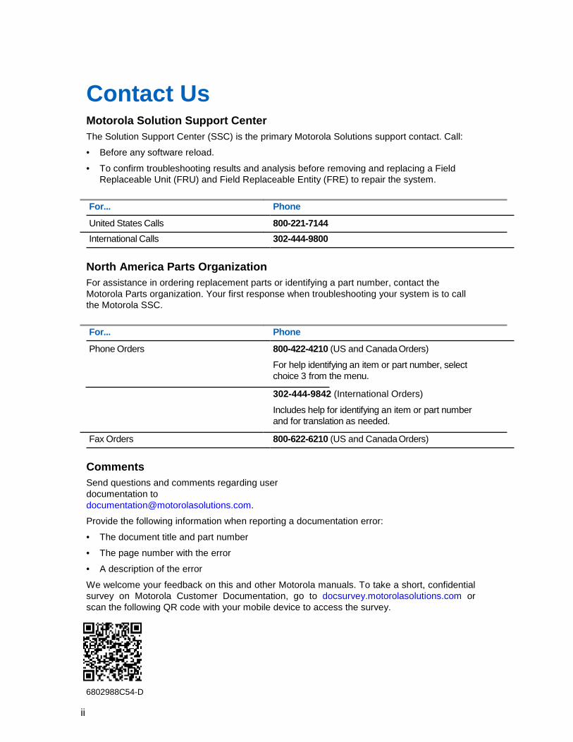
Contact Us Motorola Solution Support Center The Solution Support Center (SSC) is the primary Motorola Solutions support contact. Call:
• Before any software reload.
• To confirm troubleshooting results and analysis before removing and replacing a Field Replaceable Unit (FRU) and Field Replaceable Entity (FRE) to repair the system.
For... Phone
United States Calls 800-221-7144 International Calls 302-444-9800
North America Parts Organization For assistance in ordering replacement parts or identifying a part number, contact the Motorola Parts organization. Your first response when troubleshooting your system is to call the Motorola SSC.
For... Phone
Phone Orders 800-422-4210 (US and Canada Orders)
For help identifying an item or part number, select choice 3 from the menu.
302-444-9842 (International Orders)
Includes help for identifying an item or part number and for translation as needed.
Fax Orders 800-622-6210 (US and Canada Orders)
Comments Send questions and comments regarding user documentation to [email protected].
Provide the following information when reporting a documentation error:
• The document title and part number
• The page number with the error
• A description of the error
We welcome your feedback on this and other Motorola manuals. To take a short, confidential survey on Motorola Customer Documentation, go to docsurvey.motorolasolutions.com or scan the following QR code with your mobile device to access the survey.
6802988C54-D
iii
Contact Us Latest Manual Versions You can verify the latest version of this manual at https://businessonline.motorolasolutions.com.
iv
Copyrights The Motorola products described in this document may include copyrighted Motorola computer programs. Laws in the United States and other countries preserve for Motorola certain exclusive rights for copyrighted computer programs. Accordingly, any copyrighted Motorola computer programs contained in the Motorola products described in this document may not be copied or reproduced in any manner without the express written permission of Motorola. © 2016 Motorola Solutions, Inc. All Rights Reserved
No part of this document may be reproduced, transmitted, stored in a retrieval system, or translated into any language or computer language, in any form or by any means, without the prior written permission of Motorola Solutions, Inc.
Furthermore, the purchase of Motorola products shall not be deemed to grant either directly or by implication, estoppel or otherwise, any license under the copyrights, patents or patent applications of Motorola, except for the normal non-exclusive, royalty-free license to use that arises by operation of law in the sale of a product.
Disclaimer Please note that certain features, facilities, and capabilities described in this document may not be applicable to or licensed for use on a particular system, or may be dependent upon the characteristics of a particular mobile subscriber unit or configuration of certain parameters. Please refer to your Motorola contact for further information.
Trademarks MOTOROLA, MOTO, MOTOROLA SOLUTIONS, and the Stylized M Logo are trademarks or registered trademarks of Motorola Trademark Holdings, LLC and are used under license. All other trademarks are the property of their respective owners.
European Union (EU) Waste of Electrical and Electronic Equipment (WEEE) directive
The European Union's WEEE directive requires that products sold into EU countries must have the crossed out trash bin label on the product (or the package in some cases).
As defined by the WEEE directive, this cross-out trash bin label means that customers and end-users in EU countries should not dispose of electronic and electrical equipment or accessories in household waste.
Customers or end-users in EU countries should contact their local equipment supplier representative or service centre for information about the waste collection system in their country.
v
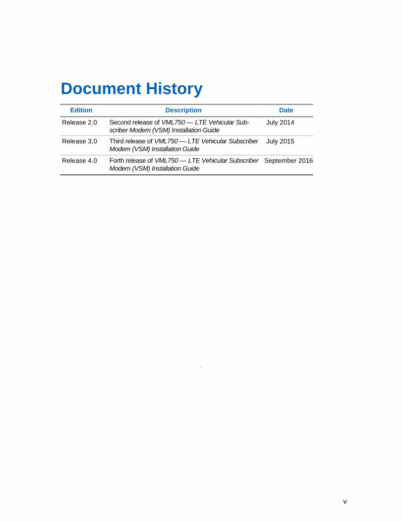
Document History
Edition Description Date
Release 2.0 Second release of VML750 — LTE Vehicular Sub- scriber Modem (VSM) Installation Guide
July 2014
Release 3.0 Third release of VML750 — LTE Vehicular Subscriber Modem (VSM) Installation Guide
July 2015
Release 4.0 Forth release of VML750 — LTE Vehicular Subscriber Modem (VSM) Installation Guide
September 2016
.
vi
Contents Contact Us ........................................................................................................... ii Copyrights .......................................................................................................... iv
Document History ............................................................................................... v
Contents .............................................................................................................. vi List of Figures ................................................................................................... viii List of Tables ...................................................................................................... ix
List of Procedures ................................................... Error! Bookmark not defined. About VML750 LTE Vehicular Subscriber Modem (VSM) Installation Guide . 1
What Is Covered In This Manual? .................................................................................................................... 1 Helpful Background Information ....................................................................................................................... 1 Required Documents for Complete VSM Deployment ..................................................................................... 2 Safety and Regulatory Information ................................................................................................................... 2 FCC Interference .............................................................................................................................................. 2 Legal Notice ..................................................................................................................................................... 2
VML750 Description ............................................................................................ 3
VML750 Models ............................................................................................................................................... 4 VML750 Front Panel ........................................................................................................................................ 5 VML750 Back Panel ......................................................................................................................................... 6
VML750 Installation ............................................................................................. 7
VML750 Unpacking and Inspection .................................................................................................................. 7 Safety and General Information ....................................................................................................................... 7 VML750 Installation Planning ........................................................................................................................... 9
Cable Routing ...................................................................................................................... 10 Cable Holes .................................................................................................................................................... 10
Tools and Equipment ........................................................................................................... 10 Mounting the VML750 Antennas .................................................................................................................... 11
Special Antenna Installation Considerations ....................................................................... 12
Installing Antenna Cables .................................................................................................... 12 VML750 Cables .............................................................................................................................................. 17 Mounting the VML750 .................................................................................................................................... 18 VML750 Cable Routing and Connection ........................................................................................................ 19
Installing the DC Power and Ignition Cable ......................................................................... 19
Installing the LAN/Ethernet Cable ........................................................................................ 21
Installing the Micro USB Cable ............................................................................................ 21 Installing the SIM ............................................................................................................................................ 22 Replacing the CRYPTR Card ......................................................................................................................... 22 Powering Up the Modem ................................................................................................................................ 24
VML750 Troubleshooting Causes and Indicators .......................................... 27
vii
VML750 Troubleshooting ............................................................................................................................... 27 LED Indications .............................................................................................................................................. 29
VML750 Operation ............................................................................................. 31
VLM750 Specifications ..................................................................................... 33
VML750 Physical Specifications .................................................................................................................... 33 VML750 Communication Ports ....................................................................................................................... 33 VML750 RF Ports ........................................................................................................................................... 33 VML750 Power Port ....................................................................................................................................... 33 VML750 LEDs ................................................................................................................................................ 33 VML750 Operating Temperature .................................................................................................................... 33 VML750 Power Specifications ........................................................................................................................ 35 VML750 RF Characteristics ........................................................................................................................... 35 VML750 Replacement Parts List .................................................................................................................... 38 VML750 Kit Replacement Parts List ............................................................................................................... 38 VML750 Approved Antennas and Cables Replacements List ........................................................................ 39
LTE LMR Antennas Mounting Recommendations ......................................... 40
Police Patrol Vehicle Antennas Location Considerations Overview ............................................................... 40
viii
List of Figures Figure 1 VML750 General View .................................................................................................. 3 Figure 2 Front Panel ................................................................................................................... 5 Figure 3 Back Panel ................................................................................................................... 6 Figure 4 VML750 Dimensions .................................................................................................... 9 Figure 5 Schematic Installation Diagram for Sub-models FLN1057A/FLN2057A WWAN1 & WWAN2 Configuration ............................................................................................................. 13 Figure 6 Schematic Installation Diagram for Sub-models WWAN1 only FLN1057A/FLN2057A .............................................................................................................. 14 Figure 7 Schematic Installation Diagram for Sub-models WWAN2 Only FLN1057A/FLN2057A/FLN5057A/FLN5058A ........................................................................... 15 Figure 8 Schematic Installation Diagram for Sub-model FLN5059A ......................................... 16 Figure 9 Available Cables ......................................................................................................... 17 Figure 10 Mounting the VML750 ............................................................................................... 18 Figure 11 DC Power and Ignition Cable Routing Into Engine Compartment ............................. 19 Figure 12 opening the CRYPTR Card Door .............................................................................. 22 Figure 13 Installing the CRYPTR Card ..................................................................................... 24
ix
List of Tables Table 1 Legend for General View ............................................................................................... 3 Table 2 Legend for Front Panel .................................................................................................. 5 Table 3 Legend for Back Panel................................................................................................... 6 Table 4 Troubleshooting the VML750 ....................................................................................... 27 Table 5 LED Indicators Function .............................................................................................. 29 Table 6 VML750 Replacement Parts List .................................................................................. 38

x
6802988C54-D About VML750 LTE Vehicular Subscriber Modem (VSM) Installation Guide
Send Feedback
1
About VML750 LTE Vehicular Subscriber Modem (VSM) Installation Guide The VML750 LTE Vehicular Subscriber Modem (VSM) connects the patrol car, fire apparatus or command vehicle to an LTE network, bringing the benefits of wireless broadband to the vehicle. This installation guide provides a description, and installation, troubleshooting, and operating information.
What Is Covered In This Manual? The VML750 LTE VSM Installation Guide provides general instructions for installing, operating, and troubleshooting the VML750.
The guide is organized as follows:
• VML750 Description provides the product overview.
• VML750 Installation provides unpacking instructions and all required procedures for installing the VML750.
• VML750 Troubleshooting Causes and Indicators provide details regarding possible malfunctions that may occur after first-time installation of the VML750, their probable cause, and the recommended corrective actions.
• Powering Up the Modem provides general information regarding the use of the VML750.
• VLM750 Specifications provides the VML750 modem specifications.
• VML750 Replacement Parts List provides part numbers information for the modem and Antennas.
• LTE LMR Antennas Mounting Recommendations provides procedures for determining the mounting locations for a Public Safety Narrow Band LMR 700/800 MHz antenna and Broad Band LTE 700 MHz Antennas.
Helpful Background Information Motorola offers various courses designed to assist in learning about the system. For information, go to http://www.motorolasolutions.com/training to view the current course offerings and technology paths.
6802988C54-D About VML750 LTE Vehicular Subscriber Modem (VSM) Installation Guide
2 Send Feedback
Required Documents for Complete VSM Deployment To complete the full deployment of the modem, you may need the following documents:
• Information related to VML750 configuration in the VML750 Configuration Guide P/N 6802988C55 at: https://businessonline.motorolasolutions.com
• Information related to VML750 monitoring can be found in the VML750 LTE Vehicle Subscriber Modem (VSM) Status Utility Quick Reference Guide P/N 6802988C79.
• Information related to the device licensing can be found in the Device Licensing Quick Reference Guide P/N 6871024P25 at: https://businessonline.motorolasolutions.com
Safety and Regulatory Information Before installing/using this product, the installer/operator must be familiar with the RF energy awareness information and operating instructions in the “Product Safety and RF Energy Exposure Booklet for Mobile Two-Way Radios Installed in Vehicles or as Fixed Site Control Stations” enclosed with the VML750 LTE Vehicular Subscriber Modem (For USA) Motorola Publication part number 6881095C99 or RF Energy Exposure and Product Safety Guide for Mobile Two-Way Radios installed in Vehicles or as Fixed Site Control Stations P/N 6866537D37 (for rest of regions) to ensure compliance with Radio Frequency (RF) energy exposure limits.
FCC Interference The VML750 is granted with two separate FCC IDs for baseline models: FLN0058A, FLN2058A.
This device complies with Part 15 of the FCC Rules. Operation is subject to the following two conditions:
• This device may not cause harmful interference.
• This device must accept any interference received, including interference that may cause undesired operation.
Changes or modifications made to this product, not expressly approved by Motorola, void the user authority to operate the equipment, per FCC Rule Part 15.21.
Legal Notice The VML750 OSS legal notice is provided by Motorola per request.
6802988C54-D VML750 Description
Send Feedback
3
Chapter 1
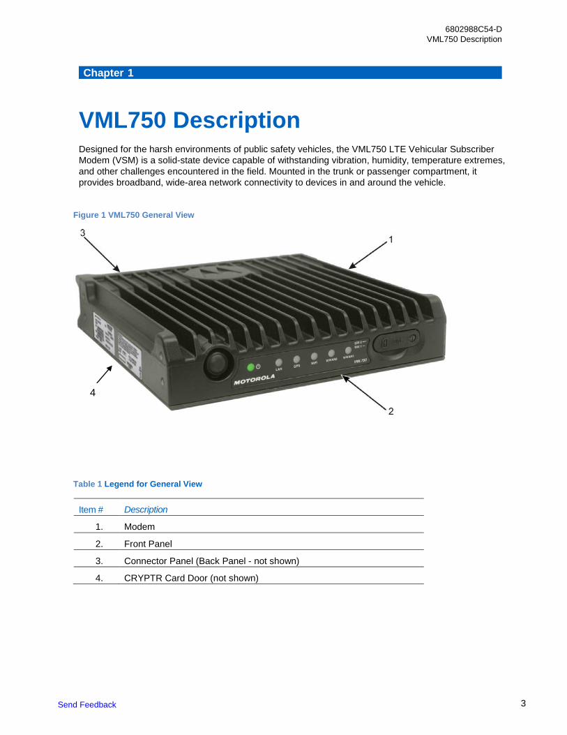
VML750 Description Designed for the harsh environments of public safety vehicles, the VML750 LTE Vehicular Subscriber Modem (VSM) is a solid-state device capable of withstanding vibration, humidity, temperature extremes, and other challenges encountered in the field. Mounted in the trunk or passenger compartment, it provides broadband, wide-area network connectivity to devices in and around the vehicle.
Figure 1 VML750 General View
Table 1 Legend for General View
Item # Description
1. Modem
2. Front Panel
3. Connector Panel (Back Panel - not shown)
4. CRYPTR Card Door (not shown)
4
4
6802988C54-D Chapter 1: VML750 Description
Send Feedback
VML750 Models The Motorola VML750 LTE Vehicular Subscriber Modem (VSM) is a power class 3 device.
The VML750 model F0025 includes the following sub-models:
- FLN1057A: A multi-mode modem that operates in LTE Bands 14/13 and 3G EvDo BC0/BC1. The modem supports WiFi as client and AP as well as GPS for location and support for data encryption (CyrptR).
- FLN2057A: A multi-mode modem that operates in LTE Bands 17/14/13/5/4/2 (Band 13 is hardware ready only) and EvDo BC0/BC1 UMTS B5/B2 GSM. The modem supports WiFi as client and AP as well as GPS for location and support for data encryption (CyrptR).
- FLN5057A: A multi-mode modem that operates in LTE Bands 1, 3, 5, 7 ,8, 28 and UMTS bands 1 and 5. The modem supports WiFi as client and AP as well as GPS for location and support for data encryption (CyrptR).
- FLN5058A: A multi-mode modem that operates in LTE Bands 3, 7 and 20 and UMTS bands 1 and 8. The modem supports WiFi as client and AP as well as GPS for location and support for data encryption (CyrptR).
- FLN5059A: A multi-mode modem that operates in LTE Bands 2, 4 ,7 ,28 and 7 and UMTS bands 2, 4 and 5. The modem supports WiFi as client and AP as well as GPS for location and support for data encryption (CyrptR).
6802988C54-D Chapter 1: VML750 Description
Send Feedback
5
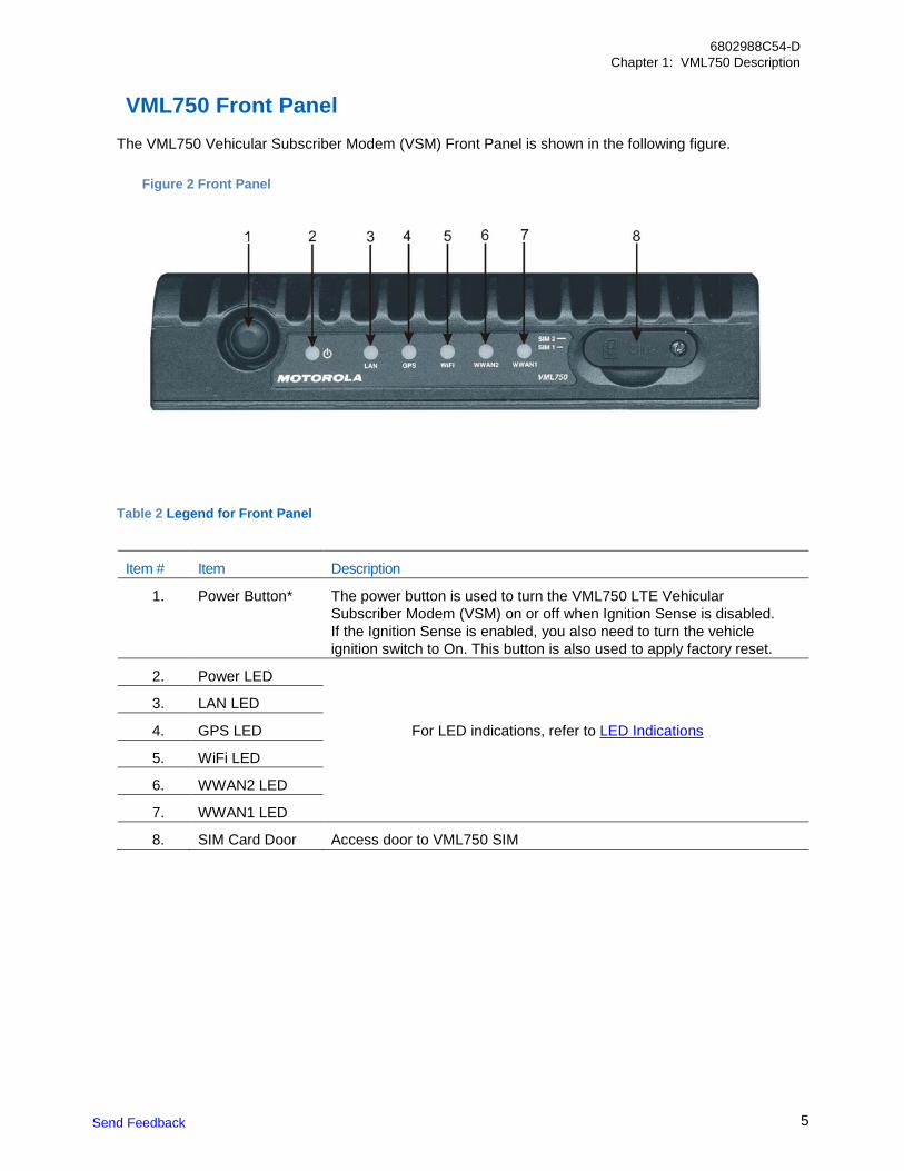
VML750 Front Panel
The VML750 Vehicular Subscriber Modem (VSM) Front Panel is shown in the following figure.
Table 2 Legend for Front Panel
Item # Item Description
1. Power Button* The power button is used to turn the VML750 LTE Vehicular Subscriber Modem (VSM) on or off when Ignition Sense is disabled. If the Ignition Sense is enabled, you also need to turn the vehicle ignition switch to On. This button is also used to apply factory reset.
2. Power LED
3. LAN LED
4. GPS LED For LED indications, refer to LED Indications
5. WiFi LED
6. WWAN2 LED
7. WWAN1 LED
8. SIM Card Door Access door to VML750 SIM
Figure 2 Front Panel
6
6802988C54-D Chapter 1: VML750 Description
Send Feedback
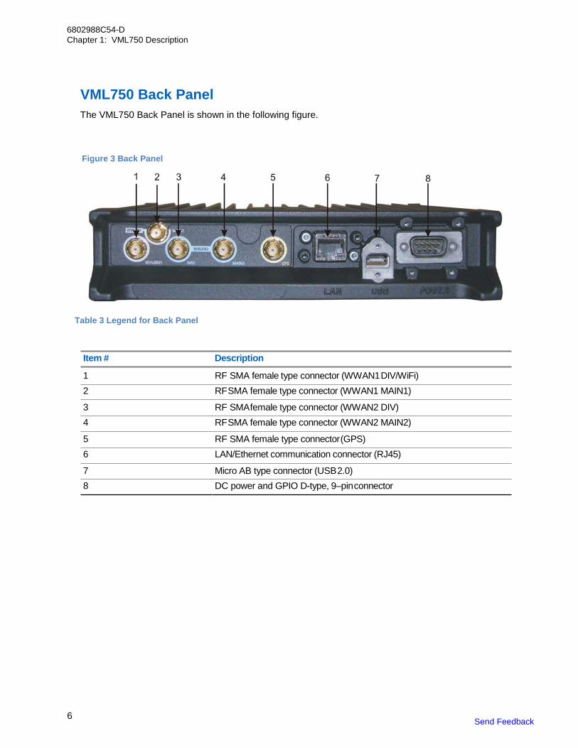
VML750 Back Panel The VML750 Back Panel is shown in the following figure.
Table 3 Legend for Back Panel
Item # Description
1 RF SMA female type connector (WWAN1 DIV/WiFi) 2 RF SMA female type connector (WWAN1 MAIN1)
3 RF SMA female type connector (WWAN2 DIV) 4 RF SMA female type connector (WWAN2 MAIN2)
5 RF SMA female type connector (GPS) 6 LAN/Ethernet communication connector (RJ45)
7 Micro AB type connector (USB 2.0) 8 DC power and GPIO D-type, 9–pin connector
Figure 3 Back Panel
6802988C54-D VML750 Installation
Send Feedback 7
Chapter 2
VML750 Installation Installing the VML750 LTE Vehicular Subscriber Modem (VSM) involves unpacking and inspection, planning, cable routing, installation of the antenna, brackets, VSM, SIM card, CryptR card, and cap, and powering the VSM.
VML750 Unpacking and Inspection Unpack your equipment and check the contents to ensure that you have received all the specified items.
Thoroughly inspect the equipment for shipping damage as soon as possible after delivery. Report any damage you find to your Motorola Customer Service representative immediately.
Safety and General Information
IMPORTANT: This device requires professional installation to satisfy compliance with FCC requirements.
A properly installed VML750 minimizes service calls. When mounting the VML750 components, consider the following factors:
• The mounting surface must have sufficient strength to support the equipment being mounted and to prevent it from becoming loose over time.
• Do not attach components to any part of the vehicle subjected to excessive vibration.
• Do not mount the VML750 unit on a flat surface where the unit could become partially submersed in water.
• The proposed location of the equipment being mounted or wires/cables attached must not interfere with driver/passenger seating or leg space.
• Select a location such that heat from the unit does not damage any wiring or any other plastic or heat-sensitive parts of the automobile.
• Use the supplied mounting hardware.
• Leave sufficient space around the VML750 unit for air flow and installation.
• Select a location that permits routing the cables as directly as possible.
• Ensure that the cables are not stretched, and not subject to heat from the engine, transmission housing, or heating ducts.
• Crimp connectors securely.
• Do not run cables over sharp edges that may cause excessive wear or chaffing of the cable insulation.
• Do not install components in locations where they may cause interference to the operation of the vehicle controls.
• Only qualified personnel may install communication equipment.
• Ensure secure tightening of cable connectors.
8 Send Feedback
6802988C54-D Chapter 2: VML750 Installation
WARNING: VEHICLES EQUIPPED WITH AIR BAGS An air bag inflates with great force. DO NOT place objects, including communications equipment, in the area over the air bag or in the air bag deployment area. Improperly installed communication equipment which causes the air bag to inflate could cause serious injury. If necessary, contact the vehicle manufacturer for air bag information specific to the vehicle.
WARNING: Verify that no vehicle systems are affected by use of the unit, for example, cruise control, ABS breaking, traction control, engine management, direction indicators, and lights.
WARNING: Use existing openings through the firewall to avoid drilling. If drilling is a must, verify not to damage the Vehicle ECMs, fuel lines, brake lines, and/or cable looms.
WARNING: For vehicles equipped with electronic braking systems, see Anti-Skid Braking Precautions, Motorola publication 68P81109E34. Modems installed in vehicles fueled by liquefied petroleum gas must conform to the National Fire Protection Association standard NFPA 58, which applies to vehicles with liquid propane (LP) gas container in the trunk or other sealed off space within the interior of the vehicle.
The NFPA 58 requires the following:
1 The space in which the LP gas container and its fittings are located must be isolated by a seal from the space containing modem equipment.
2 Removable (outside) filling connections must be used.
3 The container space must be vented to the outside.
CAUTION: Installing the VML750 at the end of the vehicle above the exhaust pipe may cause the VML750 to overheat.
CAUTION: Check the required mounting locations. It might be necessary to penetrate the firewall to reach the battery. Before drilling commences, ensure cable clearance on the opposite side of the firewall and do not install the vehicle Electronic Control Modules (ECMs) on the opposite side of the firewall. Protect the cable where it passes through the firewall by using a grommet or similar protective measures. IMPORTANT: Install this product in a vehicle in accordance with the vehicle manufacturer guidelines and the instructions detailed in this manual. Use only the Motorola parts specified in this manual. IMPORTANT: Refer to the Safety Instructions in Product Safety and RF Energy Exposure Booklet for Mobile Two-Way Radios Installed in Vehicles or as Fixed Site Control Stations P/N 6881095C99 (for USA) or RF Energy Exposure and Product Safety Guide for Mobile Two-Way Radios installed in Vehicles or as Fixed Site Control Stations P/N 6866537D37 (for EU).
Send Feedback 9
6802988C54-D Chapter 2: VML750 Installation
VML750 Installation Planning Fast, easy, and safe installation requires careful planning and selecting the proper location. For optimal system performance, follow the instructions and recommendations detailed in this manual.
Perform this process to install the VML750 LTE Vehicular Subscriber Modem (VSM).
Process: 1 Ensure adequate space for the installation.
2 Install the Antennas. See Mounting the VML750 Antennas. Also see the Installation Guide supplied with each antenna.
3 Route the cables. See VML750 Cable Routing and Connection.
4 Install the brackets and the unit. See Installing the VML750 Modem. 5 Connect the DC Power and Ignition cable. See Installing the DC Power and Ignition Cable.
6 Connect the main antenna cables. See Installing Antenna Cables.
7 Connect the LAN/Ethernet cable. See Installing the LAN/Ethernet Cable, or the Micro USB cable, See Installing the Micro USB Cable.
8 Power-up the VML750. See Powering Up the Modem.
The VML750 can be installed on a flat surface or a side wall of a vehicle. Before beginning the installation, make sure that the space available at the installation site is adequate for the modem and its accessories. Each installation configuration may require a different area for mounting the modem without obstruction.
When choosing a location, ensure easy access for installation and replacement of the unit.
Vehicle RF Antennas must be installed in external to the vehicle and in accordance with:
• The requirements of the antenna manufacturer/supplier.
• Instructions provided in installation manuals of other radio devices installed next or used with the VML 750.
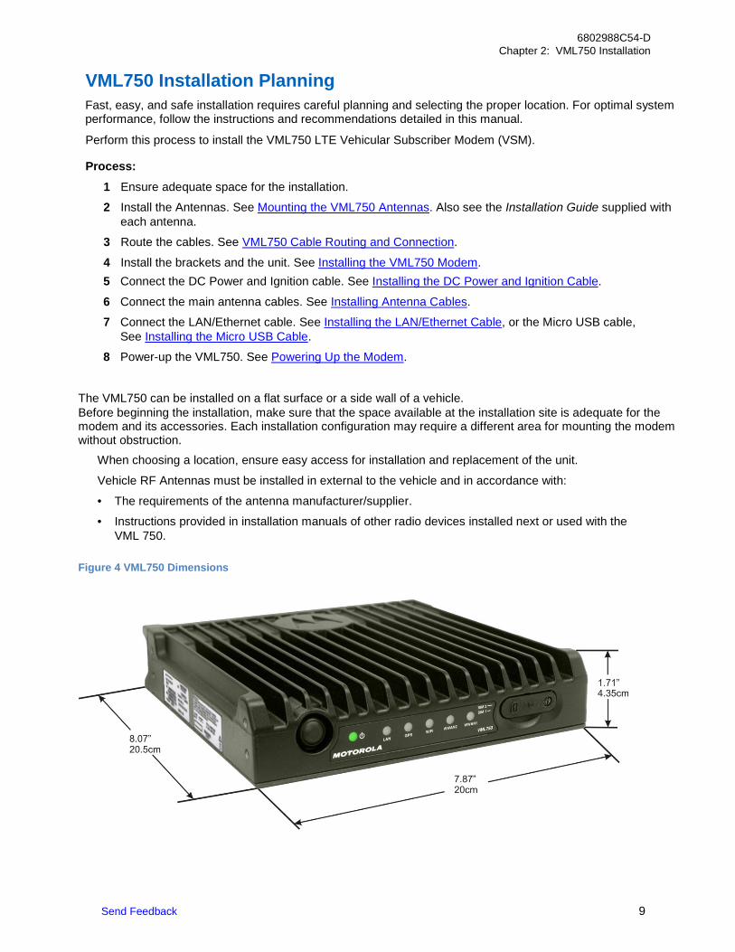
Figure 4 VML750 Dimensions
10 Send Feedback
6802988C54-D Chapter 2: VML750 Installation
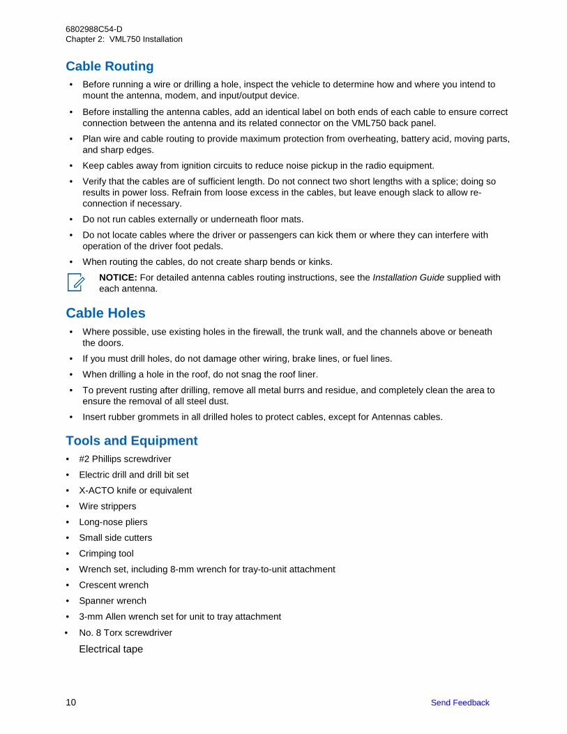
Cable Routing • Before running a wire or drilling a hole, inspect the vehicle to determine how and where you intend to
mount the antenna, modem, and input/output device.
• Before installing the antenna cables, add an identical label on both ends of each cable to ensure correct connection between the antenna and its related connector on the VML750 back panel.
• Plan wire and cable routing to provide maximum protection from overheating, battery acid, moving parts, and sharp edges.
• Keep cables away from ignition circuits to reduce noise pickup in the radio equipment.
• Verify that the cables are of sufficient length. Do not connect two short lengths with a splice; doing so results in power loss. Refrain from loose excess in the cables, but leave enough slack to allow re-connection if necessary.
• Do not run cables externally or underneath floor mats.
• Do not locate cables where the driver or passengers can kick them or where they can interfere with operation of the driver foot pedals.
• When routing the cables, do not create sharp bends or kinks.
NOTICE: For detailed antenna cables routing instructions, see the Installation Guide supplied with each antenna.
Cable Holes • Where possible, use existing holes in the firewall, the trunk wall, and the channels above or beneath
the doors.
• If you must drill holes, do not damage other wiring, brake lines, or fuel lines.
• When drilling a hole in the roof, do not snag the roof liner.
• To prevent rusting after drilling, remove all metal burrs and residue, and completely clean the area to ensure the removal of all steel dust.
• Insert rubber grommets in all drilled holes to protect cables, except for Antennas cables. Tools and Equipment • #2 Phillips screwdriver
• Electric drill and drill bit set
• X-ACTO knife or equivalent
• Wire strippers
• Long-nose pliers
• Small side cutters
• Crimping tool
• Wrench set, including 8-mm wrench for tray-to-unit attachment
• Crescent wrench
• Spanner wrench
• 3-mm Allen wrench set for unit to tray attachment
• No. 8 Torx screwdriver Electrical tape
Send Feedback 11
6802988C54-D Chapter 2: VML750 Installation
Mounting the VML750 Antennas
NOTICE: before installing the antenna cables, add an identical label on both ends of each cable to ensure correct connection between the antenna and its related connector on the VML750 back panel.
The VML750 antenna is used to enhance the reception capability in poor reception areas and support Multiple Input Multiple Output (MIMO) modes for LTE.
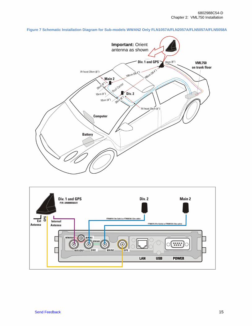
Two identical Antennas are used; one for WWAN2 Main and one for WWAN2 div. The Antennas can be provided with 12-ft (P/N: FTN6070A) or 17-ft (P/N: FTN0073A) coaxial cable.
To complete the public network installation, base with cup antenna is used for WiFi connectivity on WWAN1 WiFi/Div and GPS reception (P/N: AN000036A01). The antenna is constructed of three Antennas:
• Internal antenna - for WiFi (to be connected to WWAN1 diversity) • External antenna – Whip connected to Main1 (for use only with B14)
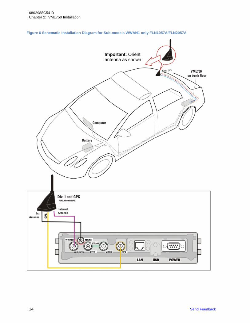
• GPS active antenna (to be connected to GPS port) IMPORTANT: Use the following guidelines for antenna mounting to ensure best performance and avoid signal reduction and interference:
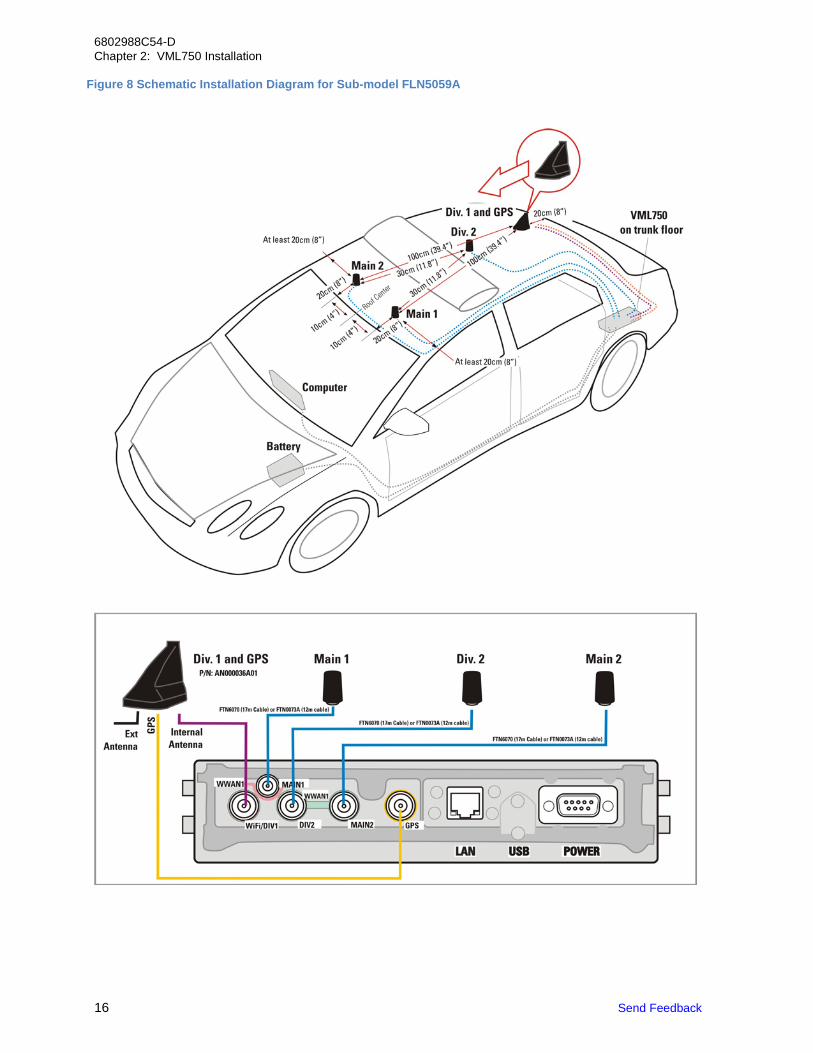
1. When installing antenna Main 1 or Main 2 or Div 2, keep a clear radius of more than 20 cm (8") from other Antennas.
2. When installing antenna Main 1 or Main 2 or Div 2, keep a distance of more than 20 cm (8") from the front edge of the car roof. Install the Antennas in a distance of about 10 cm (4") from the center line crossing the length of the car.
3. Keep a clear distance of more than 30 cm (11.8") between antenna Div. 2 and Main 1.
4. Keep a clear distance of more than 30 cm (11.8") between antenna Div. 2 and Main 2.
5. Keep a clear distance of more than 100 cm (39.4") between antenna Div. 1 and Main 1.
6. Keep a clear distance of more than 100 cm (39.4") between antenna Div. 1 and Main 2.
7. When installing antenna Div. 2 at the center line of the roof, keep a distance of more than 20 cm (8") from the rear edge of the car roof.
IMPORTANT: To assure optimum performance and compliance with RF Energy Safety standards, these antenna installation guidelines and instructions are limited to metal-body vehicles with appropriate ground planes and take into account the potential exposure of back seat passengers and bystanders outside the vehicle.
12 Send Feedback
6802988C54-D Chapter 2: VML750 Installation
Special Antenna Installation Considerations
WARNING: To comply with safety regulations, the distance between Antennas and people sitting inside the vehicle must be more than 8 inches (20 cm).
CAUTION: If your vehicle is equipped with Public Safety Narrow Band (PSNB) equipment, when installing the Antennas, provide a minimum distance of 78 inches (198 cm) between the PSNB antenna and any VML750 antenna to ensure coexistence between all systems.
Main Antenna
IMPORTANT: Install the antenna on a flat metal surface with a minimum size of 24 inches (61 cm) x 24 inches (61 cm).
NOTICE: Install the Private network main antenna (when applicable) and the Public network main antenna on the vehicle roof, preferably in the center front side of it. Ensure that the vehicle roof material is metal. If not, use a 2 ft x 2 ft metal ground plane and mount the antenna in its center. For best performance, keep a minimum distance of 36 inches (91.44 cm) between this antenna and any other antenna.
Installing Antenna Cables Perform this procedure to install antenna cables for public and private network configurations.
Procedure:
1 Connect the Internal cable connector to the WWAN1 WiFi/DIV port on the VML750 LTE Vehicular Subscriber Modem (VSM) connector panel. Connect the GPS cable connector to the GPS port on the VML750 connector panel. Form a service loop for the flexible cables coming out of the antenna bottom near the cable exit to contain any excess cable length. Form these service loops with a minimum bend radius of 1 inch (2.54 cm). If needed, form a second service loop for the excess length of the jumper cables near the VML750 with minimum bend radius of 3 inches (7.63 cm). Use plastic cable ties to secure the cable.
NOTICE: The combo antenna is provided with three flexible coaxial cables coming out of the antenna bottom side (two threads for internal and GPS are used). Two 12-ft/17-ft coaxial cables are also provided to connect between the internal and GPS threads and the modem connectors.
2 For the Main and Diversity Antennas, connect the RF cable from the antenna to WWAN2 main and WWAN2 DIV.
IMPORTANT: Do not use pliers or any other metallic tool for tightening - only Hand-tighten. Fully tighten the antenna cable connector and verify it is fastened.
3 For the private network configuration, connect the connector of the cable marked External to the WWAN1 Main port on the VML750 connector panel.
IMPORTANT: To protect any unused connectors (WWAN2, LAN/Ethernet, USB) on the back of the VML750 LTE Vehicular Subscriber Modem (VSM), screw the caps provided in the installation kit onto these unused ports.
Send Feedback 13
6802988C54-D Chapter 2: VML750 Installation
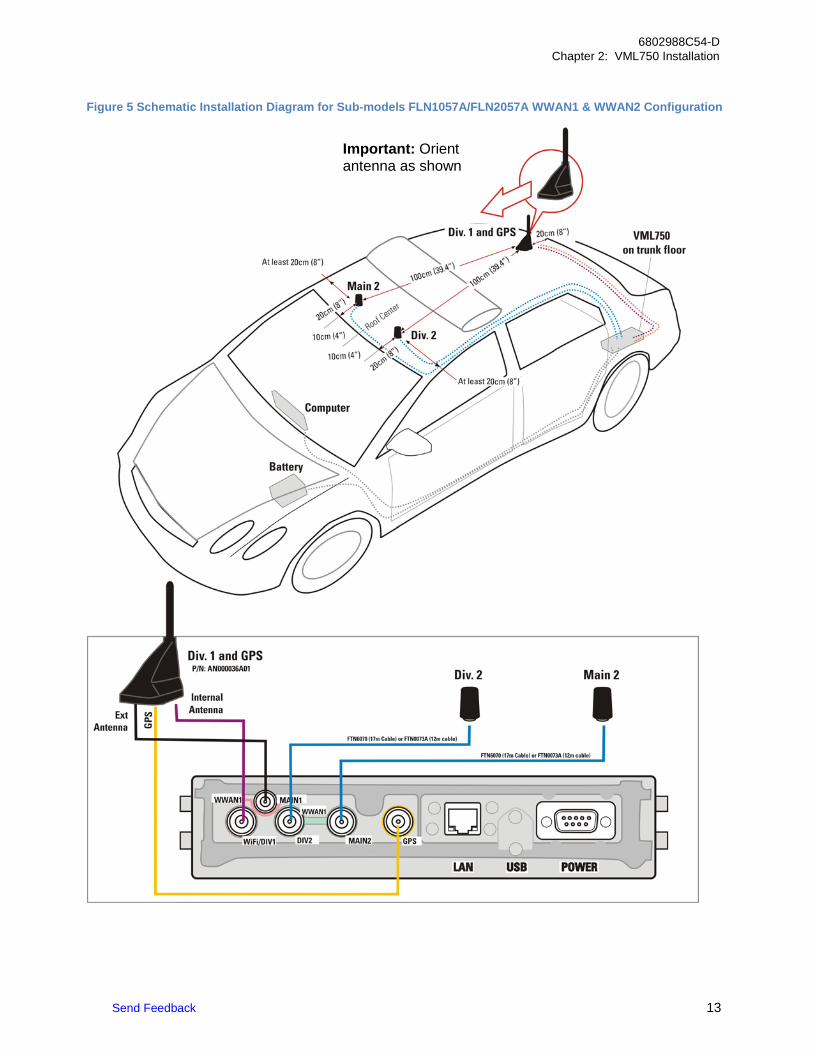
Figure 5 Schematic Installation Diagram for Sub-models FLN1057A/FLN2057A WWAN1 & WWAN2 Configuration
Important: Orient antenna as shown
14 Send Feedback
6802988C54-D Chapter 2: VML750 Installation
Figure 6 Schematic Installation Diagram for Sub-models WWAN1 only FLN1057A/FLN2057A
Important: Orient antenna as shown
Send Feedback 15
6802988C54-D Chapter 2: VML750 Installation
Figure 7 Schematic Installation Diagram for Sub-models WWAN2 Only FLN1057A/FLN2057A/FLN5057A/FLN5058A
Important: Orient antenna as shown
16 Send Feedback
6802988C54-D Chapter 2: VML750 Installation
Figure 8 Schematic Installation Diagram for Sub-model FLN5059A
Send Feedback 17
6802988C54-D Chapter 2: VML750 Installation
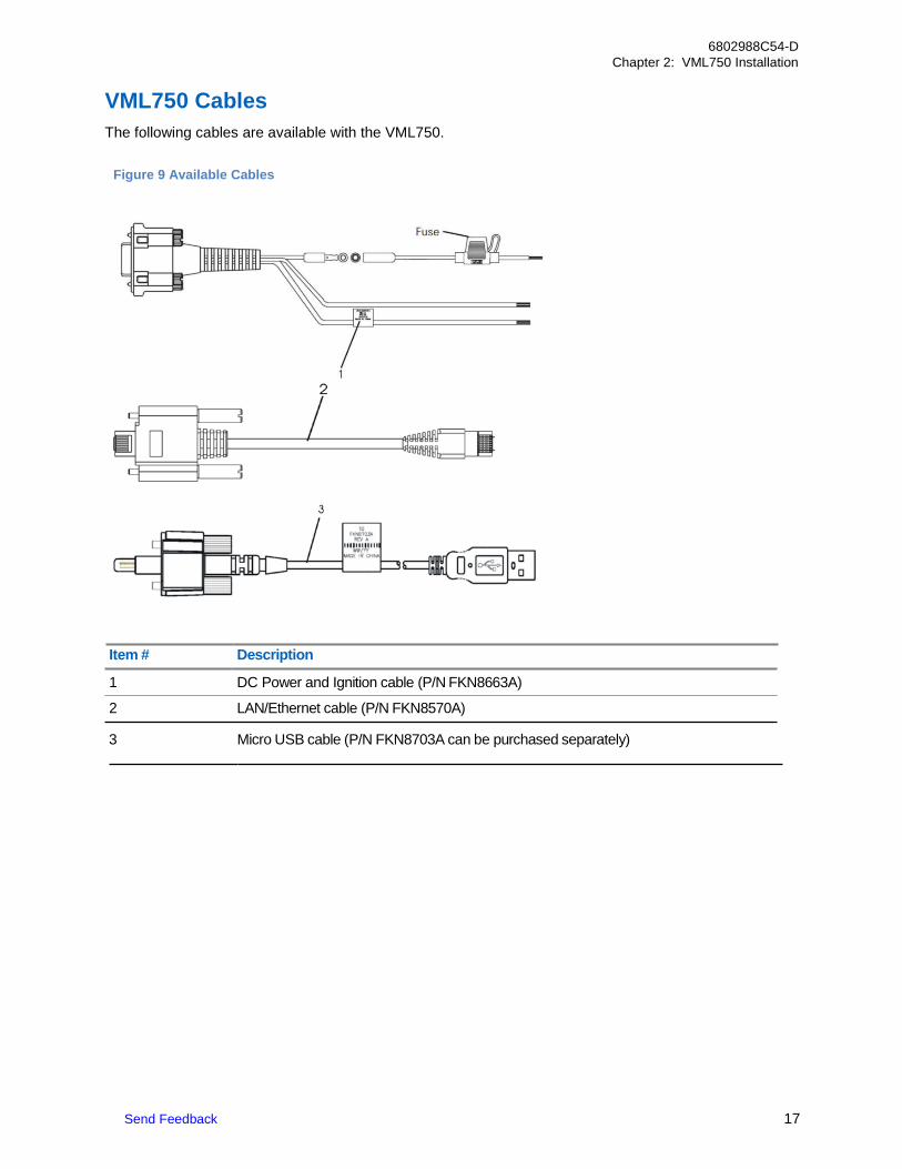
VML750 Cables The following cables are available with the VML750.
Item # Description
1 DC Power and Ignition cable (P/N FKN8663A)
2 LAN/Ethernet cable (P/N FKN8570A)
3 Micro USB cable (P/N FKN8703A can be purchased separately)
Figure 9 Available Cables
18 Send Feedback
6802988C54-D Chapter 2: VML750 Installation
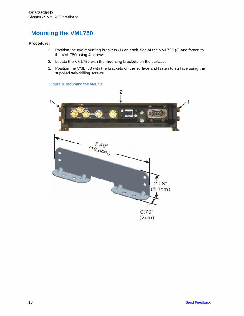
Mounting the VML750
Procedure:
1. Position the two mounting brackets (1) on each side of the VML750 (2) and fasten to the VML750 using 4 screws.
2. Locate the VML750 with the mounting brackets on the surface.
3. Position the VML750 with the brackets on the surface and fasten to surface using the supplied self-drilling screws.
Figure 10 Mounting the VML750
Send Feedback 19
6802988C54-D Chapter 2: VML750 Installation
VML750 Cable Routing and Connection
This section describes installing, routing, and connecting the VML750 LTE Vehicular Subscriber Modem (VSM) cables.
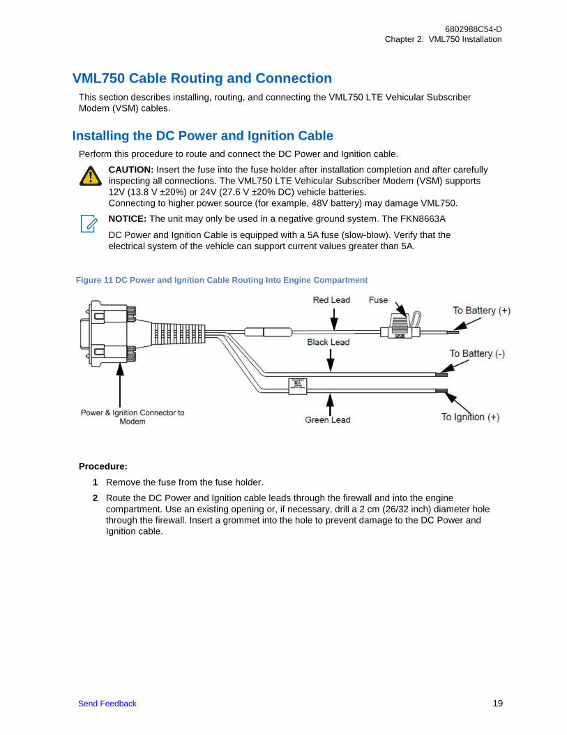
Installing the DC Power and Ignition Cable
Perform this procedure to route and connect the DC Power and Ignition cable.
CAUTION: Insert the fuse into the fuse holder after installation completion and after carefully inspecting all connections. The VML750 LTE Vehicular Subscriber Modem (VSM) supports 12V (13.8 V ±20%) or 24V (27.6 V ±20% DC) vehicle batteries. Connecting to higher power source (for example, 48V battery) may damage VML750.
NOTICE: The unit may only be used in a negative ground system. The FKN8663A
DC Power and Ignition Cable is equipped with a 5A fuse (slow-blow). Verify that the electrical system of the vehicle can support current values greater than 5A.
Procedure:
1 Remove the fuse from the fuse holder.
2 Route the DC Power and Ignition cable leads through the firewall and into the engine compartment. Use an existing opening or, if necessary, drill a 2 cm (26/32 inch) diameter hole through the firewall. Insert a grommet into the hole to prevent damage to the DC Power and Ignition cable.
Figure 11 DC Power and Ignition Cable Routing Into Engine Compartment
20 Send Feedback
6802988C54-D Chapter 2: VML750 Installation
3 On the engine side of the firewall, connect the black lead to the negative (-) battery terminal.
4 On the engine side of the firewall, perform the following actions to connect the red (A+) lead to the vehicle battery:
a Verify that the fuse holder is at a distance of 20-30 cm (7.87-11.8 inches) from the connection point, ensuring that it is not close to any hot engine component.
b Mount the fuse holder using the provided mount, and dress wires as necessary. Connect the red lead plug adaptor (on the fuse holder) to the matching receptacle on the red lead of the DC Power and Ignition cable.
c Connect the red lead of the DC Power and Ignition cable to the positive (+) battery terminal. Cable tie the wire every 10 cm (4 inches) along its length. Do not tie to existing vehicle cables.
d Insert the fuse into the fuse holder.
5 Verify that the cables in the engine compartment do not obstruct any of the vehicle controls or touch hot or moveable parts of the engine.
6 For ignition installation, perform the following actions:
a Consult the vehicle documentation to locate the ignition wire.
b Verify that the voltage is high with the ignition on, during start (cranking), accessory, and while vehicle is running. When the ignition is off, the voltage is zero.
c Connect the green lead of the DC Power and Ignition cable to ignition (+). Cable tie the wire every 10 cm (4 inches) along its length. Do not tie to existing vehicle systems.
7 Connect the DC Power and Ignition cable connector to POWER connector on the VML750 Connector panel. Fasten the connector using the four fastening screws.
Send Feedback 21
6802988C54-D Chapter 2: VML750 Installation
Installing the LAN/Ethernet Cable Perform this procedure to install the LAN/Ethernet cable.
Procedure:
1 Connect the LAN/Ethernet cable from the LAN connector on the VML750 LTE Vehicular Subscriber Modem (VSM) Connector panel to your vehicle Mobile Data Terminal.
CAUTION: Do not use pliers or any other metallic tool for tightening. Hand- tighten only. Fully tighten the LAN/Ethernet cable connector and verify it is fastened.
2 Follow the LAN/Ethernet cable 8 +/–2 inches (20 +/–5 cm) from where it attaches to the VML750 and secure it to the vehicle body.
Installing the Micro USB Cable Perform this procedure if you are not installing the LAN/Ethernet cable.
Procedure:
1 Connect the Micro USB cable from the Micro USB connector on the VML750 LTE Vehicular Subscriber Modem (VSM) Connector panel to your vehicle Mobile Data Terminal USB connector.
CAUTION: Do not use pliers or any other metallic tool for tightening. Hands tighten only. Fully tighten the Micro USB cable connector and verify it is fastened.
2 Follow the Micro USB cable 8 +/–2 inches (20 +/–5 cm) from where it attaches to the VML750 and secure it to the vehicle body.
22 Send Feedback
6802988C54-D Chapter 2: VML750 Installation
Installing the SIM If your VML750 is intended for use on your private Motorola LTE network, you are provided with a Motorola LTE SIM card (to be inserted into SIM1 slot). If your VSM is intended to home on a public carrier LTE network, you must obtain a SIM card from that public carrier and insert it into SIM2 slot.
The VML750 can be used a WiFi modem without the need for a SIM card. When using the VML750 as a WiFi modem, the VML75 must be configured prior to use. For VML750 configuration, refer to VML750 Configuration Guide (6802988C55) at https://businessonline.motorolasolutions.com.
Procedure:
1 Locate the SIM card door on the front right side of the VML750. Unscrew the door and put to the side.
NOTICE: If a SIM card is in the slot, your LTE modem has been staged for you (seeVML750 Configuration Guide PN 6802988C55 if required); skip to step 4.
2 Locate the SIM card Motorola or your public carrier provided. Hold the card so that the metal contacts are facing down.
3 Insert the card into the SIM slot until you feel it 'click' into place.
NOTICE: SIM 1 slot is for private network. SIM 2 slot is for public carrier network.
4 Close the door and screw it into place. Tightened the screw so that the door does not move. Replacing the CRYPTR Card Perform this procedure to replace the CRYPTR card in the VML750.
CAUTION: Disconnect your VML750 from the power source before performing this procedure.
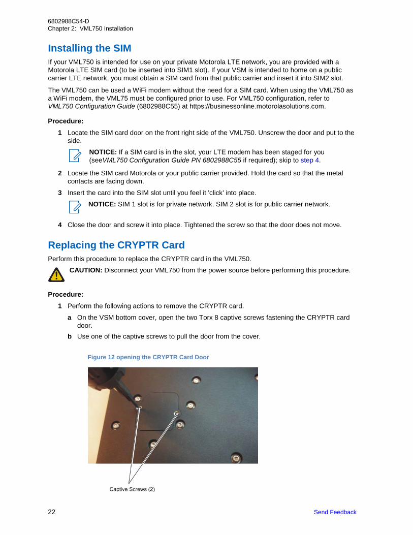
Procedure: 1 Perform the following actions to remove the CRYPTR card.
a On the VSM bottom cover, open the two Torx 8 captive screws fastening the CRYPTR card door.
b Use one of the captive screws to pull the door from the cover.
Figure 12 opening the CRYPTR Card Door
Send Feedback 23
6802988C54-D Chapter 2: VML750 Installation
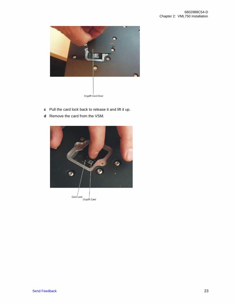
c Pull the card lock back to release it and lift it up.
d Remove the card from the VSM.
24 Send Feedback
6802988C54-D Chapter 2: VML750 Installation
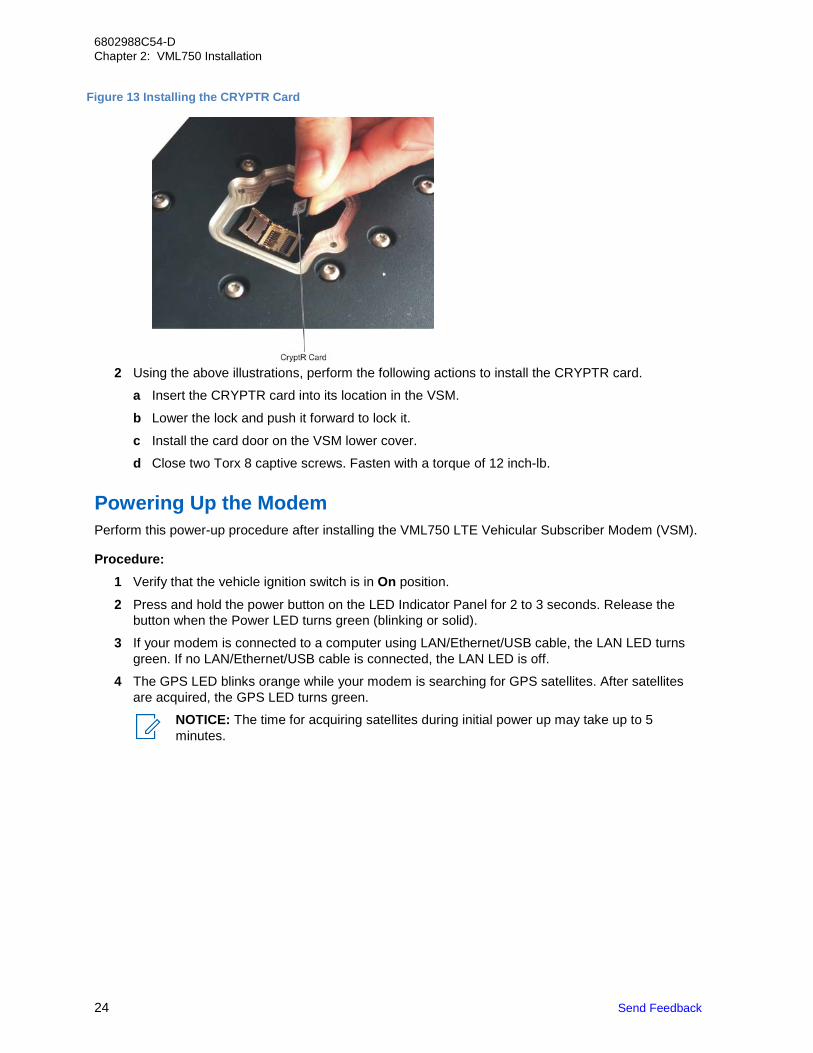
Figure 13 Installing the CRYPTR Card
2 Using the above illustrations, perform the following actions to install the CRYPTR card.
a Insert the CRYPTR card into its location in the VSM.
b Lower the lock and push it forward to lock it.
c Install the card door on the VSM lower cover.
d Close two Torx 8 captive screws. Fasten with a torque of 12 inch-lb. Powering Up the Modem Perform this power-up procedure after installing the VML750 LTE Vehicular Subscriber Modem (VSM).
Procedure:
1 Verify that the vehicle ignition switch is in On position.
2 Press and hold the power button on the LED Indicator Panel for 2 to 3 seconds. Release the button when the Power LED turns green (blinking or solid).
3 If your modem is connected to a computer using LAN/Ethernet/USB cable, the LAN LED turns green. If no LAN/Ethernet/USB cable is connected, the LAN LED is off.
4 The GPS LED blinks orange while your modem is searching for GPS satellites. After satellites are acquired, the GPS LED turns green.
NOTICE: The time for acquiring satellites during initial power up may take up to 5 minutes.
Send Feedback 25
6802988C54-D Chapter 2: VML750 Installation
5 WiFi LED is tuned off until WiFi configuration was performed. See the VML750 Configuration
Guide, PN 6802988C55.
6 After configuring the modem to WiFi Access Point mode, the WiFi LED turns green. When data is transferred, the WiFi LED blinks green.
7 If a SIM card is inserted and the SIM door is closed and you are in an LTE coverage area, the following sequence takes place:
a LTE LED blinks orange while the modem searches for the LTE network.
b LTE LED blinks green while registering to the network.
c LTE LED is solid green after registration and activation.
8 If your VML750 is equipped to support LTE, activate it on the associated LTE network (your private PS LTE network or on the public carrier network). Contact the manager of your network (Motorola, public carrier, or your internal technical support) and provide the SIM card identifier number, called the IMSI. This identifier can be found on the plastic credit card frame for the SIM.
NOTICE: The time for registering and activating your account may vary and could typically take up to 2 minutes.
• If the SIM door is not closed, the LTE LED rapidly blinks red.
• If SIM card is not inserted, the LTE LED blinks red.

This page intentionally left blank.
6802988C54-D VML750 Troubleshooting Causes and Indicators
Send Feedback 27
Chapter 3
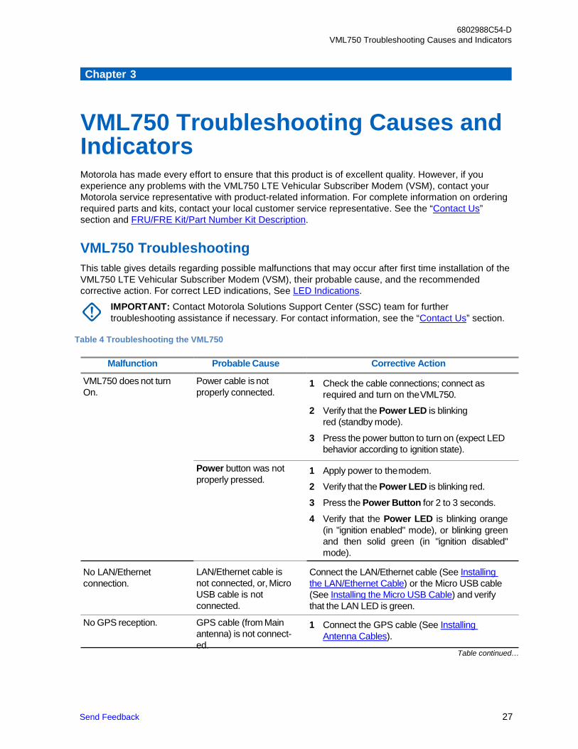
VML750 Troubleshooting Causes and Indicators Motorola has made every effort to ensure that this product is of excellent quality. However, if you experience any problems with the VML750 LTE Vehicular Subscriber Modem (VSM), contact your Motorola service representative with product-related information. For complete information on ordering required parts and kits, contact your local customer service representative. See the “Contact Us” section and FRU/FRE Kit/Part Number Kit Description.
VML750 Troubleshooting This table gives details regarding possible malfunctions that may occur after first time installation of the VML750 LTE Vehicular Subscriber Modem (VSM), their probable cause, and the recommended corrective action. For correct LED indications, See LED Indications.
IMPORTANT: Contact Motorola Solutions Support Center (SSC) team for further troubleshooting assistance if necessary. For contact information, see the “Contact Us” section.
Table 4 Troubleshooting the VML750
Malfunction Probable Cause Corrective Action
VML750 does not turn On.
Power cable is not properly connected.
Power button was not properly pressed.
1 Check the cable connections; connect as
required and turn on the VML750.
2 Verify that the Power LED is blinking red (standby mode).
3 Press the power button to turn on (expect LED behavior according to ignition state).
1 Apply power to the modem.
2 Verify that the Power LED is blinking red.
3 Press the Power Button for 2 to 3 seconds.
4 Verify that the Power LED is blinking orange (in "ignition enabled" mode), or blinking green and then solid green (in "ignition disabled" mode).
No LAN/Ethernet connection.
LAN/Ethernet cable is not connected, or, Micro USB cable is not connected.
Connect the LAN/Ethernet cable (See Installing the LAN/Ethernet Cable) or the Micro USB cable (See Installing the Micro USB Cable) and verify that the LAN LED is green.
No GPS reception. GPS cable (from Main antenna) is not connect- ed.
1 Connect the GPS cable (See Installing Antenna Cables).
Table continued…
6802988C54-D Chapter 3: VML750 Troubleshooting Causes and Indicators
28
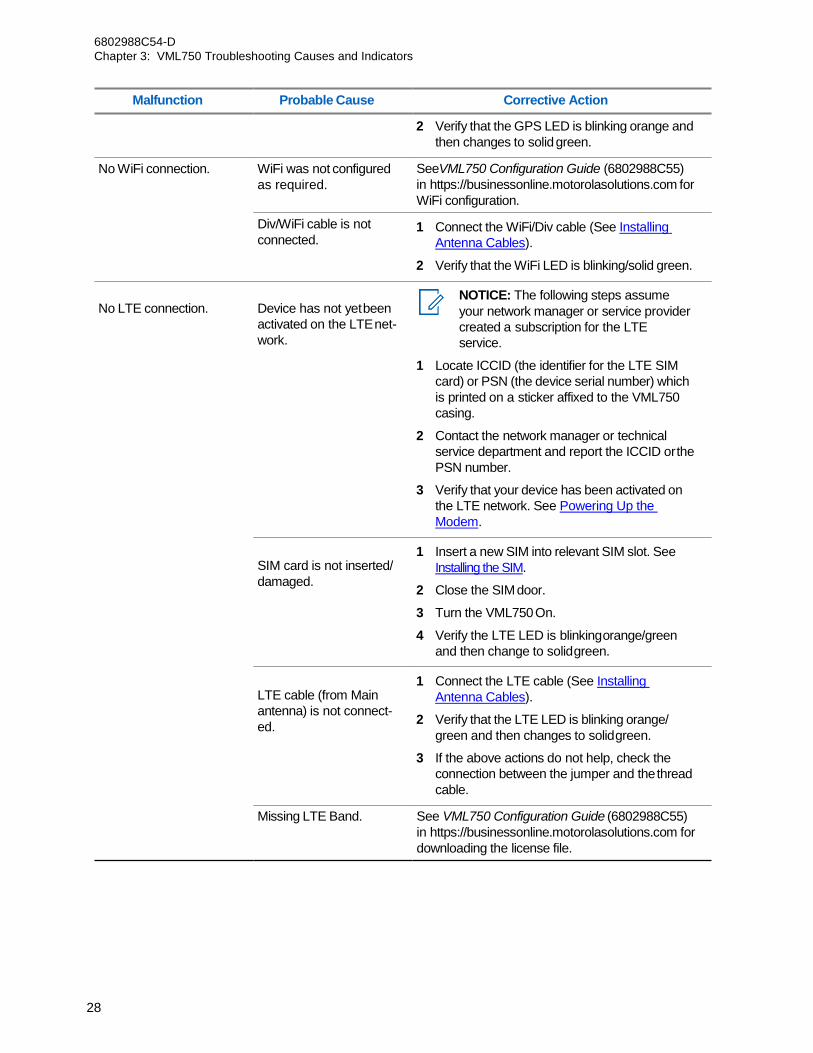
Malfunction Probable Cause Corrective Action
No WiFi connection. WiFi was not configured as required.
Div/WiFi cable is not connected.
No LTE connection. Device has not yet been activated on the LTE net- work.
SIM card is not inserted/ damaged.
LTE cable (from Main antenna) is not connect- ed.
2 Verify that the GPS LED is blinking orange and then changes to solid green.
SeeVML750 Configuration Guide (6802988C55) in https://businessonline.motorolasolutions.com for WiFi configuration.
1 Connect the WiFi/Div cable (See Installing Antenna Cables).
2 Verify that the WiFi LED is blinking/solid green.
NOTICE: The following steps assume your network manager or service provider created a subscription for the LTE service.
1 Locate ICCID (the identifier for the LTE SIM card) or PSN (the device serial number) which is printed on a sticker affixed to the VML750 casing.
2 Contact the network manager or technical service department and report the ICCID or the PSN number.
3 Verify that your device has been activated on the LTE network. See Powering Up the Modem.
1 Insert a new SIM into relevant SIM slot. See
Installing the SIM.
2 Close the SIM door.
3 Turn the VML750 On.
4 Verify the LTE LED is blinking orange/green and then change to solid green.
1 Connect the LTE cable (See Installing
Antenna Cables).
2 Verify that the LTE LED is blinking orange/ green and then changes to solid green.
3 If the above actions do not help, check the connection between the jumper and the thread cable.
Missing LTE Band. See VML750 Configuration Guide (6802988C55) in https://businessonline.motorolasolutions.com for downloading the license file.
Send Feedback 29
6802988C54-D Chapter 3: VML750 Troubleshooting Causes and Indicators
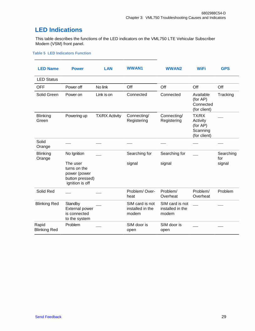
LED Indications This table describes the functions of the LED indicators on the VML750 LTE Vehicular Subscriber Modem (VSM) front panel.
Table 5 LED Indicators Function
LED Name Power LAN WWAN1 WWAN2 WiFi GPS
LED Status
OFF Power off No link Off Off Off Off
Solid Green Power on Link is on Connected Connected Available Tracking (for AP) Connected (for client) Blinking Powering up TX/RX Activity Connecting/ Connecting/ TX/RX Green Registering Registering Activity
(for AP) Scanning (for client) Solid Orange
Blinking Orange
No Ignition Searching for Searching for Searching for
The user signal signal signal turns on the power (power button pressed)
ignition is off
Solid Red Problem/ Over- Problem/ Problem/ Problem heat Overheat Overheat Blinking Red Standby SIM card is not SIM card is not External power installed in the installed in the is connected modem modem to the system Rapid Problem SIM door is SIM door is Blinking Red open open

This page intentionally left blank.
6802988C54-D VML750 Operation
31
Chapter 4
VML750 Operation After installing the VML750 LTE Vehicular Subscriber Modem (VSM) in your vehicle, it must be configured for proper operation. To configure your modem, seeVML750 Configuration Guide PN 6802988C55. After configuring the modem, it should be turned on automatically upon your vehicle ignition and operate properly.
If you detect any malfunction in the VML750 operation, See VML750 Troubleshooting Causes and Indicators.

This page intentionally left blank.
6802988C54-D VLM750 Specifications
33
Appendix A
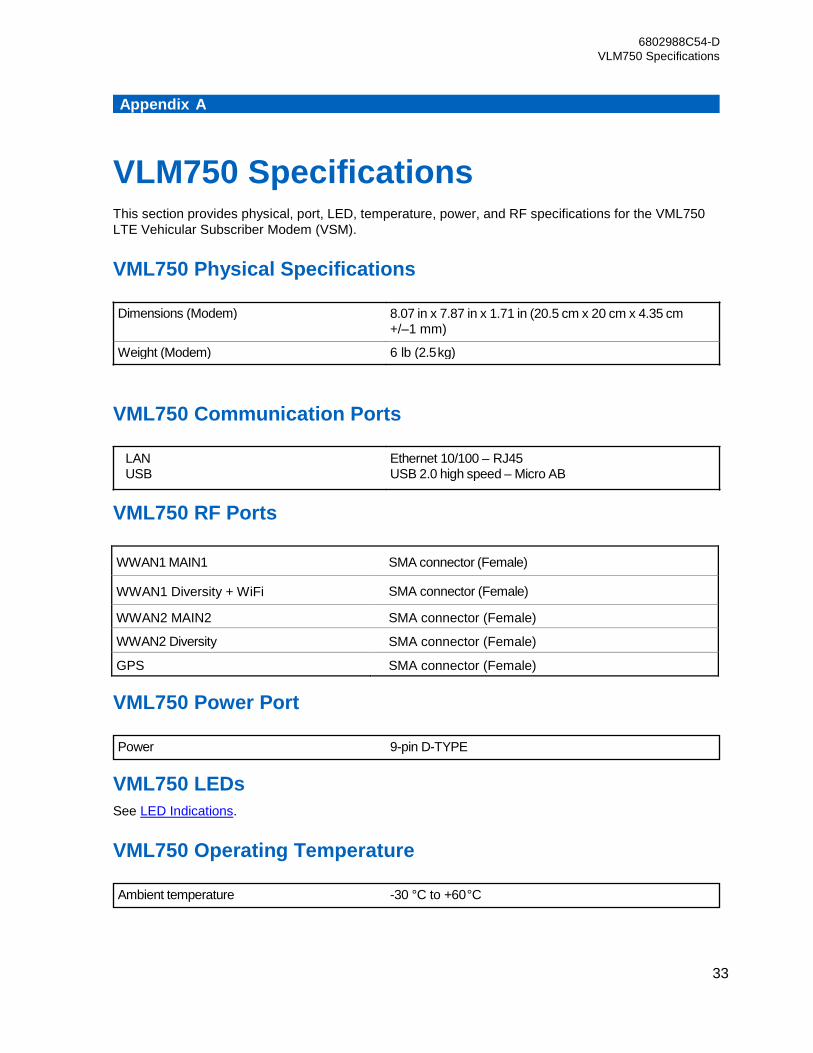
VLM750 Specifications This section provides physical, port, LED, temperature, power, and RF specifications for the VML750 LTE Vehicular Subscriber Modem (VSM).
VML750 Physical Specifications
VML750 Communication Ports
VML750 RF Ports
WWAN1 MAIN1 SMA connector (Female)
WWAN1 Diversity + WiFi SMA connector (Female)
WWAN2 MAIN2 SMA connector (Female)
WWAN2 Diversity SMA connector (Female)
GPS SMA connector (Female)
VML750 Power Port
VML750 LEDs See LED Indications.
VML750 Operating Temperature
Power 9-pin D-TYPE
Ambient temperature -30 °C to +60 °C
Ethernet 10/100 – RJ45 USB 2.0 high speed – Micro AB
LAN USB
Dimensions (Modem) 8.07 in x 7.87 in x 1.71 in (20.5 cm x 20 cm x 4.35 cm +/–1 mm)
Weight (Modem) 6 lb (2.5 kg)

6802988C54-D Appendix A: VLM750 Specifications
34
6802988C54-D Appendix A: VLM750 Specifications
35
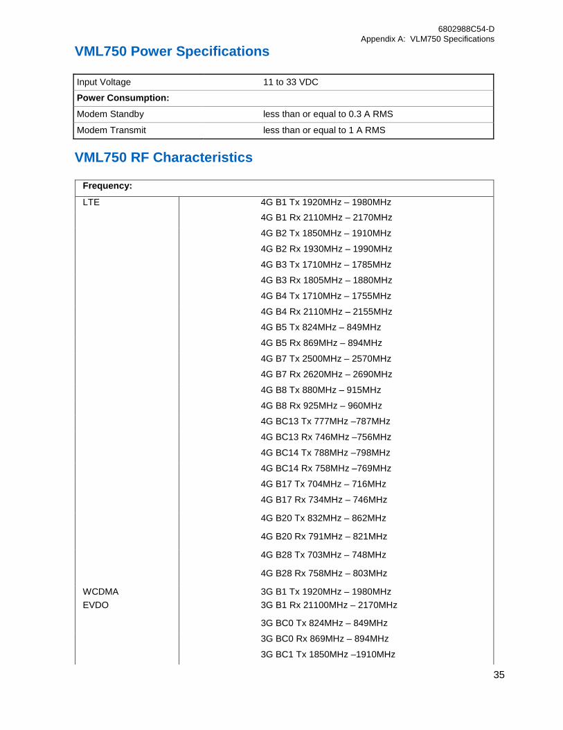
VML750 Power Specifications
Input Voltage 11 to 33 VDC
Power Consumption:
Modem Standby less than or equal to 0.3 A RMS
Modem Transmit less than or equal to 1 A RMS
VML750 RF Characteristics
Frequency:
LTE 4G B1 Tx 1920MHz – 1980MHz 4G B1 Rx 2110MHz – 2170MHz
4G B2 Tx 1850MHz – 1910MHz
4G B2 Rx 1930MHz – 1990MHz
4G B3 Tx 1710MHz – 1785MHz
4G B3 Rx 1805MHz – 1880MHz
4G B4 Tx 1710MHz – 1755MHz
4G B4 Rx 2110MHz – 2155MHz
4G B5 Tx 824MHz – 849MHz
4G B5 Rx 869MHz – 894MHz
4G B7 Tx 2500MHz – 2570MHz
4G B7 Rx 2620MHz – 2690MHz
4G B8 Tx 880MHz – 915MHz
4G B8 Rx 925MHz – 960MHz
4G BC13 Tx 777MHz –787MHz
4G BC13 Rx 746MHz –756MHz
4G BC14 Tx 788MHz –798MHz
4G BC14 Rx 758MHz –769MHz
4G B17 Tx 704MHz – 716MHz
4G B17 Rx 734MHz – 746MHz
4G B20 Tx 832MHz – 862MHz
4G B20 Rx 791MHz – 821MHz
4G B28 Tx 703MHz – 748MHz
4G B28 Rx 758MHz – 803MHz
WCDMA 3G B1 Tx 1920MHz – 1980MHz EVDO 3G B1 Rx 21100MHz – 2170MHz
3G BC0 Tx 824MHz – 849MHz
3G BC0 Rx 869MHz – 894MHz
3G BC1 Tx 1850MHz –1910MHz
6802988C54-D Appendix A: VLM750 Specifications
36
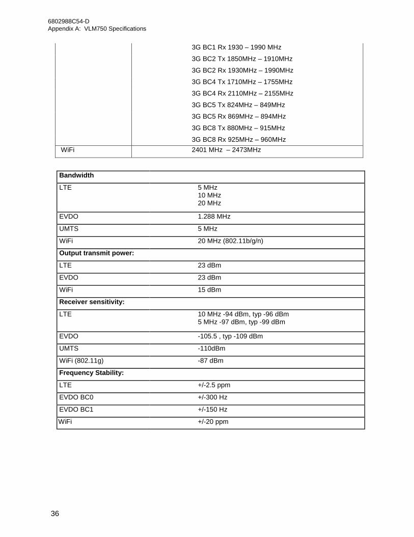
3G BC1 Rx 1930 – 1990 MHz
3G BC2 Tx 1850MHz – 1910MHz
3G BC2 Rx 1930MHz – 1990MHz
3G BC4 Tx 1710MHz – 1755MHz
3G BC4 Rx 2110MHz – 2155MHz
3G BC5 Tx 824MHz – 849MHz
3G BC5 Rx 869MHz – 894MHz
3G BC8 Tx 880MHz – 915MHz
3G BC8 Rx 925MHz – 960MHz WiFi 2401 MHz – 2473MHz
Bandwidth
LTE 5 MHz 10 MHz 20 MHz
EVDO 1.288 MHz
UMTS 5 MHz
WiFi 20 MHz (802.11b/g/n)
Output transmit power:
LTE 23 dBm
EVDO 23 dBm
WiFi 15 dBm
Receiver sensitivity:
LTE 10 MHz -94 dBm, typ -96 dBm 5 MHz -97 dBm, typ -99 dBm
EVDO -105.5 , typ -109 dBm
UMTS -110dBm
WiFi (802.11g) -87 dBm
Frequency Stability:
LTE +/-2.5 ppm
EVDO BC0 +/-300 Hz
EVDO BC1 +/-150 Hz
WiFi +/-20 ppm

6802988C54-D Appendix A: VLM750 Specifications
37
This page intentionally left blank.
6802988C54-D Appendix B: VML750 FRU/FRE List
38 Send Feedback
Appendix B
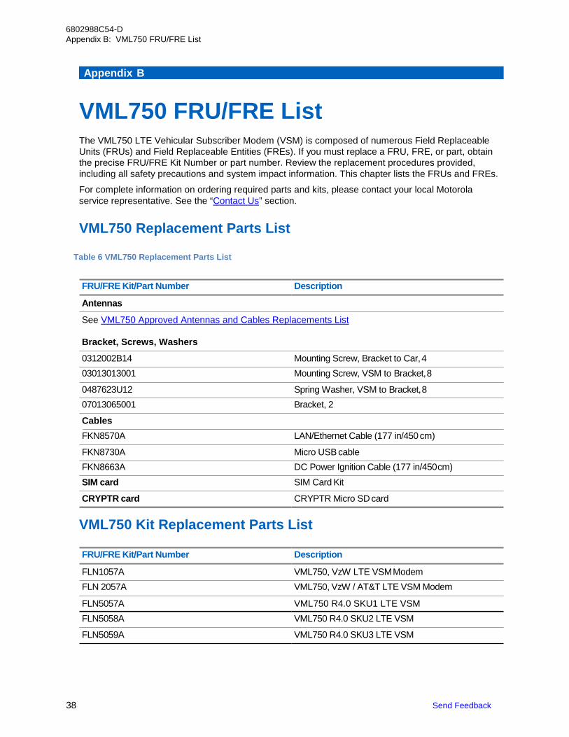
VML750 FRU/FRE List The VML750 LTE Vehicular Subscriber Modem (VSM) is composed of numerous Field Replaceable Units (FRUs) and Field Replaceable Entities (FREs). If you must replace a FRU, FRE, or part, obtain the precise FRU/FRE Kit Number or part number. Review the replacement procedures provided, including all safety precautions and system impact information. This chapter lists the FRUs and FREs.
For complete information on ordering required parts and kits, please contact your local Motorola service representative. See the “Contact Us” section.
VML750 Replacement Parts List
Table 6 VML750 Replacement Parts List
FRU/FRE Kit/Part Number Description
Antennas
See VML750 Approved Antennas and Cables Replacements List
Bracket, Screws, Washers
0312002B14 Mounting Screw, Bracket to Car, 4 03013013001 Mounting Screw, VSM to Bracket, 8
0487623U12 Spring Washer, VSM to Bracket, 8 07013065001 Bracket, 2
Cables FKN8570A LAN/Ethernet Cable (177 in/450 cm)
FKN8730A Micro USB cable FKN8663A DC Power Ignition Cable (177 in/450 cm) SIM card SIM Card Kit
CRYPTR card CRYPTR Micro SD card
VML750 Kit Replacement Parts List
FRU/FRE Kit/Part Number Description
FLN1057A VML750, VzW LTE VSM Modem FLN 2057A VML750, VzW / AT&T LTE VSM Modem
FLN5057A VML750 R4.0 SKU1 LTE VSM FLN5058A VML750 R4.0 SKU2 LTE VSM
FLN5059A VML750 R4.0 SKU3 LTE VSM
6802988C54-D VML750 FRU/FRE List
39
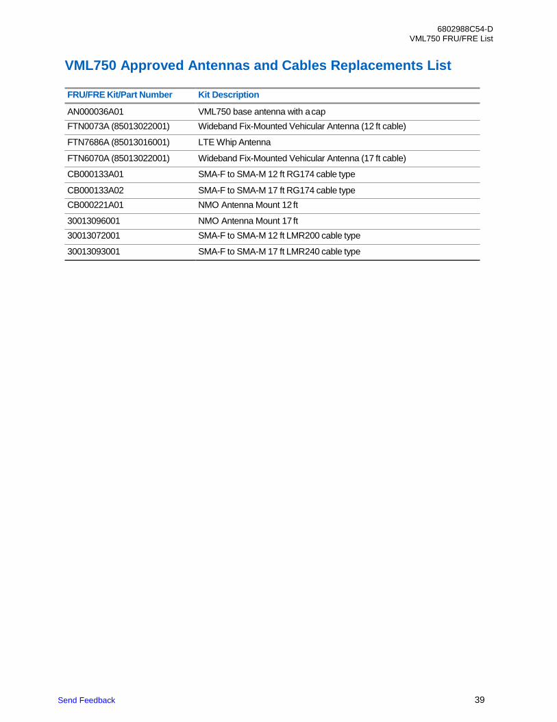
VML750 Approved Antennas and Cables Replacements List
FRU/FRE Kit/Part Number Kit Description
AN000036A01 VML750 base antenna with a cap FTN0073A (85013022001) Wideband Fix-Mounted Vehicular Antenna (12 ft cable)
FTN7686A (85013016001) LTE Whip Antenna
FTN6070A (85013022001) Wideband Fix-Mounted Vehicular Antenna (17 ft cable)
CB000133A01 SMA-F to SMA-M 12 ft RG174 cable type
CB000133A02 SMA-F to SMA-M 17 ft RG174 cable type CB000221A01 NMO Antenna Mount 12 ft
30013096001 NMO Antenna Mount 17 ft 30013072001 SMA-F to SMA-M 12 ft LMR200 cable type
30013093001 SMA-F to SMA-M 17 ft LMR240 cable type
Send Feedback
40 Send Feedback
6802988C54-D Appendix C: LTE LMR Antennas Mounting Recommendations
Appendix C
LTE LMR Antennas Mounting Recommendations This appendix provides procedures for determining the mounting locations for a Public Safety Narrow Band (PSNB) Land Mobile Radio (LMR) 700/800 MHz antenna and Broad Band (BB) LTE 700 MHz Antennas.
The following procedures are given:
• Police patrol vehicle with a PSNB antenna and a standard BB antenna.
• Bus with a PSNB antenna and a low profile BB antenna
Police Patrol Vehicle Antennas Location Considerations Overview Individually select the Antennas mounting location for every vehicle before starting the actual installation process. The following list gives general recommendations for determining the mounting location of Public Safety Narrow Band (PSNB) and Broad Band (BB) Antennas based on several key considerations:
• Keep a minimum distance of 8 in (20 cm) between the LTE [BB] Antennas; including WiFi to anyother antenna and any potential bystander (for bystander safely).
• Follow the guidelines in the installation and safety manuals of the Land Mobile Radios (LMRs)(PSNB) with regards to mounting locations and operation of radio in the presence of bystanders (forbystander safety).
• Keep a minimum separation of 39.4 in (100 cm) between the PSNB and BB LTE Antennas.

6802988C54-D LTE LMR Antennas Mounting Recommendations
41
This page intentionally left blank.