Embed Size (px)
Citation preview

v1.0
Hit U4 LTE modem
HitU4 LTE
Page 2 of 29
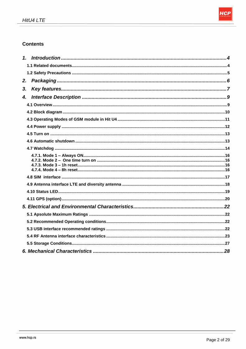
Contents
1. Introduction ....................................................................................................................... 4
1.1 Related documents........................................................................................................................................ 4
1.2 Safety Precautions ........................................................................................................................................ 5
2. Packaging .......................................................................................................................... 6
3. Key features....................................................................................................................... 7
4. Interface Description ........................................................................................................ 9
4.1 Overview ......................................................................................................................................................... 9
4.2 Block diagram .............................................................................................................................................. 10
4.3 Operating Modes of GSM module in Hit U4 .............................................................................................. 11
4.4 Power supply ............................................................................................................................................... 12
4.5 Turn on ......................................................................................................................................................... 13
4.6 Automatic shutdown ................................................................................................................................... 13
4.7 Watchdog ..................................................................................................................................................... 14
4.7.1. Mode 1 – Always ON............................................................................................................................ 16 4.7.2. Mode 2 – One time turn on ................................................................................................................ 16 4.7.3. Mode 3 – 1h reset ................................................................................................................................. 16 4.7.4. Mode 4 – 8h reset ................................................................................................................................. 16
4.8 SIM interface ............................................................................................................................................... 17
4.9 Antenna interface LTE and diversity antenna .......................................................................................... 18
4.10 Status LED .................................................................................................................................................. 19
4.11 GPS (option) ............................................................................................................................................... 20
5. Electrical and Environmental Characteristics ................................................................. 22
5.1 Apsolute Maximum Ratings ....................................................................................................................... 22
5.2 Recommended Operating conditions ........................................................................................................ 22
5.3 USB interface recommended ratings ........................................................................................................ 22
5.4 RF Antenna interface characteristics ........................................................................................................ 23
5.5 Storage Conditions...................................................................................................................................... 27
6. Mechanical Characteristics .............................................................................................. 28
HitU4 LTE
Page 3 of 29
Copyright Transmittal, reproduction, dissemination and/or editing of this document as well as utilization of its contents and communication thereof to others without express authorization are prohibited. Offenders will be held liable for payment of damages. All rights created by patent grant or registration of a utility model or design patent are reserved. Copyright © 2017, HCP d.o.o
Trademark notice Cinterion is registered trademark of ©Gemalto M2M GmbH in the Germany and/or other countries. All other registered trademarks or trademarks mentioned in this document are property of their respective owners. DISCLAIMER:
In case of any failure you should contact the nearest authorized service center. HCP d.o.o. is not responsible for any damage caused by improper use of the device (physical damage, overvoltage…) using spare parts that are not original or interventions by unauthorized persons. Device is in accordance with the applicable safety standards, it is forbidden and dangerous to inject any kind of things and liquid into the device.
HCP d.o.o. reserves the right to make changes in specifications and other information contained in this document without notice, and users should be consulted in all cases with HCP to determine whether any such changes made. HCP shall not be liable for technical or editorial errors or omissions contained in this document: nor for incidental or consequential damages incurred when using this guide.
In no event shall HCP its directors, officers, employees, agents or distributors be liable for any consequential damages (including damages for loss of business profits and business information, business interruption or any other pecuniary loss) arising out of the use of this manual or product, even if HCP has been informed of the possibility of such damages.
This document contains information on safety that is protected by copyright. All rights reserved. No part of this document may be photocopied, reproduced or translated into another language without the prior written permission of HCP d.o.o.
HIGH RISK ACTIVITIES:
HCP products are not fault – tolerant nor designed, manufactured or intended for use or resale as control equipment in hazardous environments requiring fail – safe performance, such as in the operation of nuclear facilities, aircraft navigation, air traffic control, direct life support machines or weapons systems in which the failure of hardware or software(firmware) could lead directly to death, personal injury or severe physical or environmental damage („High Risk Activities‟). HCP and its suppliers specifically disclaim any expressed or implied warranty of fitness for High Risk Activities.
HitU4 LTE
Page 4 of 29
1. Introduction
This document describes the hardware of HCP LTE terminal Hit U4, with interface specifications, electrical and mechanical characteristics. Hit U4 terminal is intended to use in variety of M2M application.
1.1 Related documents
[1] PLS8-E AT command set [2] PLS8-E Hardware interface description
HitU4 LTE
Page 5 of 29
1.2 Safety Precautions
Safety precautions must be observed during all phases of the operation, usage, service or repair of any cellular terminal from HCP d.o.o.
Failure to comply with these precautions violates safety standards of design, manufacture and intended use of the product. HCP d.o.o assumes no liability for customer‟s failure to comply with these precautions.
When in hospitals or other health care facilities, observe the restrictions on the use of mobiles. Switch off the cellular terminal or mobile if to be instructed to do so by the guidelines posted in sensitive areas. Medical equipment may be sensitive to RF energy. The operation of cardiac pacemakers, other implanted medical equipment and hearing aids can be affected by interference from cellular terminals or mobiles placed close to the device. If in doubt about potential danger, contact the physician or the manufacturer of the device to verify that the equipment is properly shielded. Pacemaker patients are advised to keep their hand-held mobile away from the pacemaker, while it is on. This personal subgroup always should check the distance to the mobile
Switch off the cellular terminal or mobile before boarding an aircraft. Make sure it cannot be switched on inadvertently. The operation of wireless appliances in an aircraft is forbidden to prevent interference with communications systems. Failure to observe these instructions may lead to the suspension or denial of cellular services to the offender, legal action, or both. Check the local and actual laws about these themes.
Do not operate the cellular terminal or mobile in the presence of flammable gases or fumes. Switch off the cellular terminal when you are near petrol stations, fuel depots, chemical plants or where blasting operations are in progress. Operation of any electrical equipment in potentially explosive atmospheres can constitute a safety hazard.
Your cellular terminal or mobile receives and transmits radio frequency energy while switched on. Remember that interference can occur if it is used close to TV sets,radios, computers or inadequ- ately shielded equipment. Follow any special regulations and always switch off the cellular terminal or mobile wherever forbidden, or when you suspect that it may cause interference or danger.
Road safety comes first! Do not use a hand-held cellular terminal or mobile while driving a vehicle unless it is securely mounted in a holder for speakerphone operation. Before making a call with a hand-held terminal or mobile park the vehicle. Speakerphones must be installed by qualified personnel. Faulty installation or operation can constitute a safety hazard. Check the actual and local laws about these themes.
IMPORTANT! Cellular terminals or mobiles operate using radio signals and cellular networks. In that case connections cannot be guaranteed at all times under all conditions. Therefore, you should never rely solely upon any wireless device for essential communications, for example emergency calls. Remember, in order to make calls or receive calls the cellular terminal or mobile must be switched on in a service area with adequate cellular signal strength. Some networks do not allow for emergency calls if certain network services or phone features are in use (e.g. lock functions, fixed dialing etc.). You may need to deactivate those features before you can make an emergency call. Some networks require a valid SIM card to be properly inserted in the cellular terminal or mobile.
If a power supply unit is used to supply the device it must meet the demands placed on SELV circuits in accordance with EN60950. The maximum permissible connection length between the device and the supply source should not exceed 3m.
According to the guidelines for human exposure to radio frequency energy, an antenna connected to the FME jack of the device should be placed at least 20cm away from human bodies.
HitU4 LTE
Page 6 of 29
2. Packaging
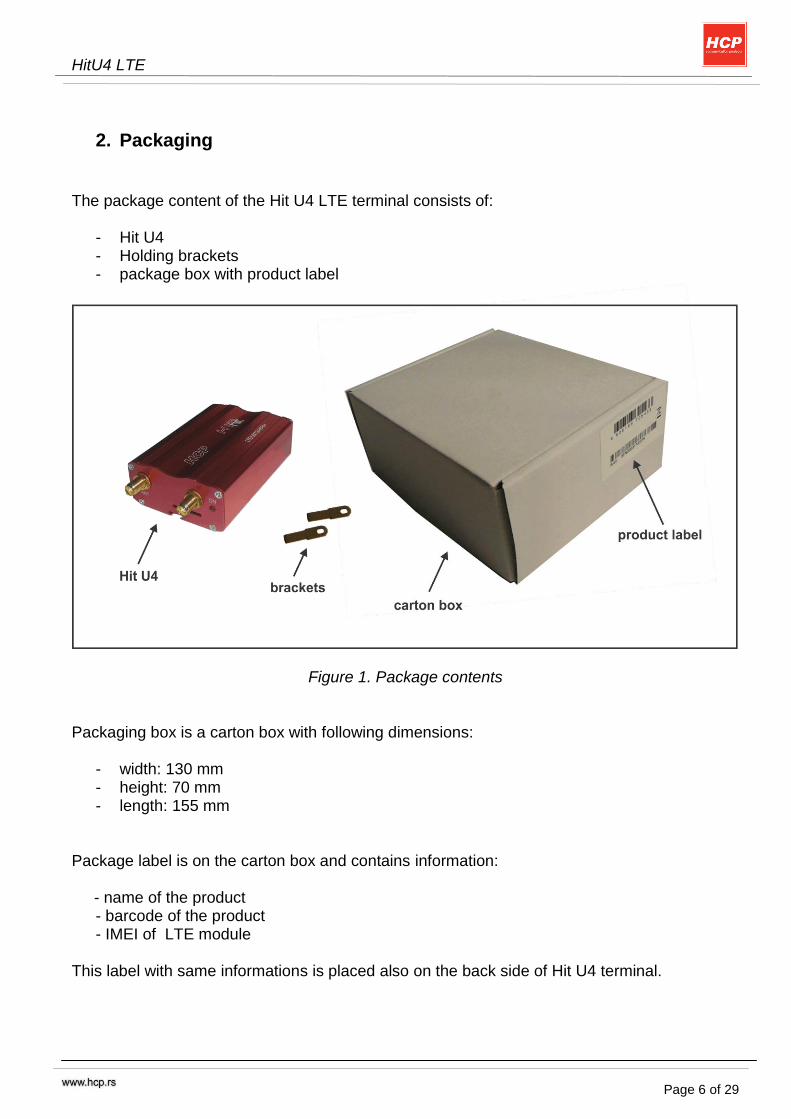
The package content of the Hit U4 LTE terminal consists of:
- Hit U4 - Holding brackets - package box with product label
Figure 1. Package contents Packaging box is a carton box with following dimensions:
- width: 130 mm - height: 70 mm - length: 155 mm
Package label is on the carton box and contains information: - name of the product
- barcode of the product - IMEI of LTE module
This label with same informations is placed also on the back side of Hit U4 terminal.
HitU4 LTE
Page 7 of 29
3. Key features
Feature Implementation
General
Incorporates Cinterion PLS8-E module
The PLS8-E module handles all processing for signal and data within the Hit U4 Terminal.
Frequency bands GSM/GPRS/EDGE: Dual band, 900/1800MHz UMTS/HSPA+: Triple band, 900 (BdVIII) / 1800 (BdIII) / 2100MHz (BdI) LTE: Five band, 800 (Bd20) / 900 (Bd8) / 1800 (Bd3) / 2100 (Bd1) / 2600MHz (Bd7)
GSM class Small MS
Output power (according to Release 99)
Class 4 (+33dBm ±2dB) for EGSM900 Class 1 (+30dBm ±2dB) for GSM1800 Class E2 (+27dBm ± 3dB) for GSM 900 8-PSK Class E2 (+26dBm +3 /-4dB) for GSM 1800 8-PSK Class 3 (+24dBm +1/-3dB) for UMTS 2100, WCDMA FDD BdI Class 3 (+24dBm +1/-3dB) for UMTS 1800, WCDMA FDD BdIII Class 3 (+24dBm +1/-3dB) for UMTS 900, WCDMA FDD BdVIII
Output power (according to Release 8)
Class 3 (+23dBm +-2dB) for LTE 2600, LTE FDD Bd7 Class 3 (+23dBm +-2dB) for LTE 2100, LTE FDD Bd1 Class 3 (+23dBm +-2dB) for LTE 1800, LTE FDD Bd3 Class 3 (+23dBm +-2dB) for LTE 900, LTE FDD Bd8 Class 3 (+23dBm +-2dB) for LTE 800, LTE FDD Bd20
Power supply Single supply voltage 8V to 24V DC
Operating temperature Normal operation: -30°C to +80°C
Physical Dimensions: 78mm x 54 x 26mm Weight: approx. 100 g
RoHS All hardware components fully compliant with EU RoHS Directive
LTE features
3GPP Release 9 UE CAT 3 supported DL 100Mbps, UL 50Mbps 2x2 MIMO in DL direction
HSPA features
3GPP Release 8 UE CAT. 14, 24 DC-HSPA+ – DL 42Mbps HSUPA – UL 5.76Mbps Compressed mode (CM) supported according to 3GPP TS25.212
UMTS features
3GPP Release 8 PS data rate – 384 kbps DL / 384 kbps UL
HitU4 LTE
Page 8 of 29
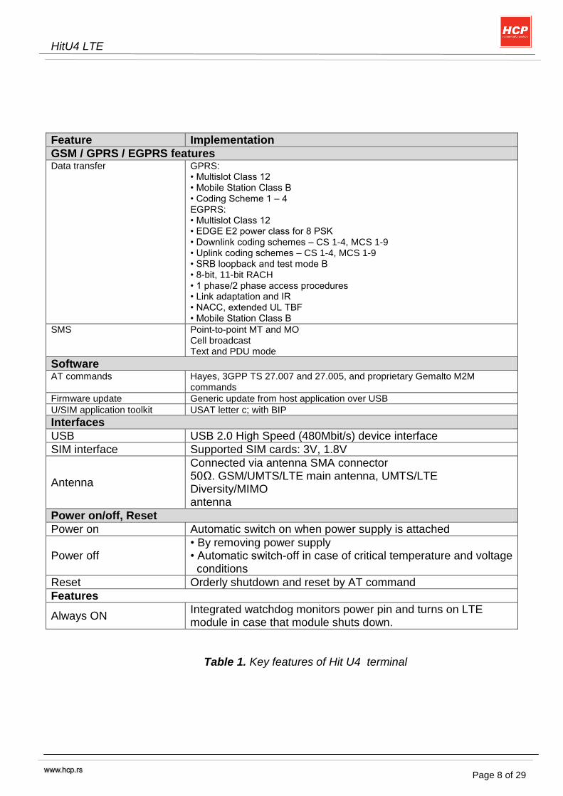
Feature Implementation
GSM / GPRS / EGPRS features Data transfer GPRS:
• Multislot Class 12 • Mobile Station Class B • Coding Scheme 1 – 4 EGPRS: • Multislot Class 12 • EDGE E2 power class for 8 PSK • Downlink coding schemes – CS 1-4, MCS 1-9 • Uplink coding schemes – CS 1-4, MCS 1-9 • SRB loopback and test mode B • 8-bit, 11-bit RACH • 1 phase/2 phase access procedures • Link adaptation and IR • NACC, extended UL TBF • Mobile Station Class B
SMS Point-to-point MT and MO Cell broadcast Text and PDU mode
Software AT commands Hayes, 3GPP TS 27.007 and 27.005, and proprietary Gemalto M2M
commands Firmware update Generic update from host application over USB U/SIM application toolkit USAT letter c; with BIP Interfaces
USB USB 2.0 High Speed (480Mbit/s) device interface
SIM interface Supported SIM cards: 3V, 1.8V
Antenna
Connected via antenna SMA connector 50Ω. GSM/UMTS/LTE main antenna, UMTS/LTE Diversity/MIMO antenna
Power on/off, Reset
Power on Automatic switch on when power supply is attached
Power off • By removing power supply • Automatic switch-off in case of critical temperature and voltage conditions
Reset Orderly shutdown and reset by AT command
Features
Always ON Integrated watchdog monitors power pin and turns on LTE module in case that module shuts down.
Table 1. Key features of Hit U4 terminal
HitU4 LTE
Page 9 of 29
4. Interface Description
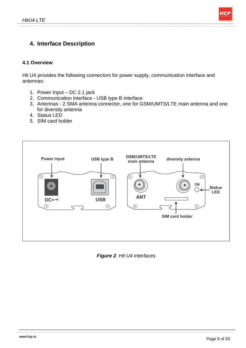
4.1 Overview
Hit U4 provides the following connectors for power supply, communication interface and antennas:
1. Power Input – DC 2.1 jack 2. Communication interface - USB type B interface 3. Antennas - 2 SMA antenna connector, one for GSM/UMTS/LTE main antenna and one
for diversity antenna 4. Status LED 5. SIM card holder
Figure 2. Hit U4 interfaces
HitU4 LTE
Page 10 of 29
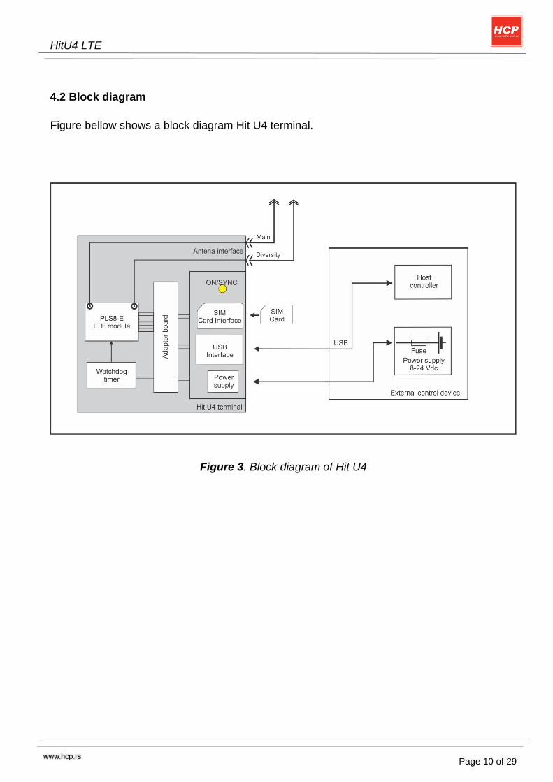
4.2 Block diagram
Figure bellow shows a block diagram Hit U4 terminal.
Figure 3. Block diagram of Hit U4

HitU4 LTE
Page 11 of 29
4.3 Operating Modes of GSM module in Hit U4
Mode Function
Normal operation GSM / GPRS / UMTS / HSPA / LTE SLEEP
Power saving set automatically when no call is in progress and the USB connection is detached.
GSM / GPRS / UMTS / HSPA / LTE IDLE
Power saving disabled or an USB connection active, but no data transfer in progress.
GPRS DATA GPRS data transfer in progress. Power consumption depends on network settings (e.g. power control level), uplink / downlink data rates and GPRS configuration (e.g. used multislot settings).
EGPRS DATA EGPRS data transfer in progress. Power consumption depends on network settings (e.g. power control level), uplink / downlink data rates and EGPRS configuration (e.g. used multislot settings).
UMTS DATA UMTS data transfer in progress. Power consumption depends on network settings (e.g. TPC Pattern) and data transfer rate.
HSPA DATA HSPA data transfer in progress. Power consumption depends on network settings (e.g. TPC Pattern) and data transfer rate.
LTE DATA LTE data transfer in progress. Power consumption depends on network settings (e.g. TPC Pattern) and data transfer rate.
Airplane mode Airplane mode shuts down the radio part of the module, causes the module to log off from the GSM/GPRS network and disables all AT commands whose execution requires a radio connection. Airplane mode can be controlled by AT command (see [1]).
Table 2. Operating modem of PLS8-E module
For more information about operating modes of PLS8-E module please refer to [1] and [2].
HitU4 LTE
Page 12 of 29
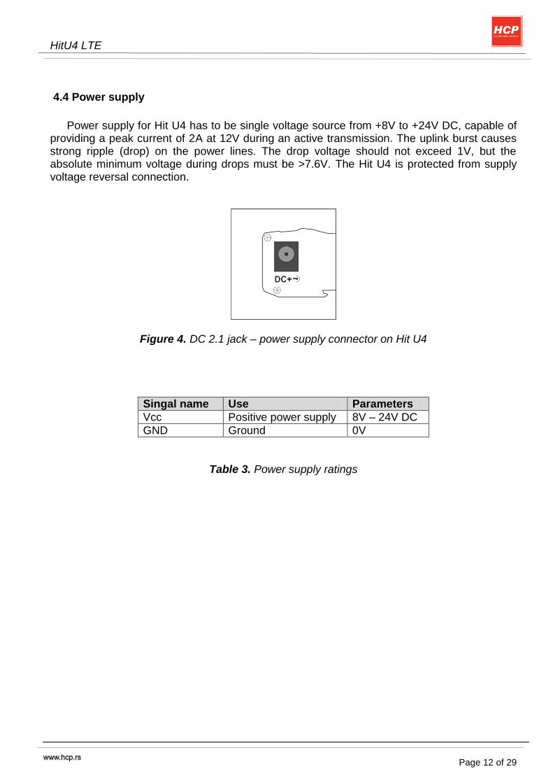
4.4 Power supply
Power supply for Hit U4 has to be single voltage source from +8V to +24V DC, capable of
providing a peak current of 2A at 12V during an active transmission. The uplink burst causes strong ripple (drop) on the power lines. The drop voltage should not exceed 1V, but the absolute minimum voltage during drops must be >7.6V. The Hit U4 is protected from supply voltage reversal connection.
Figure 4. DC 2.1 jack – power supply connector on Hit U4
Singal name Use Parameters
Vcc Positive power supply 8V – 24V DC
GND Ground 0V
Table 3. Power supply ratings
HitU4 LTE
Page 13 of 29
4.5 Turn on
Hit U4 switches on automatically when power supply is attached. After start-up, the
LTE module enters the net searching state.
Hit U4 has integrated hardware watchdog circuit which controls turn on state of LTE module.For detailed info about watchdog look on the next page. 4.6 Turn off Turn off state of the LTE module is controlled by the watchdog mode. Please look watchdog mode info regarding turn on/turn off.
4.6 Automatic shutdown
Automatic shutdown takes effect if: - The PLS8-E module board is exceeding the critical limits of overtemperature or undertemperature - Undervoltage or overvoltage is detected
The automatic shutdown procedure is equivalent to the power down initiated with the AT^SMSO command, i.e. PLS8-E logs off from the network and the software enters a secure state avoiding loss of data.
Alert messages transmitted before the device switches off are implemented as Unsolicited Result Codes (URCs). The presentation of the temperature URCs can be enabled or disabled with the AT commands AT^SCTM.. For further instructions on AT commands refer to [1].
HitU4 LTE
Page 14 of 29
4.7 Watchdog
Hit U4 has integrated hardware watchdog circuit for ignition control and LTE module
power on monitoring. After power is supplied to Hit U4, ignition impulse is send to LTE module, if LTE module
doesn‟t turn on after few seconds when power supply is attached, watchdog circuit continues to send ignition impulses until LTE module is turned on.
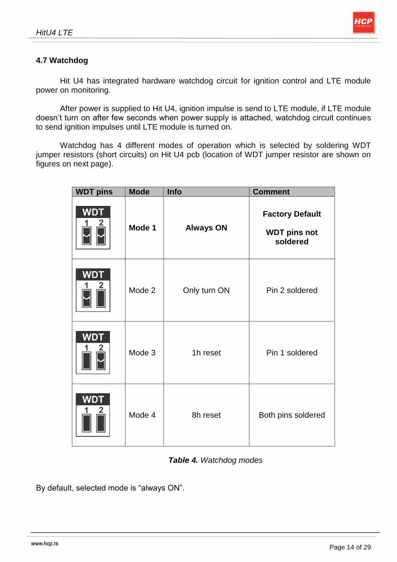
Watchdog has 4 different modes of operation which is selected by soldering WDT
jumper resistors (short circuits) on Hit U4 pcb (location of WDT jumper resistor are shown on figures on next page).
WDT pins Mode Info Comment
Mode 1 Always ON
Factory Default
WDT pins not soldered
Mode 2 Only turn ON Pin 2 soldered
Mode 3 1h reset Pin 1 soldered
Mode 4 8h reset Both pins soldered
Table 4. Watchdog modes
By default, selected mode is “always ON”.
HitU4 LTE
Page 15 of 29
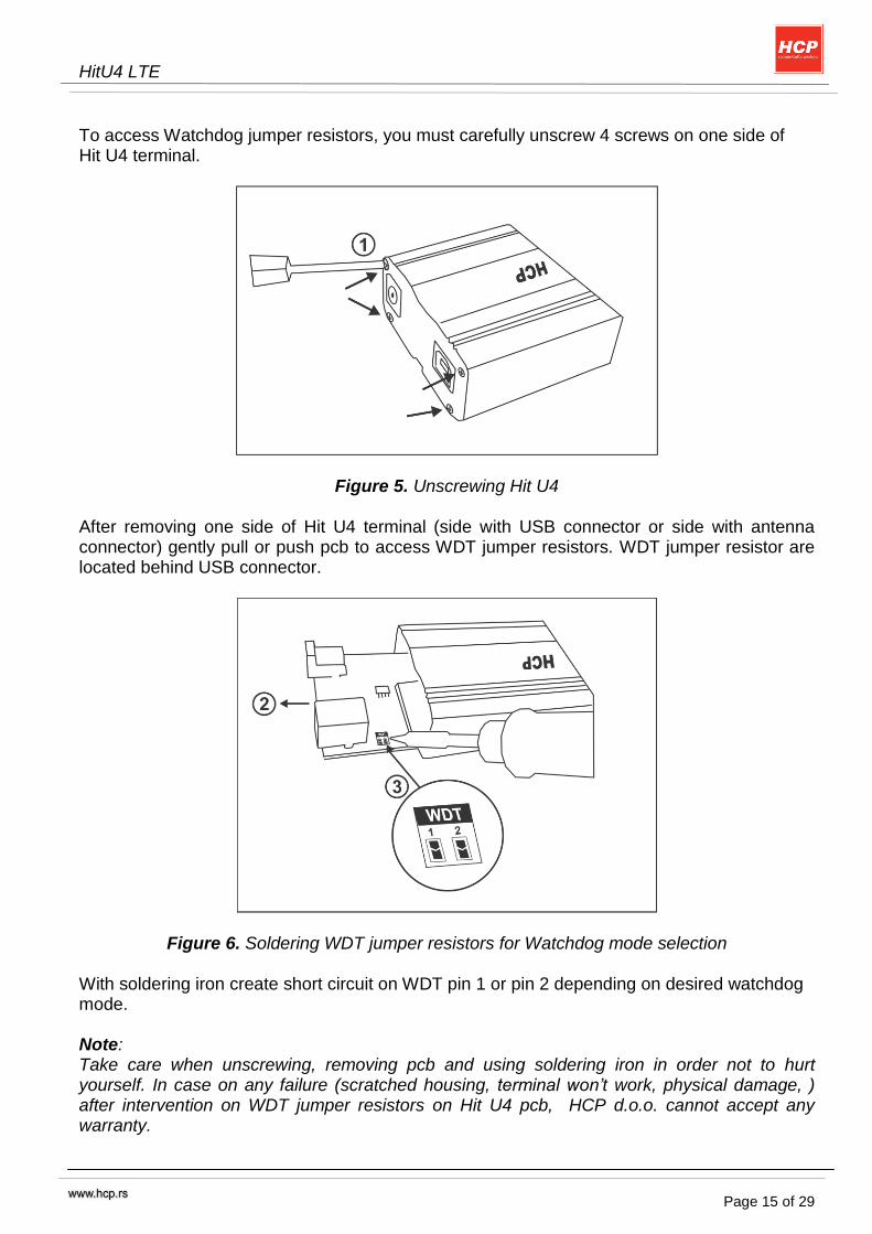
To access Watchdog jumper resistors, you must carefully unscrew 4 screws on one side of Hit U4 terminal.
Figure 5. Unscrewing Hit U4
After removing one side of Hit U4 terminal (side with USB connector or side with antenna connector) gently pull or push pcb to access WDT jumper resistors. WDT jumper resistor are located behind USB connector.
Figure 6. Soldering WDT jumper resistors for Watchdog mode selection
With soldering iron create short circuit on WDT pin 1 or pin 2 depending on desired watchdog mode. Note: Take care when unscrewing, removing pcb and using soldering iron in order not to hurt yourself. In case on any failure (scratched housing, terminal won’t work, physical damage, ) after intervention on WDT jumper resistors on Hit U4 pcb, HCP d.o.o. cannot accept any warranty.

HitU4 LTE
Page 16 of 29
4.7.1. Mode 1 – Always ON
Watchdog circuit monitors LTE module “power on” line, if LTE module shuts down (power supply failure, over or under temperature …) watchdog circuit will send ignition impulses until LTE module is turned on. To shut down LTE module, you must disconnect power supply. If you try to turn of module by at command AT^ SMSO, watchdog will detect that module is turned off and it will turn it on after few seconds.
4.7.2. Mode 2 – One time turn on
After power up, Watchdog checks is LTE module turned on, if the module is turned on, watchdog have no function. If, after power up LTE module is not turned on, watchdog will send ignition impulses until module is turned on, when it detects that module is turned on, watchdog have no function. To shut down LTE module in this mode, you can do it:
- by disconnecting power supply. - By sending AT command AT^ SMSO
If module is turned off by AT command and power supply is not removed, in order to turn it on again you can do it by: - unplug/plug USB connector - disconnect/connect power supply
4.7.3. Mode 3 – 1h reset
After power up, Watchdog checks is LTE module turned on, if it is, it starts 1h timer and when 1h time elapses, watchdog resets LTE module ( shuts down LTE module with EMERG_OFF line, and turns it on again). In 1h timer, watchdog checks every ~30s is module on, if module gets shutdown, watchdog circuit will perform ignition sequence. If module is turned off by AT command or there were power failure, watchdog will try to turn it on again.
4.7.4. Mode 4 – 8h reset
After power up, Watchdog checks is LTE module turned on, if it is, it starts 8h timer and when ~8h time elapses, watchdog resets LTE module ( shuts down LTE module with EMERG_OFF line, and turns it on again). In 8h timer, watchdog checks every ~30s is module on, if module gets shutdown, watchdog circuit will perform ignition sequence. If module is turned off by AT command or there were power failure, watchdog will try to turn it on again.
HitU4 LTE
Page 17 of 29
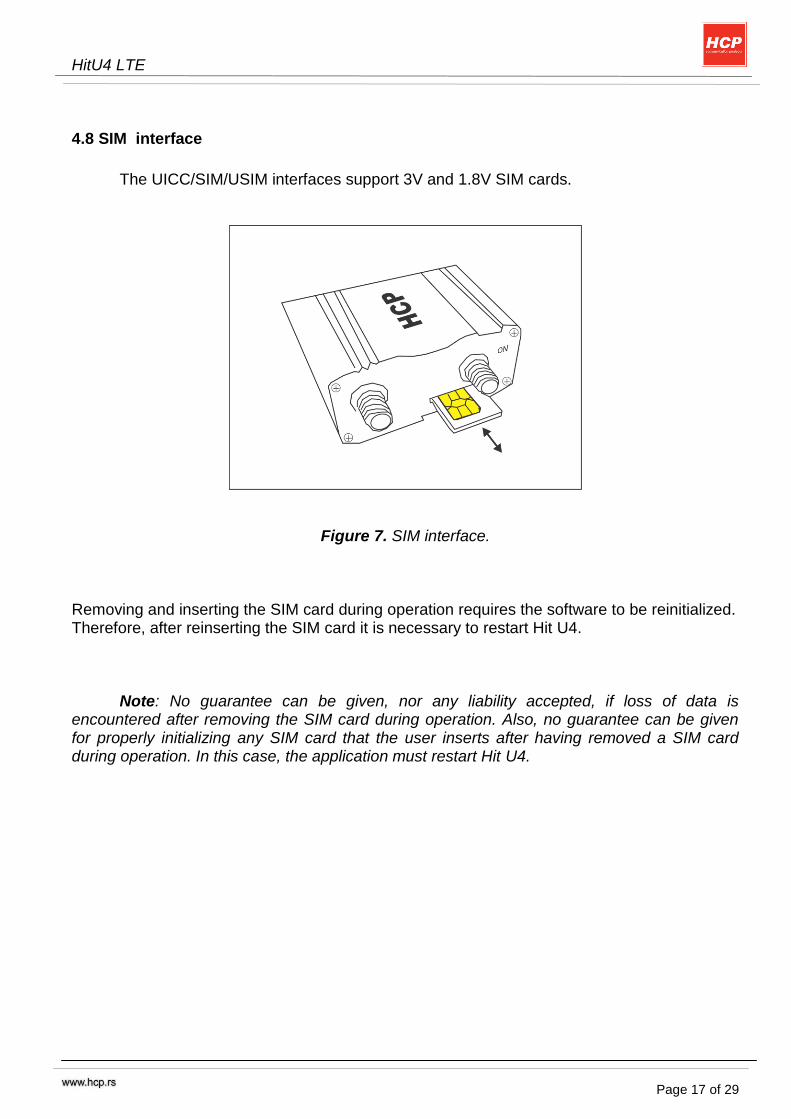
4.8 SIM interface
The UICC/SIM/USIM interfaces support 3V and 1.8V SIM cards.
Figure 7. SIM interface. Removing and inserting the SIM card during operation requires the software to be reinitialized. Therefore, after reinserting the SIM card it is necessary to restart Hit U4.
Note: No guarantee can be given, nor any liability accepted, if loss of data is encountered after removing the SIM card during operation. Also, no guarantee can be given for properly initializing any SIM card that the user inserts after having removed a SIM card during operation. In this case, the application must restart Hit U4.
HitU4 LTE
Page 18 of 29
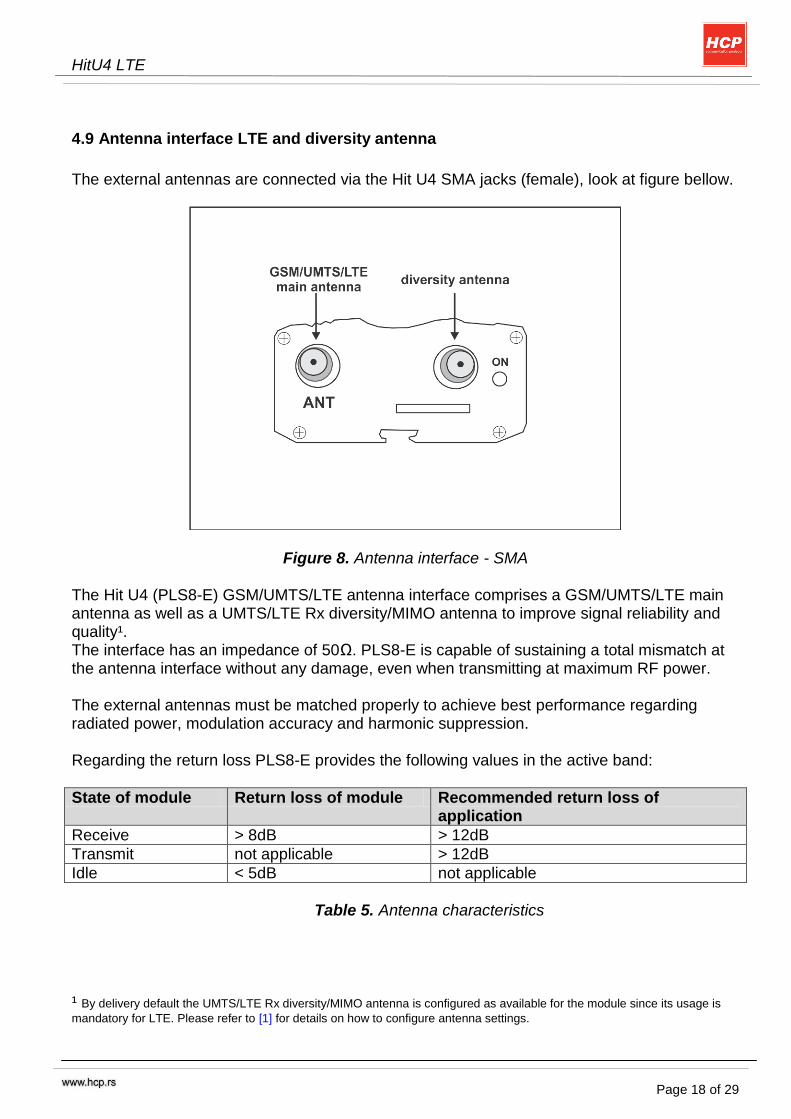
4.9 Antenna interface LTE and diversity antenna
The external antennas are connected via the Hit U4 SMA jacks (female), look at figure bellow.
Figure 8. Antenna interface - SMA The Hit U4 (PLS8-E) GSM/UMTS/LTE antenna interface comprises a GSM/UMTS/LTE main antenna as well as a UMTS/LTE Rx diversity/MIMO antenna to improve signal reliability and quality¹. The interface has an impedance of 50Ω. PLS8-E is capable of sustaining a total mismatch at the antenna interface without any damage, even when transmitting at maximum RF power. The external antennas must be matched properly to achieve best performance regarding radiated power, modulation accuracy and harmonic suppression. Regarding the return loss PLS8-E provides the following values in the active band:
State of module Return loss of module Recommended return loss of application
Receive > 8dB > 12dB
Transmit not applicable > 12dB
Idle < 5dB not applicable
Table 5. Antenna characteristics
¹ By delivery default the UMTS/LTE Rx diversity/MIMO antenna is configured as available for the module since its usage is
mandatory for LTE. Please refer to [1] for details on how to configure antenna settings.

HitU4 LTE
Page 19 of 29
4.10 Status LED
Figure 10. Status LED
PLS8-E Status <mode>=1 <mode>=2 <flash>= default
<mode>=2 <flash>= user defined <mode>=3
- GSM voice call in progress or established - UMTS voice call in progress or established
Permanently on
10 ms on / 990 ms off
on + off (interval) = 1000 ms
(fixed) <flash> *
1000) / 1000) ms (variable)
- GSM PS data transfer - UMTS/LTE data transfer Permanently
on 10 ms on /
1990 ms off
on + off (interval) = 2000 ms
<flash> *
2000) / 1000)
UE registered to a network. No call, no data transfer
Permanently on
10 ms on / 3990 ms off
on + off (interval) = 4000 ms
<flash> *
4000) / 1000) ms (variable)
Limited Network Service (e.g. because no SIM/ USIM, no PIN or during network search)
500 ms on / 500 ms off
500 ms on/ 500 ms off
on + off (interval) = 1000 ms
- UMTS/LTE operation mode Permanently on
- GSM operation mode Permanently on
Table 6. Status LED behavior
HitU4 LTE
Page 20 of 29
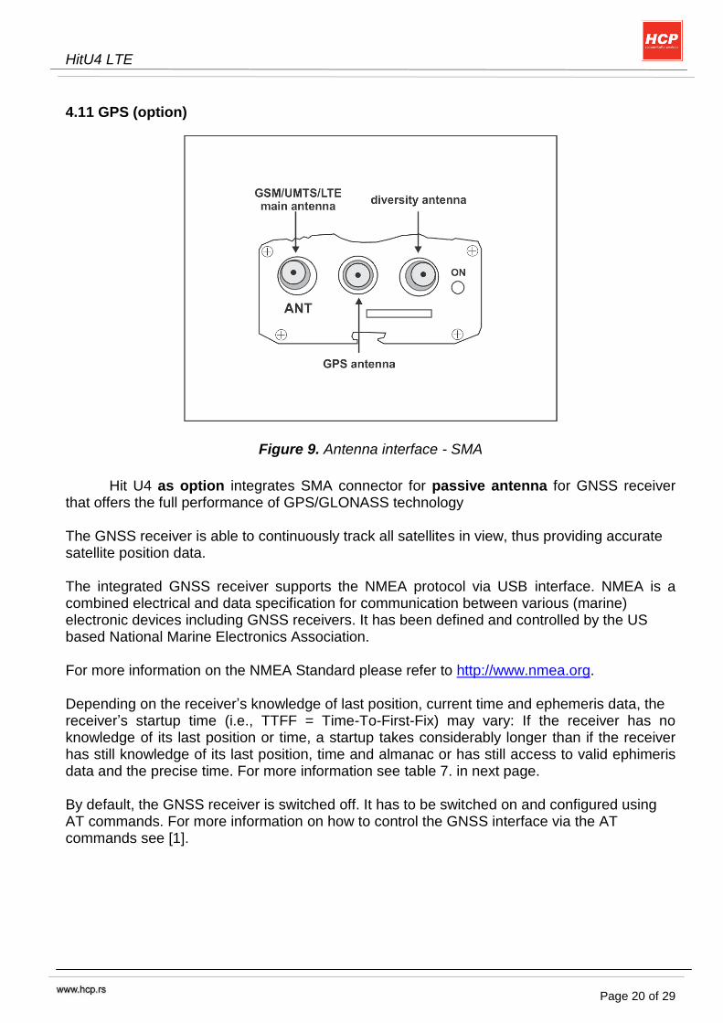
4.11 GPS (option)
Figure 9. Antenna interface - SMA
Hit U4 as option integrates SMA connector for passive antenna for GNSS receiver
that offers the full performance of GPS/GLONASS technology The GNSS receiver is able to continuously track all satellites in view, thus providing accurate satellite position data. The integrated GNSS receiver supports the NMEA protocol via USB interface. NMEA is a combined electrical and data specification for communication between various (marine) electronic devices including GNSS receivers. It has been defined and controlled by the US based National Marine Electronics Association. For more information on the NMEA Standard please refer to http://www.nmea.org. Depending on the receiver‟s knowledge of last position, current time and ephemeris data, the receiver‟s startup time (i.e., TTFF = Time-To-First-Fix) may vary: If the receiver has no knowledge of its last position or time, a startup takes considerably longer than if the receiver has still knowledge of its last position, time and almanac or has still access to valid ephimeris data and the precise time. For more information see table 7. in next page. By default, the GNSS receiver is switched off. It has to be switched on and configured using AT commands. For more information on how to control the GNSS interface via the AT commands see [1].

HitU4 LTE
Page 21 of 29
The following tables list general characteristics of the GNSS interface.
Parameter Conditions Min. Typical Max. Unit
Frequency GPS GLONASS
1597.551
1575.42 1605.886
MHz
Tracking Sensitivity
Open sky Passive antenna
-156
dBm
Acquisition Sensitivity
Open sky Passive antenna
-145
dBm
Cold Start
sensitivity¹
-145 dBm
Time-to-First-Fix (TTFF)2
Cold 25 32 s
Warm 10 29 s
Table 7. Recommended operating conditions ¹ Test condition: Assumes 300 seconds timeout, QoS=1000m, and 50% yield.
² Test condition: TTFF is defined for an open sky environment, i.e., with a clear view to the sky and a minimum signal level of -130dBm at the antenna for at least 3…4 satellites. This signal level represents C/No=42dB in an NMEA $GPGSV message.
HitU4 LTE
Page 22 of 29
5. Electrical and Environmental Characteristics
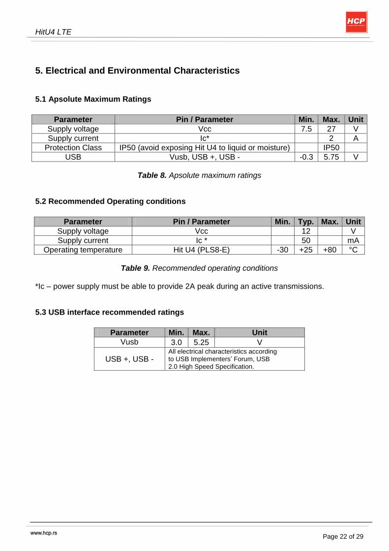
5.1 Apsolute Maximum Ratings
Parameter Pin / Parameter Min. Max. Unit
Supply voltage Vcc 7.5 27 V
Supply current Ic* 2 A
Protection Class IP50 (avoid exposing Hit U4 to liquid or moisture) IP50
USB Vusb, USB +, USB - -0.3 5.75 V
Table 8. Apsolute maximum ratings
5.2 Recommended Operating conditions
Parameter Pin / Parameter Min. Typ. Max. Unit
Supply voltage Vcc 12 V
Supply current Ic * 50 mA
Operating temperature Hit U4 (PLS8-E) -30 +25 +80 °C
Table 9. Recommended operating conditions
*Ic – power supply must be able to provide 2A peak during an active transmissions.
5.3 USB interface recommended ratings
Parameter Min. Max. Unit
Vusb 3.0 5.25 V
USB +, USB - All electrical characteristics according to USB Implementers‟ Forum, USB 2.0 High Speed Specification.
HitU4 LTE
Page 23 of 29
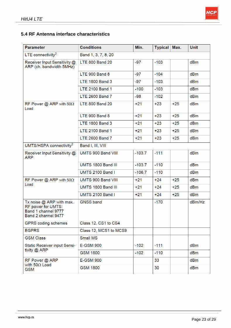
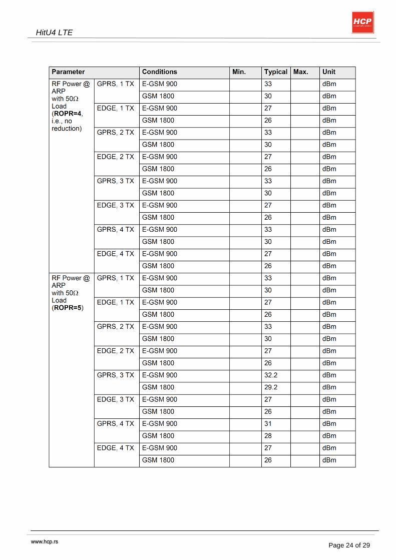
5.4 RF Antenna interface characteristics
HitU4 LTE
Page 24 of 29

HitU4 LTE
Page 25 of 29
HitU4 LTE
Page 26 of 29
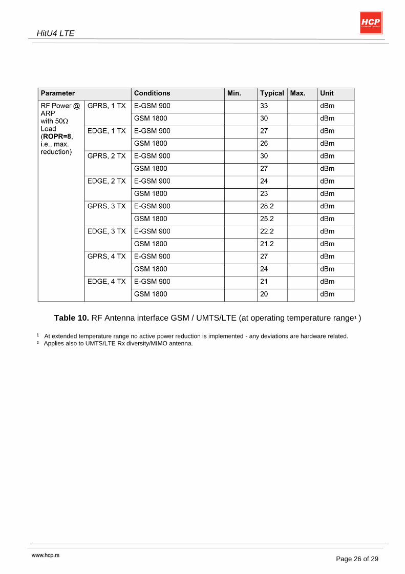
Table 10. RF Antenna interface GSM / UMTS/LTE (at operating temperature range¹ )
¹ At extended temperature range no active power reduction is implemented - any deviations are hardware related.
² Applies also to UMTS/LTE Rx diversity/MIMO antenna.
HitU4 LTE
Page 27 of 29
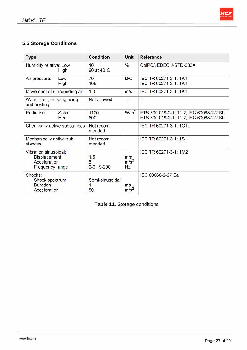
5.5 Storage Conditions
Table 11. Storage conditions
HitU4 LTE
Page 28 of 29
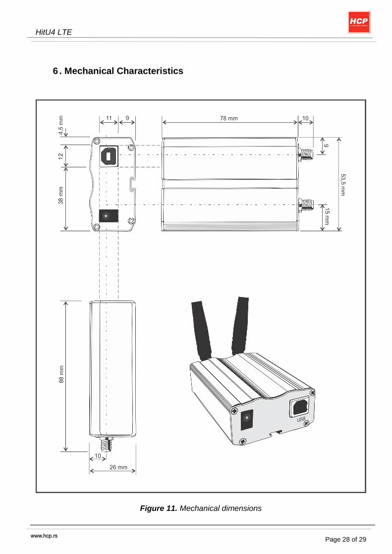
6 . Mechanical Characteristics
Figure 11. Mechanical dimensions
HitU4 LTE
Page 29 of 29
HCP d.o.o. Nake Spasic 1 11040 Beograd, SERBIA Phn. +381.37.445.401
+381.37.418.790 Fax. +381.37.448.351
Website www.hcp.rs
Sales email: [email protected] Support: [email protected] Development: [email protected]
![Ouray 400 Sistema [U4] Selux · U4-#2. U4-#3. U4-#4 U4-Fixture # Series Optics. Mounting Light. Options. Engine. Rivnut. Pairs RN Fixture # CCT Finish. Voltage *Refer to chart on](https://img.pdfslide.us/doc/110x75/5f94b53bcc58146dfa1c1ffc/ouray-400-sistema-u4-selux-u4-2-u4-3-u4-4-u4-fixture-series-optics-mounting.jpg)