Embed Size (px)
Citation preview
California MUTCD 2014 Edition (FHWA’s MUTCD 2009 Edition, including Revisions 1 & 2, as amended for use in California)
Chapter 9C – Markings November 7, 2014 Part 9 – Traffic Control for Bicycle Facilities
Page 1379
CHAPTER 9C. MARKINGS
Section 9C.01 Functions of Markings
Support: 01 Markings indicate the separation of the lanes for road users, assist the bicyclist by indicating assigned travel
paths, indicate correct position for traffic control signal actuation, and provide advance information for turning and crossing maneuvers.
Section 9C.02 General Principles
Guidance: 01 Bikeway design guides (see Section 9A.05) should be used when designing markings for bicycle facilities.
Standard: 02 Markings used on bikeways shall be retroreflectorized. 02a On State highways, markings material shall conform to Sections 84-2.02 and 84-3.02 of the Standard
Specifications published by Caltrans. Guidance:
03 Pavement marking word messages, symbols, and/or arrows should be used in bikeways where appropriate. Consideration should be given to selecting pavement marking materials that will minimize loss of traction for bicycles under wet conditions. Standard:
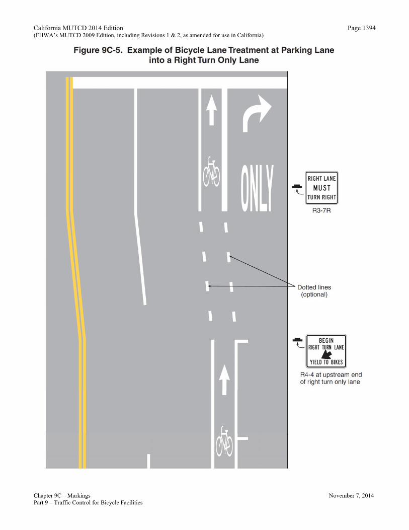
04 The colors, width of lines, patterns of lines, symbols, and arrows used for marking bicycle facilities shall be as defined in Sections 3A.05, 3A.06, and 3B.20. Support:
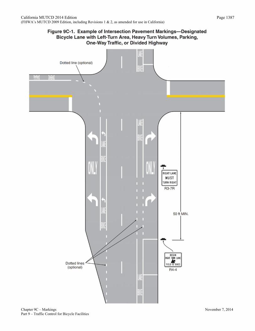
05 Figures 9B-7 and 9C-1 through 9C-9 show examples of the application of lines, word messages, symbols, and arrows on designated bikeways. Option:
06 A dotted line may be used to define a specific path for a bicyclist crossing an intersection (see Figure 9C-1) as described in Sections 3A.06 and 3B.08.
Section 9C.03 Marking Patterns and Colors on Shared-Use Paths
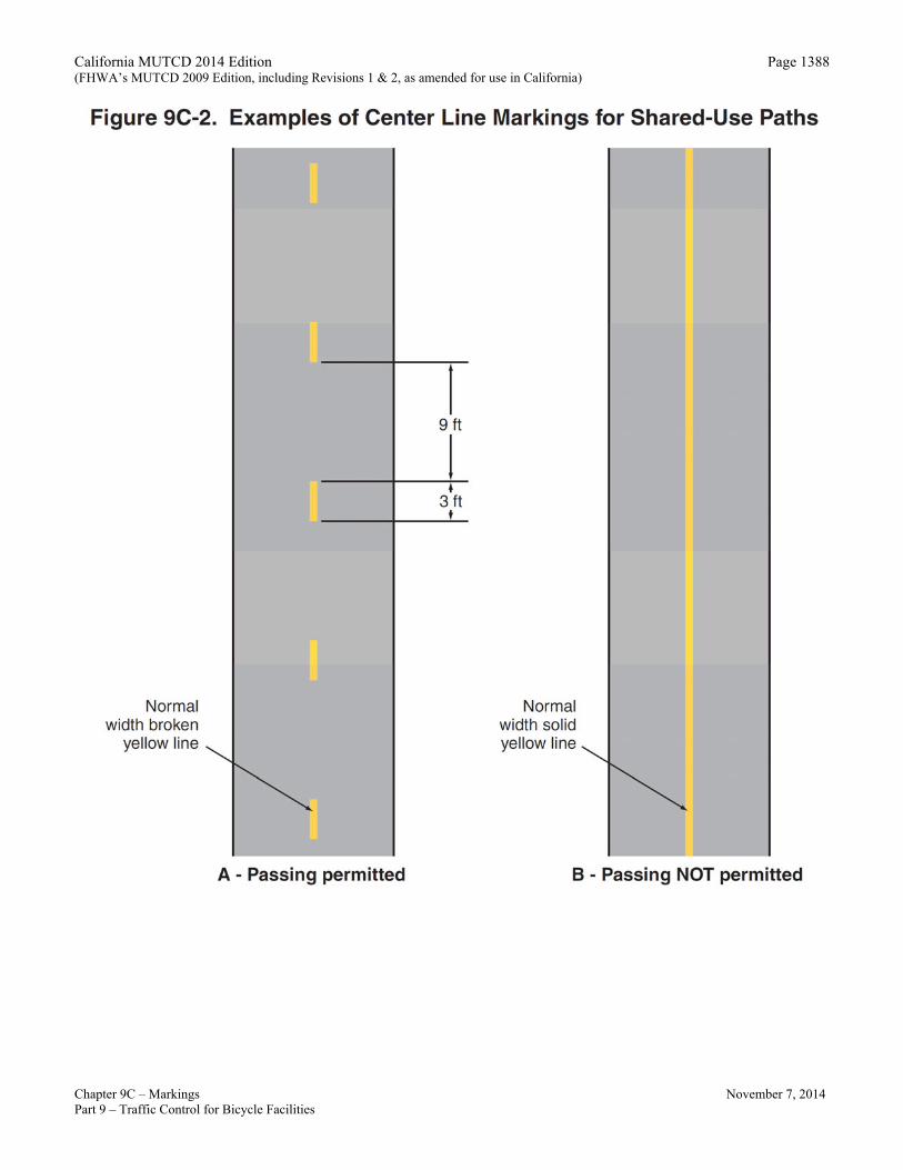
Option: 01 Where shared-use paths are of sufficient width to designate two minimum width lanes, a solid yellow line
may be used to separate the two directions of travel where passing is not permitted, and a broken yellow line may be used where passing is permitted (see Figure 9C-2). Guidance:
02 Broken lines used on shared-use paths should have the usual 1-to-3 segment-to-gap ratio. A nominal 3-foot segment with a 9-foot gap should be used.
03 If conditions make it desirable to separate two directions of travel on shared-use paths at particular locations, a solid yellow line should be used to indicate no passing and no traveling to the left of the line.
04 Markings as shown in Figure 9C-2 9C-8 should be used at the location of obstructions in the center of the path, including vertical elements intended to physically prevent unauthorized motor vehicles from entering the path. Support:
05 A centerline marking is particularly beneficial in the following circumstances: A. Where there is heavy use; B. On curves with restricted sight distance; and, C. Where the path is unlighted and nighttime riding is expected.
Option: 05 A solid white line may be used on shared-use paths to separate different types of users. The R9-7 sign (see
Section 9B.12) may be used to supplement the solid white line.
California MUTCD 2014 Edition (FHWA’s MUTCD 2009 Edition, including Revisions 1 & 2, as amended for use in California)
Chapter 9C – Markings November 7, 2014 Part 9 – Traffic Control for Bicycle Facilities
Page 1380
05a A solid white line may be used to delineate the traveled way of the bike path from the shoulder if the shoulder is paved with the same material as the bike path. Support: 05b Refer to Caltrans’ Highway Design Manual Index 1003.1. 06 Smaller size letters and symbols may be used on shared-use paths. Where arrows are needed on shared-use
paths, half-size layouts of the arrows may be used (see Section 3B.20). Section 9C.04 Markings For Bicycle Lanes
Support: 01 Pavement markings designate that portion of the roadway for preferential use by bicyclists. Markings inform
all road users of the restricted nature of the bicycle lane. Standard:
02 Longitudinal pavement markings shall be used to define bicycle lanes. Guidance:
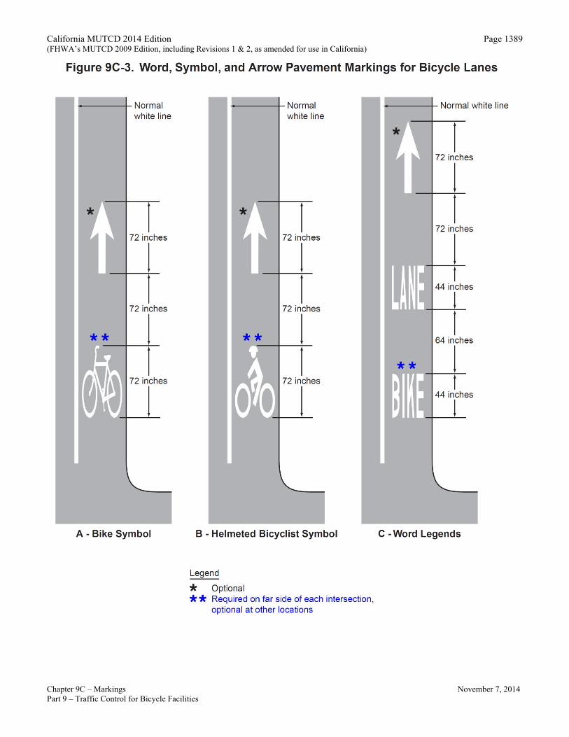
03 If used, bicycle lane word, symbol, and/or arrow markings (see Figure 9C-3) should be placed at the beginning of a bicycle lane and at periodic intervals along the bicycle lane based on engineering judgment. Standard:
04 If the bicycle lane symbol marking is used in conjunction with word or arrow messages, it shall precede them. Option:
05 If the word, symbol, and/or arrow pavement markings shown in Figure 9C-3 are used, Bike Lane signs (see Section 9B.04) may also be used, but to avoid overuse of the signs not necessarily adjacent to every set of pavement markings. Bicycle Lane Treatment at Intersections Option:
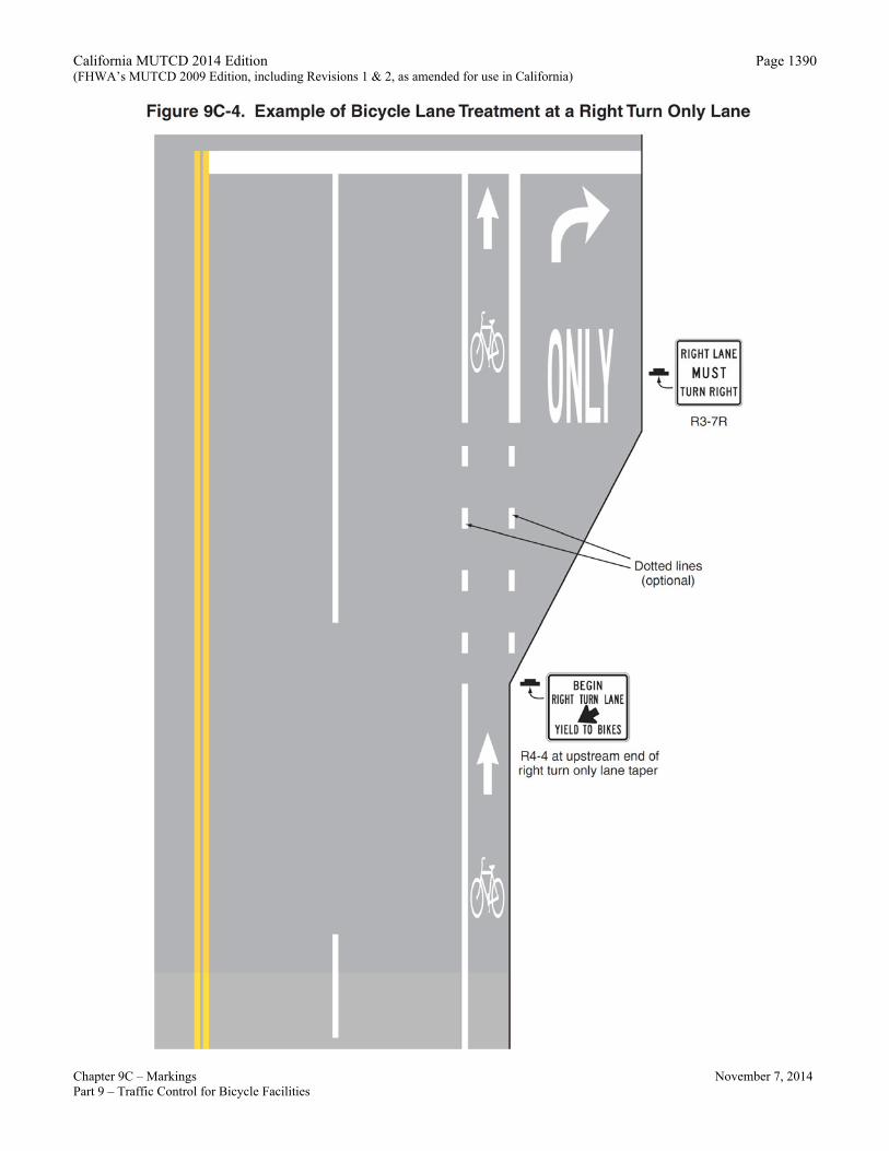
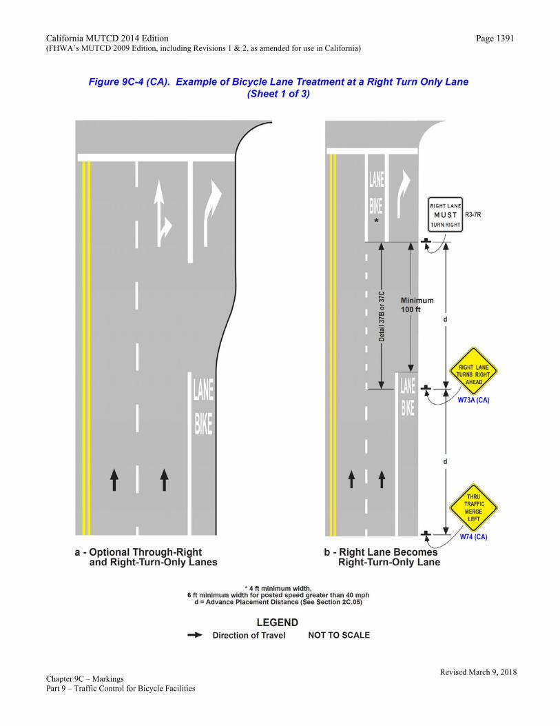
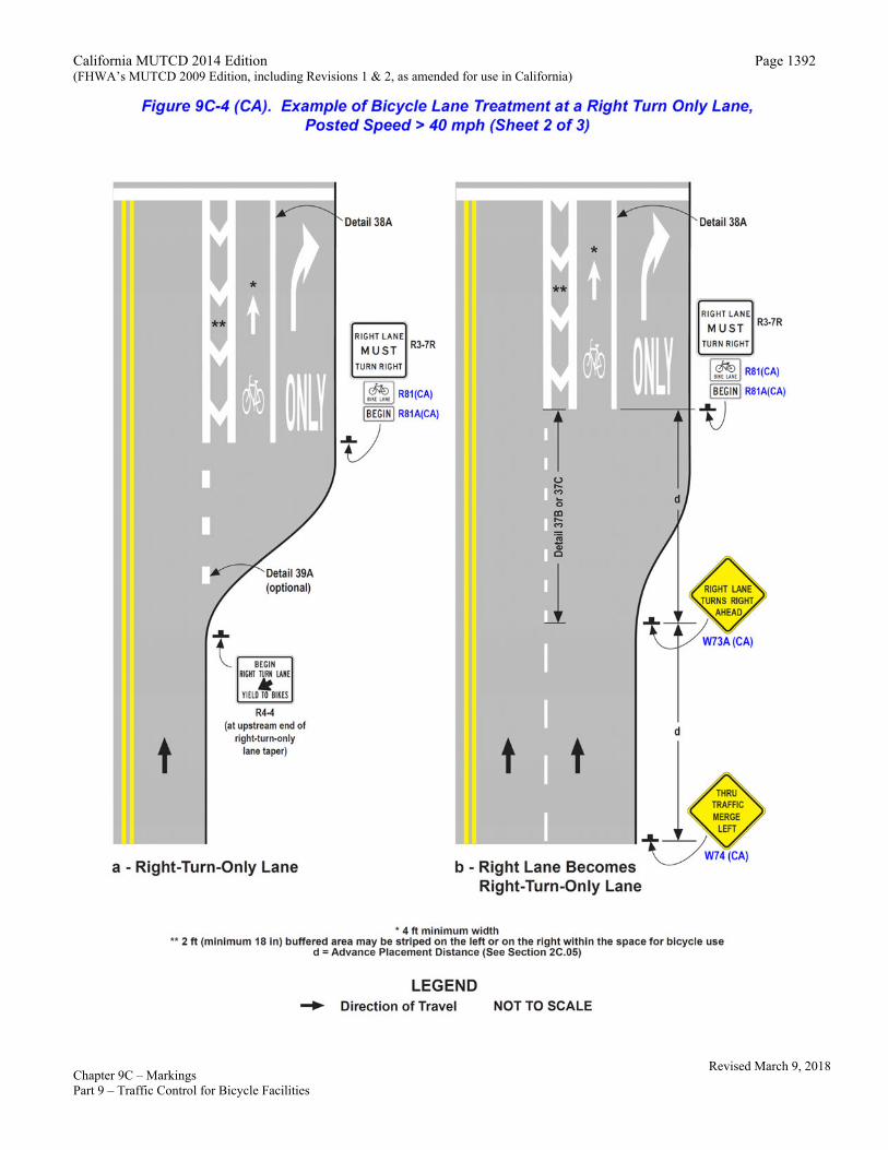
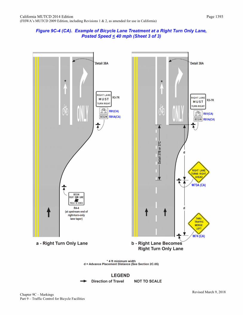
05a When a bike lane approaches an intersection with right- or left-turn only lanes, Figures 9C-1, 9C-4, 9C-4(CA) or 9C-5 may be used. Standard:
06 A through bicycle lane shall not be positioned to the right of a right turn only lane or to the left of a left turn only lane. Support:
07 A bicyclist continuing straight through an intersection from the right of a right-turn lane or from the left of a left-turn lane would be inconsistent with normal traffic behavior and would violate the expectations of right- or left-turning motorists. Guidance:
08 When the right through lane is dropped to become a right turn only lane, the bicycle lane markings should stop at least 100 feet before the beginning of the right-turn lane. Through bicycle lane markings should resume to the left of the right turn only lane.
09 An optional through-right turn lane next to a right turn only lane should not be used where there is a through bicycle lane. If a capacity analysis indicates the need for an optional through-right turn lane, the bicycle lane should be discontinued at the intersection approach.
09a A dashed line across the right-turn-only lane should not be used on extremely long lanes, or where there are double right-turn-only lanes. For these types of intersections, all striping should be dropped to permit judgment by the bicyclists to prevail. Option:
09b A Bicycle Crossing (W11-1) sign may be used to warn road users of the potential for bicyclists crossing their path. See Section 9B.18.
09c When a bike lane approaches ramp intersection that intersects the local facility at or close to 90° (typical of a compact or spread diamond configuration), then Figures 9C-4, 9C-4(CA) and 9C-5 may be used. Guidance:
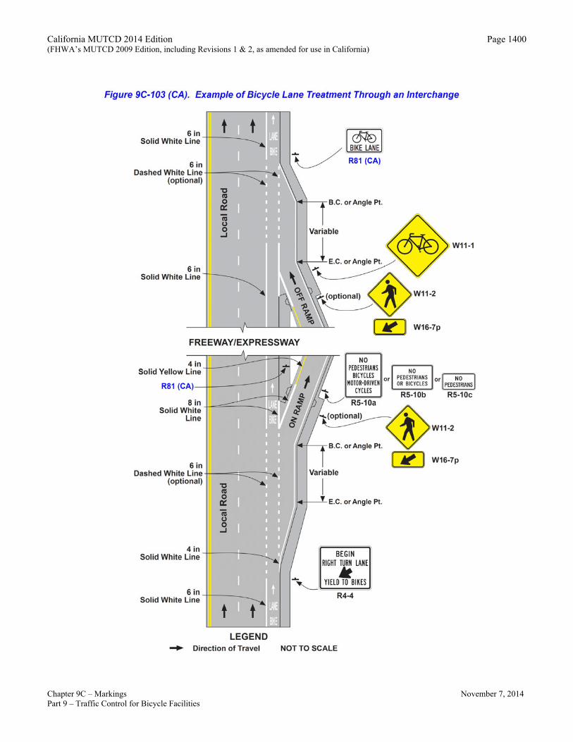
09d However, when a bike lane approaches one or more ramp intersections that intersect the local facility at various angles other than 90° (typically high-speed, skewed ramps), Figure 9C-103(CA) should be used.
Revised March 9, 2018
California MUTCD 2014 Edition (FHWA’s MUTCD 2009 Edition, including Revisions 1 & 2, as amended for use in California)
Chapter 9C – Markings November 7, 2014 Part 9 – Traffic Control for Bicycle Facilities
Page 1381
Option: 09e At locations with right-turn-only lanes where bicycles are not prohibited but Class II bicycle facilities do not exist on the
approach, a minimum 4-foot wide space for bicycle use may be provided between the right-turn and through lane, and where the posted speed is greater than 40 mph the minimum width should be 6 feet.
09f When the width between the right-turn and through lane is greater than 4-feet, a buffer area may be striped adjacent to the 4’ minimum width for bicycle travel, regardless of the posted speed.
09g The buffer may be placed on the left or on the right of the 4’ space for bicycle travel. Support: 09h Refer to Caltrans’ Highway Design Manual, Index 403.6.
Standard: 09i If used, the space for bicycle use shall be delineated by Detail 39 on the right of the through lane and Detail 38A
on the left of the right-turn-only lane. Support: 09j Refer to Figure 9C-4(CA) for details on striping and Figure 9C-104 (CA) for details on buffer area striping.
Guidance: 10 Posts or raised pavement markers should not be used to separate bicycle lanes from adjacent travel lanes.
Support: 11 Using raised devices creates a collision potential for bicyclists by placing fixed objects immediately adjacent
to the travel path of the bicyclist. In addition, raised devices can prevent vehicles turning right from merging with the bicycle lane, which is the preferred method for making the right turn. Raised devices used to define a bicycle lane can also cause problems in cleaning and maintaining the bicycle lane. Option:
11a A bicycle lane for travel in the same direction as the general purpose lanes may be placed on the left hand side of the general purpose lanes. Standard:
12 Bicycle lanes shall not be provided on the circular roadway of a roundabout. Guidance:
13 Bicycle lane markings should stop at least 100 feet before the crosswalk, or if no crosswalk is provided, at least 100 feet before the yield line, or if no yield line is provided, then at least 100 feet before the edge of the circulatory roadway. Support:
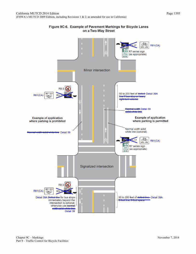
14 Examples of bicycle lane markings at right-turn lanes are shown in Figures 9C-1, 9C-4, and 9C-5. Examples of pavement markings for bicycle lanes on a two-way street are shown in Figure 9C-6. Pavement word message, symbol, and arrow markings for bicycle lanes are shown in Figure 9C-3.
15 Class III Bikeways (Bike Route) are shared routes and do not require pavement markings. In some instances, a 4 inch white edge stripe separating the traffic lanes from the shoulder can be helpful in providing for safer shared use. This practice is particularly applicable on rural highways and on major arterials in urban areas where there is no vehicle parking. Option:
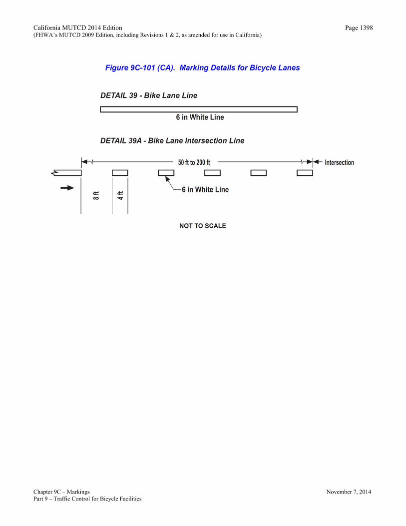
16 The Bike Lane Intersection (Detail 39A) line as shown in Figure 9C-101(CA) may be used to extend the bike lane to or through an intersection.
Bicycle Lane Markings on Class II Bikeways (Bike Lane) Guidance:
17 Bicycle lane markings on Class II Bikeways (Bike Lane) should be placed a constant distance from the marked lane line or centerline, as appropriate. Bike lanes with parking permitted should not be directed toward the curb at intersections or localized areas where parking is prohibited. Such a practice prevents bicyclists from following a straight course. Where transitions from one type of bike lane to another are necessary, smooth tapers should be provided. Support:
18 Class II Bikeways (Bike Lane) require standard signing and pavement markings as shown in Figure 9C-102(CA). This figure also depicts the proper method of striping bike lanes through intersections. Bike lane lines are not typically extended through intersections. Guidance:
19 Where right turns are not permitted, the solid bike lane stripe should extend to the edge of the intersection, and begin
Revised March 9, 2018
California MUTCD 2014 Edition (FHWA’s MUTCD 2009 Edition, including Revisions 1 & 2, as amended for use in California)
Chapter 9C – Markings November 7, 2014 Part 9 – Traffic Control for Bicycle Facilities
Page 1382
again on the far side. Where there is no right turn only lane and right turns are permitted, the solid stripe should terminate 50 feet to 200 feet prior to the intersection. Option:
20 A dashed line, as shown in Figure 9C-102(CA), may be carried to, or near, the intersection. Where city blocks are short (less than 400 feet), the length of dashed stripe may be 50 feet. Guidance:
21 Where blocks are longer or vehicle speeds are high (greater than 35 mph), the length of dashed stripe should be increased to 200 feet. Standard:
22 Raised barriers (e.g., raised traffic bars and asphalt concrete dikes) or raised pavement markers shall not be used to delineate bike lanes on Class II Bikeways (Bike Lane). Support:
23 Raised barriers prevent motorists from merging into bike lanes before making right turns, as required by the CVC, and restrict the movement of bicyclists desiring to enter or exit bike lanes.
24 They also impede routine maintenance. Raised pavement markers increase the difficulty for bicyclists when entering or exiting bike lanes, and discourage motorists from merging into bike lanes before making right turns. Option:
25 Physical barriers may be used to convert a Class II Bikeway (Bike Lane) to Class I Bikeway (Bike Path) or Class IV Bikeway (Separated Bikeway).
Bicycle Lane Treatment through Interchanges Support:
26 Markings for a bike lane through a typical interchange are shown in Figure 9C-103(CA). Option:
27 Figure 9C-103(CA) may also be used where the preferred designation is a Class III Bikeway (Bike Route), with the Bike Lane (R81(CA)) signs being replaced with Bike Route (D11-1) signs and the bike lane delineation eliminated. A 4 inch stripe may be used to delineate the shoulder throughout the bike route designation. Standard:
28 Signing and striping as shown in Figure 9C-103(CA) shall be repeated at additional onramps within the interchange. Guidance:
29 Where the onramps intersect at the local road at or near 90º, the striping should be per Figure 9C-4(CA). Standard:
30 The shoulder width shall not be reduced through the interchange area. The minimum shoulder width shall match the approach roadway shoulder width, but not less than 4 feet, or with not less than 3 feet of pavement if a gutter exists. If the shoulder width is not available, the designated bike lane shall end at the previous local road intersection.
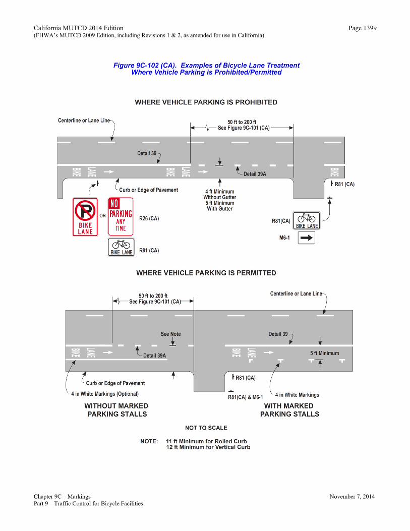
Bicycle Lane Treatment Where Vehicle Parking is Prohibited/Permitted Support:
31 Markings for a bike lane where vehicle parking is prohibited or permitted are shown in Figure 9C-102(CA). Standard:
32 Where motorist right turns are permitted, the solid bike lane shall either be dropped entirely, or dashed (Refer Bike Intersection lane, Detail 39A, shown in Figure 9C-101(CA)) beginning at a point between 50 feet and 200 feet in advance of the intersection. Option:
33 In areas where parking stalls are not necessary (because parking is light), a 4 inch solid white stripe may be painted to fully delineate the bike lane. This may be advisable where there is concern that motorists may misconstrue the bike lane to be a traffic lane.
BIKE LANE Pavement Markings Standard:
34 The BIKE LANE pavement markings shall be placed on the far side of each intersection. Option:
35 The BIKE LANE pavement markings may also be placed at other locations as desired. Support:
Revised March 9, 2018
California MUTCD 2014 Edition (FHWA’s MUTCD 2009 Edition, including Revisions 1 & 2, as amended for use in California)
Chapter 9C – Markings November 7, 2014 Part 9 – Traffic Control for Bicycle Facilities
Page 1383
36 Examples of BIKE LANE pavement markings are shown in various figures in this chapter. Option:
37 Optional word, arrow and symbol markings with details as shown in Figure 9C-3 may be used. Buffered Bicycle Lanes
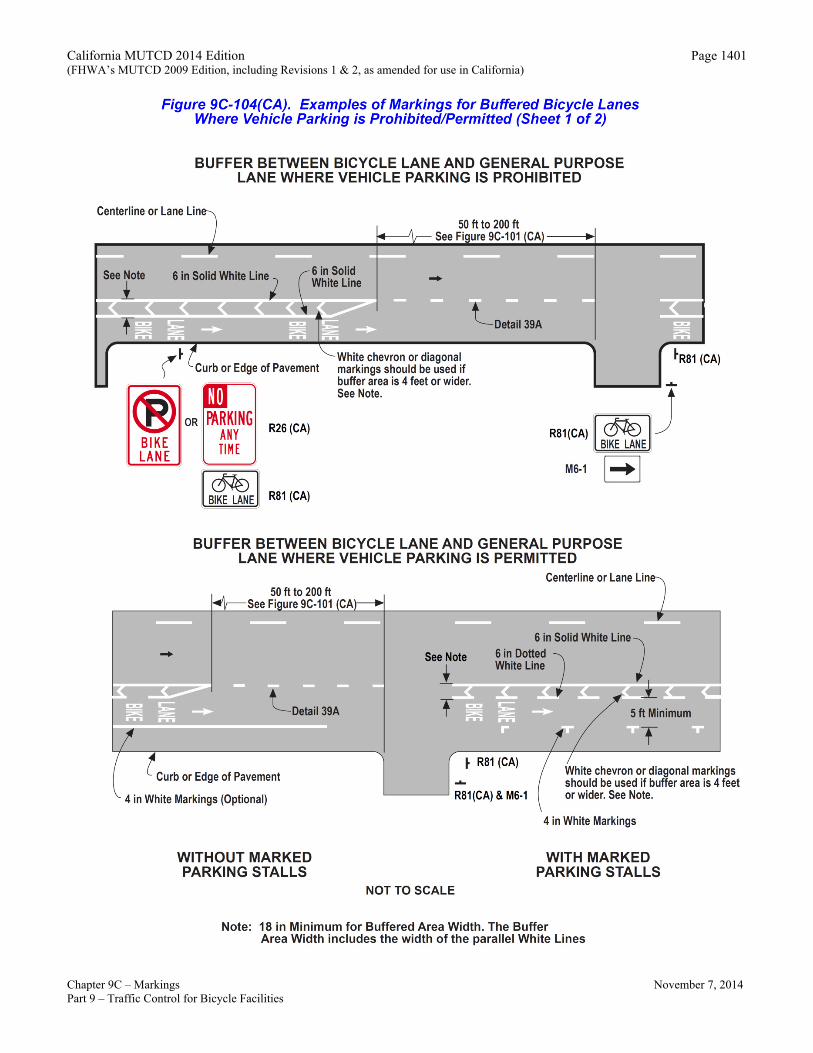
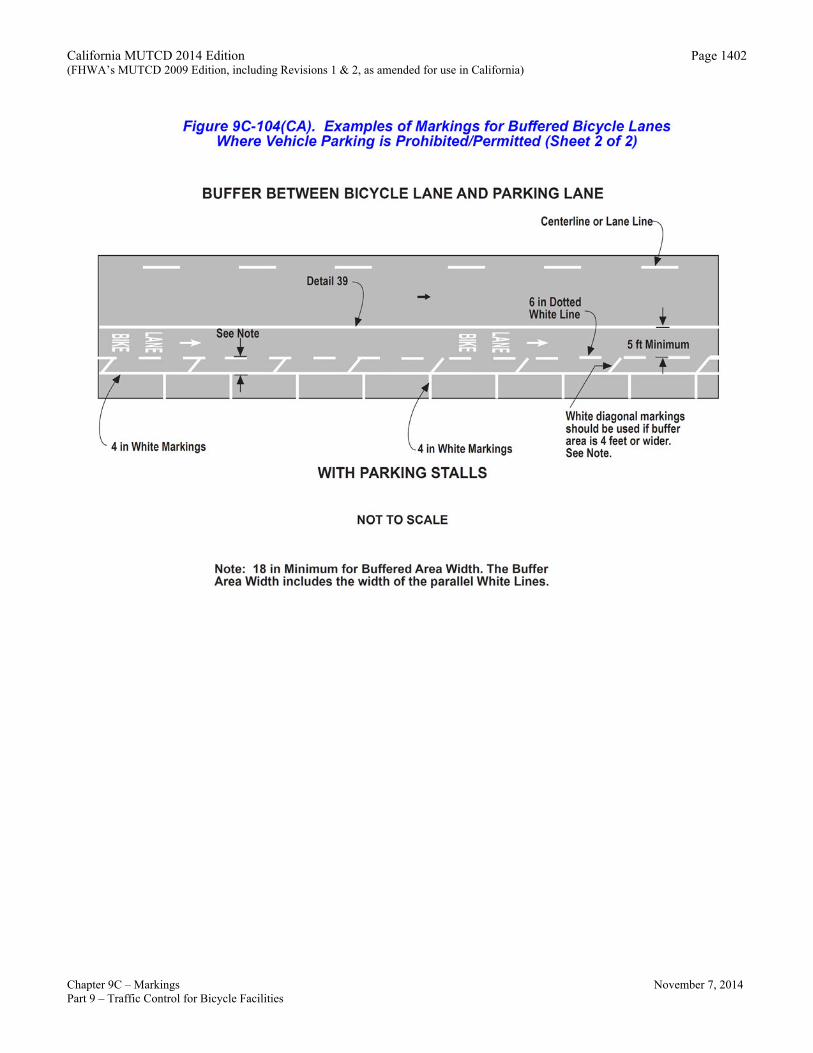
Support: 38 A buffered bicycle lane is a bicycle lane that is separated from the adjacent general-purpose lane or parking lane by a
pattern of standard longitudinal markings. The buffer area might include chevron or diagonal markings. The buffer area width includes the width of the parallel white lines.
39 Markings for buffered bicycle lanes are shown in Figure 9C-104(CA). 40 Pavement markings can designate a buffer area between a bicycle lane and adjacent general purpose lane and/or
parking lane. A buffer area provides a greater separation between the bicycle lane and adjacent lanes than is provided by a single normal or wide lane line. Option:
41 A bicycle lane buffer area may be used to separate a bicycle lane from an adjacent general-purpose lane and/or parking lane. Standard:
42 If used, a buffer area between a bicycle lane and general-purpose lane or parking lane shall be delineated by normal white longitudinal pavement markings. Guidance:
43 The use of chevron or diagonal markings should be considered in a bicycle lane buffer area and should be based on Section 3B.24 and engineering judgment.
44 If used, interior chevron or diagonal markings should consist of 4 inch lines angled at 45 degrees and striped at intervals of 10 to 40 feet. Support:
45 Increased interior chevron or diagonal marking frequency can increase motorist compliance. Option:
46 The chevron or diagonal markings may be omitted from bicycle lane buffer areas less than 4 feet wide. Guidance:
47 If used and where there is parking on the right side of the buffered bicycle lane, the rightmost line should be broken. Where vehicles are expected to cross the buffer area at driveways, both lines should be broken. Where neither condition exists, both lines should be solid.
48 End the buffer area on the approach to the intersection of side streets or major commercial driveways as shown in Figure 9C-104(CA).
Contraflow Bicycle Lanes Support:
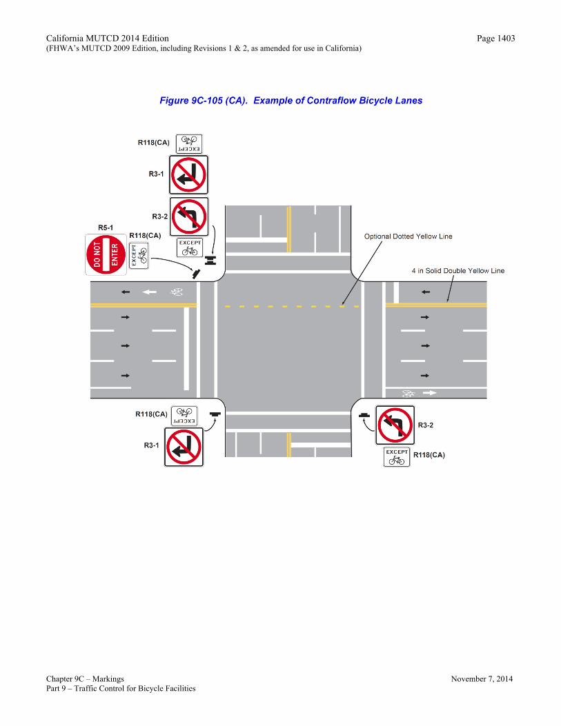
49 A contraflow bicycle lane is an area of the roadway designated to allow for the lawful use by bicyclists to travel in the opposite direction from traffic on a roadway that allows traffic to travel in only one direction.
50 Markings for contraflow bicycle lanes are shown in Figure 9C-105(CA). Standard:
51 Where used, a contraflow bicycle lane shall be marked on the left side of travel lanes so that contraflow bicycle travel is on the left of opposing traffic.
52 Where used, a contraflow bicycle lane shall be separated from opposite-direction travel by use of a solid double yellow center line marking, a painted median island, or raised median island.
53 Where intersection traffic controls along the street exist, (e.g., stop signs, flashing light signals, or traffic signals), appropriate devices shall be oriented toward bicyclists in the contraflow lane.
54 A contraflow bicycle lane shall not be installed on a two-way roadway. Guidance:
55 A buffer area per Section 3B.24 or an island should be used to separate the contraflow lane from adjacent travel lanes at posted speeds of 40 mph and above. Guidance:
56 Where signs are provided to regulate turns from streets or driveways that intersect with a roadway that has a contraflow bicycle lane, One Way (R6-1 or R6-2) signs should not be used. Turn Prohibition signs (R3-1 or R3-2) with supplemental
California MUTCD 2014 Edition (FHWA’s MUTCD 2009 Edition, including Revisions 1 & 2, as amended for use in California)
Chapter 9C – Markings November 7, 2014 Part 9 – Traffic Control for Bicycle Facilities
Page 1384
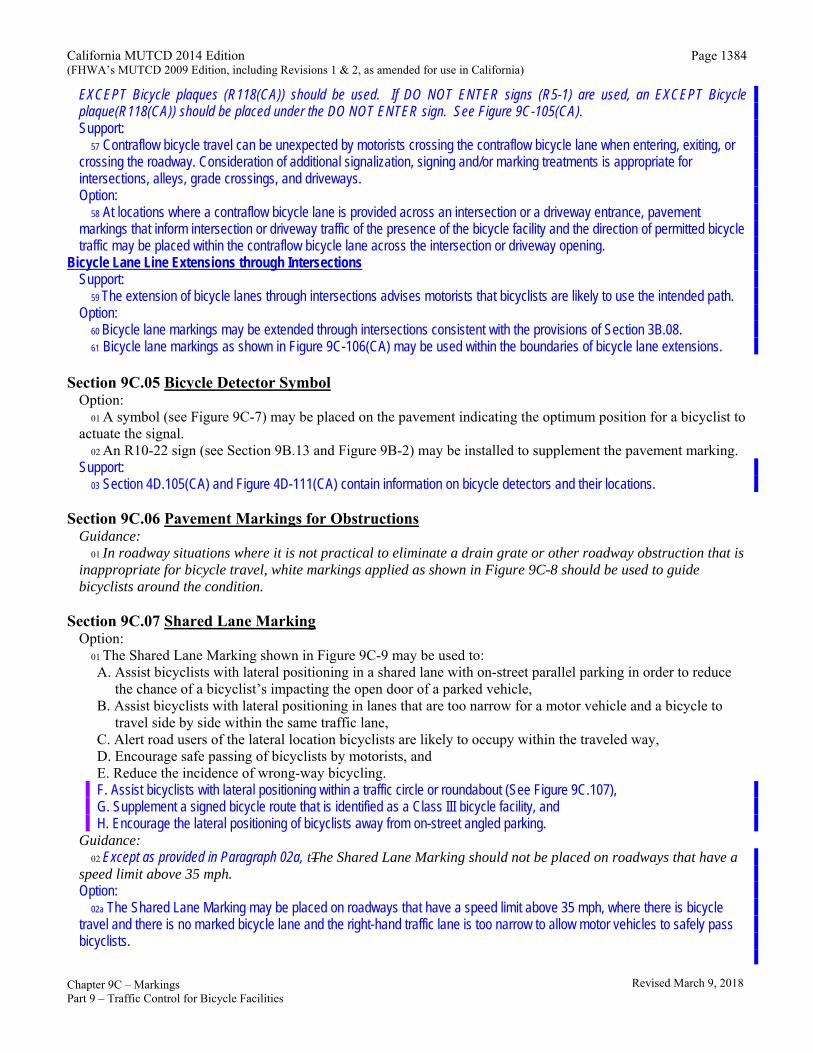
EXCEPT Bicycle plaques (R118(CA)) should be used. If DO NOT ENTER signs (R5-1) are used, an EXCEPT Bicycle plaque(R118(CA)) should be placed under the DO NOT ENTER sign. See Figure 9C-105(CA). Support:
57 Contraflow bicycle travel can be unexpected by motorists crossing the contraflow bicycle lane when entering, exiting, or crossing the roadway. Consideration of additional signalization, signing and/or marking treatments is appropriate for intersections, alleys, grade crossings, and driveways. Option:
58 At locations where a contraflow bicycle lane is provided across an intersection or a driveway entrance, pavement markings that inform intersection or driveway traffic of the presence of the bicycle facility and the direction of permitted bicycle traffic may be placed within the contraflow bicycle lane across the intersection or driveway opening.
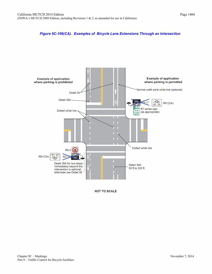
Bicycle Lane Line Extensions through Intersections Support:
59 The extension of bicycle lanes through intersections advises motorists that bicyclists are likely to use the intended path. Option:
60 Bicycle lane markings may be extended through intersections consistent with the provisions of Section 3B.08. 61 Bicycle lane markings as shown in Figure 9C-106(CA) may be used within the boundaries of bicycle lane extensions.
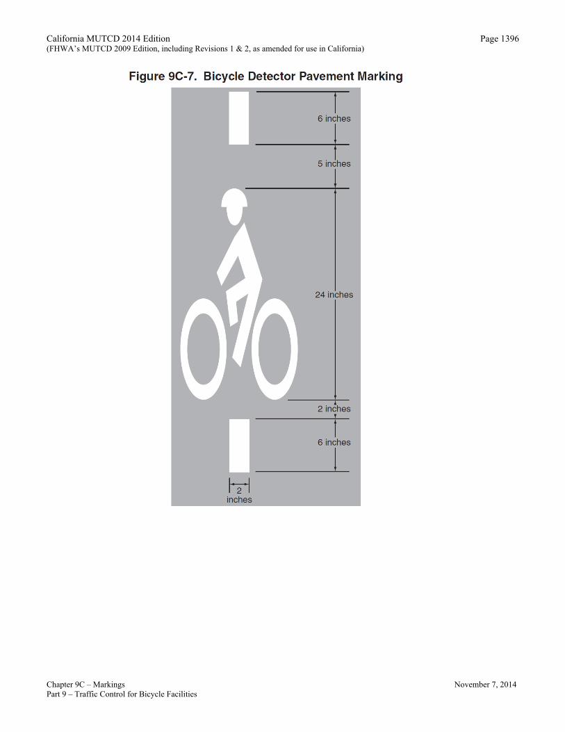
Section 9C.05 Bicycle Detector Symbol
Option: 01 A symbol (see Figure 9C-7) may be placed on the pavement indicating the optimum position for a bicyclist to
actuate the signal. 02 An R10-22 sign (see Section 9B.13 and Figure 9B-2) may be installed to supplement the pavement marking.
Support: 03 Section 4D.105(CA) and Figure 4D-111(CA) contain information on bicycle detectors and their locations.
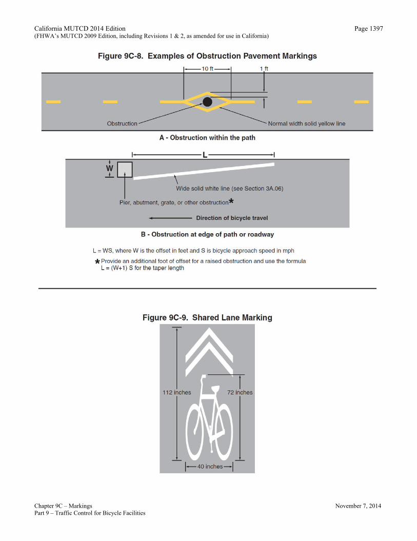
Section 9C.06 Pavement Markings for Obstructions
Guidance: 01 In roadway situations where it is not practical to eliminate a drain grate or other roadway obstruction that is
inappropriate for bicycle travel, white markings applied as shown in Figure 9C-8 should be used to guide bicyclists around the condition.
Section 9C.07 Shared Lane Marking
Option: 01 The Shared Lane Marking shown in Figure 9C-9 may be used to: A. Assist bicyclists with lateral positioning in a shared lane with on-street parallel parking in order to reduce
the chance of a bicyclist’s impacting the open door of a parked vehicle, B. Assist bicyclists with lateral positioning in lanes that are too narrow for a motor vehicle and a bicycle to
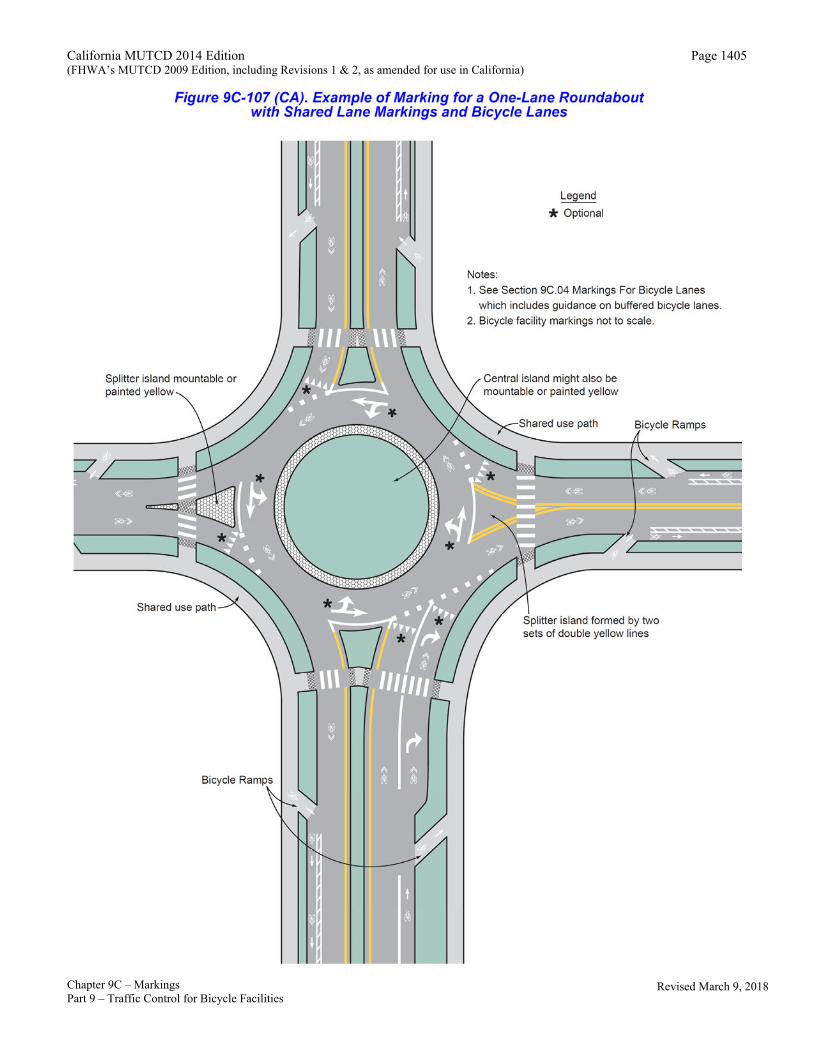
travel side by side within the same traffic lane, C. Alert road users of the lateral location bicyclists are likely to occupy within the traveled way, D. Encourage safe passing of bicyclists by motorists, and E. Reduce the incidence of wrong-way bicycling. F. Assist bicyclists with lateral positioning within a traffic circle or roundabout (See Figure 9C.107), G. Supplement a signed bicycle route that is identified as a Class III bicycle facility, and H. Encourage the lateral positioning of bicyclists away from on-street angled parking.
Guidance: 02 Except as provided in Paragraph 02a, tThe Shared Lane Marking should not be placed on roadways that have a
speed limit above 35 mph. Option:
02a The Shared Lane Marking may be placed on roadways that have a speed limit above 35 mph, where there is bicycle travel and there is no marked bicycle lane and the right-hand traffic lane is too narrow to allow motor vehicles to safely pass bicyclists.
Revised March 9, 2018
California MUTCD 2014 Edition (FHWA’s MUTCD 2009 Edition, including Revisions 1 & 2, as amended for use in California)
Chapter 9C – Markings November 7, 2014 Part 9 – Traffic Control for Bicycle Facilities
Page 1385
Support: 02b On roadways that have a speed limit above 35 mph, a Class II bikeway or Class IV bikeway is more appropriate to
facilitate bicycle travel. Standard:
03 Shared Lane Markings shall not be used on shoulders, separated bikeways or in designated bicycle lanes.
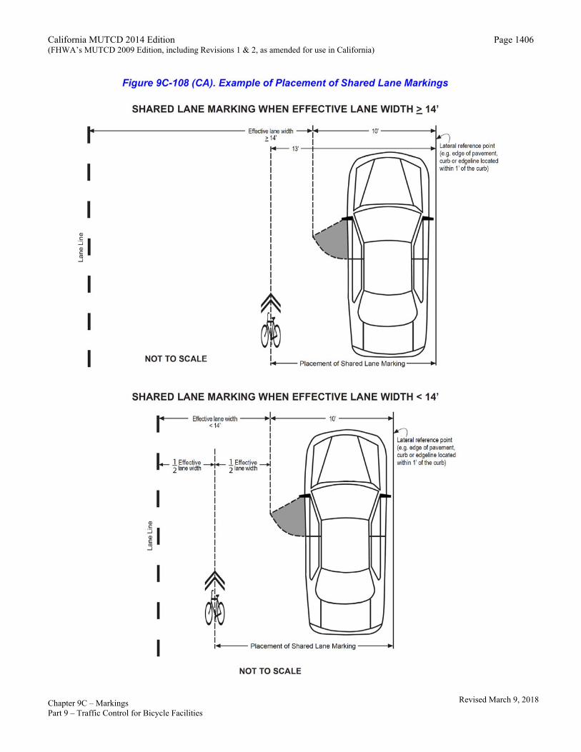
Lateral Positioning Support: 03a The effective lane width as used in this section indicates the width of the pavement available after subtracting the width
of the parked vehicle and door zone from the distance of the lane line/centerline to the face of the curb/edge of the pavement. Guidance:
04 If used in a shared lane with on-street parallel parking, if the effective lane width is 14 feet or greater, Shared Lane Markings should be placed so that the centers of the markings are at least 11 13 feet from the face of the curb, or from the edge of the pavement where there is no curb. If the effective lane width is less than 14 feet, the marking should be centered within the effective lane width. See Figure 9C-108(CA).
05 If used on a street without on-street parking that has an outside travel lane that is less than 14 feet wide, the centers of the Shared Lane Markings should be centered in the travel lane. If used on a street without on-street parking that has an outside travel lane whose width is 14 feet or greater, the shared lane markings should be centered at least 4 feet from the face of the curb, or from the edge of the pavement where there is no curb.
Support: 05a When a shared lane is sufficiently wide that motor vehicles can pass bicyclists within the lane, the purpose of the Shared
Lane Marking is to indicate a bicyclist line of travel that facilitates passing while avoiding fixed obstructions (e.g. drainage inlet, gutter joint). When a shared lane is not wide enough to enable passing with adequate clearance, the purpose of the marking is to indicate a bicyclist line of travel that deters passing within the lane. Spacing
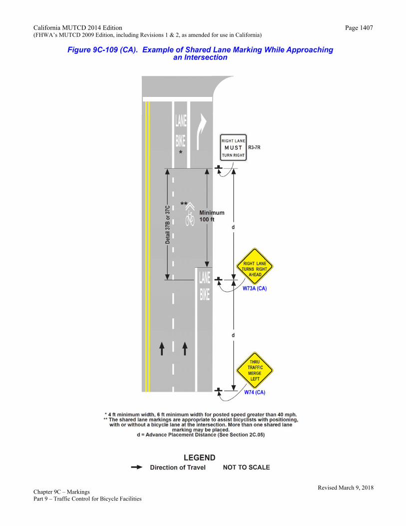
06 If used, the Shared Lane Marking should be placed immediately after an intersection and spaced at intervals not greater than 250 feet thereafter. Option:
06a Closer spacing between Shared Lane Markings may be considered approaching, traversing, and departing intersections, where there is higher potential for conflicts between motorists and bicyclists. See Figure 9C-109(CA).
06b Closer spacing between Shared Lane Markings may be considered where there are sight distance constraints, for example, approaching the crest of a vertical curve.
06c Closer spacing between Shared Lane Markings may be considered to guide bicyclists when deviating from a straight line of travel (e.g. merging, angled railroad crossing). Option:
07 Section 9B.06 describes a Bicycles May Use Full Lane sign that may be used in addition to or instead of the Shared Lane Marking to inform road users that bicyclists might occupy the travel lane.
Section 9C.101(CA) Barrier Posts on Class I Bikeways
Support: 01 Before a decision is made to install barrier posts, consideration needs to be given to the implementation of other remedial
measures, such as Bike Path Exclusion (R44A(CA)) signs (see Section 9B.08) and/or redesigning the path entry so that motorists do not confuse it with vehicle access.
02 It could be necessary to install barrier posts at entrances to bike paths to prevent motor vehicles from entering. When locating such installations, care needs to be taken to assure that barriers are well marked and visible to bicyclists, day or night (i.e., install reflectors or reflectorized tape).
California MUTCD 2014 Edition (FHWA’s MUTCD 2009 Edition, including Revisions 1 & 2, as amended for use in California)
Chapter 9C – Markings November 7, 2014 Part 9 – Traffic Control for Bicycle Facilities
Page 1386
Guidance: 03 An envelope around the barriers should be striped as shown in Figure 9C-8. If sight distance is limited, special advance
warning signs or painted pavement warnings should be provided. Where more than one post is necessary, 5 foot spacing should be used to permit passage of bicycle-towed trailers, adult tricycles, and to assure adequate room for safe bicycle passage without dismounting. Barrier post installations should be designed so they are removable to permit entrance by emergency and service vehicles. Support:
04 Generally, barrier configurations that preclude entry by motorcycles present safety and convenience problems for bicyclists. Guidance:
05 Such devices should be used only where extreme problems are encountered. Section 9C.102 (CA) Class IV Bikeways
Support: 01 Refer to FHWA “Separated Bike Lane Planning and Design Guide” for detailed information on planning and design of
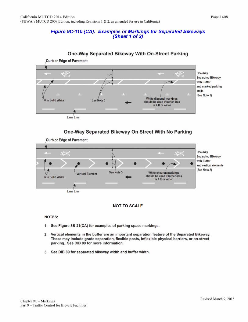
separated bike lanes. Option: 02 Separated bikeways may be delineated for one-way or two-way operation by using traffic control devices. Standard: 03 Vertical elements shall be used to define separated bikeways. Support: 04 Vertical elements in the buffer area are critical to separated bikeway design. Forms of vertical separation include, but are
not limited to, grade separation, flexible delineator posts, inflexible physical barriers, or on-street parking. See Figure 9C-110(CA). See DIB 89 for more information.
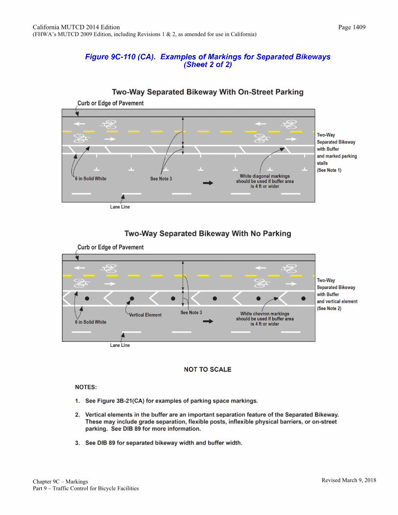
Standard: 05 Where separated bikeways are designed for two-way travel, a solid yellow line shall be used to separate the two
directions of travel where passing is not permitted. A broken yellow line shall be used where passing is permitted (Refer to Figure 9C-110(CA). See Section 9C.03 for marking patterns.
Option 06 A through separated bikeway may be positioned to the right of a right turn only lane or to the left of a left turn only lane, if
bicycle signals are used. See Section 4D.104 for optional use of Bicycle Signal Faces. Standard: 07 The Bike Symbol pavement markings or Helmeted Bicyclist Symbol (Figure 9C-3 Option A or Option B) shall be
placed on the far side of each intersection. Option: 08 The DO NOT ENTER (R5-1) sign with the supplemental EXCEPT Bicycle plaque (R118 (CA)) may be used on separated
bikeways to reduce the likelihood of accidental entrance by motor vehicles. Buffer Standard: 09 If used, the buffer area between the separated bikeway and general-purpose lane and parking lane (if present)
shall be delineated. 10 The buffer area shall be delineated by longitudinal pavement markings. See Section 9C.04 for buffer striping
details. Support: 11 The buffer area width includes the width of the parallel lines. 12 See DIB 89 for buffer area width requirements. Unobstructed passage Standard 13 If accessible parking or loading zones are provided on a roadway alongside a separated bikeway, then
unobstructed access shall be maintained.
Revised March 9, 2018
California MUTCD 2014 Edition (FHWA’s MUTCD 2009 Edition, including Revisions 1 & 2, as amended for use in California)
Chapter 9C – Markings November 7, 2014 Part 9 – Traffic Control for Bicycle Facilities
Page 1387
California MUTCD 2014 Edition (FHWA’s MUTCD 2009 Edition, including Revisions 1 & 2, as amended for use in California)
Chapter 9C – Markings November 7, 2014 Part 9 – Traffic Control for Bicycle Facilities
Page 1388
California MUTCD 2014 Edition (FHWA’s MUTCD 2009 Edition, including Revisions 1 & 2, as amended for use in California)
Chapter 9C – Markings November 7, 2014 Part 9 – Traffic Control for Bicycle Facilities
Page 1389
California MUTCD 2014 Edition (FHWA’s MUTCD 2009 Edition, including Revisions 1 & 2, as amended for use in California)
Chapter 9C – Markings November 7, 2014 Part 9 – Traffic Control for Bicycle Facilities
Page 1390
California MUTCD 2014 Edition (FHWA’s MUTCD 2009 Edition, including Revisions 1 & 2, as amended for use in California)
Chapter 9C – Markings November 7, 2014 Part 9 – Traffic Control for Bicycle Facilities
Page 1391
Revised March 9, 2018
California MUTCD 2014 Edition (FHWA’s MUTCD 2009 Edition, including Revisions 1 & 2, as amended for use in California)
Chapter 9C – Markings November 7, 2014 Part 9 – Traffic Control for Bicycle Facilities
Page 1392
Revised March 9, 2018
California MUTCD 2014 Edition (FHWA’s MUTCD 2009 Edition, including Revisions 1 & 2, as amended for use in California)
Chapter 9C – Markings November 7, 2014 Part 9 – Traffic Control for Bicycle Facilities
Page 1393
Revised March 9, 2018
California MUTCD 2014 Edition (FHWA’s MUTCD 2009 Edition, including Revisions 1 & 2, as amended for use in California)
Chapter 9C – Markings November 7, 2014 Part 9 – Traffic Control for Bicycle Facilities
Page 1394
California MUTCD 2014 Edition (FHWA’s MUTCD 2009 Edition, including Revisions 1 & 2, as amended for use in California)
Chapter 9C – Markings November 7, 2014 Part 9 – Traffic Control for Bicycle Facilities
Page 1395
California MUTCD 2014 Edition (FHWA’s MUTCD 2009 Edition, including Revisions 1 & 2, as amended for use in California)
Chapter 9C – Markings November 7, 2014 Part 9 – Traffic Control for Bicycle Facilities
Page 1396
California MUTCD 2014 Edition (FHWA’s MUTCD 2009 Edition, including Revisions 1 & 2, as amended for use in California)
Chapter 9C – Markings November 7, 2014 Part 9 – Traffic Control for Bicycle Facilities
Page 1397
California MUTCD 2014 Edition (FHWA’s MUTCD 2009 Edition, including Revisions 1 & 2, as amended for use in California)
Chapter 9C – Markings November 7, 2014 Part 9 – Traffic Control for Bicycle Facilities
Page 1398
California MUTCD 2014 Edition (FHWA’s MUTCD 2009 Edition, including Revisions 1 & 2, as amended for use in California)
Chapter 9C – Markings November 7, 2014 Part 9 – Traffic Control for Bicycle Facilities
Page 1399
California MUTCD 2014 Edition (FHWA’s MUTCD 2009 Edition, including Revisions 1 & 2, as amended for use in California)
Chapter 9C – Markings November 7, 2014 Part 9 – Traffic Control for Bicycle Facilities
Page 1400
California MUTCD 2014 Edition (FHWA’s MUTCD 2009 Edition, including Revisions 1 & 2, as amended for use in California)
Chapter 9C – Markings November 7, 2014 Part 9 – Traffic Control for Bicycle Facilities
Page 1401
California MUTCD 2014 Edition (FHWA’s MUTCD 2009 Edition, including Revisions 1 & 2, as amended for use in California)
Chapter 9C – Markings November 7, 2014 Part 9 – Traffic Control for Bicycle Facilities
Page 1402
California MUTCD 2014 Edition (FHWA’s MUTCD 2009 Edition, including Revisions 1 & 2, as amended for use in California)
Chapter 9C – Markings November 7, 2014 Part 9 – Traffic Control for Bicycle Facilities
Page 1403
California MUTCD 2014 Edition (FHWA’s MUTCD 2009 Edition, including Revisions 1 & 2, as amended for use in California)
Chapter 9C – Markings November 7, 2014 Part 9 – Traffic Control for Bicycle Facilities
Page 1404
California MUTCD 2014 Edition (FHWA’s MUTCD 2009 Edition, including Revisions 1 & 2, as amended for use in California)
Chapter 9C – Markings November 7, 2014 Part 9 – Traffic Control for Bicycle Facilities
Page 1405
Revised March 9, 2018
California MUTCD 2014 Edition (FHWA’s MUTCD 2009 Edition, including Revisions 1 & 2, as amended for use in California)
Chapter 9C – Markings November 7, 2014 Part 9 – Traffic Control for Bicycle Facilities
Page 1406
Revised March 9, 2018
California MUTCD 2014 Edition (FHWA’s MUTCD 2009 Edition, including Revisions 1 & 2, as amended for use in California)
Chapter 9C – Markings November 7, 2014 Part 9 – Traffic Control for Bicycle Facilities
Page 1407
Revised March 9, 2018
California MUTCD 2014 Edition (FHWA’s MUTCD 2009 Edition, including Revisions 1 & 2, as amended for use in California)
Chapter 9C – Markings November 7, 2014 Part 9 – Traffic Control for Bicycle Facilities
Page 1408
Revised March 9, 2018
California MUTCD 2014 Edition (FHWA’s MUTCD 2009 Edition, including Revisions 1 & 2, as amended for use in California)
Chapter 9C – Markings November 7, 2014 Part 9 – Traffic Control for Bicycle Facilities
Page 1409
Revised March 9, 2018