Embed Size (px)
Citation preview

HIGHWAYS AGENCY NETWORK MANAGEMENT MANUAL
Version 1 Amend. No
8 Issue Date
July 09
PART 3 - ROUTINE SERVICE
CONTENTS Chapter Page No.
3.1 General 3.1-1
3.1.1 Introduction 3.1.2 Inspections 3.1.3 Information Management 3.1.4 Operations Plans & Manuals
3.2 Paved Areas 3.2-1
3.2.1 General 3.2.2 Carriageways 3.2.3 Footways & Cycle Tracks 3.2.4 Covers, gratings, frames & boxes 3.2.5 Kerbs, edgings & pre-formed channels
3.3 Drainage 3.3-1
3.3.1 General 3.3.2 Piped drainage systems 3.3.3 Gullies, catchpits, grit traps, interceptors, soakaways, & manholes 3.3.4 Piped grips 3.3.5 Grips 3.3.6 Ditches 3.3.7 Filter drains & fin/narrow filter drains 3.3.8 Culverts 3.3.9 Vegetative drainage systems for highway runoff 3.3.10 Ancillary items 3.3.11 Linear drainage systems 3.3.12 Road-edge surface water channels 3.3.13 Grassed surface water channels 3.3.14 Flooding
3.4 Geotechnical Asset Management 3.4-1
3.4.1 General 3.4.2 Geotechnical Asset Management 3.4.3 Provision of the Geotechnical Asset Management Plan 3.4.4 Standards and Guidance
3.5 Structures 3.5-1
3.5.1 General 3.5.2 Maintenance responsibilities 3.5.3 Cyclic maintenance 3.5.4 The management of sub-standard highway structures, concrete half deck
and hinge deck structures

HIGHWAYS AGENCY NETWORK MANAGEMENT MANUAL
Version 1 Amend. No
8 Issue Date
July 09
Chapter Page No. 3.6 Tunnels 3.6-1
3.6.1 General 3.6.2 The Road Tunnel Safety Regulations 2007 3.6.3 Operation 3.6.4 Cleaning 3.6.5 Ventilation 3.6.6 Lighting 3.6.7 Drainage 3.6.8 Paved area 3.6.9 Slope & ground stability adjacent to portals 3.6.10 Tunnel corrosive environment 3.6.11 Anchors & mechanical supporting systems
3.7 Road Restraint Systems 3.7-1
3.7.1 General 3.7.2 Repairs and Maintenance 3.7.3 Lane Restrictions at Barrier repairs 3.7.4 Dealing with fluid & gas build-up in aluminium parapets
3.8 Highways Agency Traffic Management Systems (HATMS) 3.8-1
3.8.1 General 3.8.2 Maintenance Aspects 3.8.3 Requirements for NTCC & TiS Equipment 3.8.4 Regional Control Centres 3.8.5 TechMAC 3.8.6 National Roads Telecommunications Services (NRTS) 3.8.7 Design & Installation of the telecommunications network by GeneSYS
3.9 Road markings & Road Studs 3.9-1
3.9.1 General 3.9.2 Road markings 3.9.3 Road studs
3.10 Road traffic signs 3.10-1
3.10.1 General 3.10.2 Maintenance of Traffic Signs with Dew Resistant Coatings
3.11 Road traffic signals 3.11-1
3.11.1 General
3.12 Lighting 3.12-1
3.12.1 General 3.12.2 Innovation

HIGHWAYS AGENCY NETWORK MANAGEMENT MANUAL
Version 1 Amend. No
8 Issue Date
July 09
Chapter Page No. 3.13 Soft estate 3.13-1
3.13.1 General 3.13.2 Access 3.13.3 Woodlands, Trees and Hedgerows 3.13.4 Grasslands 3.13.5 Conservation Wetlands 3.13.6 Weeds 3.13.7 Cultural Heritage Asset
3.14 Sweeping & Cleaning 3.14-1
3.14.1 General
3.15 Fences, walls, screens, & environmental barriers 3.15-1
3.15.1 General
3.16 Retained Litter Clearing Duties 3.16-1
3.16.1 General 3.16.2 Inspection requirements
3.17 The Landfill Directive and Liquid Waste 3.17-1
3.17.1 Purpose 3.17.2 Background 3.17.3 Action Required 3.17.4 Appendix A – Landfill Directive Interpretation Note 1
3.18 Environmental implications of maintenance operations 3.18-2
3.18.1 Introduction 3.18.2 Investigation 3.18.3 Design considerations
3.19 Health & Safety Management within Depots 3.19-1
3.19.1 General 3.19.2 Service Provider’s Duties and Responsibilities 3.19.3 Access requirements 3.19.4 Management Procedures 3.19.5 Quarterly Review 3.19.6 Monthly Inspection
3.19.6.1 QRC Initial Health and Safety Meeting Notes (Checklists) 3.19.6.2 MIC Monthly Inspection Report

HIGHWAYS AGENCY NETWORK MANAGEMENT MANUAL
Version 1 Amend. No
8 Issue Date
July 09
Chapter Page No. 3.20 Identification of Workplace Hazards 3.20-1
3.20.1 General 3.20.2 Depots as Places of Work 3.20.3 Work Equipment 3.20.4 Hazardous Substances and Preparations 3.20.5 Flammable, Toxic and Corrosive Substances and Preparations 3.20.6 Manual Handling Operations 3.20.7 Electricity at Work 3.20.8 Winter Maintenance, Equipment and Vehicles 3.20.9 Salt Loading Equipment, Storage and Handling 3.20.10 Personal Protective Equipment
Annexes
Annex 3.5.1 The Management of Sub-Standard Highway Structures, Concrete Half Deck and Hinge Deck Structures – Background Information A3.5.1

Part 3 Chapter 3.1 General
Version 1 Amend. No
8 Issue Date
July 09 3.1. 1
3.1 General 3.1.1 Introduction The aim of the advice is to make available practices that have been found to achieve the required performance level. Advice is provided for each Technical Area on how the performance requirements can be achieved for that aspect of the Routine Service: • Aspects of condition that are likely to indicate failure to meet the performance requirements • Reference to Design Standards and Advice Notes that describe the performance requirements
in more detail • Advice on further activities to undertake that will aid the achievement of the performance
requirements The aim of the advice is to make policies that have been found to achieve the required performance and provide examples of best value. 3.1.2 Inspections All inspections must be co-ordinated, as fully as possible, with the inspections of items in the highway as a whole (e.g. Deflectograph survey,) or in the case of covers, gratings, frames and boxes with the cleaning out of highway gullies, catchpits and interceptors. Wet weather inspections must be undertaken at locations causing concern even if a dry weather inspection has been undertaken (e.g. every 4th Inspection). Inspections should be carried out with hand-held data collection devices (DCD), using standard data capture programs that include check-lists setting out the various defects to be noted. The data must be downloaded into the database management system when the inspection has been completed. The Service Manager's RMMS Manual gives guidance on the items to be inspected and defects to be noted. Check-lists are programmed on to the DCDs for recording the inspections, enabling quick reference on site. 3.1.2.1 Detailed Inspections Detailed inspections are generally to identify defects in all Technical Areas except structures and tunnels. For structures and tunnels, General and Principal inspections are used. Arrangements for detailed inspections must seek to minimise disruption to traffic whilst providing adequate access for proper inspections and maintaining a safe working environment for the inspectors. Wherever possible, inspections that require lane closures should be carried out when closures are in operation for other maintenance work. Where separate lane closures are necessary, inspections should be undertaken in off-peak periods and consideration given to night-time working or mobile lane closures to keep delays to road users to a minimum and reduce the risk of accidents. Detailed inspections for defects in and along the edges of dual 3-lane carriageways, or wider, must be carried out from the hard shoulder or grass verge/nearside lane. The condition of the carriageway surface, road studs and road markings in all lanes must also be observed from the edge of the carriageway together with gullies, kerbing and edges adjacent to the nearside verge and central reservation.

Part 3 Chapter 3.1 General
Version 1 Amend. No
8 Issue Date
July 09 3.1. 2
Using lane closures in place for other purposes, previous experience has shown that a Detailed Inspection can be carried out from the central reserve, with the offside lane coned off. This Inspection can cover all items within and adjacent to the central reserve. Additionally, the centre and offside lanes of the carriageway, as well as the road markings and road studs between the lanes, must be inspected. For 2-lane dual carriageways, inspections from the hard shoulder and grass verge/nearside lane should be adequate for recording defects across the full carriageway width. Offside lane restrictions for these roads should only be adopted to protect personnel inspecting items within the central reservation. The Detailed Inspection record must include details of the manner of Inspection (e.g. offside lane closure or hard shoulder), the weather conditions and any other unusual features of the inspection. Nil returns must be recorded in the database. 3.1.2.2 General Inspections A General Inspection comprises a visual inspection of all parts of the structure or tunnel that can be inspected without the need for special access equipment or traffic management arrangements. General Inspections are fully described in BD63 and BD53. 3.1.2.3 Principal Inspections A Principal Inspection is more comprehensive and provides more detailed information than a General Inspection. A Principal Inspection comprises a close examination, within touching distance, of all inspectable parts of a structure and tunnel. Principal Inspections are fully described in BD63, BD53 and HD41. It should be noted that periodic inspection and testing of electrical installations must also be in accordance with BS 7671 as required for particular items. Consideration should be given to the co-ordination of BS 7671 inspections and testing with Principal inspections. 3.1.2.4 Special Inspections A Special Inspection for structure or tunnel may comprise a close visual inspection, testing and/or monitoring and may involve a one-off inspection, a series of inspections or an on-going programme of inspections. As such, Special Inspections are tailored to specific needs. Special Inspections are fully described in BD63 and BD53. 3.1.2.5 Safety Inspections Safety inspections are regular visual inspections designed to identify the presence of Category 1 defects and are traditionally carried out by 2 trained personnel operating together from a slow moving vehicle. In particular circumstances (e.g. in town centres, principal shopping areas, subways, footbridges and at complex road junctions) inspection personnel may need to proceed on foot either to confirm suspected faults or to complete the Inspection. It may be appropriate to undertake Safety inspections at off-peak times or at night in order to minimise the traffic disruption and maximise the safety of both the inspectors and the public. It is important to remember that Safety Inspections also cover highway structures and tunnels and must identify obvious deficiencies which represent, or might lead to, a danger to the public and therefore require immediate or urgent attention; details are provided in BD63 and BD53. Safety Inspection data must be loaded into the management database including those showing a nil return. Safety Inspection records include details of the weather conditions, road surface condition and any unusual features of the method of inspection.

Part 3 Chapter 3.1 General
Version 1 Amend. No
8 Issue Date
July 09 3.1. 3
Certain very vulnerable sites (e.g. Severn Bridge and all road tunnels) may be subject to continuous surveillance. This surveillance is, generally, largely dependent on video monitoring and is primarily designed to generate prompt response to traffic incidents. The monitoring should not be considered automatically as an alternative to Safety inspections. Reports and complaints received from other sources must be similarly recorded on the database and retained together with details of specific inspections and actions taken. 3.1.2.6 Safety Patrols The function of Safety Patrols is to supplement Safety inspections by providing a structured, more frequent surveillance of the road network to identify obvious hazards (Category 1 defects). A Safety Patrol is normally carried out by an inspector in a vehicle travelling slowly at prevailing traffic speeds, without disrupting the traffic flow. At particular sites it may be appropriate for Safety Patrols to be undertaken on foot. A record must be made of all Safety Patrols undertaken, including the date, the inspector, the method, and the time that each section of the road was patrolled. Safety Patrols have traditionally been undertaken on Category A roads between the Safety inspections. The road category and local circumstances will determine the frequency of the patrols. At junctions it will generally be unnecessary to patrol the main carriageway and all the associated slip roads, but at more complex interchanges it may be necessary to cover only some of the link roads. A schedule of the link roads and slip roads to receive Safety Patrols must be agreed with the Service Manager. 3.1.3 Information Management Valuable information may be gained from records of repairs. For example, a high incidence of repairs at a location can highlight the need to consider a more widespread treatment. The Service Provider is required to ensure that all relevant data pertaining to the performance of the Highways Agency’s assets is recorded in the Highways Agency’s operational Asset Databases. This includes the updating of the record sets as a result of both maintenance activities and inspections/surveys. 3.1.4 Operations Plans and Manuals Operations plans and manuals form the equipment manufacturers’ recommendations and must be taken as a starting point for scheduling equipment maintenance. These schedules are normally described as time intervals based on maximum use but actual use may be less. Conversely, the environment may be more aggressive than is assumed by manufacturers at the time of installation and this may act to shorten the life of equipment. Before amending the operations plan, a qualified person must gather and analyse operational information based on past performance. Other means of identifying the need for servicing, such as remote monitoring, may also be adopted. The reasons for any variations to the maintenance schedules to achieve the performance requirements must be recorded and the effects of the changes monitored and reviewed.
Part 3 Chapter 3.2 Paved Areas
Version 1 Amend. No
8 Issue Date
July 09 3.2. 1
3.2 Paved Areas 3.2.1 General Particular attention must be paid to potholes and other localised defects since these may often constitute an immediate or imminent hazard. Such localised defects must be dealt with by Service Providers so as to protect road users and minimise user delays. Routine and structural maintenance activities that are similar in nature should be differentiated. It is usual, before carrying out resurfacing or other surface treatment, to ensure that the underlying road structure is sound. This often requires repairs to potholes, rutting, open joints, etc., that would otherwise be carried out as routine activities if no renewal work is planned.
The repair of defects reported from inspections may be absorbed into renewal works already due to be carried out in the planned maintenance programme. However, renewal works will usually be contained within the planned maintenance programme, determined on the basis of national priorities. When these schemes are deferred, routine maintenance repairs may be needed separately and at relatively short notice. 3.2.2 Carriageways Conditions that are likely to prevent the achievement of the performance requirements include: All Carriageways • Difference in level between items (such as covers, gratings, frames and boxes) and the
abutting carriageway, or differential levels between different components, exceeding 20mm. • Parallel gullies and other gratings in carriageways, which have gaps more than 20mm wide
parallel to the normal line of movement of pedal and motor cycles. • Overgrown vegetation that is causing a hazard by encroaching on sight lines. Flexible surfacing • Localised cracking or breaking up (including edge deterioration) confined to a discrete area of
the carriageway, or around a reinstated trench or patch and not associated with structural maintenance activities. This includes cracking or breaking up around ironwork, a difference in the level of a reinstated trench or patch with the surrounding carriageway and potholes.
• Depressions exceeding 20mm • Fretting, or loss of material from the carriageway surface, or around a reinstated trench or
patch • Open or excessive surfacing joints wider than 20mm. Concrete surfacing • Spalling at joints and cracks, opening of longitudinal joints, failure of sealed cracks, vertical
movement resulting in stepping at a joint or crack and also cracking. • Dynamic movement under traffic at joints and cracks caused by lack of support from the sub-
base or lack of, or ineffective, load transfer dowels or tie bars at joints. Dynamic movement is also associated with mud pumping, the usual signs of which are muddy stains on the surface of the slab.
• Vertical movement of slabs, observed in the form of settlement of the slab. • Crazing or scaling of surface, and a loss of texture.

Part 3 Chapter 3.2 Paved Areas
Version 1 Amend. No
8 Issue Date
July 09 3.2. 2
• Failed repairs, such as failure of overbanding or sealed cracks. HD31 and HD32 give recommendations for the maintenance and repair of flexible and concrete pavements respectively. Repair procedures for carriageways are described in SHW Series 700, 800, 900, 1000 and 1100. Some minor carriageway repairs may be due to the activities of the Statutory Undertakers or licence holders who are governed by the New Roads and Street Works Act 1991. From 1st January 1993 if the excavation is still within its guarantee period and fails to meet the performance criteria, as defined in Paragraph S1.2 and Chapter S2 of the Specification for the Reinstatement of Openings in Highways, the Undertaker must be informed of the defect, using the procedure contained in Chapter 4 of the Code of Practice for inspections and the defect inspection procedure invoked. If a potentially hazardous reinstatement is discovered, the reinstatement must be protected by signing, lighting and guarding while awaiting the Undertaker. In exceptional circumstances, (where there are safety implications for the road users), the reinstatement may be made safe by the Service Provider. Any costs incurred in making safe a reinstatement must be recovered from the Undertaker. During the reinstatement guarantee period the Undertaker remains responsible for the maintenance and performance. However, defects at this stage may be picked up as a result of one of the inspection procedures.
3.2.3 Footways and cycle tracks To meet the requirement for sustainable travel and accessibility, one objective is to provide safer and more acceptable facilities for pedestrians, cyclists and other vulnerable road users (such as horse riders). In the case of horse riders, particular emphasis is placed on the crossing of trunk roads using overbridges, and improving links to other destinations. Satisfactory surfaces on footways and cycle tracks may encourage walking and cycling respectively. Footways include the walking surfaces of subways, underbridges, overbridges and pedestrian rights of way which are the responsibility of the Service Manager and may occasionally fall outside the Highway Boundary. HD39 and HD40 give advice on the construction and maintenance of footways. A cycle track is a paved facility available for persons with pedal cycles, with or without a right of way on foot, usually within the Highway Boundary. Defects on footways and cycle tracks affect safety, maintenance and serviceability. Compensation claims may result from defects that have not been repaired. Therefore, a pro-active rather than a re-active approach is needed, to identify defects before they become hazardous. Conditions that are likely to prevent the achievement of the performance requirements include: Footways and cycle tracks • Unevenness, including ridges, projections, sharp edges (trips), cracks and gaps (>20mm).
Block profiles, which include ridges, projections, sharp edges (trips) with a difference in level (>20mm), cracks and gaps (>20mm wide). Also slab rocking that creates a hazardous upstand (>20mm).
• Potholes, loss of material or small areas of depression (>25mm) which are creating or are likely to create a hazard.
• Local cracking of the asphalt surface confined to a discrete area or extensive cracking affecting the major part of a footway/cycle track. Fretting (loss of material leaving the coarse aggregate proud of the matrix or causing loss of coarse aggregate). Failed patch with adjacent cracking, loss of material from an existing area of patching, and difference in level (> 20mm) and depressions (> 25mm) that are creating a hazard.

Part 3 Chapter 3.2 Paved Areas
Version 1 Amend. No
8 Issue Date
July 09 3.2. 3
• Trench reinstatement and adjacent cracking, loss of material (fretting) from a reinstated trench, and difference in level, (which applies when a trench has subsided or has been left proud following reinstatement and includes ridges, projections, sharp edges (trips), cracks and gaps (>20mm) and also depressions (>25mm)). A temporary reinstatement with a 10mm upstand or depression associated with a temporary reinstatement that poses a risk to users.
• Hazards such as fallen trees, unsafe signing, lighting or guarding of excavations, unsafe steps, persistent snow, ice or leaves, contaminants (such as oil) giving rise to slipping, a loose surface or encroachment by vegetation.
Footways • Standing water (>10mm deep), which restricts the footway width to less than 500mm or is
likely to cause pedestrians to use the adjacent carriageway. This is particularly a problem when the water freezes.
• Difference in levels between items (covers, gratings, frames and boxes) and abutting footway, or differential levels between different components (> 20mm).
Cycle tracks • Standing water (>10mm deep), which restricts the cycle track width or is likely to cause cyclists
to use the adjacent carriageway. This is particularly a problem when the water freezes. • Parallel gullies and other gratings in cycle tracks with wide gaps (>20mm), parallel to the
normal line of movement of pedal cycles. • Difference in levels between items (such as covers, gratings, frames and boxes) and the
abutting cycle track surface, or differential levels between different components (> 20mm). Particular consideration must be given to defects, such as trips, which may constitute an immediate danger to pedestrians and/or cyclists. It should be noted that some hazards are likely to be seasonal. SHW Series 1100, HD39 and HD40 describe repair procedures for footways and cycle tracks. Some defects may result from the activities of the Statutory Undertakers or licence holders who are governed by the New Roads and Street Works Act 1991. If defects occur, within the guarantee period, as defined in the Specification for the Reinstatement of Openings in Highways, the Undertaker must be informed of the defects, using the procedure contained in the Code of Practice for Inspections. Occasionally, footways and cycle tracks adjacent to rural and urban trunk roads, may become disused. This may be due to unnecessary provision in the first place or changes in circumstances over the passage of time, or it may be due to an actual or perceived hazard. The reason for disuse needs to be established and if it is decided that it is due to unnecessary provision or change of use, then it may be appropriate to reduce the frequency of assessments. Judgement will be needed to decide if the facility is indeed disused and the situation will need to be monitored since it may return to use. For example a little used facility in an urban area may be considered for re-classification as "rural" for maintenance purposes. Where a disused facility represents a significant maintenance liability, consideration should be given to removing it. Damage to the footways may be caused by vehicle over-riding, particularly in urban areas and at road junctions where the footway may be immediately adjacent to the carriageway edge. Consideration should then be given to the provision of high strength in-situ concrete margins up to 1m wide behind the kerb or locally at road junction radii. Alternatively, consideration should be given to carrying out an improvement scheme to alleviate the problem in which case a report and proposal for action should be made to the Service Manager. HD40 provides further advice.

Part 3 Chapter 3.2 Paved Areas
Version 1 Amend. No
8 Issue Date
July 09 3.2. 4
Pre-cast concrete footway slabs that have superficial cracks only must not be replaced as a routine maintenance operation unless there is a need to reset the slab because of other defects. 3.2.4 Covers, gratings, frames and boxes Conditions that are likely to prevent the achievement of the performance requirements include: • Covers or gratings that constitute an immediate hazard, particularly by a relative movement
under load exceeding 10mm. In urban areas, rocking covers or gratings causing noise should be identified as a defect with a high priority for treatment.
• Cracked or broken items which may be in danger of collapse and thus liable to cause a hazard.
• Worn covers are a hazard for pedal and motor-cycles from skidding in wet conditions. • Missing items are likely to constitute a hazard.
Covers situated in verges that are traversed by pedestrians must not be ignored, as they may pose a hazard. It may often be difficult to decide whether a cracked or broken item is in real danger of collapse. If in doubt, it must be replaced, irrespective of its position. SHW Series 500 describes the repair procedures for covers, gratings, frames and boxes. Defects in covers and gratings may pose particular danger to pedal and motor-cycle users. It should be remembered that occupancy of the road by these road users will not always be limited to the nearside lane and that the potential hazards affecting them may also occur in other lanes. Rocking gratings or covers with only small movement under load may nevertheless be a nuisance in urban areas because of the intrusive noise they make. If complaints are received, they should be corrected. When inspecting the gratings of gullies and other similar surface water catchment items, the opportunity should be taken to check that the item is functioning satisfactorily and is not partially or wholly blocked. 3.2.5 Kerbs, edgings and pre-formed channels Conditions that are likely to prevent the achievement of the performance requirements include: • Vertical projections (> 20mm) and horizontal projections (> 50mm) • Loose / rocking / damaged kerbs and/or damaged, edgings and pre-formed channels of all
types which are creating or are likely to create a hazard or lead to loss of support or protection. • Poor local alignment of pre-formed channels which could give rise to danger or nuisance from
standing water or damage to the highway structure caused by water penetration. • Missing kerbs, edgings and pre-formed channels of all types Although kerbs, edgings and pre-formed channels, tend to be stable by their nature and construction specification, hazardous conditions can develop quickly when either individual kerbs, or short lengths, are damaged or moved out of alignment by heavy vehicles, or by local subsidence. Frequent damage by heavy vehicles may suggest the need for local re-alignment or a more robust treatment. Short lengths of kerb serving gullies or grips must not be overlooked. SHW Series 1100 describes repair procedures for kerbs, edgings and pre-formed channels.
Part 3 Chapter 3.3 Drainage
Version 1 Amend. No
8 Issue Date
July 09 3.3. 1
3.3 Drainage 3.3.1 General Adequate drainage facilities must be present and operate correctly to: • Avoid the accumulation of water on the trafficked surfaces of the highway that reduces the
safety of the road user. • Adequately drain the road pavement structure to reduce maintenance liabilities and help
realise the design life of the road. • Avoid disruption to the traffic flow caused by flooding. • Prevent nuisance to adjoining landowners caused by flooding. • Avoid polluted effluent, from the highway drainage facilities, being directed indiscriminately
into watercourses. • Avoid reuse/recycle of runoff effluent during drains cleansing operations
Conditions that are likely to prevent the achievement of the performance requirements are: • Full or partial blockage • Standing water • Detritus /refuse / weed growth / roots are all likely to reduce flow, damage the structure and
may appear unsightly. • Cracking / deformation / alignment of components of the drainage system adversely affecting
the structural or hydraulic performance or durability of components of the system. • Complete structural failure of components of the drainage system. • Removal of material in the invert (scour) adversely affecting the hydraulic or structural
performance or durability of components of the system. • Removal of material in sides/ banks / walls / bunds by erosion • Complete or partial blocking of filter material. • Displacement of surface filter material • Inadequate flow of water prevents self-cleaning. • Surcharge of water not contained within the drainage system. • Inadequate facilities for the removal of water from the balancing pond • Failure or incorrect operation of equipment associated with outfall regulating device pump /
sluice / tidal flap / headwall / apron / penstock • Damage to grassed surface water channels (e.g. by vehicle overrun). • Loose, rocking, ridges, projections, sharp edges (trips), cracks and gaps that result in an
element of the linear drainage system projecting >20mm. • Flooding of the highway, adjoining property or services caused by the inadequate provision or
operation of highway drainage, or other facilities.
The Service Provider is reminded that consideration must to be given to the likely presence of protected species in all drainage features and that appropriate advice must be sought from an ecologist or the regional environmental advisor, before commencing work.

Part 3 Chapter 3.3 Drainage
Version 1 Amend. No
8 Issue Date
July 09 3.3. 2
3.3.2 Piped drainage systems Records of the condition and location of the drainage network, in a standard format will greatly assist the interpretation of the likely performance and the repair of the highway drainage network. In particular, CCTV surveys of the existing drainage network have been adopted for a comprehensive record of the type and condition of drainage facilities. Ownership of the piped drainage systems must be established and indicated on the record. If properly designed and constructed, piped drainage systems should normally be self-cleansing and maintenance is only necessary when a blockage or another fault occurs. Those parts of a system that often give trouble (e.g. are prone to flooding) will be known or faults can be identified from safety inspections, or reports and complaints received from other sources. Symptoms of blockage or faults that prompt further investigation include: backing up and flooding at the entry points to the piped drainage system; dry outfalls; wet areas on verges; and the presence of lush vegetation. Suitable methods of inspection include: • Inspection of the facilities during gully, manhole, catchpit and interceptor emptying and
cleansing operations • Although the conventional method of pulling a mandrel through the pipeline may indicate if a
pipe is broken, distorted, silted up or contains roots, but cannot be relied on to distinguish between these defects;
• Video inspections that need not be restricted to parts of the network having particular drainage problems. CCTV is currently the most informative inspection method and can be used as an inventory asset condition tool. The technique can indicate a wide range of defects (e.g. cracks, blemishes, encrustation, displaced or open joints, silt build up, debris, depressed or collapsed pipe sections, and root ingress) and may be carried out in conjunction with flushing. Advice on the format for CCTV surveys and reporting is contained in the SHW Specification MCHW Volume 1, Series 500. A library of reports and video recordings containing records for a period of 12 years may be needed to provide a comprehensive record of all the drainage facilities.
• Hand-rodding is a suitable technique for gully connections or short pipe connections where a mandrel or video inspection cannot be used. This method is not very informative but should indicate blockages and silt build up.
• Flushing of pipelines is less informative than using a mandrel but provides the best method of inspection in areas of subsidence and where the use of a mandrel is not appropriate. Flushing should be by means of high volume, low-pressure water.
• Inspections at manholes, catchpits and interceptors during or immediately following a period of prolonged rainfall can provide: measurements of the depth of water within the entries of pipes, in successive manholes, catchpits or interceptors along a drain run may indicate any blockage or fault.
Flushing under pressure is not appropriate for filter drain and fin/narrow filter drainpipes. Also, structured wall thermoplastic pipes may not withstand high jetting pressures and the structural condition of much of the highway drainage network is unknown. Where the condition of any sewer or highway drain is not known, it is recommended that the maximum pressure does not exceed 130MPa (1900psi). Other sources of guidance on the maintenance of piped drainage systems are: Sewer Jetting Code of Practice (WRC, 1997). Series 500 of SHW (Drainage and Service Ducts) MCHW Volume 1.

Part 3 Chapter 3.3 Drainage
Version 1 Amend. No
8 Issue Date
July 09 3.3. 3
3.3.3 Gullies, catchpits, grit traps, interceptors, soakaways and manholes Experience has shown that the operation and maintenance of these items is effective if they are emptied of silt and other detritus at a frequency that is sufficient that solids do not enter the drainage system. The operation of soakaways, in particular the soakage rate, may be checked against their design for satisfactory working. The soakage rate can be measured after a period of prolonged rainfall using the falling head method described in BS5930. Pollution may arise from gully cleaning and the decomposition of organic material in the gully sump. Material with a high biological oxygen demand (BOD), washed into a watercourse from the highway drain during periods of low base flow, can result in pollution with the consequent impact on aquatic life forms. The re-use of water from the gully sump for flushing purposes may result in the pollution of downstream watercourse systems. Particular care will need to be taken in respect of health and safety for the cleaning of large diameter deep bored soakaways. Other sources of guidance on the maintenance of gullies, catchpits, grit traps, interceptors, soakaways and manholes are: Series 500 of SHW (Drainage and Service Ducts) MCDHW Volume 1. 3.3.4 Piped grips The importance of piped grips should not be under-estimated. They have often been added some time after construction or re-alignment of the road, at known sensitive drainage points or as an alternative to a grip to provide safer passage along soft verges for pedestrians and equestrians. The connecting pipe is usually laid close to the surface and is therefore prone to damage. This in turn may result in a blockage. A waterlogged verge is often an indication of ineffective grips. Methods of checking the operation of piped grips include proving, by hand rodding and/or high volume low pressure flushing, or jetting with water. 3.3.5 Grips Grips need to be re-cut to maintain their function fully, at a frequency established by experience. A frequency of once each year is normally necessary and is best carried out following verge cutting. Re-cutting the grips may cause excessively deep channels across the verge and these may be a safety hazard to other users of the verge (e.g. pedestrians and equestrians). In this case conversion of the grip to a piped grip or another suitable drainage system should be considered. 3.3.6 Ditches Ditches can become overgrown with vegetation, silted, blocked with debris/rubbish, or the banks may be eroded, to the extent that flow is impeded. Water in the ditch is not itself harmful unless stagnation (resulting in a health hazard) or flooding occurs, or a resulting high water table adversely affects the road or other structural foundations. Water in a ditch may be a nuisance to adjacent land users. Cleaning out of ditches normally requires a machine excavator. Before ditch clearance is undertaken advice must be sought from specialist ecological advisers and the locations of SSSIs confirmed. 3.3.7 Filter Drains and Fin/Narrow Filter Drains The efficiency of filter drains can be seriously impaired by the formation of a silt crust, with or without vegetation growth, on the top of the filter material, or by the accumulation of trapped silt in

Part 3 Chapter 3.3 Drainage
Version 1 Amend. No
8 Issue Date
July 09 3.3. 4
the lower layers. The efficiency of fin/narrow filter drains can be seriously impaired by the accumulation of trapped silt in the lower layers. The surface condition of filter drains can be detected easily by inspection at ground level, but the deeper accumulations can only be confirmed by excavation, usually by means of trial pits. Where the filter drain performs the dual role of surface and sub-surface water collection, ponding at the surface will occur if the drains are not performing adequately. If there is no obvious surface defect, ponding will almost certainly indicate silt in the lower layer. Defects in fin/narrow filter drains are not easily detected and usually can only be confirmed by the excavation of trial pits. Pavement vibration during the passage of a heavy vehicle may indicate a water logged foundation caused by a defective fin/narrow filter drain. It is probable that, unless there is an obvious cause for a localised defect, a length of filter drain or fin/narrow filter drain will show a consistent defect. The replacement of the filter media, by either new or cleaned existing material, will usually be carried out as part of the planned programme of maintenance works. Where alternative surface finishes have been used for filter drains, e.g. pre-coated chips, tar spray or bitumen bonded shredded tyres, an appropriate cleaning method will need to be chosen. Where work is carried out on filter drains care should be taken to preserve the integrity of geotextile liners if present. Failure of fin and narrow filter drains can have a detrimental effect on the longevity of the pavement. Where the performance is not adequate, the installation of a catchpit (e.g. Type 7) at, say, every 200m along the line of the filter or fin drain has been found to be an effective action. Further advice is available in Series 500 of SHW (Drainage and Service Ducts) MCHW Volume 1. 3.3.8 Culverts Many culverts can tolerate some silting and vegetation growth before efficiency is impaired to the point where the culvert needs clearing. Grills fitted across the ends of some culverts are however particularly prone to blockage, restricting the free flow of water through the culvert. Video inspections have been found to be suitable for determining the structural condition of culverts. Further advice is available in Series 500 of SHW (Drainage and Service Ducts) MCHW Volume 1. 3.3.9 Vegetative drainage systems for highway runoff Vegetative drainage system are examples of system described elsewhere as sustainable drainage systems that are suitable for highway use for the conveying, storing and treating highway runoff. They are designed to enable the Highways Agency to comply with pollution protection legislation so as not to pollute receiving water courses. As a consequence of this, maintenance of these systems is essential for the continuing protection and must take priority. DMRB standard HA 103 includes requirements and advice for the maintenance of such system. Although specific maintenance regimes are suggested the Service Provider is encouraged to adopt a proactive approach based on local knowledge and site specific issues to fulfil the performance requirements detailed in the Code. The effectiveness of vegetative treatment systems can be easily and seriously impaired. There are some common faults that have been found to significantly affect their performance: • Blockage of the feeder pipes or ditches • Silting in ponds causing a loss of storage capacity and an accumulation of heavy metals that
may increase the risk of pollution
Part 3 Chapter 3.3 Drainage
Version 1 Amend. No
8 Issue Date
July 09 3.3. 5
• Damage or erosion to pond banks, walls or bunds • Damage or obstruction to pond outlet, which affects the controlled rate of discharge • Loss or damage to vegetative treatment systems which renders pollutant removal ineffective Pond operating systems may be quite complex and further planning is needed before maintenance starts: • Operation and maintenance manuals may describe procedures for the effective management
of the pond • Balancing ponds may often become important sites for nature conservation. Prior to
commencing maintenance it is advised that relevant ecological issues are addressed. • Planned replacement of pond vegetative treatment systems (e.g. on a cyclic basis) can be
planned as part of the maintenance activities. 3.3.10 Ancillary Items Retention tanks and pump wet wells are prone to silt accumulation which will affect the storage and operational efficiency of the installation. Failure of pumps and other specialist equipment can lead to flooding, pollution and excessive water on the highway. The manufacturer’s advice on maintenance schedules for this equipment must be followed. Effective operation of the ancillary equipment is maintained if the items are emptied of silt, grit and other detritus at intervals sufficient to avoid solids entering the equipment. Further advice is available in Series 500 of SHW (Drainage and Service Ducts) MCD Volume 1. 3.3.11 Linear Drainage Systems Linear drainage systems are shallow in depth and are generally at the edge of pavements, in nosings to slip roads and in central reserves. These systems are prone to accumulation of silt where the flow speed is insufficient to self-clean the system. Therefore, these items may need to be emptied of silt and other detritus to avoid solids entering the drainage system. Cleaning is normally carried out by large volume, low pressure, water flushing. Silt and other solids arising, from emptying and cleaning operations may cause pollution. Material must be disposed of in accordance with the relevant waste management regulations and legislation. 3.3.12 Road-edge Surface water Channels Road-edge surface water channels are now a widely used technique for dealing with surface water run-off from the road surface. Designers consider they often have advantages, including ease of maintenance, over filter drains and kerbs / gullies. Further information covering the design of drainage systems and of such channels is available in DMRB standards HD33 and HA 37. Although road-edge surface water channels are designed to be low maintenance aspects that have been found to affect their performance include: • Build-up of sediment or pollutant (particularly in areas where the channels are not self-
cleansing) • Blocked outfalls creating areas of ponded water
Part 3 Chapter 3.3 Drainage
Version 1 Amend. No
8 Issue Date
July 09 3.3. 6
3.3.13 Grassed Surface Water Channels Channels may become blocked from arisings from grass cutting of the verge. The cuttings may need to be removed around outlets and for the first 5 metres of channel upstream of the outlet. Elsewhere it is not usually necessary to remove the arisings. Silt removal from the channel can be carried out by either water flushing or by manual or machine sweeping. Silt and other solids arising from cleaning operations may cause pollution. Material must be disposed of in accordance with the relevant waste management regulations and legislation. Vehicle rutting may change the direction of flow of water run-off. Where extensive rutting has occurred, it may be necessary to reshape and re-seed the verge with an approved grass seed type but other options (e.g. conversion to a hardened verge) may also be considered.
3.3.14 Flooding Suitable diversion routes for traffic in flood-prone areas must be established in advance and agreed with Local Authorities so that a consistent system of diversions can be implemented rapidly when flooding occurs. These routes will need to include for the segregation of cars from vehicles with greater ground clearance that may be able to negotiate localised areas of flooding. Monitoring of national and local weather forecasts and flood warnings from the Environment Agency can aid the initiation of preventative maintenance of drainage systems if it is considered that adverse conditions may lead to flooding or disruption of traffic. Gullies may be blocked (e.g. by leaves) but gullies and other drainage items are often submerged and it may be difficult to confirm they are the cause of flooding. Covers may be dislodged particularly on hills where surcharging occurs. Reliable information on location and type of gullies through the availability of an up to date inventory would ease considerably the actions to undertake at the time of flooding. Responsibilities for the maintenance and inspection of structures, drainage ditches and watercourses that interface with highway drainage systems must be established through consultation with all relevant organisations (e.g. Local Authorities, Environment Agency, and riparian owners). Provision of these details to appropriate maintenance staff will aid the effective organisation of the works in advance and at the time of flooding. Alterations or improvements to the highway drainage system may prevent carriageway flooding caused by water being shed from adjacent land. It is not appropriate in all cases just to take the matter up with the adjacent landowner and positive advance actions may be a more efficient approach to the provision of adequate drainage.

Part 3 Chapter 3.4 Geotechnical Assets
Version 1 Amend. No
8 Issue Date
July 09 3.4. 1
3.4 Geotechnical Asset Management 3.4.1 General HD 41 sets out the requirements for the management of geotechnical assets, including mandatory annual and Principal inspections. However geotechnical defect features may also be identified as a result of routine activities, such as the identification of Category 1 defects, recording of condition of other assets, or following other reports or complaints. 3.4.2 Geotechnical Asset Management Providing a systematic and ordered approach to geotechnical asset management allows realisation of the following objectives: • Integration of maintenance management with higher level business objectives; • Integration of geotechnical asset management with other related parts of the asset (particularly
structures, drainage and pavements) and to management of the asset as a whole; • Maintenance of the asset in a safe, serviceable and sustainable condition; • Demonstration of ‘best-value’ and minimisation of whole life costs and, • Development of longer-term indicators of condition performance. Geotechnical asset management comprises a suite of inter-related processes which are required to operate on a rolling cycle. Each process contributes to the primary objective of providing a safe, sustainable and serviceable network. The individual processes are principally as follows: • Provision of the Geotechnical Asset Management Plan; • Development of the asset inventory via detailed inspection, recording and reporting; • Strategic risk assessment of geotechnical features; • Data management; • Programming and prioritisation of maintenance activities; • Financial planning and, • Review of outcomes against original asset management plan to recommence cycle.
Historically the individual processes have tended to be viewed discretely and the understanding of their integration into the wider process not fully developed. It needs to be appreciated that asset management, as a wider over-arching process and within the geotechnical sectors has not yet reached maturity. The following takes a more detailed view of geotechnical asset management planning and details the standards and guidance that relate to the processes of asset inventory provision, data management and strategic risk assessment of geotechnical features. 3.4.3 Provision of the Geotechnical Asset Management Plan It is widely recognised that a key facet of any successfully managed project is project planning; geotechnical asset management is no exception. Planning is an important element that will add structure to the wide-ranging scope of activities required of the Service Provider and is embodied in the provision of the Geotechnical Asset Management Plan (GAMP). The GAMP can be viewed as a project-management tool and a strategic planning document to assist in the management of the geotechnical asset. Whilst greater adherence to project and business management techniques is growing ever important, it is crucial that the Service Provider maintains appropriate levels of geotechnical knowledge and resource levels. There may be some need to diversify skills, but the most important requirement will be for geotechnical staff to liaise with other disciplines to realise the whole process.

Part 3 Chapter 3.4 Geotechnical Assets
Version 1 Amend. No
8 Issue Date
July 09 3.4. 2
Requirements for the submission of the GAMP at prescribed intervals are set out in HD 41. A further one-off mandatory requirement is included at 3.4.3.1 below. The Geotechnical Asset Management Plan should include: • Outline of the contract requirements; • Standards and specifications relevant to the contract; • List of key geotechnical personnel; • Asset inventory and condition assessment; • Underlying geology of the asset and particular geotechnical hazards; • Maintenance strategies for the long-term based on sustainable use of physical resources and
whole life costing; • Programme development to include inspections, surveys and any wider programmes of
maintenance and improvement relating to the geotechnical asset; • Network management information requirements and status; • Operational consequences of outstanding maintenance obligations; • Identification of future funding requirements to maintain required levels of service and, • Performance reporting. Differences in geology, geomorphological influences and hydrogeology at both a regional and national scale mean that the materials comprising the asset will vary significantly as will their physical properties. Consequently the mechanisms controlling and influencing the failure or degradation of the asset will vary in the same manner; that is being regionally specific. Maintenance strategies will need to reflect these regional variations and must be set out in the GAMP. It is anticipated that the development of the GAMP will also contribute toward longer-term knowledge-management of the geotechnical asset and assist in minimising the knowledge loss that inevitably arises through the continuous cycle of change of service providers. 3.4.3.1 GAMP Submission The GAMP will be used to contribute to Spending Review 2009 and this will be the first occasion when analysis tools will be used in this element of the Non-pavement Road Renewals programme. In support of this completion of GAMPs to a consistent standard is required. Service Providers must ensure that before September 2008 they have updated and agreed their GAMP with the Service Manager and Geotechnical Advisor. These plans must include a future (5 year) programme and forecasts for all associated activities, including future remedial and preventative works and associated surveys, as well as targets for Geotechnical Asset Data population and quality assessment. 3.4.3.2 GAMP Support To support the updating and completion of GAMP the Highways Agency Network Services - Technical Services Division (Geotechnics) will undertake a series of workshops with Service Providers to review quality, disseminate best practice, provide training (appropriate to the experience of the team) and review feedback. This exercise is planned to be undertaken in Summer 2008. 3.4.4 Standards and Guidance

Part 3 Chapter 3.4 Geotechnical Assets
Version 1 Amend. No
8 Issue Date
July 09 3.4. 3
HD41, ‘Maintenance of Highway Geotechnical Assets’ provides mandatory requirements and guidance for the Service Provider. It sets out the requirements for completing principal inspections, provision and capture of the asset inventory and condition information, reporting and risk assessment of geotechnical features, outline performance requirements for the asset and requirements to maintain the data management system. The DMRB can be downloaded from the Agency’s website www.standardsforhighways.co.uk/dmrb/index.htm. Further guidance on conducting principal inspections is also available as a ‘download’ from the Highways Agency Geotechnical Data Management System website at http://www.hagdms.co.uk. It is recommended that the electronic information on the website is viewed as a matter of course since both software and hardware developments that support inspection/analysis and reporting requirements are often issued as advice in advance of DMRB revisions. The reporting requirements set out in HD 41 for the submission of the Geotechnical Principal Inspection Report and any reporting as part of ‘survey requirements’ to assess geotechnical defects are subject to the quality and risk management system, ‘Geotechnical Certification’ and are set out in HD22. Geotechnical Certification is undertaken by the Highways Agency’s Geotechnical Advisor. General guidance on Asset Management Planning is given in 'Well Maintained Highways: Code of Practice for Highway Maintenance Management' produced by the Roads Liaison Group. Further guidance is given in 'Framework for Highway Asset Management' produced by the County Surveyors Society. These documents can be downloaded from the Roads Liaison Group website at www.ukroadsliaisongroup.org and also from the site www.roadscodes.org.

Part 3 Chapter 3.5 Structures
Version 1 Amend. No
8 Issue Date
July 09 3.5. 1
3.5 Structures 3.5.1 General Many of the activities for structures are minor in themselves, but failure to carry them out may lead to the deterioration of the structure, and the need for more serious and costly repair operations in the future. Generally, it is considered cost effective in whole life cost terms, to undertake timely cyclical and repair activities. These form an important component in the development of a coherent ongoing structures management strategy. In general the structure must be maintained to a condition that gives assurance of safety and serviceability for the next 12 months unless local conditions or experience has shown more regular monitoring is required. The cyclical activities for structures are regarded as those which relate to servicing rather than repair and which will usually be undertaken regularly at pre-determined intervals in accordance with any operating manual, log book or routine maintenance schedule. Routine activities does not cover the repair or renewal of structural elements or components which have become unserviceable because of general wear and tear or have deteriorated for other reasons. Such work must be identified during the regular inspection process described in BD63, and included in a planned structural maintenance programme. Service Providers can get further guidance on classification of defects from the ‘Inspection Manual for Highway Structures’. The inspection and maintenance requirements for the structure must be followed, along with any recommendations from the manufacturers of components used on the structure. However, manufacturer’s recommendations are often at set time intervals, rather than as a function of the duty to which the items are subjected. These may vary with time and from location to location. Therefore, with competent judgement, manufacturers’ recommendations may be varied in the light of local conditions and experience. If there is a need to carry out frequent routine operations (e.g. drains regularly block), consideration should be given to the implementation of planned renewal maintenance works, to reduce the necessity for such frequency. The Service Provider should also consider the likelihood that debris near overbridges may be used as missiles to drop on traffic or the carriageway below and that more frequent cleansing or removal may be required. In particular locations the Service Provider may need to consider the use of CCTV for monitoring or increased patrolling to reduce the risk or make appropriate arrangements with the relevant authority to do the same. The Service Provider is reminded that they are expected to be diligently implementing all of the requirements for the management of sub-standard structures, concrete half joint and hinge deck structures and that auditable records and monitoring information is to be input into SMIS and kept up to date, to enable the structures to be clearly documented. These issues, and associated instruction, are detailed at 3.5.4. The Service Provider is reminded that consideration needs to be given to the likely presence of protected species, in particular bats, at structures. Appropriate advice must be sought from an ecologist or the Regional Environmental Advisor, before commencing work which may be subject to DEFRA licensing if their presence is confirmed. If bats are discovered during maintenance work, work must cease immediately and advice sought.

Part 3 Chapter 3.5 Structures
Version 1 Amend. No
8 Issue Date
July 09 3.5. 2
3.5.2 Maintenance Responsibilities 3.5.2.1 Overbridges The Service Provider is responsible for the maintenance of all structural elements below and including the waterproofing membrane, together with the parapet and any protective safety fence. If the road carried is also a trunk road then the Service Provider is also responsible for the inspections and the maintenance of the highway elements in accordance with the procedures set out in other sections of this document. If the road carried is not a trunk road then the maintaining authority for that road will be responsible for the highways elements.
3.5.2.2 Underbridges
If a road through an underbridge is a trunk road the Service Provider is also responsible for the inspection and maintenance of that road. If a road through an underbridge is not a trunk road then the maintaining authority for that road will be responsible for its highway elements.
3.5.2.3 Subways
The Service Provider is responsible for the maintenance of structural elements of the subways. The maintaining authority for the footway through the subway is normally responsible for all routine activities which relate to the finishings, footway surfacing and drainage and lighting. Failure to carry out regular maintenance of these items does not normally prejudice the structural integrity of the subway. However particular attention is drawn to the maintenance of drainage pumps in subways (and also underpasses). The responsibility for such maintenance must always be clarified.
3.5.2.4 Footbridges and cycle bridges
The Service Provider is usually responsible for all maintenance activities on all items on the footbridge, including those which on an overbridge are deemed to be highway elements. However there may exceptionally be a special agreement with a local highway authority or other party, for maintenance of the footbridge surfacing and/or lighting on the bridge. The maintenance responsibility must be clarified.
3.5.2.5 Retaining walls
The ownership and maintenance responsibility for all retaining walls must be clarified. Where this is not the responsibility of the Service Provider, the Service Provider must ensure that the appropriate person or organisation is aware of their responsibilities.
3.5.3 Cyclic Maintenance Examples of typical cyclical maintenance actions that need to be addressed. However, this list does not cover all possible maintenance actions that may exist and will require attention. • Remove graffiti • Remove undesirable vegetation, e.g. that blocks drainage, may cause structural damage or
restricts access

Part 3 Chapter 3.5 Structures
Version 1 Amend. No
8 Issue Date
July 09 3.5. 3
• Remove debris, bird droppings and other detritus that blocks drainage and promotes corrosion or other deterioration
• Clear and ensure correct operation of drain holes, drainage channels and drainage systems • Repair defective gap sealant to movement joints • Check operation of flap valves and grease where required • Replace expansion joint gaskets where this is a specific requirement identified in the Structure
Maintenance Manual or Structure File • Remove general dirt and debris from bearings. Where appropriate, clean sliding and roller
surfaces if accessible and re-grease. Follow any additional advice contained in the bearing manufacturer’s recommendations in the Structure Maintenance Manual or Structure File
• Ensure free flow of water through culverts • Ensure correct operation of ancillary equipment (e.g. drainage pumps and associated sumps
and pipework) and maintain certification of lifting devices • Check (and rectify where necessary) seating of drainage gratings or covers, replace missing
or defective items • Check, clean and replace where necessary pedestrian security and safety measures (e.g.
mirrors, handrails, non-slip surfaces) • Check for scour damage around training works • Check holding down assemblies • Repair superficial defects in surface protection systems • Ensure special finishes are clean and perform to the appropriate standards • Remove loose kerbs/setts, discarded nuts, bolts & washers, and other debris that could be
used as missiles drop on traffic or the carriageway below from overbridges Routine service schedules must be held in the structure file for the structure. SMIS has the provision for holding electronically any operating manuals or log books (in the structure file branch) or routine service schedules, (called routine maintenance schedules in the maintenance branch). 3.5.3.1 Graffiti The Highways Agency's policy is to remove obscene, blasphemous or offensive graffiti as soon as practicable after it has been observed. This graffiti is a Category 1 defect. However, discretion is required in the handling and timing of the removal of other graffiti. Where graffiti is persistent and widespread in environmentally sensitive areas, consideration can be given to alternative options, other than the frequent removal or obliteration. Possible strategies are initiatives involving local schools, Neighbourhood Watch, Local Councils and the Police Authorities. Physical measures include the use of anti-graffiti coatings, special cleaning materials, grit blasting, and the provision of alternative surfaces such as tiling, and murals. Care must be taken to ensure the compatibility of applied materials and cleaning techniques, with the structural substrate, and to avoid surface deterioration. The remedial action should not encourage further graffiti (e.g. overpainting with light coloured coatings is often seen as providing a 'new blank canvas'). More information is provided in 'The Appearance of Bridges and other Highway Structures' (Highways Agency). 3.5.3.2 Drainage The correct operation of drains or drainage holes in a structure is essential to avoid the accumulation of water that promotes either corrosion or other deterioration. The correct operation of flap valves and other components must be checked and they must be greased where required.

Part 3 Chapter 3.5 Structures
Version 1 Amend. No
8 Issue Date
July 09 3.5. 4
It is essential that weep holes and other forms of ground drain function correctly to avoid the build-up of ground water pressure and, hence, structural instability. Particular attention must be paid to the free drainage of drainage holes in the base of HDA, BACO and other aluminium parapets, to guard against the risk of exposure by inspection and maintenance personnel to localised explosion posed by a build up of hydrogen gas. Any posts that show signs of pressure build-up must be treated by an approved method unless it is safe to clear the blocked drainage hole in the post above the weld line. Details of the requirements for inspections and repairs are contained in Chapters 2.12.3 and 3.7.2.4 It is advisable to clear drainage channels after leaf fall and ensure they are working properly before the winter starts (e.g. December). Access restrictions may prevent the effective rodding of all drainage pipes and consideration should be given to the implementation of capital maintenance works to facilitate this operation. It is advisable to clear vegetation before the growing season (e.g. April). In some areas it may be more appropriate and effective to apply a chemical spray on to the vegetation. Expert guidance on the chemicals available must be obtained. The complexity and accessibly of below deck drainage systems will vary considerably and a maintenance interval must be agreed with the Service Manager. 3.5.3.3 Cleaning Attention should be paid to clearing debris from bearings, bearing shelves and flanges. For cleaning large expansion joints with provision for access from below the deck, low pressure water jetting should generally be used.
Bridge washing to remove contaminants is likely to be introduced for some specific bridge types. Adaptation of the specification for low pressure jetting for drains (see Chapter 3.3) may be appropriate. 3.5.3.4 Culverts Many culverts can tolerate some silting and vegetation growth before efficiency is impaired to the point where the culvert needs to be cleared. Indeed disturbance of the natural stream bed may interfere with promoting natural conditions for fish etc. Before cleaning takes place, advice from an ecologist on the possible presence of protected species, including the locations of SSSI, must be sought. Similarly the replacement of gap sealants is often difficult to undertake in water carrying structures. For example, the widest gaps will be found in the invert caused by longitudinal settlement and will be covered by the stream bed and water. Replacement is often only feasible during major refurbishment works. Grills fitted across the ends of some culverts are particularly prone to blockages, restricting the free flow of water through the culvert.. This may be due to seasonal effects such as build up of leaves or debris that accumulates on a periodic basis. Particular attention should be paid to the maintenance of culverts with this arrangement to ensure that the free flow of water is maintained.

Part 3 Chapter 3.5 Structures
Version 1 Amend. No
8 Issue Date
July 09 3.5. 5
3.5.4 The Management of Sub-Standard Highway Structures, Concrete Half Deck and Hinge Deck Structures
3.5.4.1 Background The Highways Agency is concerned that contemporary records of interim measures for the management of sub-standard structures are not always being expeditiously fed in to SMIS. Similarly, there is concern that management programmes for concrete half joint and hinge deck structures are not being taken forward expeditiously and, again, that contemporary records within SMIS are neither complete nor up to date. Such concern have arisen following the recent failure of major highway structures in Canada, the USA and elsewhere in the world and the lessons leant. Further background information on those failures and findings is included at Annex 3.5.1. 3.5.4.2 Sub-Standard Highway Structures The requirements for the identification, assessment and management of sub-standard structures are defined in DMRB standard BD 79 (The Management of Sub-standard Highway Structures) and BD 21 (The Assessment of Highway Bridges and Structures). The requirements of the former, which was published in August 2006 as a replacement for BA 79 of 1998, should now be well established within the UK. BD 79 covers the safe management of sub-standard highway structures including requirements and guidance on the use of interim measures during or following the assessment process. Such interim measures, crucial for the management of such structures, may include load reduction, monitoring, risk analysis or further assessment or a combination of these, together with appropriate Technical Approval procedures and requirements for auditable documentation and record keeping. Further guidance on interim measures can be found in Volume 4 - Operational of the SMIS Help guide. 3.5.4.3 Concrete Half Joint and Hinge Deck Structures The vulnerability of concrete half joint and hinge joint structures has long been recognised and their management is covered by CHE Memoranda 132 and177 and CHE Memorandum 126/03 respectively together with the associated IANs 53/04 and 51/03 for Highways Agency structures. The assessment of concrete half joints is covered by BA 39. A new Advice Note on the assessment of hinge deck structures is expected to be published. These several documents set out clear requirements for the identification, inspection and testing, assessment, risk analysis and management of concrete half joint and hinge joint structures together with the entry of record information into the Structures Management Information System (SMIS). Further guidance on longer term management strategies has still to be issued, and new non-destructive testing methods are under development by academia and industry. 3.5.4.4 Instruction To address the above issues, Service Providers are reminded they must: • review and update Interim Measures for the management of substandard structures for their
Network and keep this data regularly maintained in SMIS to provide an auditable record • ensure that Interim Measures are added/updated in SMIS within one week of any change on

Part 3 Chapter 3.5 Structures
Version 1 Amend. No
8 Issue Date
July 09 3.5. 6
the Network and that the expected end date is revised should the Interim Measure be expected to remain in place for longer;
• ensure that Interim Measures are deleted from SMIS within a week of being removed from the structure;
• comply with all the requirements of the several documents relating to concrete half joint and hinge deck structures;
• ensure that all relevant bridge record information for sub-standard highway structures, concrete half joint and hinge deck structures is gathered, held and maintained within SMIS.

Part 3 Chapter 3.6 Tunnels
Version 1 Amend. No
8 Issue Date
July 09 3.6. 1
3.6 Tunnels 3.6.1 General This section contains a summary of the main aspects of tunnel operation and routine activities. For further advice on operational, maintenance and emergency procedures, reference should be made to BA 72 Maintenance of Road Tunnels and BD 78 Design of Road Tunnels. Requirements for the inspections, records, recording incidents and emergency exercises are contained in BD 53, Inspection and Records for Road Tunnels. All reporting must now be in SMIS (Structures Management Information System) not on forms in BD53 Aspects of condition that may affect the performance of the structure and mechanical and electrical equipment are covered in BA72 and those of other components (e.g. paved areas) are in the appropriate sections. Consideration needs to be given to the likely presence of protected species, in particular bats, in tunnel. Appropriate advice must be sought from an ecologist or the Regional Environmental Advisor, before commencing work, which may be subject to DEFRA licensing, if their presence is confirmed. If bats are discovered during maintenance work, work must cease immediately and advice sought. 3.6.2 The Road Tunnel Safety Regulations 2007 The regulations apply only to road tunnels over 500m in length and that form part of the trans-European road network (TERN). The requirements are additional to those in BD78 and BD53. An IAN describing how the Highways Agency intends applying these regulations will be issued.
3.6.3 Operation The three main areas of responsibility for the operation of tunnels are routine traffic management, equipment operation and maintenance, and emergency response. The allocation of responsibility must be set out in the tunnel Operation and Maintenance Manual (O & M Manual). An O & M Manual must exist for each tunnel and its specific requirements must generally be followed, along with any manufacturer’s recommendations for mechanical and electrical equipment. However, the tunnel operator must review the tunnel operational, emergency and maintenance procedures and update the O & M Manual accordingly. This must be carried out periodically and following any serious or disruptive incident. Records of tunnel performance must be reviewed. The review process must include updating risk assessments, reviewing emergency procedures and liaising with the emergency services. 3.6.4 Cleaning Cleaning of the tunnel structure (including any cladding systems) is necessary to maintain the required level of light reflectance from the tunnel walls, to reduce the build up of corrosive, toxic and flammable deposits and create a favourable impression for the road user. General sweeping, cleaning and litter clearing needs to be co-ordinated as fully as possible with wall washing. 3.6.5 Ventilation

Part 3 Chapter 3.6 Tunnels
Version 1 Amend. No
8 Issue Date
July 09 3.6. 2
Tunnel mechanical ventilation systems are designed to supply fresh air to all parts of the tunnel, maintain vehicle exhaust pollutants below prescribed limits of exposure (both inside the tunnel and in the vicinity of portals) and visibility and to control smoke and heat in the event of a fire. Trigger levels for the tunnel sensors for carbon monoxide (CO) and visibility (carbon particle) will be set out in the O & M Manual, based on the exposure limits given in BD78. Exposure limits for oxides of nitrogen (NOx) given in BD78 are no longer applicable following withdrawal by HSE of mandatory exposure limits relating to this pollutant. Instead, there is a requirement to control exposure. HA commissioned research report titled ‘Impact of revised HSE NOx standards on road tunnels’ provides information on best practice to limit exposure for a range of tunnel users. 3.6.6 Lighting Tunnel lighting is required to maintain a base level of lighting within a tunnel and enhanced lighting in the tunnel entrance and exit zones in daytime, such that design traffic speeds can be safely maintained. Tunnel lighting is automatically controlled according to the exterior light levels. Current standards for lighting of highway tunnels are defined by BS 5489. A regime of cleaning luminaires and lamp replacement is necessary to maintain the required levels of lighting. 3.6.7 Drainage Discharges into the tunnel drainage system following tunnel cleaning or an accidental spillage may contain contamination. The drainage system normally includes a separate system for the containment of spillages and discharge of tunnel cleaning effluent to foul sewers or impounding sumps. The maintenance and operation of these facilities play a key role in preventing the pollution of ground and surface water.
Where the drainage is by pumping, the regular cleaning of the traps is essential to protect the pumping equipment from the entry of solids. Separate drains may have been fitted to collect ground water from behind the tunnel lining or any cladding. These drains may require specific maintenance. 3.6.8 Paved areas The running surfaces in tunnels need to receive particular attention during inspections. Occurrences to consider are rutting, as flammable liquids may accumulate following a spill, lane centre oil drop accumulation and areas where leakage drips or runs on to the carriageway may reduce skid resistance. 3.6.9 Slope and ground stability adjacent to portals Some tunnels have natural or cutting slopes in the area adjacent to or above the tunnel portal. Any instability of these slopes may pose a threat to the road user and to the integrity of the portal zone of the tunnel. Procedures for geotechnical assets need to be followed as appropriate. 3.6.10 Tunnel corrosive environment In planning maintenance activities, it is necessary to take account of the corrosive nature of the tunnel environment. This can be caused by the concentration of vehicle exhaust fumes and corrosive anti-icing/de-icing salts which become deposited as a fine powder in all parts of the tunnel, having been blown in or carried into the tunnel by vehicles. To minimise the corrosive effects, it is recommended that spreading of corrosive anti-icers/de-icers is interrupted near to and within tunnels such that no corrosive material is spread within the tunnel or within 200m of the tunnel entrance or exit. Alternative anti-icing/de-icing materials need to be considered in these locations.

Part 3 Chapter 3.6 Tunnels
Version 1 Amend. No
8 Issue Date
July 09 3.6. 3
3.6.11 Anchors and mechanical supporting systems Regular inspection of anchors and mechanical supporting systems used to support equipment is necessary. Failures may be from corrosion, local structural deterioration, vehicle strike or vibration. Refer also to the IAN 104/07 ‘The anchorage of reinforcement and fixings in hardened concrete’.

Part 3 Chapter 3.7 Road Restraint Systems
Version 1 Amend. No
8 Issue Date
July 09 3.7. 1
3.7 Road Restraint Systems 3.7.1 General The criteria for the provision and design guidance for Road Restraint Systems (RRS) can be found in TD19/06 Requirements for Road Restraint Systems. TD19/06 supersedes all or part of previously relevant standards in respect of RRS, including IRRRS (Revision 1) and must be used for all new highway work and maintenance renewal schemes (for details of superseded and amended documents refer to TD19/06, Lists A and B. For minor maintenance replacement works (e.g. due to accident damage) the use of TD19/06 is not mandatory. For further exceptions refer to TD19/06 Chapter 1, Implementation. Examples of conditions that are likely to affect the performance requirements of Road Restraint Systems (RRS) include: • Rotten wooden components that affect the function of the RRS (Wooden post safety barriers
must be replaced). • Corroded metal that affects function or promotes deterioration. • Concrete cracking, spalling or reinforcement corrosion that affects the function or promotes
deterioration. • Missing components. • Broken, deformed or cracked components that affect function or promote deterioration. • Loose nuts, bolts and other components may represent a hazard or promote deterioration. • Lack of tension in tensioned systems. • Incorrect height. • Excessive under growth, weeds or build up of detritus in verge or central reserve. • Ingress of water to post sockets. Site uniformity should be retained by maintaining the RRS to the same physical appearance as the adjacent RRS, unless the adjacent systems are obsolete. Intervention levels and elements that should be checked for RRS include: • Road Restraint Systems are installed at the correct height in accordance with the
manufacturers recommendations. • Components are the correct type. • Nuts and bolts are to the required torque. • Hollow sections drain freely. • Tensioned vehicle restraint systems are tensioned in accordance with the manufacturers
recommendations. • Checks on the advance length of a RRS in front of or around a hazard are required to
determine whether the RRS is in accordance with standard (there is always the possibility that the hazard may have been re-sited following accident damage and the length of RRS on the approach and departure do not meet standards).
• In the process of tensioning RRS, anchorages must be inspected for evidence of movement which can result from a change in ground conditions.
• The set-back distance determines the reference datum for measurement of the mounting height of safety barriers. For more details on these parameters reference should be made to the relevant standards and the manufactures recommendations.

Part 3 Chapter 3.7 Road Restraint Systems
Version 1 Amend. No
8 Issue Date
July 09 3.7. 2
3.7.2 Repairs and Maintenance 3.7.2.1 Requirements For detailed advice on the installation, repair and maintenance to RRS types Untensioned Corrugated Beam, Tension Corrugated Beam, Open Box Beam, and Rectangular Hollow Section refer to BS7669 Part 3 'Guide to the installation, inspection and repair of safety barriers' and the manufacturers recommendations. Retensioning of Tensioned Corrugated Beam must be carried out at two yearly intervals and preferably in conjunction with two yearly detailed inspections. Note that when retensioning Tension Corrugated Beam all post screws must be replaced. Retensioning must be in carried out in accordance with the procedures set out in BS 7669-3. Any contract specific requirements for repairs and maintenance should be specified in the Service Provider's contract. For information relating to other proprietary systems the manufacturer's recommendations should be referred to. Reference should also be made to MCHW Volume 1, SHW Series 400 and MCHW Volume 2 Series NG400. 3.7.3 Lane Restrictions at Barrier Repairs 3.7.3.1 General A risk management approach has been developed for the management of safety fence/barrier repairs, in order that a more appropriate balance is struck between the risks posed by the damaged barrier to road users and the risks posed to road workers and road users when repairs are made. It also takes account of disruption, potential loss of capacity and delay that may be incurred due to lane restrictions, particularly during peak hours. The risk based decision process for the replacement of damaged safety barriers replaces the 24 hour rule for Category 1 defects. 3.7.3.2 Risks Barriers are required to either mitigate the risk that a hazard may pose to the travelling public, third parties or to protect an asset from being damaged. Safety barriers in the central reserve protect the travelling public from hazards as well as from opposing traffic, whereas verge barriers normally only protect traffic from hazards (unless near a bridge approach which protects a railway/road). If a central reserve barrier is damaged, but is still operative, it will retain some of its protective ability, and it may be appropriate to leave it until its repair or replacement can be carried out at a time that will cause minimal disruption or delay to traffic, and minimal risk to road workers, i.e. off peak, or combine the repairs with other planned works. A risk assessment approach to identify an appropriate repair time will be used and statistics support this. Over a 20m length of barrier, accident data suggests, the probability of an accident in the central reserve that causes injury is roughly 1 in 2000 per day. The probability of a damage only accident is roughly 1 in 300 per day. Depending on the nature of the damage to the central reserve barrier the risks of not repairing the barrier for 1 to 3 days is quite low (i.e. after 3 days the probability of an accident causing injury at the same 20m section of barrier is roughly 1 in 500).

Part 3 Chapter 3.7 Road Restraint Systems
Version 1 Amend. No
8 Issue Date
July 09 3.7. 3
Similarly, probability of accidents are dependent upon the length of the barrier damaged, with the shorter the length affected the lower the probability. Data gathered from Area 3 has shown that the lengths of accident damaged sections of barrier is typically short, falling into the following length bands: 64% <10m
18% 10-20m and 18% >20m
3.7.3.3 Requirements The Service Provider must ensure that works sites are as safe as practicable for all staff, road users and others, both before works can start, during works and when activities are suspended for any reason. They must also ensure that any disruptions are minimised, which may create new delays and/or dangers to traffic flow or other parties, even where these disruptions may occur at some distance from an incident site. Whilst damaged sections of safety fence and barrier must be corrected or made safe as soon as possible, rigidly trying to carry out the work within a 24 period may not give the best balance of risk to road users or road workers. The time period in which the barrier is repaired or temporary mitigation measures used must be based on a risk assessment of the site. The probability of an accident causing injury at the same 20m section of barrier increases the longer that barrier is left and the higher the initial risk. Permanent repairs at high and medium risk sites should therefore ideally be carried out within 7 days but at a time that will cause minimal disruption or delay to traffic, and minimal risk to road workers, i.e. off peak, or combine the repairs with other planned works. Where it is expected to be impractical to carry out the permanent repairs within 7 days, the risk assessment and any associated mitigation measures must be reviewed and recorded to ensure they are still appropriate. The risk based decision process below is intended to provide a recommended basis for making a judgement about the balance of risks at individual road works sites, involving associated traffic management, when repairing damaged safety barriers. The risk based decision process must be used in order to ensure a wide and balanced assessment of the potential risks. The aim is to ensure that the Highways Agency’s roads are kept as safe and congestion free as possible for users and risks to the workforce and third parties are minimised. 3.7.3.4 Risk Assessment for Lane Restrictions at Barrier Repairs Risk is a combination of the probability of an accident occurring and the severity of that accident should it occur. The table below gives an overview of the factors that can affect the risk at a site and an indication of associated risk levels. It remains a matter for professional judgement whether the presence of layout aspects such as bends or junctions will change the balance indicated in the Table and local decisions should then be made on those grounds. The scores from the table for the features of a particular incident location must be added to give an indication of the risk.

Part 3 Chapter 3.7 Road Restraint Systems
Version 1 Amend. No
8 Issue Date
July 09 3.7. 4
Accident Site
High Med Low
Risk Probability Factors 1 High traffic flow: > 30k/carriageway/day 3 2 - - -: 20-30k/carriageway/day 2 3 - - -: < 20k/carriageway/day 1 4 Barrier flattened: gap > 20m 5 5 - -: gap 5 - 20m 3 6 - -: gap < 5m 2
7 Barrier standing, extensive damage (> 10m)
3
8 Barrier standing, extensive damage (<5 m)
2
9 Barrier standing, minor damage 1 10 Accident history at site/location 5 3 1 11 Location near a major junction or tight curve 3
>13 12-5 4 Risk Severity Factors
12 Feature behind barrier would be vulnerable (e.g. weak structure) and if struck could cause a secondary incident
2
13 System used to protect 3rd parties, i.e. (central reserve barrier, bridge approach over road/rail, embankment near school etc)
5
14 HGV Flow : High (>15%)* 3 15 - - : Average (12-15)* 2 6 - - : Low (<12%)* 1 17 Traffic speeds: Cars - Ave � 120kph (75mph) 3 18 - - : Cars - Ave 80 -120kph (50 –
75mph) 2
19 - - : Cars - Ave < 80kph (50mph) 1 >11 10-2 2 Total Risk (aggregate score) >24 23-13 <13
* Note: quite often freight/HGV flow is highest off-peak and therefore this must be taken into consideration High Risk Sites: Where the aggregate score for an incident is � 24 points then the location is classed as high risk (high consequence and probability) and some immediate mitigation measure must be considered, ideally repair to the barrier within 24hrs. It is important to ensure that both the resource and barrier stock is available to ensure this can happen. If this is not possible then the most appropriate mitigation measure must be taken. This mitigation may be in the form of lane closure (or hard shoulder closure) and temporary speed limit. It should be noted that a lane closure, whilst it may provide some mitigation due to the additional distances to be travelled by an errant vehicle, is not a substantive protection and may be little difference from close coning of a site. At peak times a lane closure can cause associated congestion and accidents and public dissatisfaction and ideally should not be used if no work is to be carried out. Another solution if repair cannot take place promptly is to install a temporary barrier; this can offer an overall lower risk solution. If a temporary barrier is required, it may be preferable to
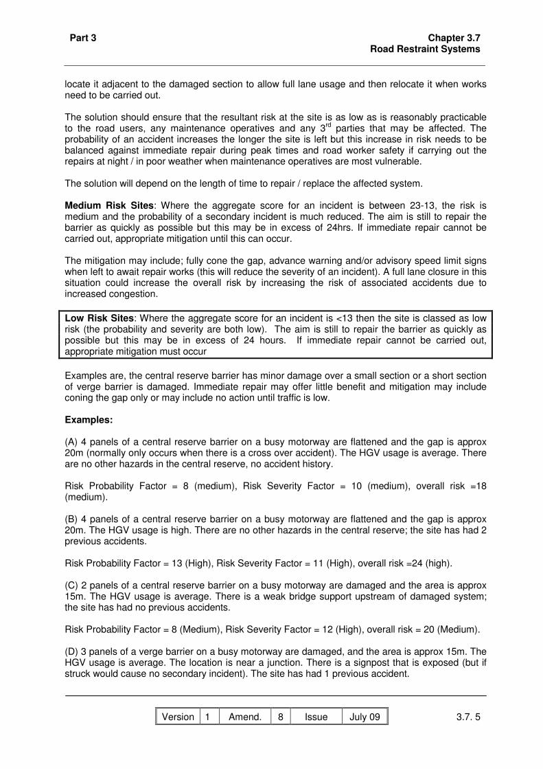
Part 3 Chapter 3.7 Road Restraint Systems
Version 1 Amend. No
8 Issue Date
July 09 3.7. 5
locate it adjacent to the damaged section to allow full lane usage and then relocate it when works need to be carried out. The solution should ensure that the resultant risk at the site is as low as is reasonably practicable to the road users, any maintenance operatives and any 3rd parties that may be affected. The probability of an accident increases the longer the site is left but this increase in risk needs to be balanced against immediate repair during peak times and road worker safety if carrying out the repairs at night / in poor weather when maintenance operatives are most vulnerable. The solution will depend on the length of time to repair / replace the affected system. Medium Risk Sites: Where the aggregate score for an incident is between 23-13, the risk is medium and the probability of a secondary incident is much reduced. The aim is still to repair the barrier as quickly as possible but this may be in excess of 24hrs. If immediate repair cannot be carried out, appropriate mitigation until this can occur. The mitigation may include; fully cone the gap, advance warning and/or advisory speed limit signs when left to await repair works (this will reduce the severity of an incident). A full lane closure in this situation could increase the overall risk by increasing the risk of associated accidents due to increased congestion. Low Risk Sites: Where the aggregate score for an incident is <13 then the site is classed as low risk (the probability and severity are both low). The aim is still to repair the barrier as quickly as possible but this may be in excess of 24 hours. If immediate repair cannot be carried out, appropriate mitigation must occur Examples are, the central reserve barrier has minor damage over a small section or a short section of verge barrier is damaged. Immediate repair may offer little benefit and mitigation may include coning the gap only or may include no action until traffic is low. Examples: (A) 4 panels of a central reserve barrier on a busy motorway are flattened and the gap is approx 20m (normally only occurs when there is a cross over accident). The HGV usage is average. There are no other hazards in the central reserve, no accident history. Risk Probability Factor = 8 (medium), Risk Severity Factor = 10 (medium), overall risk =18 (medium). (B) 4 panels of a central reserve barrier on a busy motorway are flattened and the gap is approx 20m. The HGV usage is high. There are no other hazards in the central reserve; the site has had 2 previous accidents. Risk Probability Factor = 13 (High), Risk Severity Factor = 11 (High), overall risk =24 (high). (C) 2 panels of a central reserve barrier on a busy motorway are damaged and the area is approx 15m. The HGV usage is average. There is a weak bridge support upstream of damaged system; the site has had no previous accidents. Risk Probability Factor = 8 (Medium), Risk Severity Factor = 12 (High), overall risk = 20 (Medium). (D) 3 panels of a verge barrier on a busy motorway are damaged, and the area is approx 15m. The HGV usage is average. The location is near a junction. There is a signpost that is exposed (but if struck would cause no secondary incident). The site has had 1 previous accident.
Part 3 Chapter 3.7 Road Restraint Systems
Version 1 Amend. No
8 Issue Date
July 09 3.7. 6
Risk Probability Factor = 12 (Medium), Risk Severity Factor = 6 (Medium), overall risk =18 (Medium). 3.7.4 Dealing with fluid & gas build-up in aluminium parapets Inspection and maintenance personnel may be exposed to a localised explosion risk due to the presence of hydrogen gas when drilling or dismantling an affected area. Inspections (2.12.3) will identify the location of potential sites and examine any posts that exhibit or have the potential to exhibit signs of pressure build-up e.g. wall bulging, blocked drainage holes, white fluid or horizontal cracks above the base plate. If a post exhibits any signs of pressure build-up it needs to be treated using an approved method unless it has been possible to safely clear the blocked drainage hole in the post above the weld line (3.5.3.2). It may be possible to safely drill at the base of the post using compressed air tools, suitable spark free equipment and PPE but in any event it will need to be carried out under an approved method statement. Posts that are found to be cracked must be replaced as soon as is reasonably possible with new posts incorporating correctly placed drainage holes (10mm diameter holes above the weld line, clear of the mortar bed). Details of the requirements for inspection and routine maintenance are contained in Chapters 2.12.3 and 3.5.3.2 and records must be reported to the Highways Agency Area Performance Manager.

Part 3 Chapter 3.8 Highways Agency Traffic Management Systems
Version 1 Amend. No
8 Issue Date
July 09 3.8. 1
3.8 Highways Agency Traffic Management Systems 3.8.1 General HATMS is a new term that embraces both the traditional systems associated with Police control offices along with other roadside technology used by the Regional Control Centres (RCCs) and National Traffic Control Centre (NTCC) for the provision of traffic information and traffic management. The term helps to distinguish these systems from the other ‘communication’ systems introduced during the RCC roll out (see below). The main roadside devices associated with HATMS are emergency roadside telephones (ERT’s),, signals, message signs, Motorway Incident Detection and Automatic Signalling (MIDAS), CCTV Cameras and Meteorological Outstations (there are currently two types of meteorological outstations, viz. fog detectors and anemometers). The MIDAS subsystem detects traffic conditions and automatically sets message signs and signals appropriately. The CCTV System provides dynamic images of the Highways Agency’s Core road network (in locations where it is available) into the RCC. It allows operators to switch and position cameras, as well as to view and set access priorities and restrictions for 3rd party users such as, Police Forces, media organisations and Local Authorities. 3.8.2 Maintenance Aspects The maintenance arrangements for HATMS vary significantly across the country. A list of the main technology systems covered and a top-level explanation of the different arrangements are given in this section. The local contractual arrangements will give details of the maintenance requirements for the area and these must be referred to. These, in turn, will likely refer to detailed requirements within the National Motorway Communications System (NMCS) documents which can be accessed at the Plans Registry website (www.tssplansregistry.org). A List of Drawings, Specifications and Instructions within the website are contained in the MCS206 document. Alternatively documents may be requested by post, fax or email. 3.8.3 Requirements for NTCC & TiS equipment The NTCC is operated by TiS Ltd (TiS) on behalf of the Highways Agency through a private finance initiative contract, which was awarded in March 2001 for a period of 10 years. Equipment which is owned and operated by TiS on the Highways Agency’s Network as part of this service include:
• Inductive Loops and Traffic Monitoring Units (TMU) • MIDAS • Automatic Number Plate Recognition (ANPR) cameras • National Motorway Communication System (NMCS) • Variable Message Signs (VMS) and Local Communications Controllers • TCC Interface (TCCI) and Video Access Control (VAC) Sub-system • CCTV Installations
Failure by others to maintain or replace faulty equipment may mean that the Highways Agency pays for a service which TiS are unable to deliver. Service Providers have obligations to help prevent such a situation occurring. In the event of any anticipated temporary or permanent loss of TiS equipment due to works carried out by or on behalf of the Service Provider (e.g. carriageway resurfacing that removes loop detectors; bridge parapet repairs requiring removal of ANPR cameras; traffic management that interferes or affects flow of traffic across TiS equipment) the Service Provider must provide at least one calendar month’s notice to NTCC and the relevant RCC of any such works and their expected impact

Part 3 Chapter 3.8 Highways Agency Traffic Management Systems
Version 1 Amend. No
8 Issue Date
July 09 3.8. 2
Contact details for notification of works to TiS is:
Head of Engineering 3 Ridgeway Quinton Business Park Quinton BIRMINGHAM B32 1AF NTCC Switchboard 0121 245 4800
Service Providers must allow for loop reinstatement costs in their works estimates and bid for funds accordingly. They must also replace loops in accordance with the relevant specification, obtainable from TiS. Further more they must allow for the costs of attendance by TiS to disconnect or reconnect loops plus an amount for each lane on which the loops are to be connected (£140 and £50 respectively at June 2006). 3.8.4 Regional Control Centres The Highways Agency has implemented a network of seven Regional Control Centres (RCCs) across England. The RCCs cover motorways and some key trunk roads within each region of the country. Over time their operations may be extended to the entire core network. The technology employed in the RCCs may be split into two types: - that employed to manage and control the roadside equipment in the RCC area (see NRTS below) and other technology used to provide communications with and manage the on-road resources of the Highways Agency Traffic Officer Service. The other technology systems include the Operational Telephony System, Airwave System, Integrated Communication Control System and the Command & Control System. The other technology systems are not further described here because the maintenance of these systems is handled by separate service level agreements which are handled at a National level. 3.8.5 TechMAC As well as the service providers described in the Introduction to this manual (e.g. MAC, EMAC, DBFO) there is also the TechMAC (Technology Maintaining (Managing) Agent / Contractor) Contract. This can provide an integrated technology network management, maintenance, renewal and improvement service for the technology associated with the strategic (core) motorway and trunk road network. 3.8.6 National Roads Telecommunications Services (NRTS) Following increasing demands on the NMCS communications network to support extra roadside devices and new systems and facilities, the NRTS initiative was conceived to provide a single, national approach to the future development of the telecommunications network and the provision of telecommunications services. The NRTS Contractor has full responsibility for the national telecommunications network and is responsible for providing a resilient and reliable service, and for monitoring the performance of telecommunications services. The Highways Agency appointed GeneSYS Telecommunications Ltd (GeneSYS) as its NRTS Contractor on 16th September 2005. They have responsibility for the telecommunications network for a period of 10 years. GeneSYS Co provides a “one stop shop” for the Highways Agency’s operational telecommunications needs. NRTS Co will gradually take on responsibility for the maintenance of the National Transmission network. Based on the new arrangements GeneSYS provides end-to-end responsibility for transmission services, while the responsibility for roadside devices and RCC applications remains with the

Part 3 Chapter 3.8 Highways Agency Traffic Management Systems
Version 1 Amend. No
8 Issue Date
July 09 3.8. 3
Highways Agency. This means GeneSYS are responsible for monitoring the performance of the transmission services, for providing a resilient and reliable service and for providing additional local connections to support additional roadside devices. From the Highways Agency’s perspective GeneSYS provide a service capability for conveying voice, video and data signals that link the Highways Agency’s roadside devices to the RCCs. NRTS separates the procurement of roadside communications services from road schemes. As part of their one-stop-shop approach, GeneSYS provide services based on a fixed price catalogue, while looking at the effects of individual projects on the telecommunications network as a whole. This allows scheme consultants to budget with certainty of price and allows GeneSYS to design changes so as to optimise the network capacity strategically. 3.8.7 Design and installation of the telecommunications network by GeneSYS Smaller Schemes (LNMS) and Technology Schemes may have an effect upon the telecommunications network. Service Providers may act as designer to develop these schemes and contractor to implement them so should be aware of the responsibilities held by GeneSYS relating to the telecommunication network and explained below. 3.8.7.1 Transmission Design GeneSYS works collaboratively with scheme designers from initial conception. They will provide advice on transmission routing, capacity planning and pricing. GeneSYS are responsible for designing cabling and transmission equipment between standard demarcation points, termed Service Delivery Points (SDPs). For roadside devices the SDP is generally in the cabinet alongside the roadside device. A standard list of prices for the transmission elements of schemes and definition of SDPs is available from GeneSYS. Service Providers must contact GeneSYS at the earliest opportunity for any schemes, for which they have responsibility, which either require new services, or alterations to transmission services, or will affect any aspect of the Highways Agency’s transmission network. 3.8.7.2 Transmission Installation GeneSYS is responsible for the installation and testing of cabling and transmission equipment for all schemes up to the SDPs. 3.8.7.3 Civils Infrastructure Detailed design and installation of telecommunications ducts, chambers, ducts through structures, cross carriageway ducts and transmission stations may be carried our by GeneSYS or the Service Provider (as designer / contractor). Design and installation must be in accordance with the NRTS standards, available from GeneSYS. 3.8.7.4 End devices Responsibility for the design, connection and installation of end devices to SDPs remains with the scheme contractor. Such end devices typically includes signals, VMS, MIDAS detectors, ERTs and CCTV cameras.

Part 3 Chapter 3.8 Highways Agency Traffic Management Systems
Version 1 Amend. No
8 Issue Date
July 09 3.8. 4
3.8.7.5 Maintenance / installation affecting Transmission Network Service Providers must obtain agreement from GeneSYS prior to undertaking any maintenance / installation works which may affect the Highways Agency’s transmission network. 3.8.7.6 GeneSYS contact details
Contact details for GeneSYS are:
GeneSYS Telecommunications Ltd 9 Ridgeway Quinton Business Park BIRMINGHAM B32 1AF GeneSYS Helpdesk Tel: 0845 603 2239 (24 Hours) Fax: 0121 506 6120 E-mail [email protected]
Contact details for Regional Managers may be obtained from the GeneSYS helpdesk.
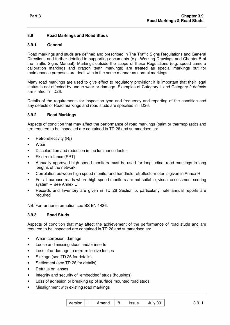
Part 3 Chapter 3.9 Road Markings & Road Studs
Version 1 Amend. No
8 Issue Date
July 09 3.9. 1
3.9 Road Markings and Road Studs 3.9.1 General Road markings and studs are defined and prescribed in The Traffic Signs Regulations and General Directions and further detailed in supporting documents (e.g. Working Drawings and Chapter 5 of the Traffic Signs Manual). Markings outside the scope of these Regulations (e.g. speed camera calibration markings and dragon teeth markings) are treated as special markings but for maintenance purposes are dealt with in the same manner as normal markings. Many road markings are used to give effect to regulatory provision; it is important that their legal status is not affected by undue wear or damage. Examples of Category 1 and Category 2 defects are stated in TD26. Details of the requirements for inspection type and frequency and reporting of the condition and any defects of Road markings and road studs are specified in TD26. 3.9.2 Road Markings Aspects of condition that may affect the performance of road markings (paint or thermoplastic) and are required to be inspected are contained in TD 26 and summarised as: • Retroreflectivity (RL) • Wear • Discoloration and reduction in the luminance factor • Skid resistance (SRT) • Annually approved high speed monitors must be used for longitudinal road markings in long
lengths of the network • Correlation between high speed monitor and handheld retroflectormeter is given in Annex H • For all-purpose roads where high speed monitors are not suitable, visual assessment scoring
system – see Annex C • Records and Inventory are given in TD 26 Section 5, particularly note annual reports are
required NB: For further information see BS EN 1436. 3.9.3 Road Studs Aspects of condition that may affect the achievement of the performance of road studs and are required to be inspected are contained in TD 26 and summarised as: • Wear, corrosion, damage • Loose and missing studs and/or inserts • Loss of or damage to retro-reflective lenses • Sinkage (see TD 26 for details) • Settlement (see TD 26 for details) • Detritus on lenses • Integrity and security of “embedded” studs (housings) • Loss of adhesion or breaking up of surface mounted road studs • Misalignment with existing road markings

Part 3 Chapter 3.9 Road Markings & Road Studs
Version 1 Amend. No
8 Issue Date
July 09 3.9. 2
• Studs that do not meet the requirements for luminous intensity • Studs that do not meet the requirements for reflective conspicuity. • Records and Inventory are given in TD 26 Section 5, particularly note annual reports are
required

Part 3 Chapter 3.10 Road Traffic Signs
Version 1 Amend. No
8 Issue Date
July 09 3.10. 1
3.10 Road Traffic Signs 3.10.1 General The Standards and full advice for maintenance of road traffic signs installations are contained in TD25. Statutory requirements for signs, including the removal of temporary signs, are stated in the Traffic Signs Regulations and General Directions. Many signs are required to be lit and their legal status is affected if the illumination has failed. It is important that such failures are detected and rectified promptly. Aspects of condition that may affect the performance of road traffic signs are contained in TD 25 and summarised as: • Visual performance, electrical safety and operation and structural integrity • General cleaning of signs • Incorrect orientation, damaged or missing • Loss of surface/paint/legend from peeling, damage or vandalism • Reduction in the retro-reflectivity of white sign face materials • Degradation of coloured sign face materials • Lamp failure, lamp on during the day, photo-electric circuit or time switch failure, electricity
supply failure, no fuse, lamp dirty or output low • Moving parts of secret and variable message signs malfunction – see MCH 1553 • Wiring deterioration, discontinuity of protective conductors, earth electrode failure, earth loop
impedance failure, inadequate insulation resistance, missing drawings, condition of sealant, polarity failure, residual current device failure.
• Wiring in hazardous condition • Access for maintenance blocked or security of the equipment breached • Corrosion/deterioration or damage to plate, fittings, frame or post • Records and Inventory are given in Chapter 7, particularly note annual reports are required
Details of the requirements for the maintenance of traffic signs with dew resistant coatings is shown in section 3.10.2 below. 3.10.2 Maintenance of Traffic Signs with Dew & Graffiti Resistant Coatings Traffic signs with dew resistant coatings must be maintained in accordance with the requirements of IAN 56/04. 3.10.2.1 Required Action Contractors responsible for cleaning traffic signs must ensure that under no circumstances detergents, abrasive sponges, high pressure water jet or brushes be used to clean sings with dew resistant coatings. When such signs require cleaning only clean water from a low pressure hose must be used. Signs with dew resistant coatings are unlikely to require cleaning as frequently as other signs.

Part 3 Chapter 3.10 Road Traffic Signs
Version 1 Amend. No
8 Issue Date
July 09 3.10. 2
3.10.2.2 Traffic Signs with Dew & Graffiti Resistant Coatings There are two types of sign face with dew resistant coatings; one supplied by 3M UK plc and the other by Rennicks (UK) Ltd. The signs are identifiable by a label on the rear of the sign that reads: Warning: Sign face coated with self cleansing dew resistant overlay & should not require cleaning.

Part 3 Chapter 3.11 Road Traffic Signals
Version 1 Amend. No
8 Issue Date
July 09 3.11. 1
3.11 Road Traffic Signals 3.11.1 General The standards currently utilised for maintenance of road traffic signal installations are detailed in TD 24 and TA84. Statutory requirements for signals are stated in TSRGD. Reference should also be made to the Guidance on signal head optics for advice in connection with light source replacement and innovation. During emergencies or incidents it may be necessary to reduce response times. There may be instances where the maintenance of traffic signals on the network is not the responsibility of the Service Provider, but an adjacent highway authority. The responsibility for such maintenance must always be clarified. There will be occasions when a failure of a set of signals, whilst not sufficient to invoke a full scale emergency, may cause significant problems. In order for such incidents to be dealt with effectively the Service Provider must develop a ‘Traffic Signal Failure Plan’. This plan will detail the Service Provider's actions to mitigate the effects of the failure during the hazard mitigation period in order to maintain a reasonable flow of traffic through any junction until such time as the permanent repair is carried out. Aspects of condition that may affect the achievement of the performance requirements for road traffic signals are contained in TD24 and TA84 and summarised as: • Signal failure • Operation of signal heads, control equipment, detectors, dimmer, push buttons, indicator
lamps and audible and tactile signals • Alignment, cleanliness and visibility of the signal head, including obstruction by trees or other
vegetation • Physical condition of poles, signal heads, support brackets and backing boards. • Condition of any regulatory and variable message sign/illumination • Equipment wiring and earth condition • Condition and accessibility of equipment cabinets • Data sheets and logbooks present in cabinet • Damage to traffic signals and counter / loops, due to vandalism, road traffic accident damage,
or excavation by Service Provider or Statutory Undertaker • Hazards, including the presence of gas and difficulty in accessing the cabinet

Part 3 Chapter 3.12 Lighting
Version 1 Amend. No
8 Issue Date
July 09 3.12. 1
3.12 Lighting 3.12.1 General The requirements for maintenance of lighting installations are covered by TD23 Trunk Roads and Trunk Road Motorways Inspection and Maintenance of Road Lighting. The suite of standards currently utilised for design and operation of road lighting installations incorporate the above standard and typically also include: • TA49 Appraisal of New and Replacement Lighting on Trunk Roads and Trunk Road
Motorways • TD34 Design of Road Lighting, linked to BS 5489 and technical reports issued by the
Institution of Lighting Engineers (ILE). • BS 767I. I.E.E. Regulations. Requirement for Electrical Installations (Wiring Regulations). • Other guidelines and recommendations, for example from the Association of Street Lighting &
Electrical Contractors (ASLEC), are also incorporated into the maintenance regimes. • Other design codes may also be included. • TA89 Use of Passively Safe Signposts, Lighting Columns and Traffic Signal Posts to BS EN
12767 • TA96 Whole Life Cycle Code of Practice for Road Lighting (to be published in 2007) In general, lamp replacement maintains safety, service and value for money. However, other aspects will need to be considered to ensure that overall (whole life) maintenance costs are minimised. • Standardisation of components, where possible, to minimise the number of different
components of different manufacture and types are used. • Replacement and repair materials and equipment should have the same physical, photometric
and aesthetic characteristics as existing, except where the existing is obsolete or due for replacement.
• Lights are maintained in a way that enables a continuing rapid and economic maintenance response including replacement of power factor correction capacitors.
• Lamps containing materials that can be recycled should be utilised with an aim of achieving 70% recycling. Additionally, mercury free lamps should also be used where practicable. The minimum requirements shall be full compliance with the Waste Electrical and Electronic Equipment Directive (WEEED)
Aspects of condition that may affect the achievement of the performance requirements for Lighting can be summarised as: • Lamp failure, photoelectric circuit or time switch failure, electricity supply failure, lamp damage • Lamp output low due to lamp being dirty, lamp ageing, voltage drop • Lamp on during day due to photoelectric circuit or time switch failure • Obscuring by foliage, or other signs and structures • Incorrect orientation of the lamp due to damaged or misaligned mountings • Wiring deterioration, discontinuity of protective conductors, earth electrode failure, earth loop
impedance failure, inadequate insulation resistance, condition of sealant, polarity failure, protective current device failure, thermostat or heater failure,
• Wiring in hazardous condition • Access for maintenance blocked or security of equipment breached • Deterioration or damage to column, brackets or other supports - corrosion, damage or missing
parts that affect function or promote deterioration Specific guidance on defects, their categorisation and response times may be found in TD23.

Part 3 Chapter 3.13 Soft Estate
Version 1 Amend. No
8 Issue Date
July 09 3.13. 1
3.13 Soft Estate 3.13.1 General The soft estate is defined as: The natural part of the highway estate including any cultural heritage assets together with hard landscaping areas (as opposed to engineering/operational part of the highway including structures, carriageway, hard shoulder and central reserve that may be constructed with concrete, bituminous materials, steel, etc.). For a list of element descriptions refer to DMRB Volume 10. In addition to the general advice indicated below, reference should be made to Volumes 10 and 11 of the DMRB, IAN’s 76/06 to 82/06, IAN 84/07 EnvIS, IAN 100/07 Cultural Heritage Management Plans, the current Highways Agency’s Biodiversity Action Plan, the Highways Agency’s Landscape Management Handbook HA108. Examples of aspects of condition that may affect the achievement of the performance requirements for the soft estate are: • Vegetation that restricts visibility along sight lines at junctions and access points and below
minimum stopping distances at bends • Vegetation that obstructs the view of signs, lights, signals and marker posts • Vegetation that restricts access to off-carriageway refuges for road users and service
providers (historically maintained by undertaking a swathe cut) • Vegetation that restricts access to emergency roadside telephones • Vegetation (particularly gorse) that creates a fire hazard • The presence of unsafe trees within Area Network or within falling distance of the highway
boundary • The presence of undesired vegetation in hardened areas • The presence of Injurious weeds • Damage to or deterioration of protected named species and habitats • Damage to or deterioration of special ecological measures (e.g. deer fencing, badger tunnels
and bat boxes) • Deterioration of grasslands and associated bulb planting • Deterioration of hedgerows • Deterioration of wetlands • Deterioration of woodland/trees/shrubs including any associated herbaceous planting • Deterioration of the cultural heritage asset Routine Maintenance of the soft estate includes those operations which are required to maintain the soft estate asset in line with its element objectives and are usually carried out on a cyclical basis. These are more servicing than repair activities. Examples include: • thinning, coppicing , pollarding of woody areas to maintain them as woody areas including any
follow up operations associated with these such as applying herbicides to cut stumps or treatment of arisings
• cleaning of woody areas by removing competing woody vegetation including treatment of any arisings
• trimming hedges

Part 3 Chapter 3.13 Soft Estate
Version 1 Amend. No
8 Issue Date
July 09 3.13. 2
• arboricultural works to trees to maintain the health and therefore safety of the tree, may also include works to make sure tree does not hinder operation of network, or to avoid nuisance to our neighbours,
• cutting/mowing/raking of grassland, to maintain it as grassland • removal of scrub, gorse and trees including clear felling from grassland to maintain it as
grassland including any follow up operations associated with these such as applying herbicides to cut stumps or treatment of arisings
• removal of vegetation from a rock face to maintain it as an open rock face • ditch cleaning to maintain original profile of ditch to maintain drainage capability • maintenance of other water bodies by removing vegetation, silt and other debris which
conflicts with element objective • maintenance of existing wild life fences, badgers/otters • Removal of litter. • Removal of injurious and noxious weeds • Grass cutting for safety requirements, to maintain visibility to signs and access to street
furniture. Improvement to the Soft Estate includes those operations that add value to the soft estate asset by changing the element objective or which enhance areas by adding something to enable the objectives to be more effectively met. They are more repair or new operations ( This would include any additions asked for by third parties and agreed to by the HA). Examples include:
• New tree and shrub planting for landscape/biodiversity reasons. • Introducing new woody/herbaceous planting into existing woodland to add species and
structural diversity or improve screening performance. This should be combined to immediately follow thinning/or clear felling operations. The first 5 years of aftercare for any new planting would be regarded as part of the Improvement i.e. weeding and beat up)
• adding a otter ledge • adding new wildlife fencing for Otter deer badgers • adding new dormice or bat boxes • Adding wildflower seeding/plug planting into grassland. • Adding bulbs into grassland or woodland • Creating new waterbodies, either for drainage or conservation reasons The Service Provider is reminded that any work to the soft estate is highly likely to encounter the presence of protected species (flora and fauna) which may require licenses to be in place before work can start and that appropriate advice must be sought from an ecologist or the Highways Agency’s SSR Regional Environmental Advisor, before commencing work. It is likely that if found prior assessment work and licences may be required to undertake the work.
3.13.2 Access Access to boundary fences for inspection and maintenance must be kept clear at all times.

Part 3 Chapter 3.13 Soft Estate
Version 1 Amend. No
8 Issue Date
July 09 3.13. 3
3.13.3 Woodlands, Trees & Hedgerows Management of trees, woodlands and hedgerows must be planned to ensure these elements fulfil their objectives and functions as defined in the DMRB Volume 10, Section 0, and as set out in the appropriate landscape management plan. Trees are an important amenity feature of the roadside soft estate and their contribution to the environment is such that they must be retained wherever it is safe to do so. Highway trees do however have the potential to pose a threat to the safety of road users, pedestrians and to adjoining property and livestock. Any external signs of decay or deterioration must be reported by the inspector for action by a qualified arboriculturist. Trees that lie within falling distance of the highway boundary but located outside the highway boundary and not in the ownership of the Service Manager are classified as highway trees as described in Section 154 , Highways Act 1980. If such trees are found to be in an unsafe condition the Service Manager has the power to order the owner to carry out such work as may be necessary to make the tree safe. If this is not carried out by the owner within 14 days, the Service Manager has the power, in accord with the provisions of Section 154 of the 1980 Highways Act, to carry out the work and recharge the cost of the work to the owner. However, trees beyond the highway boundary may be subject to tree preservation orders (TPO). In these situations The Highways Act 1980 may not apply and planning permission may need to be sought to remove the tree; discussion with the appropriate Local Authority Tree Officer must be undertaken. Qualified arboriculturists must be employed by the Service Provider to carry out specialist inspections and to advise on signs of ill health or damage to trees. Care must be taken to ensure the appropriate maintenance of ‘veteran trees’ (trees that are of interest biologically, aesthetically, or culturally because of their age). The following contain guidance about working close to trees: BS5837 (1991) Guide for trees in relation to construction. NJUG 10 Guidelines for the planning, installation and maintenance of utility services in proximity to trees. The removal of hedgerows, particularly important hedgerows as defined by the Hedgerow Regulations 1997, is likely to be subject to a requirement for planning permission outside of the soft estate to the equivalent (ROD) within the soft estate. The removal of hedgerows is also contrary to government planning advice PPS9 and therefore must be avoided wherever possible. Removal will only be considered under exceptional circumstances and subject to expert ecological assessment. 3.13.4 Grasslands Cutting of grasslands that are cut for visibility and safety must be undertaken to ensure that standards for visibility and sightlines, and safe off-carriageway refuges including access to emergency road side telephones, are maintained. Non-visibility grasslands are an equally important feature of the network and will need to be managed to ensure these elements fulfil their functions and objectives as defined in DMRB Volume 10, Section 0, and as set out in the appropriate landscape management plan for the route. Failure to manage these grasslands will mean their function or objective will change with the succession to scrub invasion and then woodland which will increase the network’s tree stock which will in turn increase maintenance costs.

Part 3 Chapter 3.13 Soft Estate
Version 1 Amend. No
8 Issue Date
July 09 3.13. 4
3.13.5 Conservation Wetlands These are defined as those water bodies which have no drainage or attenuation functions. Conservation water bodies need to be managed by the Service Provider to ensure these elements fulfil their objectives and functions as defined in the DMRB Volume 10, Section 0, and as set out in the appropriate landscape management plan. 3.13.6 Weeds Control of notifiable weeds (sensu The Weeds Act 1959 HMSO) may be necessary. It is an offence under the Wildlife and Countryside Act 1981 HMSO to cause Japanese Knotweed (Polygonum cuspidatum) or Giant Hogweed (Heracleum mantegazzianum) to grow in the wild. Care must be taken during the transport of soil or other material, which may contain parts or seeds of these plants, from one place to another as such activities may infringe this legislation. 3.13.6.1 Common Ragwort Common Ragwort (Senecio jacobaea) is a widespread weed found on roadside verges, waste ground, and neglected pasture. It is one of five “injurious” weed species proscribed in the Weeds Act 1959. Where these weeds occur the Act requires occupiers of land to undertake measures to control their spread. The Ragwort Control Act inserts a new provision into the Weeds Act 1959 enabling the Minister to make a code of practice on how to prevent the spread of Common Ragwort. A code of practice is currently available on the DEFRA website (see other sources of information below) and contains very useful advice including identification of risk in order to prioritise control measures. The tissues of Ragwort contain pyrrolizidine alkaloids, which are highly toxic to grazing animals, particularly cattle and horses and to a lesser extent sheep and goats. Ragwort poisoning is cumulative and results in liver failure and is usually fatal to animals that ingest it. It remains poisonous in its dried state and animals are frequently poisoned when they eat hay and silage containing it. Ragwort is a biennial plant germinating in summer and autumn and forming a tight rosette of leaves before going on to flowering and seeding the following year. After seeding the plant dies. It produces heads of bright yellow daisy like flowers from late May into August, each plant producing several thousand wind borne seeds which can spread over a considerable area. Seed can remain viable in the soil for up to 20 years. The Service Provider must be proactive in controlling injurious weeds. Total eradication of Ragwort is not a realistic option given the ease with which highway verges can be re-infested from neighbouring land or from dormant seeds in the soil. It is recommended that within a treatment programme those areas where infestations are close to livestock or where they are heavy be dealt with first. There are a number of measures which can be used in combination to provide adequate control: • Regular mowing: to prevent flowering (in many instances this will not be acceptable on nature
conservation grounds).

Part 3 Chapter 3.13 Soft Estate
Version 1 Amend. No
8 Issue Date
July 09 3.13. 5
• Hand pulling: generally this is the only effective method to control the weed once the plants have started to flower (at this stage they are easy to find). It must be carried out before seed has dispersed. This is a very labour intensive and therefore expensive and operatives must wear protective clothing, currently little is known about the entry of the alkaloid through the human skin. Pulled plants must be removed from site for appropriate disposal (DEFRA Code of Practice to ‘Prevent and Control the Spread of Ragwort’ gives good guidance on disposal).
• Spot treatment with selective herbicide spray (selective weed killers act on broad leaved plants
only and leave grasses unaffected). There are a number of selective herbicide formulations that provide effective control of Ragwort but they generally need to be applied before the plant shows any colour in its flowers otherwise they continue to set and disperse viable seed. Treatment is best carried out in spring through to early summer depending to some extent on regional location. Timely herbicide application will greatly reduce the amount of hand pulling required. Care is needed to ensure that spray drift does not damage adjoining land or other broad-leaved plants such as trees and wildflowers within the highway soft estate.
• Spot spray treatment can also be carried with a formulation of citronella oil and this substance
can be used to treat rosettes over a long period. Because of its formulation this material is likely to be less economical on large infestations but it may be considered to extend the period of treatment into the winter months when selective herbicides are not effective.
Service Providers can get further advice from Highways Agency Network Services regional environmental advisors. Information on ragwort and other injurious weeds, including the Code of Practice on how to prevent the spread of ragwort, may be found on the DEFRA Website. 3.13.6.2 Control of Other Injurious Weeds In addition to Ragwort the Weeds Act 1959 also lists Spear Thistle (Cirsium vulgare), Creeping Thistle(Cirsium arvense), Broad Leaved Dock (Rumex obtusifolius) and Curled Dock (Rumex crispus) which must be controlled. These are likely to be widespread on the highway estate. Hand pulling is not an option for these species but they can all be effectively controlled by spot treatment with selective herbicide, or in exceptional circumstances by a carefully targeted application of an appropriate contact translocated herbicide. Under Section 14 Schedule 9 of the Wildlife and Countryside Act 1981 it is also an offence to cause the spread of Japanese Knotweed (Fallopia japonica) and Giant Hogweed (Heracleum mantegazzianum). These problem weeds occur on the highway estate but are much more localised. A concerted programme of translocated herbicide applications can effectively control them. It must be remembered that Japanese Knotweed, and soil containing it, is classed as “controlled waste” and under the Environmental Protection Act 1990 must be disposed of safely to a licensed landfill site. The presence of this weed on highway verges can put severe constraints on engineering and maintenance operations particularly any work that involves trenching or other form of excavation. Material containing the weed must not be moved within a site. Service Managers can get further advice from SSR regional environmental advisors.

Part 3 Chapter 3.13 Soft Estate
Version 1 Amend. No
8 Issue Date
July 09 3.13. 6
3.13.7 Cultural Heritage Asset Trunk roads and their environs contain areas of considerable value for cultural heritage. Cultural heritage assets potentially affected by roads include buried remains, historic structures and historic landscapes. The guidance for Service Providers in managing these assets are set out in IAN 100/07 Cultural Heritage Management Plans. Additionally the requirements for recording these assets are included within the EnvIS system as introduced by IAN 84/07 and detailed at 2.15 of this Network Management Manual.

Part 3 Chapter 3.14 Sweeping & Cleaning
Version 1 Amend. No
8 Issue Date
July 09 3.14. 1
3.14 Sweeping and Cleaning 3.14.1 General The requirements of this chapter relate to the responsibilities in respect to Section 89 of the Environmental Protection Act 1990 (EPA) to ensure that the highway is, so far as is practicable, kept clean and to ensure that the land, so far as is practicable, kept clear of litter and refuse. The Secretary of State has the duty for litter and refuse on the motorway and those APTR that have been transferred back to the Secretary of State under Section 86(11) of the EPA (see Section 3.16), whilst local authorities are responsible for cleaning and removal of litter from all other APTR. The Service Provider is responsible for discharging these responsibilities on behalf of the Secretary of State in respect of the network and in doing so must maintain the network clear of litter and refuse and in a state of cleanliness as recommended in the Environmental Protection Act 1990: Code of Practice on Litter and Refuse (Department of Environment, Food and Rural Affairs). This relates to the sweeping and cleaning of all channels and hard shoulders, clearing and removal of debris from traffic lanes, hard shoulders, verges and central reservations, removal of litter, and footway and cycle track sweeping. This code of practice, which can be downloaded from the internet, seeks to encourage duty bodies, those with duties imposed by the EPA to maintain their land within acceptable cleanliness standards with the emphasis being on consistent and appropriate management to keep it clean rather than how often it is cleaned. It details four grades of cleanliness for which the Code defines the performance requirements. The EPA does not contain anything that removes the responsibility of the Highways Agency to keep trunk roads safe for the travelling public. There will, therefore, be a continuing need for sweeping to be carried out by the Highways Agency's Service Providers (e.g. dealing with shed loads, spillages and accident debris). 3.14.2 Meeting the Performance Requirements The Service Provider must adopt a proactive approach to the removal of litter and other debris from the Network in order to meet the Performance Requirements. This may be achieved using a combination of programmed scavenges, as need dictates, together with "black spot" scavenges as required in specific locations where the highway has become heavily littered as a result of other factors such as debris from vehicles or wind blown litter. If a particular source of regular litter, wind blown or otherwise, can be identified then those responsible should be requested to exercise control of their site more effectively. Such requests must be documented. On occasions it will be necessary for emergency vehicles to drive along the hard shoulder, often at speed. It has been noted that debris on the hard shoulder, particularly metal objects can cause punctures to emergency vehicles. Therefore the use of magnetic cleaning is encouraged. Weed and vegetation growth that is likely to obstruct the flow of water in channels or cause structural deterioration, does not fall within the scope of the EPA. Such growth must be treated in accordance with the appropriate standards. The Highways Agency’s policy is that litterbins are provided only at designated picnic sites and those lay-bys with toilets and/or picnic tables. Those sites must be scavenged as necessary.

Part 3 Chapter 3.14 Sweeping & Cleaning
Version 1 Amend. No
8 Issue Date
July 09 3.14. 2
Examples of condition that are likely to prevent the achievement of the Performance Requirements include: • Detritus, litter, refuse, animal carcasses, debris and other objects on the Network • Growth of grass or other vegetation between the channel and kerb, which is likely to obstruct
the flow of water or cause structural deterioration.

Part 3 Chapter 3.15 Fences, Walls, Screens & Environmental Barriers
Version 1 Amend. No
8 Issue Date
July 09 3.15. 1
3.15 Fences, Walls, Screens and Environmental Barriers 3.15.1 General There is a need to maintain a record of the purpose of fences, walls, screens and environmental barriers, so that their performance can be verified as required by the EnvIS system. The intended design and performance requirements may be described in the original contract documentation. Aspects of condition that my affect the achievement of the performance requirements for fences, walls, screens and environmental barriers are: • Rotten wooden elements that affects function or promotes deterioration • Corroded metal that affects function or promotes deterioration • Concrete cracking, spalling or reinforcement corrosion that affects the function or promotes
deterioration • Brickwork cracking, spalling or loss or mortar that affects the function • Missing, broken, deformed or cracked components that affect function or promote
deterioration • Loose nuts, bolts and other components may represent a hazard or promote deterioration • Lack of tension in a strained wire fence • Too low fence or barrier (caused by subsidence or otherwise) • Loss of paint, galvanising or other protective system • Effects of spray and pollutants degrading colour or transparency The appearance of fences, walls, screens and environmental barriers is important and any repairs or replacement sections must maintain the uniformity of their appearance, unless the existing is obsolete. On all-purpose trunk roads the decision to fence land rests with the owner and occupier of the land fronting on to the highway, although in most locations he will be liable for negligence if damage is caused by his animals straying on to the highway. The Highways Agency has no general obligation to fence off the highways to which there is a public right of access, although there is power to fence highways in Section 80, as modified, of the Highways Act 1980. Any fencing along the boundaries of APTR is therefore generally the responsibility of the adjoining landowner/user following any agreed maintenance period after installation on new schemes. In some circumstances however, fencing for the protection of wildlife may remain the property of the Highways Agency. Because of their special status restricting general access, and high-speed characteristics, motorways need to be fenced to avoid the hazard to traffic presented by trespassers and wandering animals. It is the Highways Agency's practice to accept responsibility for the construction or erection and maintenance of the fencing along the motorway boundaries. This does not, however, absolve the adjoining landowner/occupier from the statutory obligations under the Animals Act 1971 to prevent stock from straying. Although it is the Highways Agency's practice to provide and maintain adequate fencing, the Highways Agency does not accept responsibility for alterations to the fence necessitated by adjoining landowners/occupiers changing requirements after installation. In those circumstances it is for the landowners/occupiers to provide and maintain any additional rails/netting/wire needed to prevent the egress of animals on to the highway.

Part 3 Chapter 3.15 Fences, Walls, Screens & Environmental Barriers
Version 1 Amend. No
8 Issue Date
July 09 3.15. 2
In the interests of safety, Service Providers are expected to use discretion in carrying out minor/temporary repairs on any part of the fence added by the landowner/occupier, where such parts are found to be defective as a result of inspection, or reports from the Police or public. Serious defects will need to be reported to the landowner/occupier with a request for them to be rectified. If the repairs need to be carried out immediately, in the interests of safety, the Service Provider will carry out the necessary work and make a request to the landowner/occupier for reimbursement of any substantial expenditure incurred. Where a spate of wildlife casualties are identified on the road and in areas which fencing provisions for wildlife have already been made, the fencing in this area must be immediately inspected to identify defects with or damage to the fencing. This must be repaired immediately as appropriate to prevent further casualties. This is important from an animal welfare and road user safety perspective. Fences designed for other special purposes, such as the security of goods or the protection of traffic from sporting activities, and installed by the owners on land adjoining a motorway, remain the responsibility of the landowner/occupier, and any serious defects must be drawn to the attention of the owner/occupier. Where there is persistent vandalism and theft, consideration should be given to replacing the existing fence with a more substantial type, e.g. replace timber post & rail with palisade.

Part 3 Chapter 3.16 Retained Litter Clearing Duties
Version 1 Amend. No
8 Issue Date
July 09 3.16. 1
3.16 Retained Litter Clearing Duties 3.16.1 General Section 3.14 details the requirements for sweeping and cleaning to fulfil the requirements of Section 89 of the Environmental Protection Act 1990. The Secretary of State has responsibility for fulfilling the requirements on the motorway network and local authorities typically have responsibility for sweeping and clearing of APTR. Section 86(11) of the Act allows the Secretary of State to transfer responsibilities from the local authority to the highway or road authority. This chapter details those sections of road where the Secretary of State has exercised this power. Tables 3.16.1 and 3.16.2 below detail those sections of APTR for which the Secretary of State retains the responsibility for sweeping and cleaning. The Service Provider, under the terms of his contract is responsible for discharging responsibilities arising from the EPA on behalf of the Secretary of State for those roads listed in Table 3,16.1 where they form part of the Network.
Road No. Description A2 From its junction with the M2 Motorway (Junction 1) to its junction with the M25
Motorway (Junction 2). A282 From its junction with the M25 Motorway (Junction 30) to its junction with the M25
Motorway (Junction 2). A27 From the southern end of the A3(M) to its junction with the M27 Motorway (Junction
13). A40(M) From its junction with the A40 trunk road (Westway) to its junction with the A5
Edgware Road. A56 From its junction with the M66 Motorway to its junction with the M65 Motorway
(Junction 8). A5103 From its junction with the M56 Motorway (Junction 3) to its junction with the M63
Motorway (Junction 9).
Table 3.16.1 All-Purpose Trunk Roads with Retained Litter Clearing Duties Table 3.16.2 details those sections of road contained within Design Build Finance and Operate (DBFO) contracts for which the Highways Agency has contracted out the sweeping and cleaning of these roads to the DBFO concessionaire. The Service Provider, under the terms of his contract is responsible for discharging responsibilities arising from the EPA on behalf of the Secretary of State for those roads listed in Table 3,16.2 where they form part of the Network.
Road No. Description A1 From a point 350 metres south of its junction with the Great North Road at
Alconbury to a point 280 metres north of the Fletton Parkway Interchange. A1 From a point 520 metres south of the Old Great North Road at Micklefield to a
point 1 kilometre north of the A64(T) Leeds Road. A14 From a point 420 metres south east of its junction with Rusts Lane to its junction
with the A1 trunk road. A19 From its junction with the A168 road at Thirsk to the roundabout at the junction with
the A185 county road immediately south of the southern entrance to the Tyne Tunnel.

Part 3 Chapter 3.16 Retained Litter Clearing Duties
Version 1 Amend. No
8 Issue Date
July 09 3.16. 2
Road No. Description A30 From its junction with the M5 Motorway (Junction 29) to its junction with the A35
trunk road at Honiton. A35 From its junction with the A30 trunk road at Honiton to the western leg of the
roundabout at the junction of A35 and A31 trunk roads north east of Bere Regis. A50 From the boundary between the City of Stoke on Trent and the Borough of Stafford
at the junction with the A521 county road to the junction with the A516 trunk road. A66 From its junction with the A19 trunk road to a point 265 metres east of the
overbridge to Teeside Retail Park in Stockton on Tees Borough Council. A69 From its junction with the M6 Motorway (Junction 43) to its junction with the A1
trunk road (West Road Interchange). A168 From a point 350 metres east of the county road overbridge located 650 metres
east of the A1(M) bridge over the eastbound carriageway of the A168 trunk road at Dishforth to its junction with A19 trunk road at Thirsk.
A174 From its junction with the A19 trunk road at Parkway Interchange to the junction with the A1053 trunk road.
A417 From its junction with the A419 trunk road to the grade separated junction at Ordnance Survey Grid Reference 388500E, 217600N near M5 (Junction 11a).
A419 From its junction with the M4 Motorway (Junction 15) to its junction with the A417 trunk road.
A1053 From its junction with the A174 trunk road to its junction with the A1085 county road at Grangetown.
Table 3.16.2 All-Purpose Trunk Roads with Retained Litter Clearing Duties contracted to
DBFO concessionaires 3.16.2 Inspection Requirements No detailed inspections will be carried out and reliance must be placed on the regular Safety inspections and Safety Patrols (see Part 3.1) to decide when any special action needs to be taken.

Part 3 Chapter 3.17 The Landfill Directive and Liquid Waste
Version 1 Amend. No
8 Issue Date
July 09 3.17. 1
3.17 The Landfill Directive and Liquid Waste 3.17.1 Purpose The purpose of this chapter is to update area teams and Service providers on the implications of the Landfill Directive on the disposal of liquid wastes arising from the highway network and offers guidance on best practice disposal and recovery methods. 3.17.2 Background The Landfill Directive was implemented in 2002 with the aim of reducing the negative impacts of landfill. The main changes to landfill practices included: • The categorisation of landfill sites as hazardous, non-hazardous or inert. • The requirement for pre-treatment of all wastes destined for landfill. • The progressive diversion of biodegradable waste from landfill. • The complete banning of liquid waste from landfill The banning of liquid waste from landfill is of primary concern to highway maintenance contractors. Liquid waste is defined in the Landfill Directive Interpretation Note 1 (Environment Agency, July 2002), included at Annex 3.17.1, as: • “Any waste that near instantaneously flows into an indentation void made in the surface of
the waste, • Any waste (load) containing free draining liquid substance in excess of 250 litres of 10%
whichever represents the lesser amount.” Gully arisings and balancing pond dredgings can therefore both be classed as liquid wastes, and must therefore be de-watered by Service Providers before disposal in landfill. In April 2004, the Highways Agency issued Area Management Memo 45/04 seeking information from Service Providers to fully understand and quantify the implications of the Landfill Directive on their operations. The responses revealed a variation in disposal procedures. 3.17.3 Best practice for gully waste disposal Gully waste can either be disposed of at landfill sites or recovered and recycled. At present, most of the gully waste arising on the highway network is sent to landfill following de-watering. The most common de-watering techniques include the use of lagoons, specialised gully vacuum tankers and de-watering bays. De-watering using gully vacuum tankers is of concern because the excess water which is decanted from the gully waste is currently being discharged back into the gully run. This is not acceptable to the Environment Agency, as once the water has entered the vacuum tanker it becomes a controlled waste and cannot be disposed of without proper treatment. It is recommended that the decanting of gully liquor back into the gully run is no longer used by Service Providers.

Part 3 Chapter 3.17 The Landfill Directive and Liquid Waste
Version 1 Amend. No
8 Issue Date
July 09 3.17. 2
If the Service Provider intend to dispose of gully waste at landfill, it must be subject to prior treatment. Any potential treatment must fulfil all of the following three criteria: 1. It must be a physical / chemical / thermal or biological process including sorting. 2. It must change the characteristics of the waste. 3. It must do so in order to:
• reduce its volume, or • reduce its hazardous nature, or • facilitate its handling, or • enhance its recovery.
There are various techniques already in use by specialist contractors and local authorities to treat and recover gully wastes. These include mechanical separation and recycling, and ecological treatment and composting 3.17.4 Waste Classification Gully waste Gully waste typically contains soil, organic detritus, gravel, sand, litter, heavy metals and hydrocarbons. According to the European Waste Catalogue (EWC), gully arisings are classified as street cleaning wastes (entry 20 03 03) and are therefore non-hazardous. However, it is the responsibility of the waste producer to verify this classification. In most cases, the concentrations of heavy metals and hydrocarbons will lead to gully waste being classed as hazardous. Oil separator wastes The EWC entry for interceptor wastes is 13 05 03, which are classified as hazardous, regardless of any threshold concentrations. Oily wastes need to be treated using physical, biological or thermal means. Balancing pond dredgings Dredgings from balancing ponds have in the past been deposited on the banks of the balancing pond from which they came. However, given that the dredgings are likely to contain relatively high levels of hydrocarbons and heavy metals, this practice is unlikely to be acceptable. The wastes should be tested to determine their characteristics. Dredgings can be treated and either disposed of or recovered using the same processes as for gully wastes. Accidental spillages The waste classification of accidental spillages must be determined on a case by case basis. Reference should be made to the appropriate EWC entry to determine whether the spillage is classed as hazardous, non-hazardous or inert. 3.17.5 Further Information For further information on the disposal of waste in landfill, reference should be made to “Requirements for waste destined for disposal in landfill – a guide for waste producers and managers”, Environment Agency.

Part 3 Chapter 3.17 The Landfill Directive and Liquid Waste
Version 1 Amend. No
8 Issue Date
July 09 3.17. 3
Appendix 3.17.1 – Landfill Directive Interpretation Note 1

Part 3 Chapter 3.18 Environmental Implications of Maintenance Operations
Version 1 Amend. No
8 Issue Date
July 09 3.18-1
3.18 Environmental Implications of Maintenance Operations 3.18.1 Introduction The following advice covers all trunk road and motorway maintenance operations. There are concerns that trunk road and motorway maintenance schemes can cause environmental effects both within and outside the highway boundary. In some cases this may lead to legal proceedings being undertaken against the Highways Agency and its Service Providers, this can be particularly prevalent where certain types of noisy or vibrating plant are used. The Service Provider should refer to Volume 11 of the DMRB for details of environmental assessment. For future trunk road and motorway maintenance schemes a check of all known information such as network surveys and surveys relating to other nearby projects must be carried out at an early stage to ensure that maintenance works do not: a). cause a significant detrimental effect to: • nearby properties and local communities - both visual and noise • water, air and soil resources including sensitive receptors • landscape and archaeology including protected areas and areas of local character • nature conservation and biodiversity including protected species, habitats and sites • habitats and species listed in the UK, Highways Agency (HABAP) and relevant Local
Biodiversity Action Plans b). contravene relevant legislation, such as the Wildlife and Countryside Act, Habitats Directive,
related to the areas in a) above. In addition to land within the highway boundary affected by the works the check must include areas immediately adjacent to the works but outside of the highway boundary. 3.18.2 Investigation If there is a likelihood of a scheme having a detrimental effect on the area and/or a potential contravention of relevant legislation, then, a walk over survey of the area involved, by a competent environmental specialist from the Service Provider, must be undertaken at the earliest opportunity. A desktop exercise identifying all of the environmental constraints must be undertaken prior to any walkover exercise. If the walk over survey highlights particular issues advice on avoidance or mitigation of those effects must be sought from Network Services regional environmental advisors. There is a need to be aware that in certain circumstances (e.g. designated sites and protected species) more detailed surveys may be required. Time and sufficient resources must be allowed: a). to undertake the surveys b). for official consultations with the Statutory Consultees (e.g. English Nature/ Environment
Agency etc.) c). for any additional works which may need to be carried out within the project because of these
discussions d). for licences to be sought

Part 3 Chapter 3.18 Environmental Implications of Maintenance Operations
Version 1 Amend. No
8 Issue Date
July 09 3.18-2
3.18.3 Design Considerations When designing the scheme, design teams must also consider whether any environmental enhancements, such as achieving environmental KPI’s and HABAP targets, can be achieved, for instance, better protection of watercourses, increasing the area of land suitable for nature conservation/biodiversity interests, without prejudicing other road related issues such as safety. The long-term viability of any enhancements must be considered particularly with regard to the amount of management that will be required to deliver the enhancement. Where considerable management is likely to be required the design team must consider financial provision for this prior to delivering the enhancement. Design teams must ensure that the results of any considerations made using the headings at 3.18.1 a) above are recorded on an appropriate file. The results must:- • list the checks made • list the results of those checks and list any actions taken especially in terms of compliance with any relevant legislation. Examples of the implications of this advice are given below: Environmental specialists checked the effects that bridge strengthening and maintenance would have on the surrounding nature conservation interests before the works went ahead. By doing so this avoided problems with protected species (bats) and rare plants found in the area. Work on a maintenance project was significantly delayed due to the late discovery of the presence of protected species and habitat. Project and Consultancy teams worked closely with English Nature to review the working methods for the scheme, thus avoiding potential litigation resulting from the effects of the original project. However delay could have been avoided if this issue was indentified at an early stage. Emergency works were required to resolve a flooding issue on a scheme and resulted in the incidental death of several European protected species. A prosecution was almost brought by English Nature however, had the presence of such species been considered prior to the works being undertaken this may have been avoided.

Part 3 Chapter 3.19 Health and Safety Management within Depots
Version 1 Amend. No
8 Issue Date
July 09 3.19.1
3.19 Health and Safety Management within Depots 3.19.1 General The Highways Agency provides a number of depots throughout England, and shares Service Provider’s depots in a few cases where this is more convenient for both parties. This chapter details the Highways Agency managerial structure for managing health and safety for depots, and provides health and safety management responsibilities to the Service Provider. It also details the duties and responsibilities of the Highways Agency staff, contractors and those of the Service Provider and their sub-contractors. It further outlines procedures to be followed in all depots. Whilst the Health and Safety at Work, etc. Act 1974 places general duties and responsibilities on all personnel, the task of co-ordinating health and safety is a critical one. Service providers manage depots and this management responsibility includes the co-ordination of day-to-day health and safety. All employers and their employees who work in, or have responsibility for depots, must co-operate within an agreed managerial framework in order to actively manage health and safety in their working environment. Service providers providing depots used for Highways Agency works must adopt similar policies, standards and procedures thus encouraging a uniform approach to health and safety. 3.19.2 Service Providers Duties and Responsibilities The Service Provider is responsible for co-ordinating health and safety within depots and for developing and maintaining compliance with policies, standards and procedures applicable to the depot. The Service Provider must appoint a named individual, competent in matters relating to health and safety in depots, who must report to the Highways Agency Service Manager responsible for the depots. This relationship represents the primary management link between the Highways Agency and the Service Provider with respect to management of health and safety in depots. At each depot, the Service Provider must provide a notice board permanently and prominently affixed to an internal wall near the entrance to the office, dedicated to health and safety matters. It is the responsibility of the Service Provider to ensure that all relevant health and safety information and instructions, including statutory notices are displayed on the notice board and that it is kept up to date. The Service Provider must prepare and permanently display on the notice board a 1:500 scale plan of that depot managed by them showing the following: boundary fences; • access/egress arrangements; • roadways including traffic and pedestrian routes; • parking areas for plant, employees and visitors; • building outlines; • storage area(s) including the content, where hazardous substances are stored; • fixed plant and equipment; • allocation of storage space; • building maintenance responsibilities; • fire arrangements; • other pertinent features.

Part 3 Chapter 3.19 Health and Safety Management within Depots
Version 1 Amend. No
8 Issue Date
July 09 3.19.2
3.19.3 Access Requirements Other organisations requiring access to a depot must seek permission from the Highways Agency’s Service Manager, in conjunction with the Service Provider, prior to entry. Contractors must liaise with the Service Provider indicating their programme of works including:- • access, working hours, signing in and out; • parking areas; • use of welfare facilities; • use of depot equipment. During normal working hours all visitors to depots staffed must sign in and out using a visitor's book, which is normally kept in the reception area at the depot. All entrances must be signed to indicate these arrangements. Depots that are not staffed throughout the working day must display at their entrance a contact telephone number to arrange access. The Service Provider is responsible for co-ordinating and enforcing health and safety standards for their sub-contractors. Access arrangements must be made for specialist motorway communication and signalling maintenance contractors and Highways Agency staff who have authority to enter into transmission stations located within a depot. Such personnel have the authority only to undertake activities within transmission stations, associated equipment cabinets and their immediate vicinity. The most direct, safe route to the transmission station must be followed in accordance with the site specific risk assessment. Keys to these transmission station gates are issued by the Traffic Technology Group to authorised personnel only. 3.19.4 Management Procedures The health and safety management process begins with the Service Provider and the Highways Agency Service Manager completing the Quarterly Review Checklist (QRC) and the Monthly Inspection Checklist (MIC). QRC ensures an understanding of policy documents between the client and Service Provider. The Service Provider must copy the completed forms QRC and MIC, along with the site specific risk assessments and associated mitigation measures to sub-contractors, and other organisations using the depot. In addition a copy must be sent to the Highways Agency Service Manager marked for the attention of the Winter Maintenance Officer (WMO)/ Assistant Winter Maintenance Officer (AWMO). This will ensure that all organisations using the depots have copies of completed forms (QRC and MIC) and therefore know the policies, standards and procedures applicable within the depots. Each organisation must sign and date an acceptance note to show that they have received the information. These acceptance notes must be retained by the Service Provider and made available to the Highways Agency on request. The forms (QRC and MIC) must be updated and issued by the Service Provider as instructed by the Highways Agency to reflect changes in legislation, use and circumstances.

Part 3 Chapter 3.19 Health and Safety Management within Depots
Version 1 Amend. No
8 Issue Date
July 09 3.19.3
3.19.5 Quarterly Review Checklist (QRC) The Highways Agency Service Manager will visit each depot at the start of a contract, and then every 3 months to review health and safety with the Service Provider. This review must be undertaken using the form QRC. The inaugural review must be undertaken with the Service Provider and other relevant organisations who will use the depot to establish and agree the content of the form QRC. This will provide the Service Provider with the ability to act, liaise and monitor in accordance with the health and safety management requirements of the depot. At the subsequent quarterly reviews the Highways Agency Service Manager and Service Provider must undertake the following: • check that the form QRC and MIC are correct and up to date; • note that actions from monthly safety inspections have been carried out and recorded; • record remedial actions not yet completed and arrange for action to be taken as necessary; • monitor expenditure on health and safety; • agree provision of any new facilities; • agree modification of existing facilities • ensure that any changes to legislation, Highways Agency standards and procedures are
implemented; • approve changes in personnel; • approve training needs arising from the above items; • Review any new risk assessments and their associated proposed mitigation methods. At the subsequent quarterly reviews the Highways Agency Service Manager must additionally undertake a review of any relevant monthly (and other) safety reports to confirm, as far as reasonably practicable, that current Highways Agency standards are being met. The Service Provider must complete and retain form QRC in respect of the quarterly review and distribute copies to: • the Highways Agency Service Manager; • The WMO/AWMO. 3.19.6 Monthly Inspection Checklist (MIC) The Service Provider must conduct a monthly health and safety inspection of the depot and report all conclusions and actions taken to the Highways Agency Service Manager, WMO and AWMO. This inspection must be undertaken using the form MIC. The initial monthly inspection must be undertaken at the start of a contract. Monthly reports must be monitored to ensure previously agreed actions have been implemented, health and safety legislation complied with, trends established, problem areas identified. The MIC must incorporate the need to place timescales for each action and apportion responsibilities for that action. Application of the monthly inspection and use of its accompanying form does not preclude the need for all staff and operatives to be vigilant and report any unsafe acts or unsafe conditions at the time of observation.
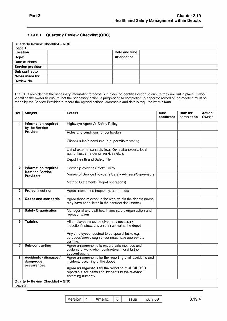
Part 3 Chapter 3.19 Health and Safety Management within Depots
Version 1 Amend. No
8 Issue Date
July 09 3.19.4
3.19.6.1 Quarterly Review Checklist (QRC)
Quarterly Review Checklist – QRC (page 1) Location Date and time Depot Attendance Date of Notes Service provider Sub contractor Notes made by: Review No. The QRC records that the necessary information/process is in place or identifies action to ensure they are put in place. It also identifies the owner to ensure that the necessary action is progressed to completion. A separate record of the meeting must be made by the Service Provider to record the agreed actions, comments and details required by this form.
Ref Subject Details Date
confirmed Date for completion
Action Owner
Highways Agency's Safety Policy;
Rules and conditions for contractors
Client's rules/procedures (e.g. permits to work);
List of external contacts (e.g. Key stakeholders, local authorities, emergency services etc.);
1 Information required by the Service Provider
Depot Health and Safety File
Service provider’s Safety Policy
Names of Service Provider’s Safety Advisers/Supervisors
2 Information required from the Service Provider:-
Method Statements (Depot operations)
3 Project meeting Agree attendance frequency, content etc.
4 Codes and standards Agree those relevant to the work within the depots (some may have been listed in the contract documents)
5 Safety Organisation
Managerial and staff health and safety organisation and representation
All employees must be given any necessary induction/instructions on their arrival at the depot.
6 Training
Any employees required to do special tasks e.g. spreader/snowplough driver must have appropriate training.
7 Sub-contracting Agree arrangements to ensure safe methods and systems of work when contractors intend further subcontracting
Agree arrangements for the reporting of all accidents and incidents occurring at the depot.
8 Accidents / diseases / dangerous occurrences
Agree arrangements for the reporting of all RIDDOR reportable accidents and incidents to the relevant enforcing authority.
Quarterly Review Checklist – QRC (page 2)

Part 3 Chapter 3.19 Health and Safety Management within Depots
Version 1 Amend. No
8 Issue Date
July 09 3.19.5
Ref Subject Details Date confirmed
Date for completion
Action Owner
9 Hazardous conditions Agree arrangements to advise the depot Manager (or their safety supervisor) any hazardous conditions which might expose employees to work in, or have access to such places.
State who provides them and note any exceptions. 10 Welfare facilities/first aid /occupational health and hygiene service
Arrangements for shared facilities to be confirmed by the contractor providing the facilities.
11 Housekeeping Arrangements for storage and removal of industrial and domestic waste.
Agree areas of work where Permit to Work procedures apply.
12 Permits to work (PtW)
Ensure affected contractors are fully aware of current PtW and have the necessary competency, instruction and information.
Ensure Fire Risk Assessment has been completed for all areas of the depot.
Arrangements for raising the alarm, rescue and evacuation procedures in event of fire and other emergency, e.g. release of toxic fumes.
Ensure Fire Log Book is maintained and identified actions are completed.
13 Fire precautions and Emergency Procedures
Agree training, instruction and information to users of the depots.
Ensure depot security arrangements are fit for purpose.
Agree and ensure safe access for vehicles, including disabled vehicles, and pedestrians with clearly marked traffic routes and parking areas.
Agree and ensure mandatory maximum speed limit is set and signed.
Agree arrangements for deliveries, loading and unloading.
14 Access to depot and site security:-
Ensure visitors' booking in and out arrangements are clearly indicated.
15 Authorised users Check contact lists (name and phone number) are current.
16 Other

Part 3 Chapter 3.19 Health and Safety Management within Depots
Version 1 Amend. No
8 Issue Date
July 09 3.19.7
3.19.6.2 Monthly Inspection Report (MIC)
Location Date and TimeDepot AttendanceService ProviderSub-Contractor(s)Completed byReview No:
Activity Defect Location Description No. Items No. Defects Date for Completion
Action Owner Confirmation
Boiler Room(s)
Bottled Gas Storage
Electrical Systems & Lighting
Fencing
Fire Prevention & Emergency Procedures
First Aid
Garage/Workshops
Generators
Inside Stores
Offices
Outside Stores
Recycling & Waste
Salt Storage & Loading
Wash down Area
Welfare Facilities
Other
Procedure for Completion of Form1. MIC details the activity, category and defect descriptions to be used during the health and safety inspection.
2. For items which meet the standard, a tick must be entered in the Confirmation column.3. Items which fail to meet the standard must be recorded using the respective columns.
Monthly Inspection Checklist - MIC

Part 3 Chapter 3.20 Identification of Workplace Hazards within Depots
Version 1 Amend. No
8 Issue Date
July 09 3.20.1
3.20 Identification of Workplace Hazards within Depots 3.20.1 General This chapter describes health and safety legislation regarding workplace hazards typically encountered in Highways Agency depots and must be considered in conjunction with the use of the forms in 3.20.1 and MIC. The Service Provider must comply with all relevant statutory provisions applicable to their work in depots. This may be deemed to cover the general duties under the Health and Safety at Work, etc. Act (HSWA) and the more specific duties in the various Regulations made under the HSWA. The Management of Health and Safety at Work Regulations (MHSWR) places a duty on employers to identify hazards, make appropriate risk assessments and manage the risks accordingly. In particular the Service Provider must prepare a comprehensive risk assessment for each depot detailing likely hazards that may be encountered and the control measures required to mitigate the associated risks. These control measures must be disseminated to all relevant staff working in the depot through regularly held recorded toolbox talks or similar. In addition to this, visitors to the depot must also be made aware of potential risks to their health, safety and welfare, and mitigation methods as part of the depot’s Health and Safety induction. This chapter does not in itself constitute a formal risk assessment by any employer of the health and safety of their employees or others in depots. It is intended to encourage a broadly uniform approach on the part of Service Providers to the identification of hazards, the carrying out of risk assessments and the determination of control measures which must be put into operation to comply with duties under current health and safety legislation. A statutory duty exists on Service Providers as employers to appoint a competent person or persons to assist them in carrying out the requirements imposed on them by the MHSWR and those of specific regulations e.g. the Control of Substances Hazardous to Health Regulations (COSHH), the Manual Handling Operations Regulations, and the Noise at Work Regulations. This is not an exhaustive list and it is the Service Provider’s responsibility to ensure that the requirements of all the latest regulations applying to operations within a depot are complied with. Regulation 9 of the MHSWR identifies particular duties on employers who share a workplace, whether on a temporary or permanent basis, requiring them to co-operate and co-ordinate in the carrying out of their statutory obligations, including the exchange of information and the assessment of shared risks. Depots, by their very nature, can be categorised as shared workplaces. This chapter is intended to ensure that the Highways Agency and Service Provider complies with this statutory obligation through the identification of typical hazards. Upon identification of a hazard the Service Provider must put in place methods of elimination, substitution, reduction or other suitable control measures, inclusive of any precautions or controls already in place to ensure that all risks are as low as reasonably practicable. It is the responsibility of the Service Provider to take all reasonable steps to ensure that employees in depots managed by them co-operate, inform and exchange relevant information concerning the risks arising out of, or in connection with, their undertakings. This may entail, amongst other things, an exchange of health and safety policies, risk assessments, method statements and permit to work systems where appropriate.

Part 3 Chapter 3.20 Identification of Workplace Hazards within Depots
Version 1 Amend. No
8 Issue Date
July 09 3.20.2
3.20.2 Depots as Places of Work 3.20.2.1 General The Workplace (Health, Safety and Welfare) Regulations set general requirements in the four broad areas of working environment, safety, facilities and housekeeping and are supported by an Approved Code of Practice. The Service Provider must ensure that all depots comply with the Workplace Regulations. Smoking in any depot is only allowed in areas designated, and clearly marked, by the Service Provider. Hazards and associated risks identified within the four broad areas of the Workplace Regulations which may be typically found in depots include:-
• slips, trips and falls caused by the accumulation of waste material, debris and obstructions or slippery floors in garages, workshops and pedestrian routes;
• inadequate levels of lighting around machines in the depot yard, near stockpiles, and elsewhere;
• inhalation of toxic gases, fumes and particulates due to inadequate ventilation in garages and workshops;
• hazardous substances; • falls into unguarded, open inspection pits: • plant and vehicular movements.
The Service Provider, subcontractors and Highways Agency staff must identify all relevant hazards associated with their undertakings in the workplace. They must carry out an appropriate risk assessment to determine the measures to be taken to manage the risks to be as low as reasonably practicable. The ensuing control measures must incorporate the general requirements for the specific workplace areas and activities described in 3.20.9.2 to 3.20.9.10. The Service Provider must also ensure the co-operation and exchange of risk assessments or similar relevant information prepared by others concerning their undertakings in the workplace as appropriate. 3.20.2.2 Inspection Pits Before entering an inspection pit a specific risk assessment must be carried out. This must include consideration of the following:- • check whether it is a confined space; • hazardous fumes; • means of access and egress; • fuels and oils; • if considered a confined space then a permit to enter system must be employed; • if hand lamps are used they must be intrinsically safe; • inspection pits must be regularly cleaned and any spillages immediately treated or cleaned up; • unguarded areas must be covered or protected by suitable barriers particularly when the pit is
not in use.

Part 3 Chapter 3.20 Identification of Workplace Hazards within Depots
Version 1 Amend. No
8 Issue Date
July 09 3.20.3
3.20.2.3 Movement of Vehicles Risks with movement of vehicles within a depot include collision with other vehicles, pedestrians, buildings, plant and equipment and hazardous substances storage areas. The maximum speed limit for all depots is 10mph. All vehicles must be safely driven within the speed limit using designated routes and directions. Vehicle and pedestrian movements must be segregated with areas clearly marked. All vehicles, except private vehicles and those restricted to public and staff parking areas, must be reversed using reversing alarms and vehicular fitted reversing lamps with the assistance of trained competent banksmen. All vehicles and equipment must be safely parked or stored in designated areas and vehicular movement lanes must be kept clear of obstruction. Protection by suitable barriers is required during prolonged and/or multi-directional reversing work (e.g. salt loading). 3.20.2.4 Vehicle Exhaust Fumes The release of vehicle exhaust fumes within a workshop or other building may lead to respiratory problems. Engines must not be run inside workshops and garages unless these areas are adequately ventilated to minimise the build up of toxic exhaust fumes. 3.20.2.5 Lighting All workplaces must have suitable and sufficient lighting including emergency lighting as appropriate. Lighting to traffic movement lanes, depot yards, salt barns, loading areas and hoppers must be used when natural light is insufficient for safe working. 3.20.2.6 Fire Precautions The Service Provider must consider work activities in depots managed by them and identify potential hazards that may result in an outbreak of fire. Fire protection and prevention measures must cover all parts of the depot and comply with the requirements of the Fire Precautions Act and other fire regulations to the satisfaction of the local fire authority. Fire is a chemical reaction between a combustible substance (fuel) and oxygen initiated by a source of ignition. It presents a threat through heat, fumes, smoke, explosion, burning and structural collapse. Fire prevention measures centre upon the removal where possible, or control of available fuel and ignition sources. Sources of fuels in depots include petroleum, diesel, oil, liquefied petroleum gas (LPG), industrial gases, paints, solvents and materials such as paper, timber and rags. Possible ignition sources include sparks emanating from machinery, hand tools and electrical equipment, direct flame from cutting and welding operations, hot surfaces, cigarettes and matches.

Part 3 Chapter 3.20 Identification of Workplace Hazards within Depots
Version 1 Amend. No
8 Issue Date
July 09 3.20.4
In order to reduce the risk of fire, the Service Provider must consider all fire hazards and associated risks in each of the depots managed by them. Included in the ensuing control measures, smoking and naked flames must be prohibited in or near the following:- • inspection pits and fitters' workshops; • battery charging rooms or areas where batteries are being charged; • fuel installations and oil storage areas; • storage areas for paint, thinners, chemicals, weed killers, etc; • LPG containers; • accumulations of combustible materials and other areas where no smoking, no naked lights or
highly flammable signs are displayed; • and any other area where smoking or a naked flame may constitute a danger. The Service Provider must ensure that combustible waste and debris are controlled by efficient housekeeping and safe disposal. Only minimum supplies of flammable materials must be kept in depots. The use and storage of petroleum, LPG and other highly flammable and/or explosive substances must comply with the requirements of the Petroleum Consolidation Acts and the Highly Flammable Liquids and Liquefied Petroleum Gases Regulations. 3.20.3 Work Equipment 3.20.3.1 General The Service Provider must reduce the risks to the health, safety and welfare of their employees and others who may be affected by their operations involving work equipment in depots. They must comply with the general duties and specific requirements of the Provision and Use of Work Equipment Regulations (PUWER). Work equipment is defined as any machine, apparatus, tool or installation used at work. Use is defined as starting, stopping, repairing, modifying, installing, dismantling, programming, setting, transporting, maintaining, servicing and cleaning. The need for appropriate training, maintenance and suitability assessments applies to all equipment. The Service Provider must further ensure compliance with Regulations for specific work equipment and its use, for example, Lifting Operations and Lifting Equipment Regulations (LOLER). Equipment must be used in accordance with the manufacturer’s recommendations. Appropriate information and training must be provided to all operators of such work equipment. The Service Provider must comply with their duties under the Workplace Regulations regarding the identification of all hazards associated with work equipment used in depots. The risk assessments must identify control measures to ensure safe systems of work including operating instructions and training. The control measures must include instructions for the specific work equipment identified in 3.20.3.2 to 3.20.9.10. The Service Provider must ensure the co operation and exchange of risk assessments or similar relevant information prepared by other employers concerning their undertakings involving the use of work equipment in depots. Regulations state that all plant, machinery and equipment must be fit for purpose, properly maintained and safe. When a defect is identified in the operation, suitability or maintenance of such equipment it must be put out of use immediately. All defective equipment must be marked as defective, or placed in a quarantine area, where there is restricted access.

Part 3 Chapter 3.20 Identification of Workplace Hazards within Depots
Version 1 Amend. No
8 Issue Date
July 09 3.20.5
Guarding of machinery is provided to protect the user from inherent hazards of the work equipment, such as moving parts, yet one of the most common hazards associated with the use of work equipment is the lack of suitable guarding or its deliberate removal. Other hazards associated with work equipment include traps, impact, contact, entanglement, ejection, electricity, chemicals, temperature, vibration, and noise. Guarding on work equipment must not be removed or modified by the user. Where guards are missing the work equipment must be put out of use immediately and reported. 3.20.3.2 Lifting Equipment Hazards include the use of worn or poorly maintained equipment and unsuitable equipment for the task. All lifting equipment must be adequate and appropriate for the task. Safe permissible working loads must be marked on all lifting equipment and rigorously adhered to. Before any piece of lifting equipment is used the requirements contained in LOLER appropriate to the equipment must be met. 3.20.3.3 Use of Jacks Only jacks of adequate lifting capacity appropriate to the item to be lifted will be used. Jacks must only be used to raise vehicles to enable adequate supports to be fixed. Work must only take place under the vehicle when such supports are correctly positioned. 3.20.3.4 Hydraulic Equipment With any hydraulically raised equipment, work must not commence until the safety bars, frames or pins have been fitted. 3.20.3.5 Steam Cleaning and Pressure Washers Problems may occur in these operations due to prolonged operator exposure to the sprays, chemical fumes and high pressures which can cause personal injury. The operator must wear appropriate personal protective equipment as determined by the risk assessment for the activity being carried out. 3.20.3.6 Abrasive Wheels The following precautions apply to the use of abrasive wheels:- • abrasive wheels must only be used when effective machine guards to rotating parts are in
place; • the floors and areas surrounding fixed machines must be kept in good condition and free from
obstruction; • splash guards must be used where appropriate to prevent the surrounding areas becoming
slippery; • only trained operators must fit abrasive wheels and operate such machinery;

Part 3 Chapter 3.20 Identification of Workplace Hazards within Depots
Version 1 Amend. No
8 Issue Date
July 09 3.20.6
• appropriate personal protective equipment as determined by the risk assessment for the activity must be worn.
3.20.3.7 Pressure Greasing Equipment The following precautions apply to the use of pressure greasing equipment:- • fittings must be secure; • hoses must be in good order; • filters must be functioning correctly; • safety valves must be operating correctly; • appropriate personal protective equipment as determined by the risk assessment for the activity
must be worn. 3.20.3.8 Drills Appropriate personal protective equipment as determined by the risk assessment for the activity must be worn. Effective guarding of the rotating parts and secure clamping of the work piece must be provided in accordance with the risk assessment. 3.20.3.9 Hand Tools Hand tools are often overlooked in the maintenance regime for work equipment yet the same regulations apply. The correct tools for the job must be used, including consideration of the use of low vibratory tools. Tools must be maintained in good condition and stored properly. Any defective tools must not be used. All tools must be regularly cleaned with moving and adjustable parts lightly oiled to prevent wear and misalignment. Cutting edges must be kept sharp and sharpened in the correct manner to prevent a change in the temper of the metal. Metal tools conduct electricity and therefore where work is taking place on or near electrical apparatus, insulated tools must be used. Sparks from tools can cause fire or explosion and care must be taken near combustible or flammable materials. The user must wear appropriate personal protective equipment as determined by the risk assessment for the activity being carried out. 3.20.3.10 Welding and Cutting Operations Hazards common to gas and electric arc welding and cutting operations include fire, explosion, burns, noise, the production of toxic fumes and metal splatter. Hazards associated with gas welding are the use of inflammable gases and the effects of possible oxygen enrichment, particularly in confined or inadequately ventilated areas. Electric arc welding hazards can result from poor standards of maintenance, repair and improper use of equipment. There is also a risk to the eyes and skin from the effects of ultraviolet light from the arc. These hazards must be identified on the depot risk assessment and the risks advised to the staff in the depot through regularly held recorded toolbox talks.

Part 3 Chapter 3.20 Identification of Workplace Hazards within Depots
Version 1 Amend. No
8 Issue Date
July 09 3.20.7
The Service Provider must take all reasonable steps to ensure that every aspect of work involving welding and cutting operations in depots is considered to identify hazards and assess risks. Consideration must be given to the use of hot work permits, in appropriate situations, including work in confined areas and other locations away from workshops. A specific risk assessment must be completed to determine appropriate control measures including segregation from the work, use of barriers, non-reflecting welding screens, working signs and the suitability of personal protective equipment. Following risk assessments, identified control measures must include the following requirements (not deemed to be exhaustive or necessarily covering all eventualities and hazards) to personnel in depots: • the undertaking of work involving welding and cutting is restricted to persons trained and • competent in the use of and familiar with the safety procedures appropriate to the equipment; • personal protective equipment provided to prevent accident or injury to the body, eyes and
head must be worn during any welding and cutting operations; • protective coatings (paint) must be removed from around areas to be welded to avoid the • possibility of the emission of toxic gases; • welding and cutting work on vehicle fuel tanks or any other vessel designed to contain • flammable or explosive substances are prohibited in depots. The Service Provider must ensure the co-operation and the exchange of risk assessments, including the mitigation processes, or similar relevant information prepared by employers for all operatives engaged in welding and cutting operations in depots. 3.20.4 Hazardous Substances The classification of hazardous substances is laid down in the Chemicals (Hazard Information and Packaging) Regulations. The physical form assumed by a hazardous substance or preparation (liquid, gas, dust, fumes or vapour, etc.) is a contributing factor to its potential for harm. Substances included in the Regulations are found in depots including:
• liquid - solvents, petroleum, paints, acid (battery charging), coal tar pitch derivations; • gas - carbon monoxide (vehicle exhaust), hydrogen (battery charging), Liquid Petroleum
Gas (LPG), oxides of nitrogen (welding); • dust - metal dust (grinding machine), cement, salt; • fumes - metal fume (welding); • vapour - solvents.
Working practices must aim to minimise the risks associated with using hazardous substances and the consequences of any accidents. The use, storage, handling and generation of certain hazardous substances must satisfy the requirements of the Control of Substances Hazardous to Health Regulations (COSHH). In addition there are specific regulations providing requirements for the use and storage of a number of hazardous substances (e.g. the Control of Lead at Work Regulations, the Control of Asbestos at Work Regulations, the Highly Flammable Liquids and Liquefied Petroleum Gases Regulations, Dangerous Substances and Explosive Atmospheres Regulations). The Service Provider and all other employers in depots are under a legal duty to provide safe systems of work for their staff and others who may be affected by their undertakings. The COSHH regulations require an assessment to be conducted prior to any work involving a hazardous substance. Risk (COSHH) assessments must include the need to ensure that all

Part 3 Chapter 3.20 Identification of Workplace Hazards within Depots
Version 1 Amend. No
8 Issue Date
July 09 3.20.8
hazardous substances are used in accordance with the manufacturer’s recommendations and that suitable control measures are implemented. Employers must ensure that sufficient information and training, is provided to users of such hazardous substances and those who are affected by their use. The Service Provider must ensure the co operation and exchange of relevant instructions including risk assessments prepared by all employers concerning their undertakings involving hazardous substances. 3.20.5 Flammable, Toxic and Corrosive Substances 3.20.5.1 General Before working with substances personnel must have received relevant training and fully understand manufacturers' instructions regarding correct and safe procedures for the storage, use and disposal of flammable, toxic and corrosive substances. A detailed risk assessment, that is recorded, must be carried out prior to any work involved with the use or movement of Flammable, Toxic and Corrosive Substances. The following precautions act as a guide and must be taken as best practice where possible, but are by no means exhaustive and are dependent on the specific nature of the substances involved:- • only the minimum quantities of such substances must be in use, or stored; • storage must be in an approved area or container; • liquids must always be moved in suitable, securely capped cans or drums on which the
contents are clearly marked; • pouring of liquids must be carried out with funnels and there must be no naked flame within 6
metres of the operations or other set distance as instructed by the manufacturer; • screw tops and stoppers must be replaced immediately; • drums in use that are fitted with taps must be provided with drip trays; • drums in use must be stored on end or in cradles; • drums not in use must be stored on end; • empty containers must be stored in an approved area; • consideration must be given to the use of intrinsically safe electrical fittings. 3.20.5.2 Liquefied Petroleum Gas (LPG) LPG storage and use must comply with the requirements of the Dangerous Substances and Explosive Atmospheres Regulations. 3.20.5.3 Packaging and Labelling of Dangerous Substances The packaging and labelling of dangerous substances supplied for use and storage in depots must comply with the requirements of the Chemicals (Hazard Information and Packaging for Supply) Regulations (CHIPS). Substances received for delivery must only be accepted with the correct packaging and labelling. 3.20.6 Manual Handling Operations Injuries are common with manual handling. They can be caused by using incorrect lifting techniques, not taking full consideration of the load to be lifted, or excessive carrying or handling of the load.

Part 3 Chapter 3.20 Identification of Workplace Hazards within Depots
Version 1 Amend. No
8 Issue Date
July 09 3.20.9
Operations involving the manual handling of loads by employees at work which may result in injury must be identified by a general risk assessment as required by the MHSWR. The Manual Handling Operations Regulations in turn require that manual handling must be avoided or reduced as far as is reasonably practicable. Where it is not reasonably practicable to avoid manual handling operations that may result in injury, the Service Provider and other employers must conduct a specific risk assessment to determine how to manage the risks accordingly. All employees required to undertake manual handling of such loads must be adequately trained and must make use of any other controls, instructions and procedures determined from risk assessments. 3.20.7 Electricity at Work 3.20.7.1 General The principal risks associated with the use of electricity at work include electric shock, electrical explosions, burns and electrical fires. Electric shocks may result from direct or indirect contact with live conductors and may increase the risk of falls from height (e.g. falls from ladders and scaffolding caused initially by shock currents or explosions). Other risks that may result from the unsafe use of electrical apparatus include slips, trips and falls due to trailing cables. The Electricity at Work Regulations control the use of electricity in the workplace, by imposing duties on employers and employees. The regulations are supported by Health and Safety Executive’s guidance document Memorandum of Guidance on the Electricity at Work Regulations. The Service Provider must ensure that any duties imposed by them on their employees which involves work on or near to electrical conductors complies with the regulations. All such work must also meet the design, testing and installation requirements of the latest edition of the Institution of Electrical Engineers Regulations for Installations. 3.20.7.2 Low Voltage Installations These instructions apply to all work carried out on low voltage installations. Where a distribution system is supplied from the supply authority's low voltage mains, these rules must be applicable to all switchgear and apparatus installed after the supply authority's equipment. Prior to any low voltage installation work the risk assessment must be completed to identify adequate training, the prevention and protection methods to be used (including the need for a Permit to Work system) and the emergency procedures to be adopted. 3.20.7.3 Working on 'Live' Equipment Only appropriately qualified persons will inspect or work on or near equipment or cables that are electrically live. Prior to any work on live equipment the risk assessment must be completed to identify adequate training, the prevention and protection methods to be used (including the need for a Permit to Work system) and the emergency procedures to be adopted.

Part 3 Chapter 3.20 Identification of Workplace Hazards within Depots
Version 1 Amend. No
8 Issue Date
July 09 3.20.10
3.20.7.4 Distribution Switchrooms/Server Rooms Switchrooms must be kept free of all obstructions (e.g. surplus materials or spares) to minimise the possibility of persons falling while carrying out work on or inspecting live equipment. Unattended distribution switchrooms must be kept locked and access must be restricted to competent persons. 3.20.7.5 Circuit Identification All circuits identified on switches and distribution boards must be clearly and correctly shown. When circuit re-arrangements or additions are carried out, the identities on switches and distribution boards must be updated. New labels must be prepared in advance and must be fixed in position immediately the circuit re-arrangements or additions are completed. Handwritten or other temporary labels must only be used in exceptional circumstances and then only for a limited period until typed labels are prepared and attached. When such re-arrangements or additions are made all records must be immediately updated. 3.20.8 Winter Maintenance Equipment and Other Vehicles
3.20.8.1 General There are hazards associated with work involving winter maintenance equipment and other vehicles, all of which may result in personal injury accidents. Injuries can occur due to hazards associated with:
• direct bodily contact with machines, • entanglement in machinery • ejection of salt particles from moving parts of winter maintenance vehicles and equipment, • slips, trips and falls on slippery or obstructed surfaces.
The Service Provider must take all reasonable steps to ensure that hazards associated with work involving winter maintenance equipment and other vehicles are considered by each employer whose undertakings include such operations. Resulting risk assessments must determine the control measures to be taken in order to comply with relevant statutory provisions. The ensuing control measures must incorporate the requirements for the specific work activities in 3.20.8.2. These requirements are not exhaustive or necessarily cover all work activities involving winter maintenance equipment and other vehicles. Only appropriately trained and qualified personnel must operate winter maintenance vehicles or equipment. The Service Provider must ensure the co-operation and exchange of risk assessments or similar relevant information prepared by employers engaged in such work. 3.20.8.2 Snow Plough Blades Snow plough blades must be kept in designated areas within garages and on the carrier frame provided to allow safe movement and attachment to the vehicle. The area around snow plough blades must be kept clear at all times to allow unhindered and safe access to the blades. Movement and attachment of snow plough blades must only be carried out by appropriately qualified personnel.

Part 3 Chapter 3.20 Identification of Workplace Hazards within Depots
Version 1 Amend. No
8 Issue Date
July 09 3.20.11
3.20.9 Salt Loading Equipment, Storage and Handling 3.20.9.1 General Hazards associated with salt in depots include potential instability of salt stockpiles, the hazardous effects of operatives’ prolonged exposure to salt, the effects of adverse weather conditions and dangers accompanying the movement and ascent/descent of hoppers by persons at work. The Service Provider must take reasonable steps to ensure that every aspect of work associated with salt storage, handling and loading is considered by the employees and employer involved in such work. Appropriate risk assessments must determine the measures to be taken to comply with relevant statutory provisions and the ensuing control measures must incorporate the instructions for the specific items and operations identified in 3.20.9.2 and 3.20.9.3. These requirements are not exhaustive or necessarily cover all work activities involving salt storage, handling and loading. The Service Provider must ensure the cooperation and exchange of relevant information including risk assessments prepared by all employers concerning their undertakings involving salt in depots. 3.20.9.2 Salt Loading Equipment (Hoppers) Operative must keep clear of moving parts and ensure that all guards, screens and ladder loops are in place and remain closed or locked, as appropriate, during operations. Operatives must keep clear of the underside of hoppers when salt is being loaded or dispersed to avoid injury from falling salt. The soundness and security of all guards must be checked. Maintenance operations in hopper bins must only be carried out by competent maintenance contractors using a permit to work system. Ascents and descents of the hopper during normal operations must be by the ladders or steps provided and movement on the hopper restricted to the staging catwalks within handrails. Loose items must not be left on the hopper and lightweight items of large area e.g. inspection hatches, must be properly secured. All personnel movements and activities during exceptionally strong winds and other adverse weather conditions must be assessed and restricted particularly before they ascend hoppers. 3.20.9.3 Salt Storage and Handling Work in the vicinity of the salt storage area must only be undertaken by persons who are trained in and aware of the hazards and associated risks involved with the handling of salt and its associated stockpiles (particularly where salt is stored in the open). Salt must, wherever possible, be stored in salt barns. When stored in the open salt piles must be formed into the shape of long rectangles (dimensions to suit the yard being utilised) because large conical piles of salt present unacceptable hazards. The top surface of the salt pile must be convex to ensure that when sheeted there are no valleys formed as seepage of rain through cracks or joins in the sheeting may form crevices in the salt leading to potential collapse of the salt pile. When storing salt in barns, salt must not be placed above the fill line on the retaining wall and at that level a minimum one metre wide strip perpendicular to the wall must be left to avoid overstocking, pollution and spillage.

Part 3 Chapter 3.20 Identification of Workplace Hazards within Depots
Version 1 Amend. No
8 Issue Date
July 09 3.20.12
As salt is removed from the stockpile a positive slope, not exceeding 60 degrees to the horizontal, must be maintained to avoid risk to staff and vehicles from the collapse of cliff walls of salt. High winds create further risks to existing control measures in the safe storage of salt. Sheeting, weights and anchorages must be properly secured at all times to mitigate these risks. Service provider staff must draw any such hazards to the attention of supervisory staff. 3.20.9 Personal Protective Equipment (PPE) 3.20.9.4 General The Service Provider must comply with their duties under the MHSWR and other relevant legislation regarding the identification of all hazards associated with their work activities in depots. Resulting risk assessments must determine control measures necessary to ensure safe systems of work. A hierarchy of control measures exists involving the elimination, substitution, reduction, isolation or other means of control of the risks. If these procedures fail to offer an adequate degree of control, i.e. are insufficient to reduce risks to as low a level as is reasonably practicable, then as a last resort, personal protective equipment (PPE) must be provided to control the residual risks. Additionally some legislation requires personal protective equipment to be worn irrespective of other control measures in place. The Service Provider is therefore required to comply with the requirements imposed on them by the Personal Protective Equipment at Work (PPE) Regulations and a systematic approach must be followed ensuring that workers at risk are properly protected. The main elements of this approach must include the selection, introduction and use, maintenance and storage, and a system designed to monitor its effectiveness. Further, where necessary, appropriate information, instruction and training in the use of PPE must be provided before use. The selection of personal protective equipment (its type and form) must consider, amongst other things, the scale and type of hazard, fumes, dust, noise etc., specific job restrictions, such as work in confined areas, the needs of the user in terms of comfort, ease of movement and use, the cleaning, maintenance and replacement and other specific regulations currently in place, e.g. the Construction (Head Protection) Regulations. The Service Provider must ensure that all aspects of work in depots requiring the provision of PPE are assessed and that PPE provided is in accordance with the relevant BS EN standard, e.g. BS EN 471 (Retro reflective clothing). It is normal practice for Service Providers to issue standard personal protective equipment to their own operatives and staff for normal operations and activities undertaken by them. However, it is necessary for the Service Provider to ensure that where activities and operations are taking place that necessitate non-standard or additional personal protective equipment, this is available and provided to all staff and operatives, even if they are not their own employees. It is necessary to ensure that the provision of personal protective equipment is not compromised by the use of other personal protective equipment or the person’s own characteristics, e.g. the need for glasses, beards, etc. 3.20.9.5 Safety Helmets Wherever there exists a risk of head injury, safety helmets must be worn in accordance with the requirements of the Construction (Head Protection) Regulations. Typical situations include areas

Part 3 Chapter 3.20 Identification of Workplace Hazards within Depots
Version 1 Amend. No
8 Issue Date
July 09 3.20.13
where structural maintenance or new construction is being carried out and where activities involve work below winter maintenance vehicles and salt loading hoppers and these must be clearly defined and signed and their locations clearly identified to all operatives and personnel using the depot. 3.20.9.6 High Visibility Garments Class 3 retroreflective fluorescent jackets with full length sleeves must be worn in all areas within the depot. Exceptions will only apply in areas designated by the depot manager. 3.20.9.7 Hearing Protection Typical work activities in depots where noise levels may present a risk include the use of machinery, plant, welding and cutting operations, particularly in confined spaces Hearing protection must be provided and worn as required by the Noise at Work Regulations. In all work activities where noise levels present a risk of occupational hearing loss, the principle must always be to reduce the noise at source to at least an acceptable level and preferably to the lowest level possible below the current action levels required by the Noise at Work Regulations. The wearing of hearing protection must always be regarded as a last resort control measure. Ear defenders must always be worn in the cabs of snow blowers. 3.20.9.8 Welding and Cutting Operations Operators and others affected by welding and cutting operations must wear the PPE determined by the risk assessment. Typically, this will include face shields, welding helmets, gauntlets and aprons to protect against burns, metal splatter and the effects of ultraviolet radiation and the use of hearing protection particularly in confined spaces. 3.20.10.6 Work on Hoppers The risk assessment for work on hoppers may identify the requirement for the use of PPE. This is likely to include a safety helmet with a chin strap, hearing and eye protection, gloves and protective clothing and in particular a safety harness to protect against falls from height noise, hazardous substances and falling objects.

Part 3 Annex 3.5.1 The Management of Sub-Standard Highway Structures,
Concrete Half Deck and Hinge Deck Structures – Background Information
Version 1 Amend. No
8 Issue Date
July 09 A3.5.1
Annex 3.5.1 The Management of Sub-Standard Highway Structures, Concrete Half Deck and Hinge Deck Structures – Background Information Background The recent failures of major highway structures in Canada, the USA and elsewhere in the world have been widely publicised and whilst various contributing factors are apparent, common issues are emerging. Amongst these are management of safety critical and vulnerable features of structures, quality of inspections and record keeping, and there are lessons to be learnt that are applicable to UK highway structures, and the Highways Agency assets. The Commission of Enquiry into the collapse of the de la Concorde overpass in Montreal which had concrete deck half joints, reported that, whilst there were a number of contributing factors, “the overpass collapsed as a result of shear failure of the south-east cantilever…” “The collapse was due to the development and growth of a crack in a zone of weakness located under the upper rebars starting from the beam seat area (Half joints). Over the years, the freeze-thaw cycles along with de-icing salts, caused the concrete to deteriorate in this area. This deterioration caused a cracking plane to spread inside the thick slab.” The Commission of Enquiry went on to report: “For the entire period of time for which the Ministère des Transports du Quèbec (MTQ) was responsible for the overpass the structure was never subjected to an inspection and maintenance programme that took account of its particular characteristics, notably, the critical beam seats at the ends of the cantilevers” (Half joints) “The commission is of the opinion that the vulnerabilities of the de la Concorde overpass, a unique structure that was difficult to inspect, were not taken into account adequately by the MTQ. The MTQ did not rigorously and effectively deploy all the means at its disposal to properly evaluate the condition of the overpass despite numerous signs of deterioration. It also failed to maintain adequate records …” “The commission finds that the overpass inspections were at time deficient, lacking adequate quantification of the deterioration, sometimes incomplete because not enough time was devoted to the inspections and not thorough because the inspectors failed to look for the reasons behind the deterioration.” The Commission made a number of recommendations regarding targeted inspections and diagnosis and the implementation of “an accelerated, comprehensive and easily accessible on-line system containing all records and data relevant to the structure, including reports on inspections and repair activities.” Although the Highways Agency already has requirements [including the DMRB standards, CHE memoranda, IAN and systems (e.g. SMIS) supporting the above recommendations it is concerned that they are not always being followed. For this reason, requirements are mandated at 3.5.4.4.