Embed Size (px)
Citation preview
Center for Wireless Communications 1©Deng, Larson and Gudem, May 16th, 2003
PA Workshop
High Efficiency SiGe BiCMOS WCDMA
Power Amplifiers
With Dynamic Biasing Techniquesby
Junxiong Deng1, Prasad Gudem2, Larry Larson1, Peter Asbeck1
1University of California at San Diego2Qualcomm, San Diego, CA

Center for Wireless Communications 2©Deng, Larson and Gudem, May 16th, 2003
Presentation Outline
Research Goals Proposals and Implementation
Standard Bias Techniques Dynamic Current Biasing Dynamic Voltage Biasing
Status and Future Work Conclusion

Center for Wireless Communications 3©Deng, Larson and Gudem, May 16th, 2003
Research Goals
SiGe BiCMOS Power Amplifiers for WCDMA applications with far higher efficiency than existing approaches
Good Average Efficiency Although peak efficiency is more than 50%
for class AB, but average efficiency is only 2%
High Output Power (+27dBm) High Power Gain ( > 21dB) Low Noise Figure (10dB) Small Error Vector Magnitude (EVM<10%) Adjacent Channel Leakage Ratio (ACLR>33dB for 5MHz)

Center for Wireless Communications 4©Deng, Larson and Gudem, May 16th, 2003
Standard Biasing Techniques
10*Rbias Rbias
RFin
x/10 x
x/10
Vcc Vcc
Vcc
RFin
x
Constant current biasing
A
The DC current does NOT change as RF power increases

Center for Wireless Communications 5©Deng, Larson and Gudem, May 16th, 2003
Standard Biasing of PA – Constant Current Biasing
Constant current biasing: Poor Linearity!
• The key here is to realize that the average collector currents needs to remain constant. Therefore the quiescent base-emitter voltage falls as shown in the figure on the left. Note that the drop in quiescent base-emitter voltage results in a degradation of the linearity of the amplifier because the current would clip at lower input power.
CI
BEV
inRF
120 mA
BEQV
0.8V
SP
CQI
120 mA

Center for Wireless Communications 6©Deng, Larson and Gudem, May 16th, 2003
Standard Biasing of PA – Constant Voltage Biasing
RFi n
x
Ll arge
Vbb
Constant Voltage Biasing The advantage is that the DC current increases as
the RF power increases. Due to this increase in DC current the linearity of the RF amplifier improves. At the same time, compared to a power amplifier always burning large bias current, constant voltage bias scheme also saves much power.
Good enough? No!
CI
BEV
inRF
450
mA120 mA
BEQV
0.8V
SP
CQI
120 mA

Center for Wireless Communications 7©Deng, Larson and Gudem, May 16th, 2003
Dynamic Current and Voltage Biasing Principle
Ic
VceVmax
Imax
DVB
DCBDCB+DVB
Ic.bias
Vce.bias
A
Vmin
Dynamic Biasing Strategies: DCB, DVB, and DCB+DVB(DCB means Dynamic Current Biasing; DVB means Dynamic voltage biasing.)
Previous Researches: DCB: Conexant, RFMD DVB: UCSD (Prof. P. Asbeck)
Motorola (J. Staudinger)
Challenges: DCB: gain change DVB: gain change, cost, chip
size (dc-dc converter)

Center for Wireless Communications 8©Deng, Larson and Gudem, May 16th, 2003
Dynamic Current Biasing – Gain and Phase Issue
How does gain and phase change?
PA
Idc
QPSK
G
(a) (b)
Center for Wireless Communications 9©Deng, Larson and Gudem, May 16th, 2003
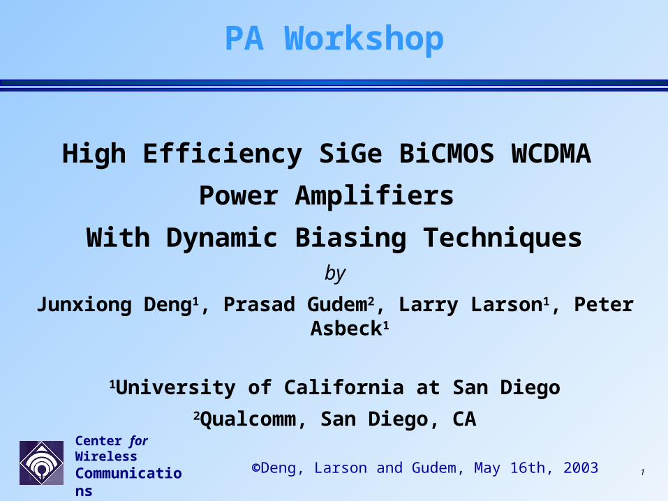
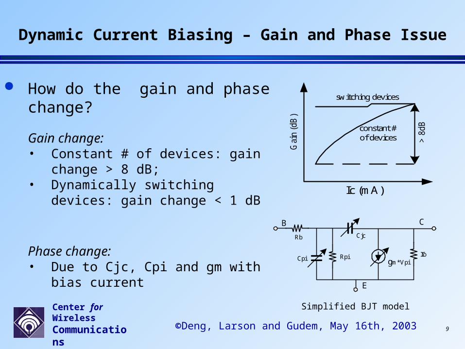
How do the gain and phase change?
Gain change: • Constant # of devices: gain change > 8 dB; • Dynamically switching devices: gain
change < 1 dB
Phase change:• Due to Cjc, Cpi and gm with bias current
Gai
n (
dB
)
Ic (mA)
> 8
dB
switching devices
constant #of devices
B
E
C
Rb
Cpi Rpi
Cjc
gm*Vpiro
Simplified BJT model
Dynamic Current Biasing – Gain and Phase Issue
Center for Wireless Communications 10©Deng, Larson and Gudem, May 16th, 2003
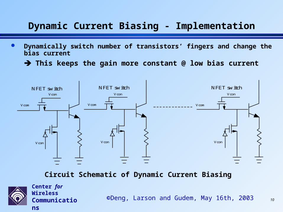
Dynamically switch number of transistors’ fingers and change the bias current
This keeps the gain more constant @ low bias current
Circuit Schematic of Dynamic Current Biasing
Dynamic Current Biasing - Implementation
NFET switchVcon
Vcom
Vcon
NFET switchVcon
Vcom
Vcon
NFET switchVcon
Vcom
Vcon

Center for Wireless Communications 11©Deng, Larson and Gudem, May 16th, 2003
Dynamic Current Biasing – Simulation Results
DC Current and Gain under different bias conditions
constant bias’s average efficiency: 2.4% dynamic bias’s average efficiency: 5.8% (improved by 140% !!!) gain almost constant !!!
Center for Wireless Communications 12©Deng, Larson and Gudem, May 16th, 2003
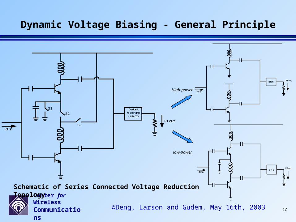
Dynamic Voltage Biasing - General Principle
OutputMatchingNetwork
RFin
RFout
S1
S1
S2
RFin
RFoutOMN
RFin
RFoutOMN
High-power
low-power
Schematic of Series Connected Voltage Reduction Topology

Center for Wireless Communications 13©Deng, Larson and Gudem, May 16th, 2003
Dynamic Voltage Biasing - Implementation
RFin
RFoutOMN
100xdevices
`Vcc
Vcc
Vcc/2
20xdevices
IMN
Group A
Group B
NFET switch
Vcon
Vcon
Vcon
Vcon
CVB
CVB
CCB
- Schematic of Output Stage with
hi-power and low-power groups

Center for Wireless Communications 14©Deng, Larson and Gudem, May 16th, 2003
Dynamic Voltage Biasing – Simulation Results
(Courtesy P. Asbeck)
( )
( )
( )
out out out
out out out
out
P p P dP
P p P dP
P
Pe (%) and Idc (mA) vs. Pout (dBm)
0
0.5
1
1.5
2
2.5
3
3.5
4
4.5
5
-24 -20 -16 -12 -8 -4 0 4 8 12 16 20 24
Pout (dBm)
Pe
(%
)
0
100
200
300
400
500
600
Idc
(mA
)
Pe
ClassAB
Ideal DCB 1stepDVB1stepDCB
Center for Wireless Communications 15©Deng, Larson and Gudem, May 16th, 2003
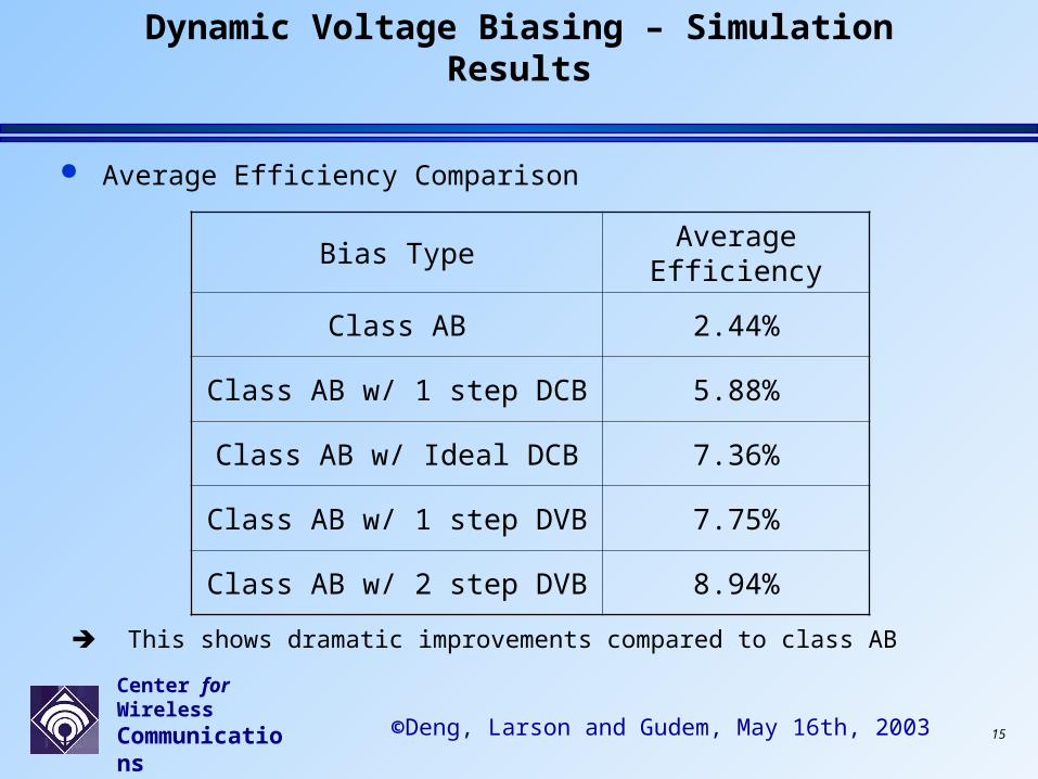
Dynamic Voltage Biasing – Simulation Results
Average Efficiency Comparison
Bias Type Average Efficiency
Class AB 2.44%
Class AB w/ 1 step DCB 5.88%
Class AB w/ Ideal DCB 7.36%
Class AB w/ 1 step DVB 7.75%
Class AB w/ 2 step DVB 8.94%
This shows dramatic improvements compared to class AB
Center for Wireless Communications 16©Deng, Larson and Gudem, May 16th, 2003
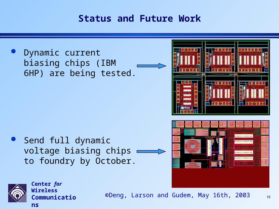
Status and Future Work
Dynamic current biasing chips (IBM 6HP) are being tested.
Send full dynamic voltage biasing chips to foundry by October.
Center for Wireless Communications 17©Deng, Larson and Gudem, May 16th, 2003
Conclusions
In summary, research has been carried out to improve average power efficiency of WCDMA PA, by doing dynamic current and voltage biasing.
The key point of our research is to keep power gain to be constant while improving average power efficiency. Simulation results have indicated the validity and effectiveness of the proposed method. Measurement results will come out soon.
With our dynamic biasing techniques, average power efficiency can be improved by more than 200%!!!