Embed Size (px)
Citation preview
Sony Corporation
Cell Sorter SH800 Quick Reference Guide
March 2013
Ver. 1.4
● Introduction
Page 2
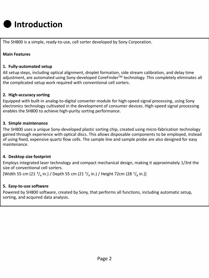
The SH800 is a simple, ready-to-use, cell sorter developed by Sony Corporation.
Main Features
1. Fully-automated setup
All setup steps, including optical alignment, droplet formation, side stream calibration, and delay time adjustment, are automated using Sony-developed CoreFinderTM technology. This completely eliminates all the complicated setup work required with conventional cell sorters.
2. High-accuracy sorting
Equipped with built-in analog-to-digital converter module for high-speed signal processing, using Sony electronics technology cultivated in the development of consumer devices. High-speed signal processing enables the SH800 to achieve high-purity sorting performance.
3. Simple maintenance
The SH800 uses a unique Sony-developed plastic sorting chip, created using micro-fabrication technology gained through experience with optical discs. This allows disposable components to be employed, instead of using fixed, expensive quartz flow cells. The sample line and sample probe are also designed for easy maintenance.
4. Desktop size footprint
Employs integrated laser technology and compact mechanical design, making it approximately 1/3rd the size of conventional cell sorters.
[Width 55 cm (21 3/4 in.) / Depth 55 cm (21 3/4 in.) / Height 72cm (28 3/8 in.)]
5. Easy-to-use software
Powered by SH800 software, created by Sony, that performs all functions, including automatic setup, sorting, and acquired data analysis.
● System Configuration and Name of Parts
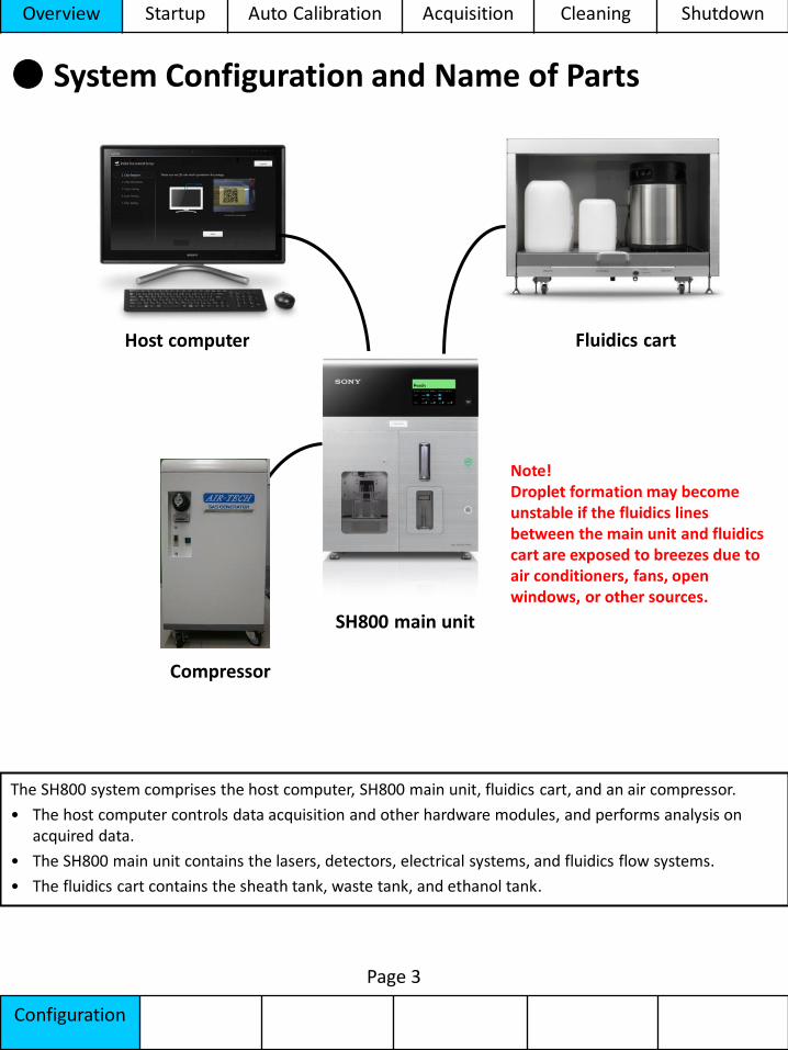
The SH800 system comprises the host computer, SH800 main unit, fluidics cart, and an air compressor.
• The host computer controls data acquisition and other hardware modules, and performs analysis on acquired data.
• The SH800 main unit contains the lasers, detectors, electrical systems, and fluidics flow systems.
• The fluidics cart contains the sheath tank, waste tank, and ethanol tank.
Overview Startup Auto Calibration Acquisition Cleaning Shutdown
Configuration
Host computer
SH800 main unit
Fluidics cart
Page 3
Compressor
Note! Droplet formation may become unstable if the fluidics lines between the main unit and fluidics cart are exposed to breezes due to air conditioners, fans, open windows, or other sources.
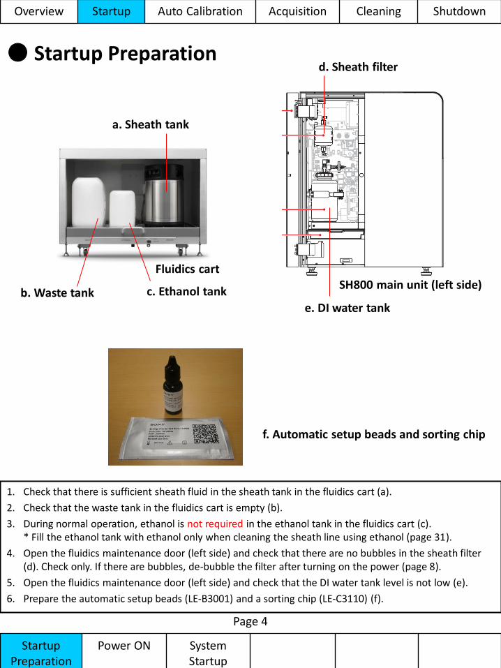
● Startup Preparation
1. Check that there is sufficient sheath fluid in the sheath tank in the fluidics cart (a).
2. Check that the waste tank in the fluidics cart is empty (b).
3. During normal operation, ethanol is not required in the ethanol tank in the fluidics cart (c). * Fill the ethanol tank with ethanol only when cleaning the sheath line using ethanol (page 31).
4. Open the fluidics maintenance door (left side) and check that there are no bubbles in the sheath filter (d). Check only. If there are bubbles, de-bubble the filter after turning on the power (page 8).
5. Open the fluidics maintenance door (left side) and check that the DI water tank level is not low (e).
6. Prepare the automatic setup beads (LE-B3001) and a sorting chip (LE-C3110) (f).
Startup Preparation
Power ON System Startup
Page 4
a. Sheath tank
c. Ethanol tank
Fluidics cart
d. Sheath filter
e. DI water tank
SH800 main unit (left side) b. Waste tank
f. Automatic setup beads and sorting chip
Overview Startup Auto Calibration Acquisition Cleaning Shutdown
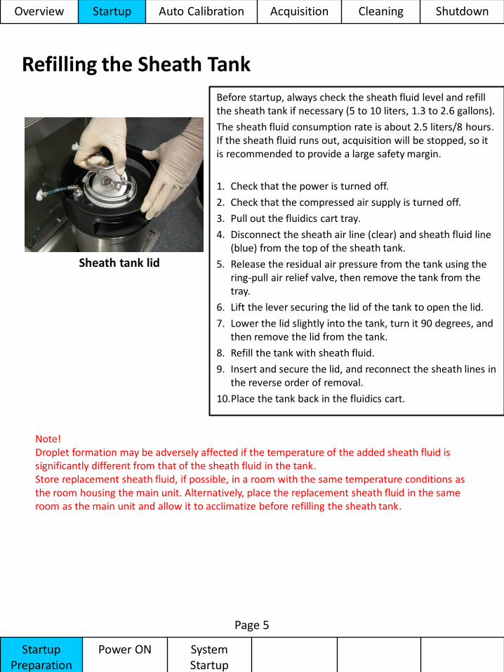
Refilling the Sheath Tank
Before startup, always check the sheath fluid level and refill the sheath tank if necessary (5 to 10 liters, 1.3 to 2.6 gallons).
The sheath fluid consumption rate is about 2.5 liters/8 hours. If the sheath fluid runs out, acquisition will be stopped, so it is recommended to provide a large safety margin.
1. Check that the power is turned off.
2. Check that the compressed air supply is turned off.
3. Pull out the fluidics cart tray.
4. Disconnect the sheath air line (clear) and sheath fluid line (blue) from the top of the sheath tank.
5. Release the residual air pressure from the tank using the ring-pull air relief valve, then remove the tank from the tray.
6. Lift the lever securing the lid of the tank to open the lid.
7. Lower the lid slightly into the tank, turn it 90 degrees, and then remove the lid from the tank.
8. Refill the tank with sheath fluid.
9. Insert and secure the lid, and reconnect the sheath lines in the reverse order of removal.
10.Place the tank back in the fluidics cart.
Page 5
Sheath tank lid
Startup Preparation
Power ON System Startup
Note! Droplet formation may be adversely affected if the temperature of the added sheath fluid is significantly different from that of the sheath fluid in the tank. Store replacement sheath fluid, if possible, in a room with the same temperature conditions as the room housing the main unit. Alternatively, place the replacement sheath fluid in the same room as the main unit and allow it to acclimatize before refilling the sheath tank.
Overview Startup Auto Calibration Acquisition Cleaning Shutdown
Page 6
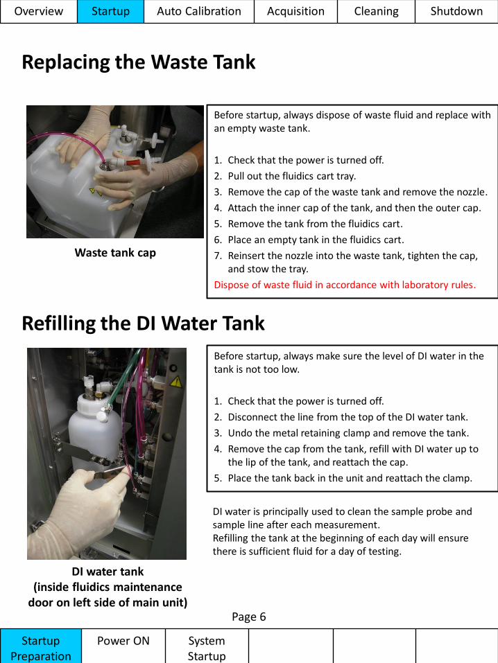
DI water tank (inside fluidics maintenance
door on left side of main unit)
Before startup, always make sure the level of DI water in the tank is not too low.
1. Check that the power is turned off.
2. Disconnect the line from the top of the DI water tank.
3. Undo the metal retaining clamp and remove the tank.
4. Remove the cap from the tank, refill with DI water up to the lip of the tank, and reattach the cap.
5. Place the tank back in the unit and reattach the clamp.
Refilling the DI Water Tank
Startup Preparation
Power ON System Startup
Waste tank cap
Before startup, always dispose of waste fluid and replace with an empty waste tank.
1. Check that the power is turned off.
2. Pull out the fluidics cart tray.
3. Remove the cap of the waste tank and remove the nozzle.
4. Attach the inner cap of the tank, and then the outer cap.
5. Remove the tank from the fluidics cart.
6. Place an empty tank in the fluidics cart.
7. Reinsert the nozzle into the waste tank, tighten the cap, and stow the tray.
Dispose of waste fluid in accordance with laboratory rules.
Replacing the Waste Tank
DI water is principally used to clean the sample probe and sample line after each measurement. Refilling the tank at the beginning of each day will ensure there is sufficient fluid for a day of testing.
Overview Startup Auto Calibration Acquisition Cleaning Shutdown
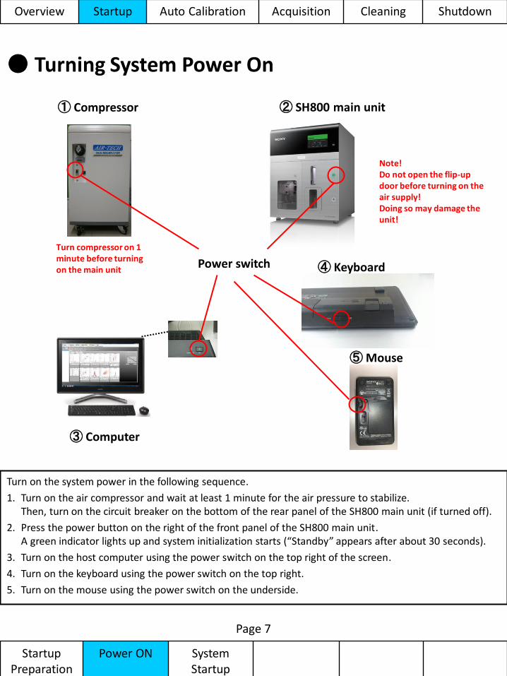
● Turning System Power On
Turn on the system power in the following sequence.
1. Turn on the air compressor and wait at least 1 minute for the air pressure to stabilize. Then, turn on the circuit breaker on the bottom of the rear panel of the SH800 main unit (if turned off).
2. Press the power button on the right of the front panel of the SH800 main unit. A green indicator lights up and system initialization starts (“Standby” appears after about 30 seconds).
3. Turn on the host computer using the power switch on the top right of the screen.
4. Turn on the keyboard using the power switch on the top right.
5. Turn on the mouse using the power switch on the underside.
Page 7
② SH800 main unit
③ Computer
Power switch ④ Keyboard
⑤ Mouse
Startup Preparation
Power ON System Startup
① Compressor
Turn compressor on 1 minute before turning on the main unit
Note! Do not open the flip-up door before turning on the air supply! Doing so may damage the unit!
Overview Startup Auto Calibration Acquisition Cleaning Shutdown
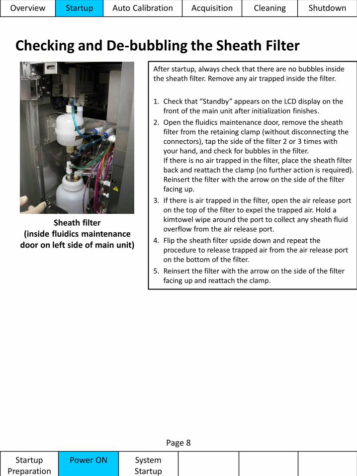
Checking and De-bubbling the Sheath Filter
After startup, always check that there are no bubbles inside the sheath filter. Remove any air trapped inside the filter.
1. Check that “Standby” appears on the LCD display on the front of the main unit after initialization finishes.
2. Open the fluidics maintenance door, remove the sheath filter from the retaining clamp (without disconnecting the connectors), tap the side of the filter 2 or 3 times with your hand, and check for bubbles in the filter. If there is no air trapped in the filter, place the sheath filter back and reattach the clamp (no further action is required). Reinsert the filter with the arrow on the side of the filter facing up.
3. If there is air trapped in the filter, open the air release port on the top of the filter to expel the trapped air. Hold a kimtowel wipe around the port to collect any sheath fluid overflow from the air release port.
4. Flip the sheath filter upside down and repeat the procedure to release trapped air from the air release port on the bottom of the filter.
5. Reinsert the filter with the arrow on the side of the filter facing up and reattach the clamp.
Page 8
Sheath filter (inside fluidics maintenance
door on left side of main unit)
Overview Startup Auto Calibration Acquisition Cleaning Shutdown
Startup Preparation
Power ON System Startup
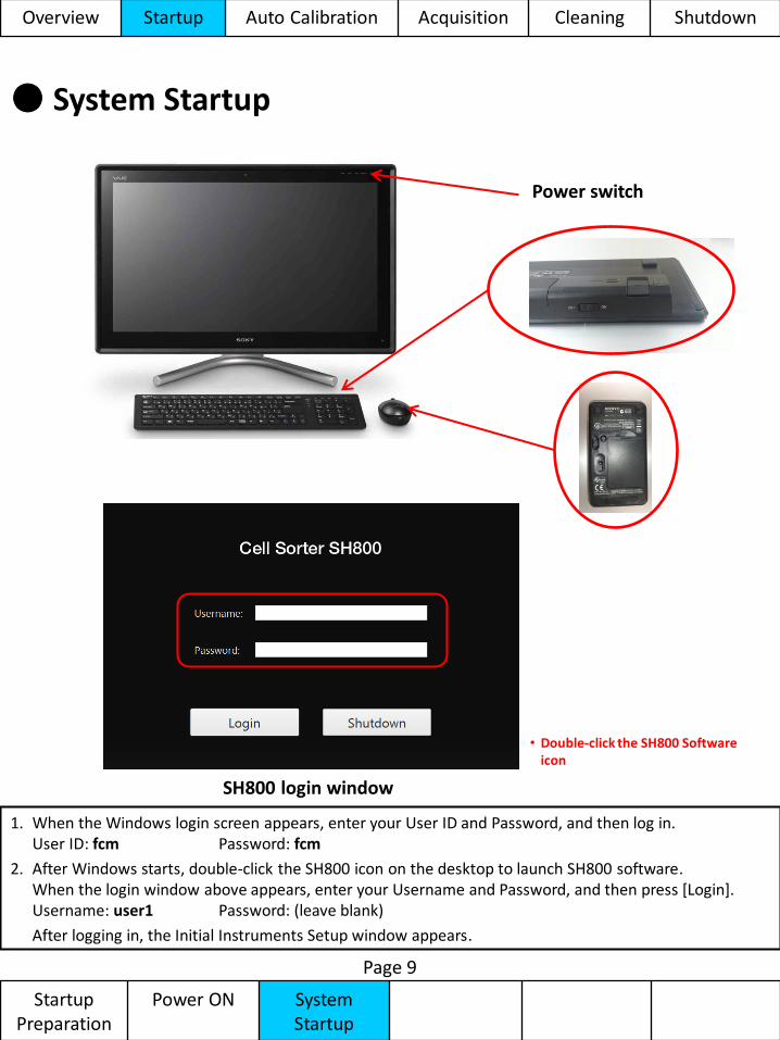
● System Startup
Page 9
SH800 login window
Startup Preparation
Power ON System Startup
Power switch
1. When the Windows login screen appears, enter your User ID and Password, and then log in. User ID: fcm Password: fcm
2. After Windows starts, double-click the SH800 icon on the desktop to launch SH800 software. When the login window above appears, enter your Username and Password, and then press [Login]. Username: user1 Password: (leave blank)
After logging in, the Initial Instruments Setup window appears.
• Double-click the SH800 Software icon
Overview Startup Auto Calibration Acquisition Cleaning Shutdown
Chip Detect and Load
Laser Select Optical Filter Check
Auto Calibration
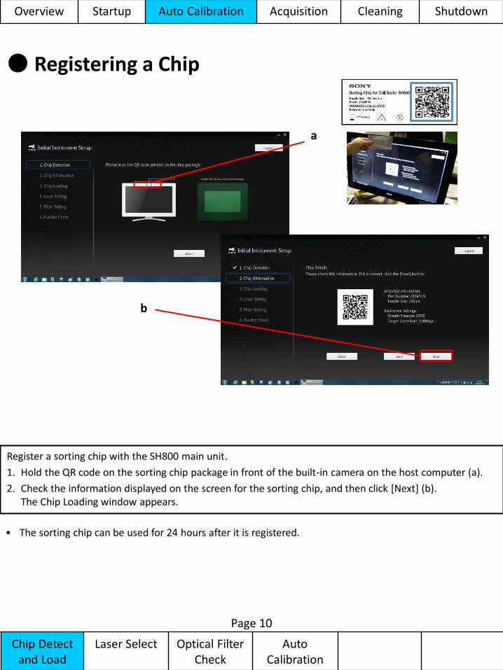
● Registering a Chip
a
b
Register a sorting chip with the SH800 main unit.
1. Hold the QR code on the sorting chip package in front of the built-in camera on the host computer (a).
2. Check the information displayed on the screen for the sorting chip, and then click [Next] (b). The Chip Loading window appears.
Page 10
Overview Startup Auto Calibration Acquisition Cleaning Shutdown
• The sorting chip can be used for 24 hours after it is registered.
Chip Detect and Load
Laser Select Optical Filter Check
Auto Calibration
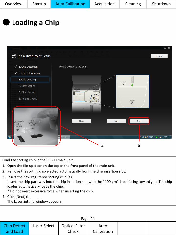
● Loading a Chip
b
Load the sorting chip in the SH800 main unit.
1. Open the flip-up door on the top of the front panel of the main unit.
2. Remove the sorting chip ejected automatically from the chip insertion slot.
3. Insert the new registered sorting chip (a). Insert the chip part-way into the chip insertion slot with the “100 µm” label facing toward you. The chip loader automatically loads the chip. * Do not exert excessive force when inserting the chip.
4. Click [Next] (b). The Laser Setting window appears.
a
Page 11
Overview Startup Auto Calibration Acquisition Cleaning Shutdown
Chip Detect and Load
Laser Select Optical Filter Check
Auto Calibration
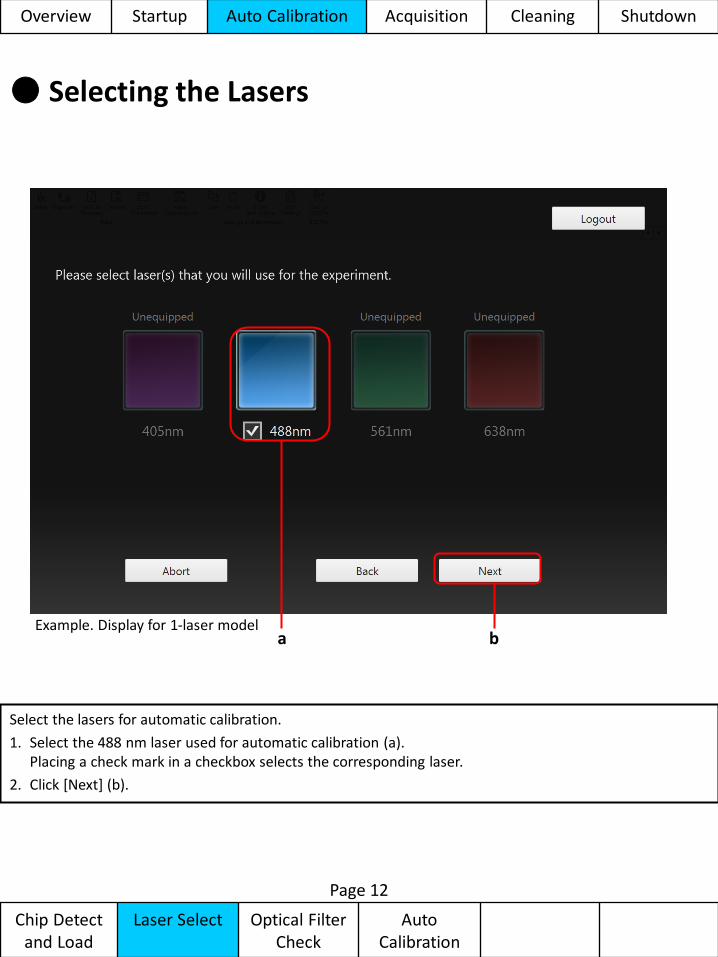
● Selecting the Lasers
a b
Select the lasers for automatic calibration.
1. Select the 488 nm laser used for automatic calibration (a). Placing a check mark in a checkbox selects the corresponding laser.
2. Click [Next] (b).
Page 12
Example. Display for 1-laser model
Overview Startup Auto Calibration Acquisition Cleaning Shutdown
Chip Detect and Load
Laser Select Optical Filter Check
Auto Calibration
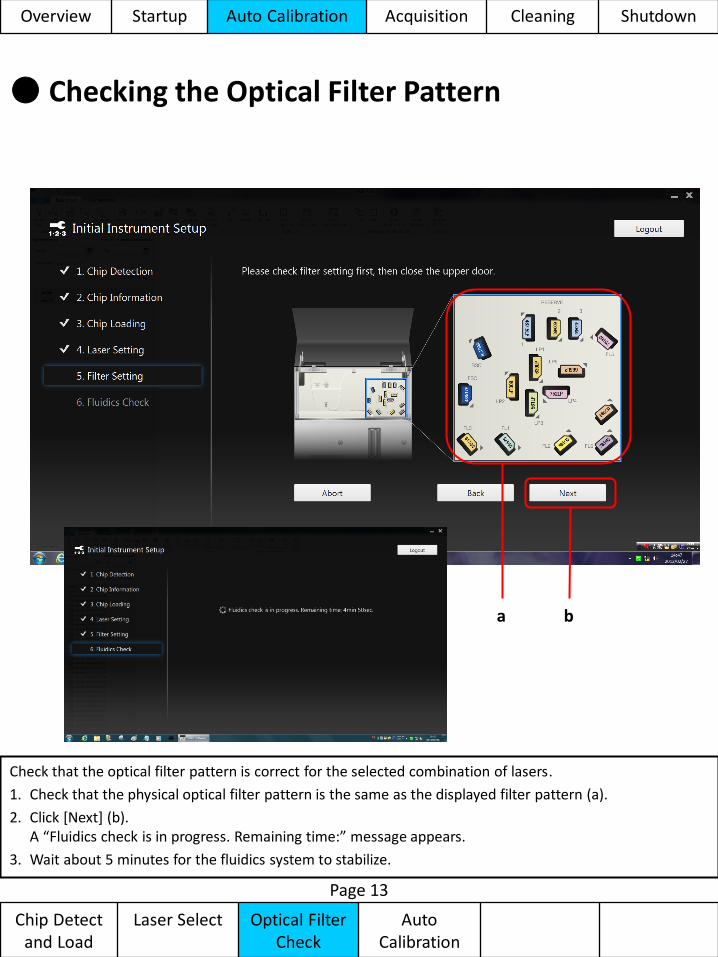
● Checking the Optical Filter Pattern
a b
Check that the optical filter pattern is correct for the selected combination of lasers.
1. Check that the physical optical filter pattern is the same as the displayed filter pattern (a).
2. Click [Next] (b). A “Fluidics check is in progress. Remaining time:” message appears.
3. Wait about 5 minutes for the fluidics system to stabilize.
Page 13
Overview Startup Auto Calibration Acquisition Cleaning Shutdown
Chip Detect and Load
Laser Select Optical Filter Check
Auto Calibration
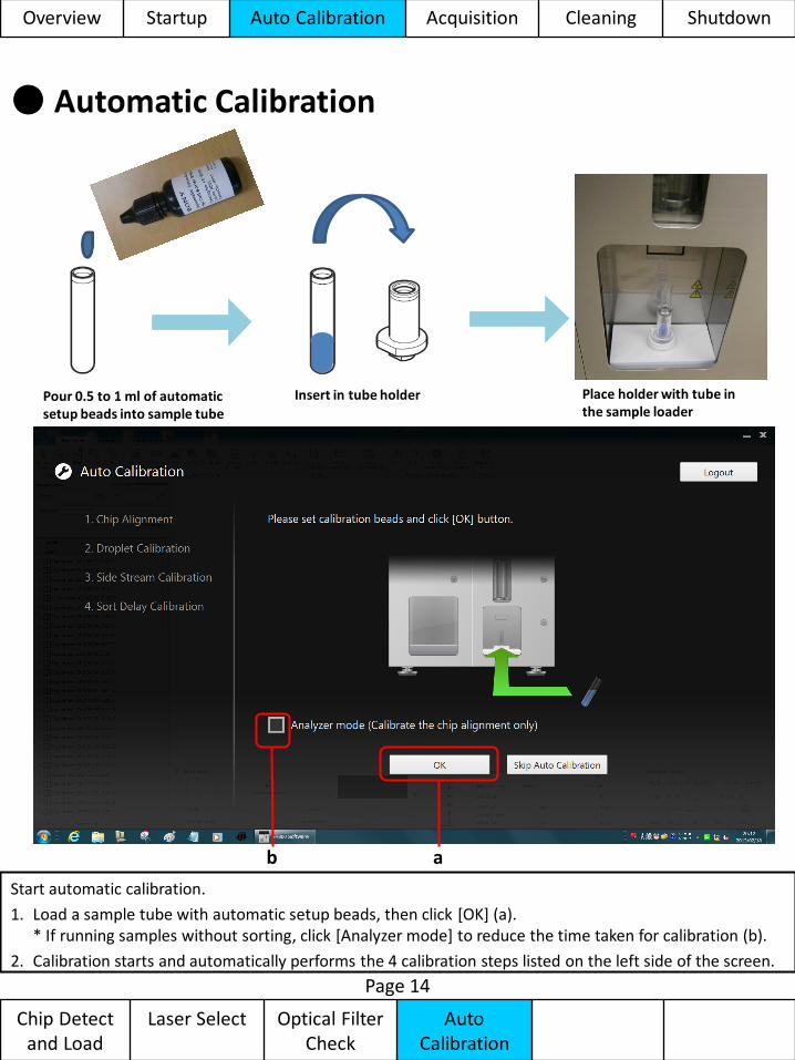
● Automatic Calibration
Pour 0.5 to 1 ml of automatic setup beads into sample tube
Insert in tube holder Place holder with tube in the sample loader
a
Start automatic calibration.
1. Load a sample tube with automatic setup beads, then click [OK] (a). * If running samples without sorting, click [Analyzer mode] to reduce the time taken for calibration (b).
2. Calibration starts and automatically performs the 4 calibration steps listed on the left side of the screen.
Page 14
b
Overview Startup Auto Calibration Acquisition Cleaning Shutdown
Chip Detect and Load
Laser Select Optical Filter Check
Auto Calibration
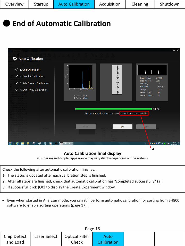
● End of Automatic Calibration
Check the following after automatic calibration finishes.
1. The status is updated after each calibration step is finished.
2. After all steps are finished, check that automatic calibration has “completed successfully” (a).
3. If successful, click [OK] to display the Create Experiment window.
Auto Calibration final display (Histogram and droplet appearance may vary slightly depending on the system)
Page 15
a
• Even when started in Analyzer mode, you can still perform automatic calibration for sorting from SH800 software to enable sorting operations (page 17).
Overview Startup Auto Calibration Acquisition Cleaning Shutdown
● Creating an Experiment
Page 16
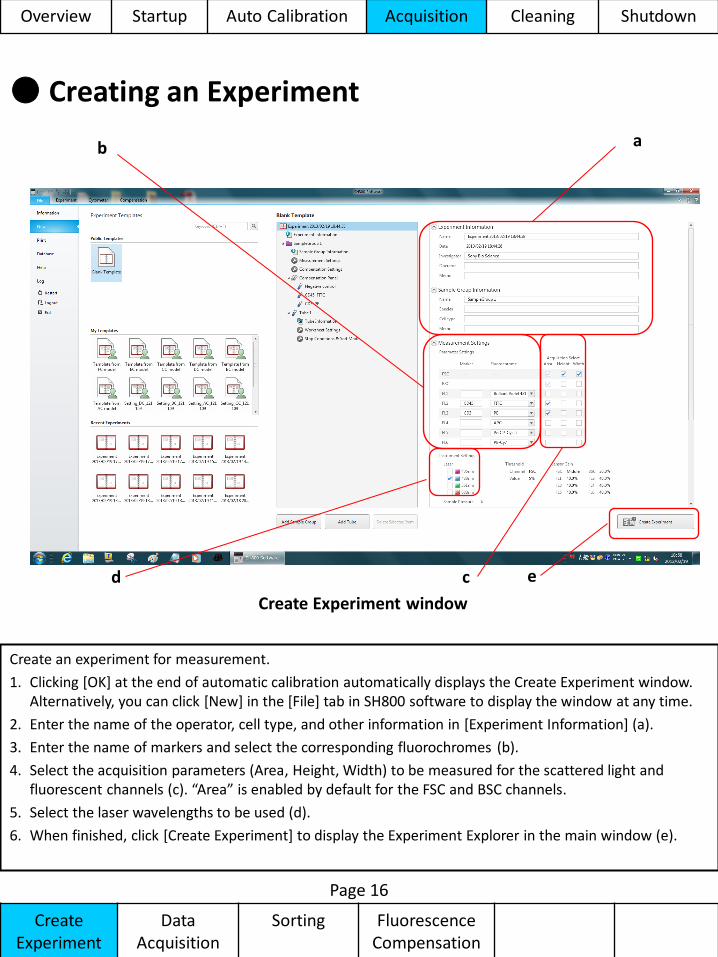
Create an experiment for measurement.
1. Clicking [OK] at the end of automatic calibration automatically displays the Create Experiment window. Alternatively, you can click [New] in the [File] tab in SH800 software to display the window at any time.
2. Enter the name of the operator, cell type, and other information in [Experiment Information] (a).
3. Enter the name of markers and select the corresponding fluorochromes (b).
4. Select the acquisition parameters (Area, Height, Width) to be measured for the scattered light and fluorescent channels (c). “Area” is enabled by default for the FSC and BSC channels.
5. Select the laser wavelengths to be used (d).
6. When finished, click [Create Experiment] to display the Experiment Explorer in the main window (e).
Create Experiment window
d
b a
c e
Create Experiment
Data Acquisition
Sorting Fluorescence Compensation
Overview Startup Auto Calibration Acquisition Cleaning Shutdown
● SH800 Software Overview
Page 17
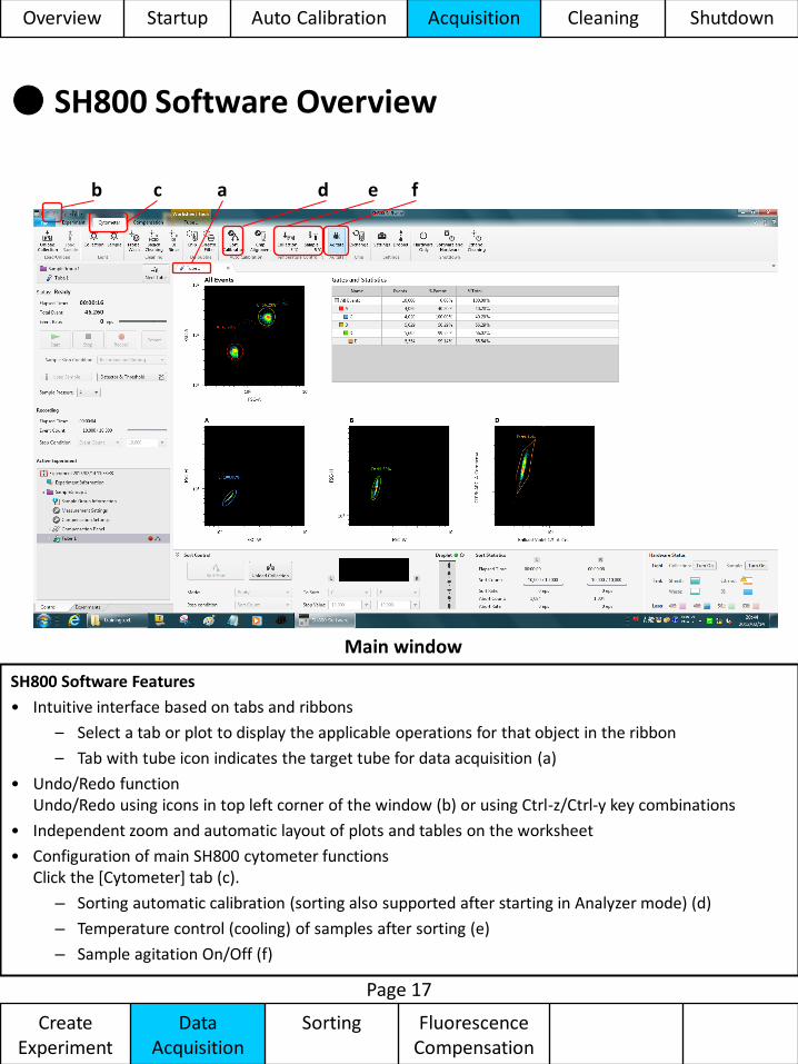
Main window
SH800 Software Features
• Intuitive interface based on tabs and ribbons
– Select a tab or plot to display the applicable operations for that object in the ribbon
– Tab with tube icon indicates the target tube for data acquisition (a)
• Undo/Redo function Undo/Redo using icons in top left corner of the window (b) or using Ctrl-z/Ctrl-y key combinations
• Independent zoom and automatic layout of plots and tables on the worksheet
• Configuration of main SH800 cytometer functions Click the [Cytometer] tab (c).
– Sorting automatic calibration (sorting also supported after starting in Analyzer mode) (d)
– Temperature control (cooling) of samples after sorting (e)
– Sample agitation On/Off (f)
b a c d e f
Overview Startup Auto Calibration Acquisition Cleaning Shutdown
Create Experiment
Data Acquisition
Sorting Fluorescence Compensation
● Configuring Data Acquisition Settings
Page 18
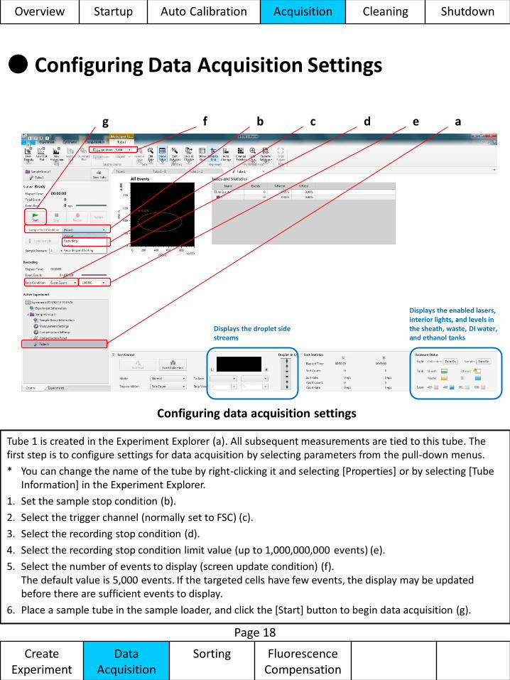
Configuring data acquisition settings
Tube 1 is created in the Experiment Explorer (a). All subsequent measurements are tied to this tube. The first step is to configure settings for data acquisition by selecting parameters from the pull-down menus.
* You can change the name of the tube by right-clicking it and selecting [Properties] or by selecting [Tube Information] in the Experiment Explorer.
1. Set the sample stop condition (b).
2. Select the trigger channel (normally set to FSC) (c).
3. Select the recording stop condition (d).
4. Select the recording stop condition limit value (up to 1,000,000,000 events) (e).
5. Select the number of events to display (screen update condition) (f). The default value is 5,000 events. If the targeted cells have few events, the display may be updated before there are sufficient events to display.
6. Place a sample tube in the sample loader, and click the [Start] button to begin data acquisition (g).
b c d e f g a
Displays the enabled lasers, interior lights, and levels in the sheath, waste, DI water, and ethanol tanks
Displays the droplet side streams
Overview Startup Auto Calibration Acquisition Cleaning Shutdown
Create Experiment
Data Acquisition
Sorting Fluorescence Compensation
● Modifying Data Acquisition Settings
Page 19
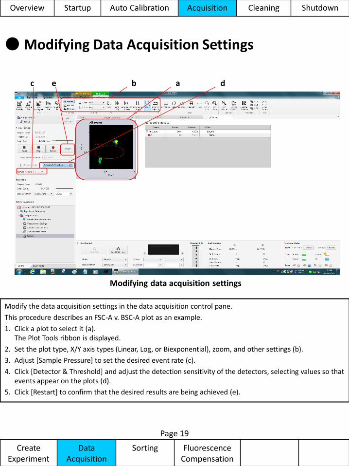
Modifying data acquisition settings
Modify the data acquisition settings in the data acquisition control pane.
This procedure describes an FSC-A v. BSC-A plot as an example.
1. Click a plot to select it (a). The Plot Tools ribbon is displayed.
2. Set the plot type, X/Y axis types (Linear, Log, or Biexponential), zoom, and other settings (b).
3. Adjust [Sample Pressure] to set the desired event rate (c).
4. Click [Detector & Threshold] and adjust the detection sensitivity of the detectors, selecting values so that events appear on the plots (d).
5. Click [Restart] to confirm that the desired results are being achieved (e).
a b d e c
Overview Startup Auto Calibration Acquisition Cleaning Shutdown
Create Experiment
Data Acquisition
Sorting Fluorescence Compensation
● Gating Acquired Data
Page 20
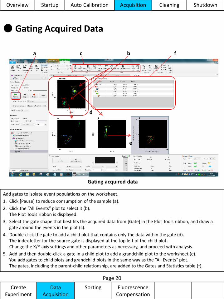
Gating acquired data
Add gates to isolate event populations on the worksheet.
1. Click [Pause] to reduce consumption of the sample (a).
2. Click the “All Events” plot to select it (b). The Plot Tools ribbon is displayed.
3. Select the gate shape that best fits the acquired data from [Gate] in the Plot Tools ribbon, and draw a gate around the events in the plot (c).
4. Double-click the gate to add a child plot that contains only the data within the gate (d). The index letter for the source gate is displayed at the top left of the child plot. Change the X/Y axis settings and other parameters as necessary, and proceed with analysis.
5. Add and then double-click a gate in a child plot to add a grandchild plot to the worksheet (e). You add gates to child plots and grandchild plots in the same way as the “All Events” plot. The gates, including the parent-child relationship, are added to the Gates and Statistics table (f).
b c a
d
e
f
Overview Startup Auto Calibration Acquisition Cleaning Shutdown
Create Experiment
Data Acquisition
Sorting Fluorescence Compensation
● Acquiring Data
Page 21
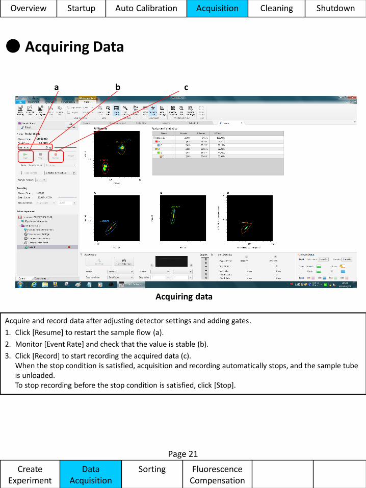
Acquiring data
Acquire and record data after adjusting detector settings and adding gates.
1. Click [Resume] to restart the sample flow (a).
2. Monitor [Event Rate] and check that the value is stable (b).
3. Click [Record] to start recording the acquired data (c). When the stop condition is satisfied, acquisition and recording automatically stops, and the sample tube is unloaded. To stop recording before the stop condition is satisfied, click [Stop].
c a b
Overview Startup Auto Calibration Acquisition Cleaning Shutdown
Create Experiment
Data Acquisition
Sorting Fluorescence Compensation
● Configuring Sorting
Page 22
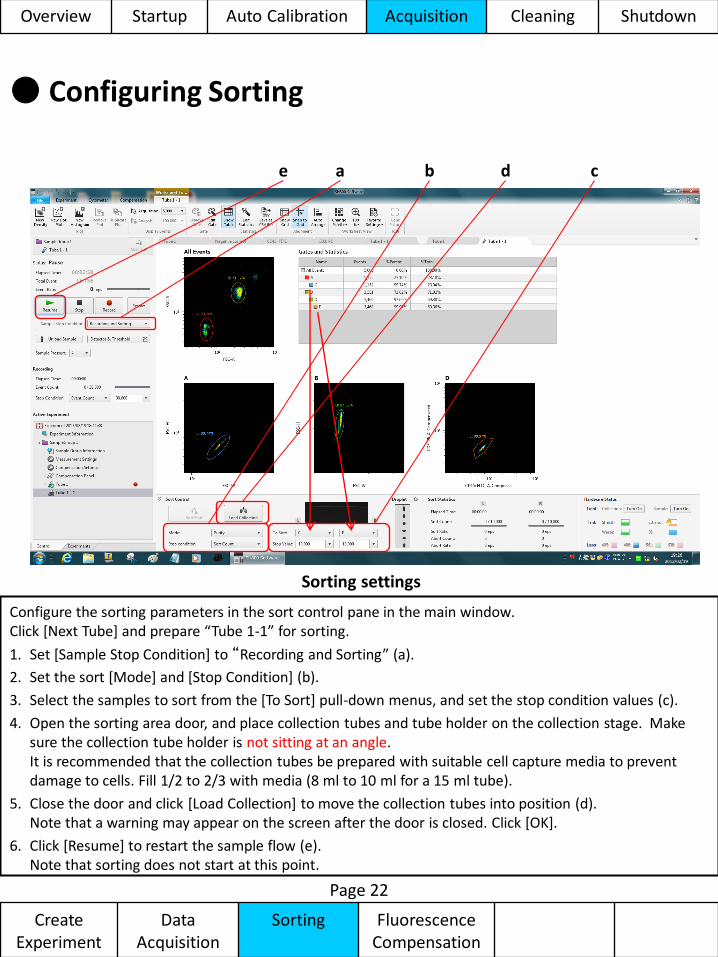
Sorting settings
Configure the sorting parameters in the sort control pane in the main window. Click [Next Tube] and prepare “Tube 1-1” for sorting.
1. Set [Sample Stop Condition] to “Recording and Sorting” (a).
2. Set the sort [Mode] and [Stop Condition] (b).
3. Select the samples to sort from the [To Sort] pull-down menus, and set the stop condition values (c).
4. Open the sorting area door, and place collection tubes and tube holder on the collection stage. Make sure the collection tube holder is not sitting at an angle. It is recommended that the collection tubes be prepared with suitable cell capture media to prevent damage to cells. Fill 1/2 to 2/3 with media (8 ml to 10 ml for a 15 ml tube).
5. Close the door and click [Load Collection] to move the collection tubes into position (d). Note that a warning may appear on the screen after the door is closed. Click [OK].
6. Click [Resume] to restart the sample flow (e). Note that sorting does not start at this point.
c b a e d
Overview Startup Auto Calibration Acquisition Cleaning Shutdown
Create Experiment
Data Acquisition
Sorting Fluorescence Compensation
● Starting Sorting
Page 23
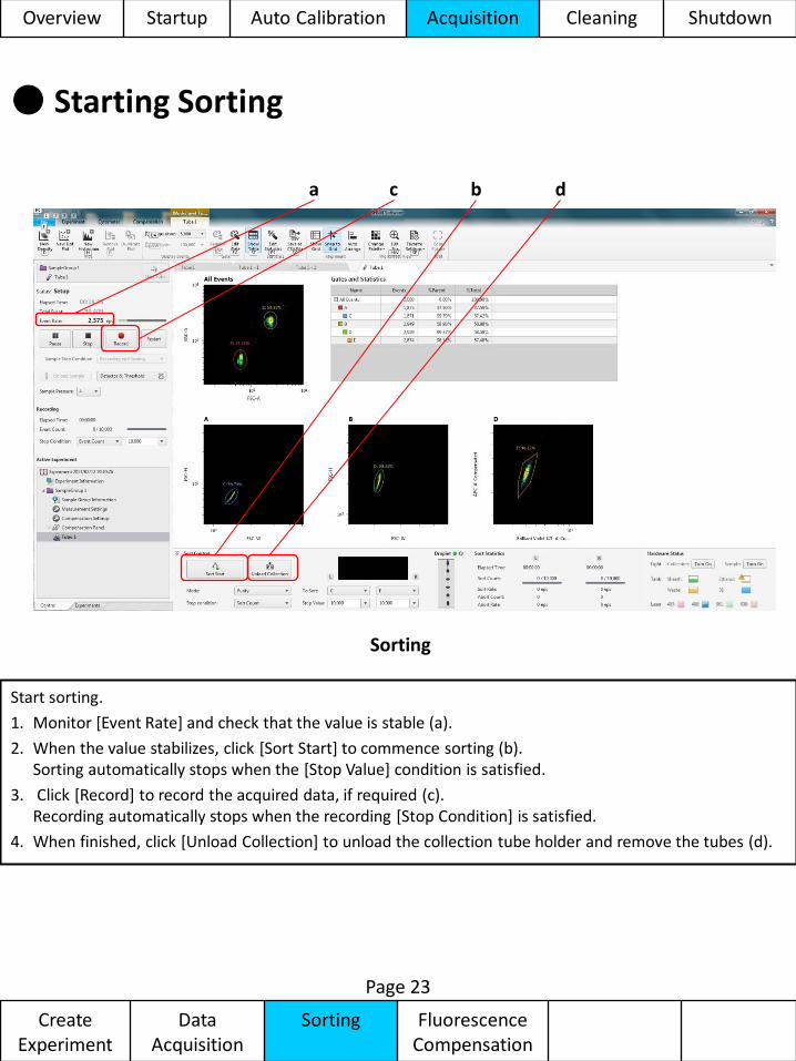
Sorting
Start sorting.
1. Monitor [Event Rate] and check that the value is stable (a).
2. When the value stabilizes, click [Sort Start] to commence sorting (b). Sorting automatically stops when the [Stop Value] condition is satisfied.
3. Click [Record] to record the acquired data, if required (c). Recording automatically stops when the recording [Stop Condition] is satisfied.
4. When finished, click [Unload Collection] to unload the collection tube holder and remove the tubes (d).
b a d c
Overview Startup Auto Calibration Acquisition Cleaning Shutdown
Create Experiment
Data Acquisition
Sorting Fluorescence Compensation
● Reference: Verifying Purity
Page 24
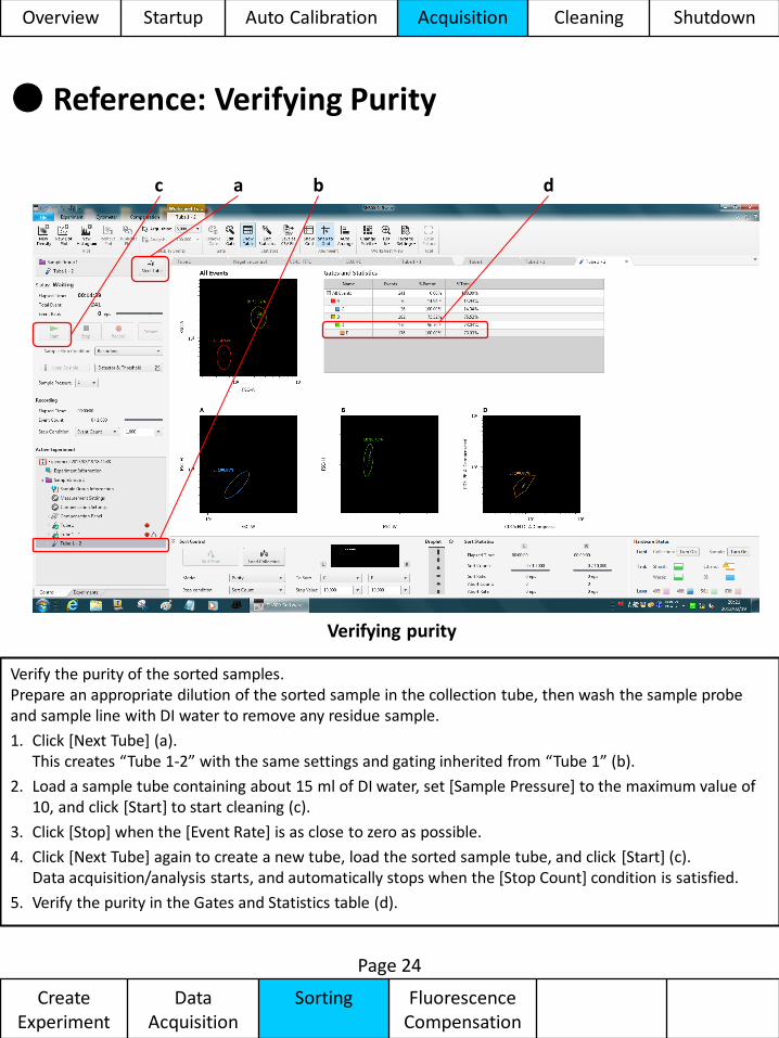
Verifying purity
Verify the purity of the sorted samples. Prepare an appropriate dilution of the sorted sample in the collection tube, then wash the sample probe and sample line with DI water to remove any residue sample.
1. Click [Next Tube] (a). This creates “Tube 1-2” with the same settings and gating inherited from “Tube 1” (b).
2. Load a sample tube containing about 15 ml of DI water, set [Sample Pressure] to the maximum value of 10, and click [Start] to start cleaning (c).
3. Click [Stop] when the [Event Rate] is as close to zero as possible.
4. Click [Next Tube] again to create a new tube, load the sorted sample tube, and click [Start] (c). Data acquisition/analysis starts, and automatically stops when the [Stop Count] condition is satisfied.
5. Verify the purity in the Gates and Statistics table (d).
b c d a
Overview Startup Auto Calibration Acquisition Cleaning Shutdown
Create Experiment
Data Acquisition
Sorting Fluorescence Compensation
● Adjusting Compensation (start wizard)
Page 25
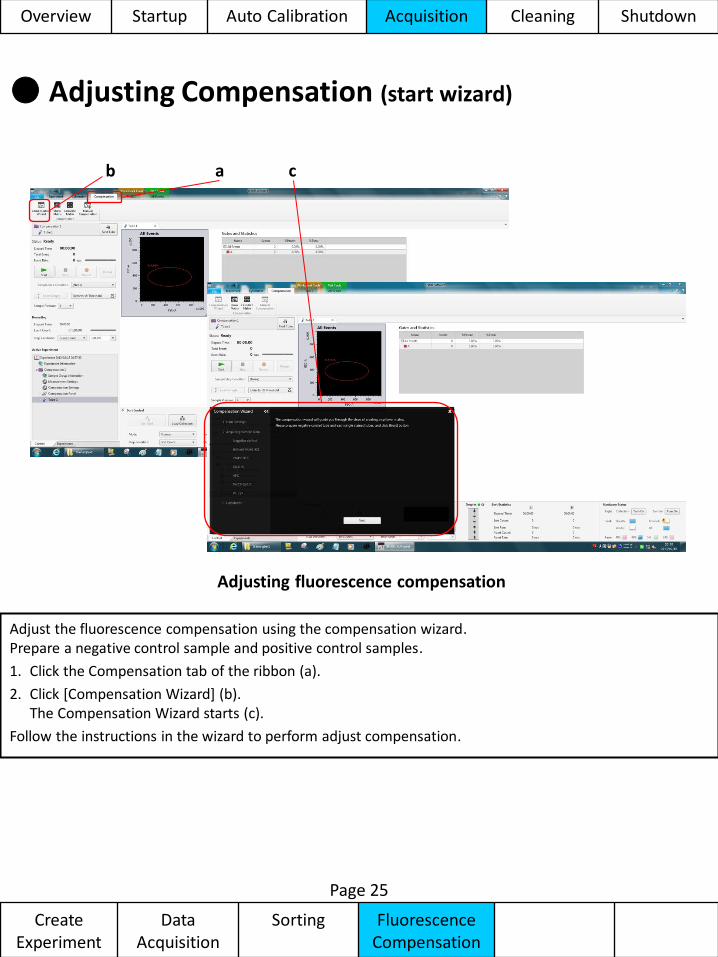
Adjusting fluorescence compensation
Adjust the fluorescence compensation using the compensation wizard. Prepare a negative control sample and positive control samples.
1. Click the Compensation tab of the ribbon (a).
2. Click [Compensation Wizard] (b). The Compensation Wizard starts (c).
Follow the instructions in the wizard to perform adjust compensation.
c b a
Overview Startup Auto Calibration Acquisition Cleaning Shutdown
Create Experiment
Data Acquisition
Sorting Fluorescence Compensation
● Adjusting Compensation (negative gain)
Page 26
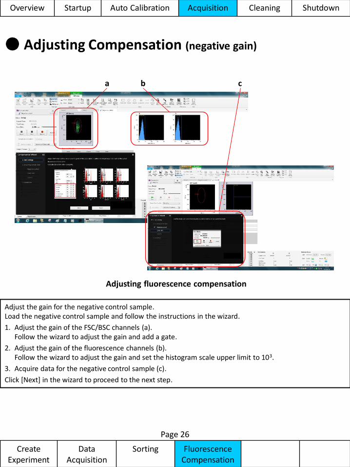
Adjusting fluorescence compensation
Adjust the gain for the negative control sample. Load the negative control sample and follow the instructions in the wizard.
1. Adjust the gain of the FSC/BSC channels (a). Follow the wizard to adjust the gain and add a gate.
2. Adjust the gain of the fluorescence channels (b). Follow the wizard to adjust the gain and set the histogram scale upper limit to 103.
3. Acquire data for the negative control sample (c).
Click [Next] in the wizard to proceed to the next step.
b a c
Overview Startup Auto Calibration Acquisition Cleaning Shutdown
Create Experiment
Data Acquisition
Sorting Fluorescence Compensation
● Adjusting Compensation (positive fluorescence)
Page 27
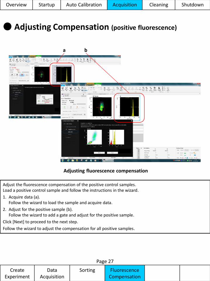
Adjusting fluorescence compensation
Adjust the fluorescence compensation of the positive control samples. Load a positive control sample and follow the instructions in the wizard.
1. Acquire data (a). Follow the wizard to load the sample and acquire data.
2. Adjust for the positive sample (b). Follow the wizard to add a gate and adjust for the positive sample.
Click [Next] to proceed to the next step.
Follow the wizard to adjust the compensation for all positive samples.
b a
Overview Startup Auto Calibration Acquisition Cleaning Shutdown
Create Experiment
Data Acquisition
Sorting Fluorescence Compensation
● Adjusting Compensation (calculate matrix)
Page 28
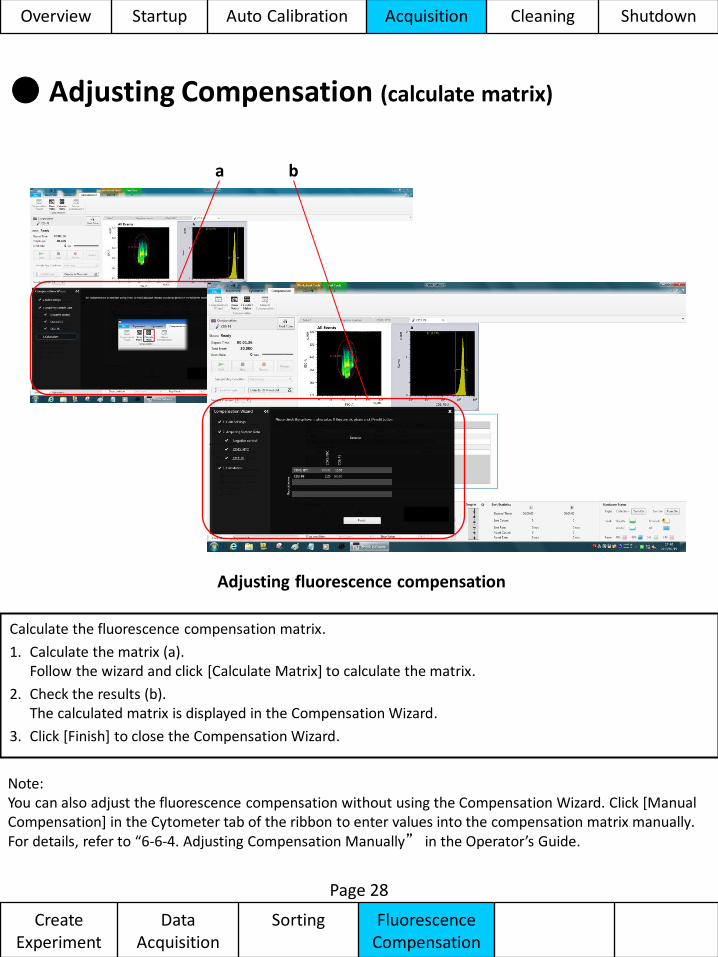
Adjusting fluorescence compensation
Calculate the fluorescence compensation matrix.
1. Calculate the matrix (a). Follow the wizard and click [Calculate Matrix] to calculate the matrix.
2. Check the results (b). The calculated matrix is displayed in the Compensation Wizard.
3. Click [Finish] to close the Compensation Wizard.
b a
Note: You can also adjust the fluorescence compensation without using the Compensation Wizard. Click [Manual Compensation] in the Cytometer tab of the ribbon to enter values into the compensation matrix manually. For details, refer to “6-6-4. Adjusting Compensation Manually” in the Operator’s Guide.
Overview Startup Auto Calibration Acquisition Cleaning Shutdown
Create Experiment
Data Acquisition
Sorting Fluorescence Compensation
● Cleaning the Sample Line (Bleach Cleaning)
Page 29
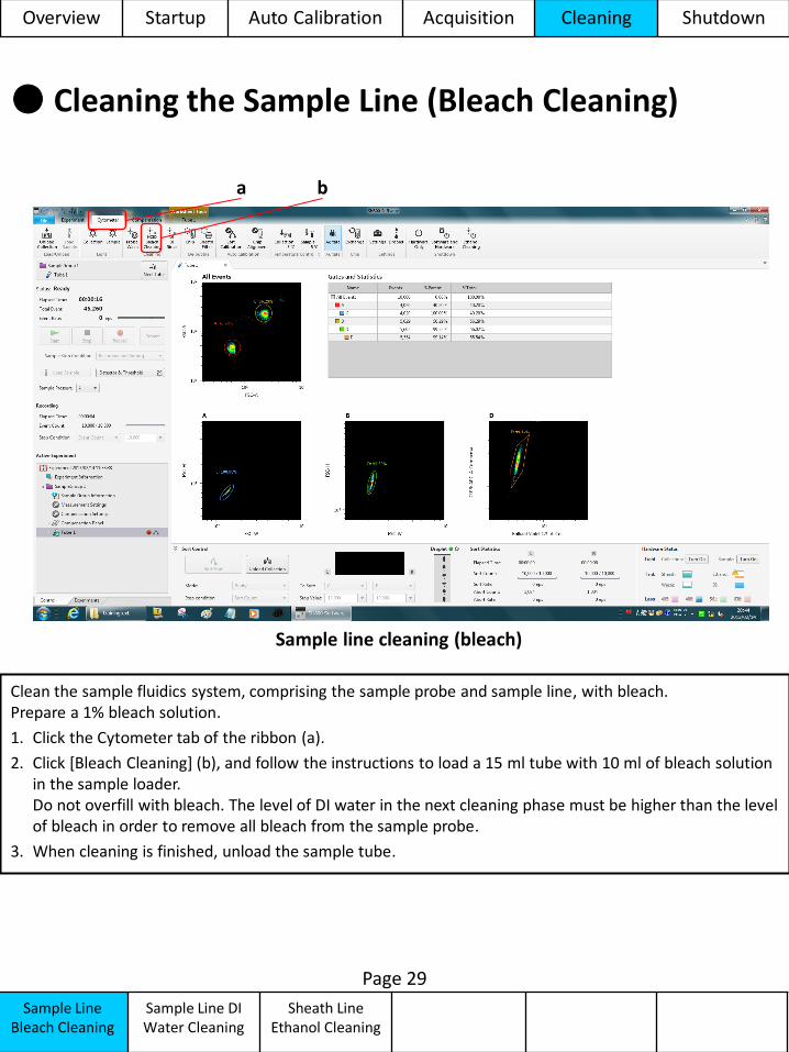
Sample line cleaning (bleach)
Clean the sample fluidics system, comprising the sample probe and sample line, with bleach. Prepare a 1% bleach solution.
1. Click the Cytometer tab of the ribbon (a).
2. Click [Bleach Cleaning] (b), and follow the instructions to load a 15 ml tube with 10 ml of bleach solution in the sample loader. Do not overfill with bleach. The level of DI water in the next cleaning phase must be higher than the level of bleach in order to remove all bleach from the sample probe.
3. When cleaning is finished, unload the sample tube.
b a
Sample Line Bleach Cleaning
Sample Line DI Water Cleaning
Sheath Line Ethanol Cleaning
Overview Startup Auto Calibration Acquisition Cleaning Shutdown
● Cleaning the Sample Line (DI Water Cleaning)
Page 30
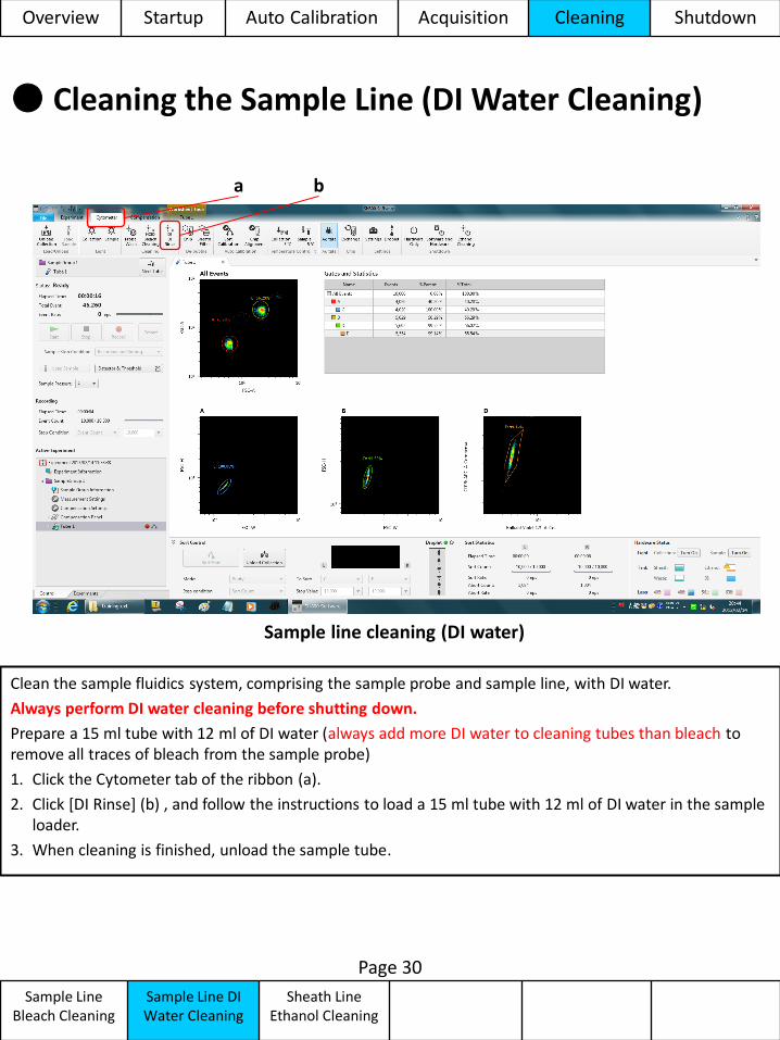
Sample line cleaning (DI water)
Clean the sample fluidics system, comprising the sample probe and sample line, with DI water.
Always perform DI water cleaning before shutting down.
Prepare a 15 ml tube with 12 ml of DI water (always add more DI water to cleaning tubes than bleach to remove all traces of bleach from the sample probe)
1. Click the Cytometer tab of the ribbon (a).
2. Click [DI Rinse] (b) , and follow the instructions to load a 15 ml tube with 12 ml of DI water in the sample loader.
3. When cleaning is finished, unload the sample tube.
b a
Overview Startup Auto Calibration Acquisition Cleaning Shutdown
Sample Line Bleach Cleaning
Sample Line DI Water Cleaning
Sheath Line Ethanol Cleaning
● Sheath Line Cleaning (Ethanol Cleaning)
Page 31
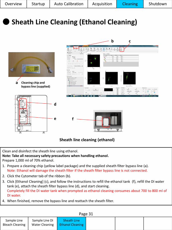
Clean and disinfect the sheath line using ethanol. Note: Take all necessary safety precautions when handling ethanol. Prepare 1,000 ml of 70% ethanol.
1. Prepare a cleaning chip (yellow label package) and the supplied sheath filter bypass line (a). Note: Ethanol will damage the sheath filter if the sheath filter bypass line is not connected.
2. Click the Cytometer tab of the ribbon (b).
3. Click [Ethanol Cleaning] (c), and follow the instructions to refill the ethanol tank (f), refill the DI water tank (e), attach the sheath filter bypass line (d), and start cleaning. Completely fill the DI water tank when prompted as ethanol cleaning consumes about 700 to 800 ml of DI water.
4. When finished, remove the bypass line and reattach the sheath filter.
c b
Cleaning chip and bypass line (supplied)
Sheath line cleaning (ethanol)
d
e f
Overview Startup Auto Calibration Acquisition Cleaning Shutdown
Sample Line Bleach Cleaning
Sample Line DI Water Cleaning
Sheath Line Ethanol Cleaning
a
● Shutting Down
Shutdown
Page 32
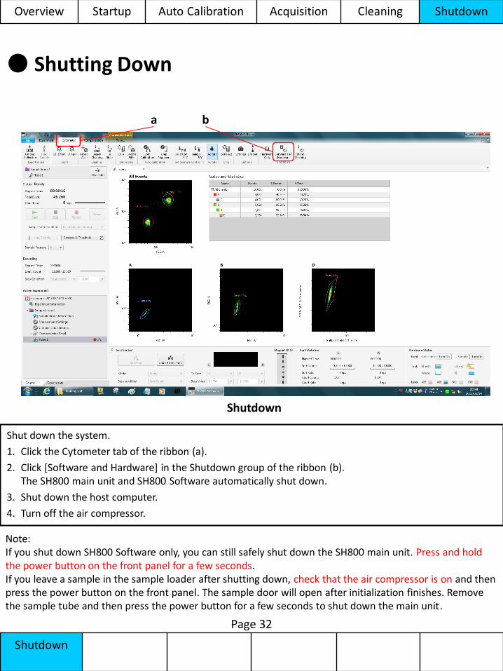
Shutdown
Shut down the system.
1. Click the Cytometer tab of the ribbon (a).
2. Click [Software and Hardware] in the Shutdown group of the ribbon (b). The SH800 main unit and SH800 Software automatically shut down.
3. Shut down the host computer.
4. Turn off the air compressor.
b a
Note: If you shut down SH800 Software only, you can still safely shut down the SH800 main unit. Press and hold the power button on the front panel for a few seconds. If you leave a sample in the sample loader after shutting down, check that the air compressor is on and then press the power button on the front panel. The sample door will open after initialization finishes. Remove the sample tube and then press the power button for a few seconds to shut down the main unit.
Overview Startup Auto Calibration Acquisition Cleaning Shutdown
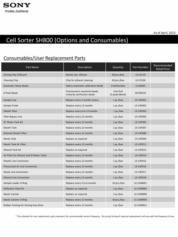
Part Name Description Quantity Part Number Recommended
Retail Price
Sorting Chip (100 µm) Nozzle size: 100 µm 40 pcs./box LE-C3110
Cleaning Chip Chip for ethanol cleaning 40 pcs./box LE-C3100
Automatic Setup Beads Optics automatic calibration beads 3 bottles/box LE-B3001
6-Peak Beads Fluorescence sensitivity beads Linearity verification beads
2ml+3ml (5-peak+Blank)
AE700520
Sample Line Replace every 3 months (max.) 1 pc./box LE-U3F001
Sample Probe Replace every 12 months 1 pc./box LE-U3F002
Sheath Filter Replace every 6 to 12 months 1 pc./box LE-U3F003
Filter Bypass Line Replace every 12 months 1 pc./box LE-U3F004
DI Water Tank Kit Replace every 12 months 1 pc./box LE-U3F005
Sheath Tank Replace every 12 months 1 pc./box LE-U3F007
Sintered Sheath Filter Replace every 12 months 1 pc./box LE-U3F008
Waste Tank Replace as required 1 pc./box LE-U3F009
Waste Tank Air Filter Replace every 12 months 1 pc./box LE-U3F011
Ethanol Tank Kit Replace as required 1 pc./box LE-U3F012
Air Filter for Ethanol and DI Water Tanks Replace every 12 months 1 pc./box LE-U3F014
Sheath Line Connection Replace every 12 months 1 pc./box LE-U3F015
Pressurized Air Line Connection Replace every 12 months 1 pc./box LE-U3F016
Waste Line Connection Replace every 12 months 1 pc./box LE-U3F017
Ethanol Line Connection Replace every 12 months 1 pc./box LE-U3F018
Sample Loader O-Ring Replace every 3 to 6 months 10 pcs./box LE-U3M001
Deflection Plate Kit Replace as required 1 pc./box LE-U3M006
Waste Catcher Replace as required 1 pc./box LE-U3M008
Waste Catcher O-Ring Replace every 12 months 10 pcs./box LE-U3M009
Rubber Packing for Sorting Area Door Replace every 12 months 1 pc./box LE-U3M012
Consumables/User Replacement Parts
Cell Sorter SH800 (Options and Consumables)
As of April, 2013
* The schedule for user replacement parts represent the recommended service frequency. The actual timing of required replacement will vary with the frequency of use.
Sony and its logo, Sony Biotechnology Inc., and iCyt are trademarks of Sony Corporation. Alexa Fluor® and Pacific Blue™ are registered trademarks of and licensed under patents assigned to Life Technologies Corporation. Cy and CyDye are trademarks of GE Healthcare Limited. Sony Biotechnology Inc. products containing Cy5, Cy5.5 or Cy7 are manufactured under license from GE Healthcare under U.S. Patent Numbers 5,569,587; 5,627,027 and patents or pending applications that are continuations, continuations-in-part, re-examinations, divisionals, reissues or foreign equivalents thereof. Brilliant Violet dyes are trademark s of Sirigen Ltd. All other trademarks are the property of their respective owners..
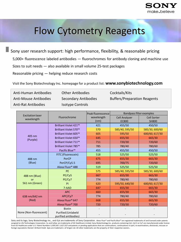
Flow Cytometry Reagents
5,000+ fluorescence labeled antibodies — fluorochromes for antibody cloning and machine use
Sizes to suit needs — also available in small volume 25-test packages
Reasonable pricing — helping reduce research costs
Visit the Sony Biotechnology Inc. homepage for a product list: www.sonybiotechnology.com
Sony user research support: high performance, flexibility, & reasonable pricing
Excitation laser wavelength
Fluorochrome Peak fluorescence
wavelength (nm)
Bandpass filter examples
Cell Analyzer EC800
Cell Sorter SH800
405 nm (Purple)
Brilliant Violet 421™ 421 455/50 450/50
Brilliant Violet 570™ 570 585/40, 595/50 585/30, 600/60
Brilliant Violet 605™ 605 595/50 600/60, 617/30
Brilliant Violet 650™ 645 655/30 665/30
Brilliant Violet 711™ 711 720/30 720/60
Brilliant Violet 785™ 785 780/40 780/60
Pacific Blue™ 455 455/50 450/50
488 nm (Blue)
FITC (Fluorescein) 518 525/50 525/50
PerCP 675 655/30 665/30
PerCP/Cy5.5 695 700/75 720/60
Alexa Fluor® 488 519 525/50 525/50
488 nm (Blue) or
561 nm (Green)
PE 575 585/40, 595/50 585/30, 600/60
PE/Cy5 667 655/30 665/30
PE/Cy7 774 780/40 780/60
PI 620 595/50, 640/30 600/60, 617/30
7-AAD 647 655/30 665/30
638 nm/642 nm (Red)
APC 660 655/30 665/30
APC/Cy7 774 780/40 780/60
Alexa Fluor® 647 668 655/30 665/30
Alexa Fluor® 700 720 720/30 720/60
None (Non-fluorescent) Biotin - - -
Purified (Unlabeld purified antibodies)
- - -
Anti-Human Antibodies Other Antibodies Cocktails/Kits
Anti-Mouse Antibodies Secondary Antibodies Buffers/Preparation Reagents
Anti-Rat Antibodies Isotype Controls

For Research Use Only. Not for use in diagnostic or therapeutic procedures. This SH800 is classified as a Class 1 laser product.
US/International Japan Europe 2100 South Oak Street, 5-1-12 Kita-Shinagawa, Shinagawa-ku The Heights, Brooklands, Champaign, IL 61820, U.S.A Tokyo, 141-0001 Weybridge,Surrey, KT130XW, UK Voice: +1 800-275-5963 Voice: 0120-667-010 Voice: +44 (0)7795-490084 FAX: +1 217-328-9692 FAX: 0120-388-060 FAX: +44 (0)7795-490084 [email protected] [email protected] [email protected]