Embed Size (px)
Citation preview

Building Information Management and Modeling (BIM) & Facility Electronic Operations and Maintenance Support Information (eOMSI) Training
October 2015

2
Training Objectives
1. NAVFAC Phased BIM Implementation Plan
2. eOMSI Facility Data Workbook (FDW)
3. eOMSI/OMSI Specifications Package
4. FC 1-300-09N BIM Requirements

3
Phased BIM Implementation Plan
• BIM is a process that generates, collects and maintains data throughout the lifecycle of a facility
• NAVFAC’s BIM process began looking at software; but this was not THE solution
• Realizing software was not the answer, we began to look at facility lifecycle data requirements across the command

4
Phased BIM Implementation Plan

5
Phased BIM Implementation Plan
•We found that, during design and construction, Capital Improvements generated +90% of facility data to support Public Works’ facility lifecycle maintenance mission
•As a result of facility data mapping, NAVFAC’s BIM evolved into a collaboration between Capital Improvements and Public Works Business Lines
•This led to the development of our BIM Definition and BIM Goal

6
Phased BIM Implementation Plan
BIM Definition:•To develop a comprehensive strategy for collecting, managing, and sharing requireddata / information to accurately support facility life cycle from early planning to building disposal
BIM Goals:• Standardize data processes and data
format for facility life cycle sustainment• Data entered once, used repeatedly, used
consistently and maintained current

7
Phased BIM Implementation Plan
What BIM is for NAVFAC:•eOMSI Data Deliverables for facility life cycle sustainment, restoration and modernization (SRM)
•Part I: eOMSI Manuals:1) Product and Drawing Information
2) Facility Information
•Part II: eOMSI Facility Data Workbook (FDW)

8
Phased BIM Implementation Plan
What BIM is Not for NAVFAC:•A specific software solution e.g. REVIT, Bentley, etc.
•NAVFAC will not require industry to purchase specific software, BIM solution is vendor neutral for parametric modeling
•A modeling solution

9
Phased BIM Implementation Plan
Policy:
ECB 2014-01 - NAVFAC’s Building Information Management and Modeling (BIM) Phased Implementation Plan, October 2015
Purpose:Provide overall NAVFAC policy and guidanceon implementation of Building Information Management and Modeling (BIM) deliverables, roles, and responsibilities

10
Phased BIM Implementation Plan
Applicability (ECB 2014-01):Applies at all Navy Installations, Joint Bases, Department of
Defense (DoD) Agencies, or Field Activities where NAVFAC PW is the maintenance provider of the facility that meet the following requirements:
1) New construction greater than or equal to $1M2) Major renovation greater than or equal to 50% of the Plant
Replacement Value or greater than or equal to $3M3) In-House Design Bid Build (DBB) teams presently not
required to use BIM due to limited network capacity and capabilityDesign-Build (DB) projects require BIM & eOMSI
A/E Design-Bid-Build (DBB) projects require BIM & eOMSI
IH Design-Bid-Build (DBB) require eOMSI only

11
Phased BIM Implementation Plan
NAVFAC eOMSI:

12
Phased BIM Implementation Plan
3D Parametric Modeling Becomes Effective FY161. eOMSI Facility Data Workbook (FDW) - Excel workbook
which contains the Model & Facility Data Matrix (used to define Mastersystems, Systems and Subsystems included in the Model and associated Level of Detail (LOD)
2. BIM Project Execution Plan (PxP) – A quality control document for Design-Build projects completed by the DOR that identifies BIM objectives, goals, & modeling applications.
3. Facilities Criteria (FC) 1-300-09N NAVY AND MARINE CORPS DESIGN PROCEDURES – It contains definitions, minimum modeling requirements, submittals, & reviews for the DOR to follow during design of 3D parametric models. The FC 1-300-09N will be referenced in the Design-Build Request for Proposals (RFP)

13
Phased BIM Implementation Plan
eOMSI FDW(DOR, KTR & FMD/FMS)
BIM PxP(DOR)
FC 1-300-09N(DOR)
NAVFAC BIM:
14
Cost of eOMSI & BIM Deliverables• The implementation of eOMSI & BIM deliverables will not
increase the cost of doing business with NAVFAC:• A majority of A/E firms and construction contractors utilize
parametric modeling (since 2005); by NAVFAC implementing this technology it improves efficiencies between Gov’t & industry
• By formalizing 3D parametric modeling & facility data requirements, NAVFAC standardizes electronic deliverables across the command for industry to incorporate
• Electronic Deliverables:• eOMSI Manuals – Current requirement, no cost impact• eOMSI Facility Data Workbook – Existing data KTR currently
provides Gov’t in a new format (spreadsheet), no cost impact• 3D parametric model - Industry standard, now a standard
NAVFAC Gov’t requirement, no cost impact

15
Phased BIM Implementation Plan
NAVFAC BIM/eOMSI pageis a WORK IN PROGRESS.
It is located at theWhole Building Design Guide
http://www.wbdg.org/bim/navfac_bim.php
Refer to this page for updates to our program

16
PW Expectations1. …This revision enables better life cycle management
and reduced total ownership costs of our facilities by improving the transition of facilities from CI to PW in the field… …The eOMSI Spec and FDW continue to be revised as we receive feedback from the field to improve our eOMSI/ Building Information Management & Modeling (BIM) process…
2. …The purpose of this letter is to emphasize the importance of continued cooperation between CI and PW in the field to enforce this specification and utilize the information during the design, construction, operations, and maintenance of our facilities; specifically inputting inventory data into Maximo. Inventory and data management in MAXIMO should not be considered as a new requirement…
3. …Please ensure your command's full support for this training and use of this improved eOMSI specification. We need to properly enforce eOMSI on our contracts, thoroughly review and accept the deliverables, and most importantly utilize the information effectively by incorporating inventory data into MAXIMO to support ongoing life cycle management….

17
You may start hearing “BIM” or “BIMM”
NAVFAC BIM page: http://www.wbdg.org/bim/navfac_bim.php
Building Information Management and Modeling(Building Information Management/Modeling)
Pronunciation: /bɪm/
1. (Industry Process, Acronym) A BIM is a shared knowledge resource for information about a facility forming a reliable basis for decisions during its life-cycle; defined as existing from earliest conception to demolition.
“Analogous to GIS, it is a facility level information system.”
Quick slide on BIM
What does BIM have to do with eOMSI and PW?
Everything&
Nothing
Starting FY16, CI will begin to utilize BIM to model new
projects and BIM will generate eOMSI data.
For the foreseeable future PW will not utilize the BIM
model, only the data.

18
eOMSIFacilities Management &
Sustainment
BIMDesign/Construction
Electronic Operation and Maintenance Support Information: Contractor provided facility asset information that helps the Facility User
and PWD Staff effectively Operate, Maintain and Repair a Facility.
What is eOMSI?
Information and data are provided in electronic format.
19
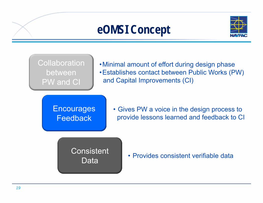
eOMSI Concept
Collaboration between
PW and CI
Encourages Feedback
Consistent Data
•Minimal amount of effort during design phase•Establishes contact between Public Works (PW)and Capital Improvements (CI)
• Gives PW a voice in the design process to provide lessons learned and feedback to CI
• Provides consistent verifiable data

20
eOMSI is process that connects CI and PW data streams. Standardization of this information will:
reduce duplicated efforts increase the accuracy and completeness of information reduce the total cost of ownership
eOMSI Concept
Provides information for the facility user and the Public Works staff to maintain and operate the facility
Data provided by the contractor during construction:• From facility information in design drawings and construction
submittals• From data gathered during field verification

21
New assets will be created in bulk. Time consuming manual entry not required.
Current State vs Future State How are we currently loading assets? Manually, one at a time as necessary
Labor intensive Higher opportunity for error
How will eOMSI make things better for PWD? Ensures that FMD/FMS is involved from the
beginning. Enables maintenance feedback to CI Strengthens communication
Ensures all assets are ID’edand properly uploaded
22
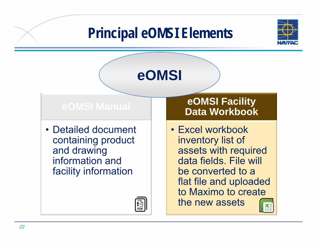
eOMSI Manual
• Detailed document containing product and drawing information and facility information
eOMSI Facility Data Workbook
• Excel workbook inventory list of assets with required data fields. File will be converted to a flat file and uploaded to Maximo to create the new assets
Principal eOMSI Elements
eOMSI
23
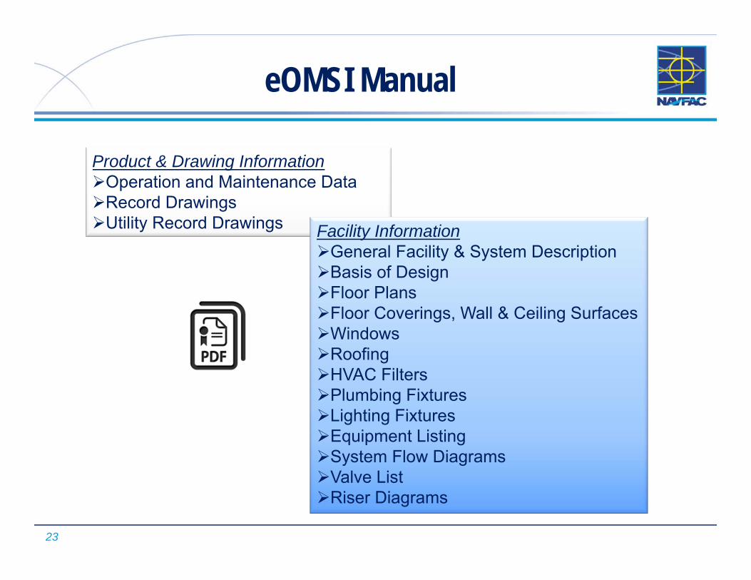
eOMSI Manual
Product & Drawing InformationOperation and Maintenance DataRecord DrawingsUtility Record Drawings Facility Information
General Facility & System DescriptionBasis of DesignFloor Plans Floor Coverings, Wall & Ceiling SurfacesWindowsRoofingHVAC FiltersPlumbing FixturesLighting FixturesEquipment ListingSystem Flow DiagramsValve ListRiser Diagrams

24
eOMSI Facility Data Workbook (FDW)
• DOR will select the Mastersystem, System and Subsystem data records during Design Phase
• Construction Contractor (KTR) will complete the records with the assistance of the government

25
What is eOMSI FDW?
•Excel Spreadsheet•Identifies Mastersystems, Systems and Subsystems of a Project
•Lists all Installed Assets for Facility•Easy To Use = YES
• If you can use Excel you can use the FDW•Living Project Document
• Never break up the tabs• Updated throughout the life of the Project from Design through BOD
26
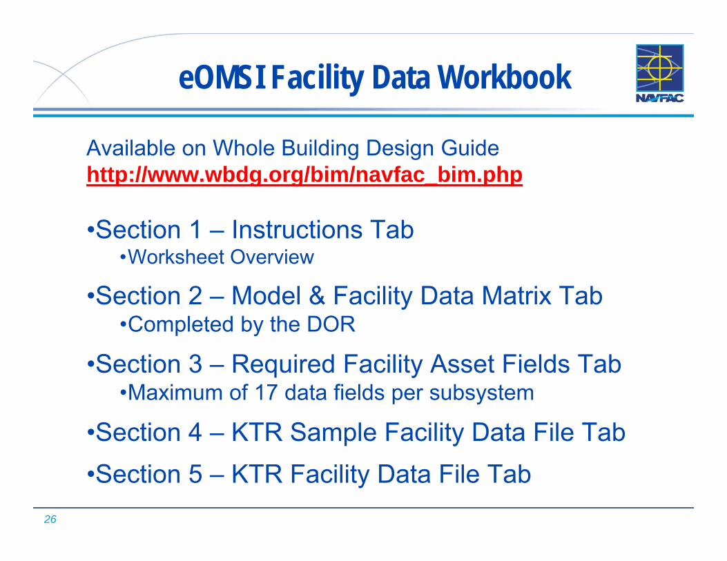
eOMSI Facility Data Workbook
Available on Whole Building Design Guide http://www.wbdg.org/bim/navfac_bim.php
•Section 1 – Instructions Tab•Worksheet Overview
•Section 2 – Model & Facility Data Matrix Tab•Completed by the DOR
•Section 3 – Required Facility Asset Fields Tab•Maximum of 17 data fields per subsystem
•Section 4 – KTR Sample Facility Data File Tab•Section 5 – KTR Facility Data File Tab

27
eOMSI Facility Data Workbook
Tab 1Instructions
Tab 2Model & Facility
Data Matrix(DOR)
Tab 3Required Facility
Asset Fields
Tab 4KTR Sample Facility
Data File
Tab 5KTR Facility Data
File (KTR)

28
General Workflow
•Design Phase:•Model & Facility Data Matrix Tab:
•DOR defines Mastersystems and Systems
•DOR (with FMD assistance) refines the Matrix by identifying the Mastersystems, Systems, Subsystems throughout Design Phase
•Construction Phase:•KTR Facility Data File Tab:
•KTR populates as equipment is installed & facility is built
•FMD Reviews eOMSI FDW and with CI CM field verifies a sample list of Mastersystems, Systems, & Subsystems
29
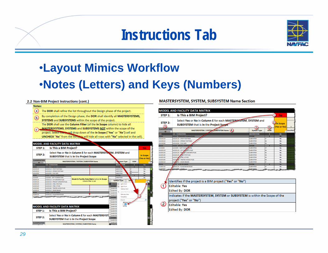
Instructions Tab
•Layout Mimics Workflow•Notes (Letters) and Keys (Numbers)

30
Model & Facility Data Matrix Tab
•Matrix Components•How to Use the Matrix
•Selecting Mastersystems, Systems and Subsystems
•Filtering out Unused Systems
•Who Is Responsible for the Matrix•DOR maintains the Matrix; coordinated with FMD/FMS
•What is the Matrix Used For?•1st step in defining eOMSI MAXIMO data
•Q/C check of design elements
•Specification cross check

31
eOMSI Facility Data Workbook
Description Listname UOMA10 ‐ FOUNDATIONS MASTERSYSTEM SFA20 ‐ BASEMENT CONSTRUCTION MASTERSYSTEM SFB10 ‐ SUPERSTRUCTURE MASTERSYSTEM SFB20 ‐ EXTERIOR ENCLOSURE MASTERSYSTEM SFB30 ‐ ROOFING MASTERSYSTEM SFC10 ‐ INTERIOR CONSTRUCTION MASTERSYSTEM SFC20 ‐ STAIRS MASTERSYSTEM RISERC30 ‐ INTERIOR FINISHES MASTERSYSTEM SFD10 ‐ CONVEYING MASTERSYSTEM EAD20 ‐ PLUMBING MASTERSYSTEM EAD30 ‐ HVAC MASTERSYSTEM EAD40 ‐ FIRE PROTECTION MASTERSYSTEM EAD50 ‐ ELECTRICAL MASTERSYSTEM EA
A10 – D50 Typical Mastersystems for Navy MCON (<5’),Major Renovation, or Facility Systems Replacement

32
eOMSI Facility Data Workbook
J10 – Q10 Typical Mastersystems for Utilities ProjectDescription Listname UOMJ10 ‐ Electric Utilities MASTERSYSTEM EAK10 ‐ Potable Water Utilities MASTERSYSTEM EAK20 ‐ Non‐Potable Water Utilities MASTERSYSTEM EAK30 ‐ Fire Protection Water Utilities MASTERSYSTEM EAK40 ‐ Salt Water Utilities MASTERSYSTEM EAL10 ‐ Steam Utilities MASTERSYSTEM EAL20 ‐ High Temp Hot Water Utilities MASTERSYSTEM EAL30 ‐ Domestic Hot Water Utilities MASTERSYSTEM EAL40 ‐ Chilled Water Utilities MASTERSYSTEM EAM10 ‐ Sanitary Sewer Utilities MASTERSYSTEM EAM20 ‐ Industrial Wastewater Utilities MASTERSYSTEM EAM30 ‐ Oily Wastewater Utilities MASTERSYSTEM EAM40 ‐ Storm Water Utilities MASTERSYSTEM EAN10 ‐ Natural Gas Utilities MASTERSYSTEM EAN20 ‐ Propane Utilities MASTERSYSTEM EAP10 ‐ Compressed Air Utilities MASTERSYSTEM EAQ10 ‐ Multiple Commodity Utilities MASTERSYSTEM EA
33
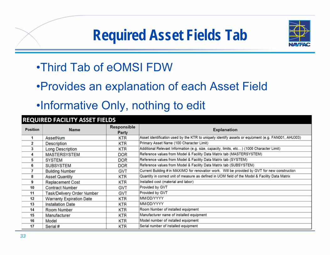
Required Asset Fields Tab
•Third Tab of eOMSI FDW•Provides an explanation of each Asset Field•Informative Only, nothing to edit

34
Sample KTR Facility Data File Tab
•Fourth Tab of eOMSI FDW•Provides KTR with an example•Informative Only, nothing to edit

35
KTR Facility Data File Tab
KTR FACILITY DATA FILEEach facility component or piece of equipment will be a new row. Refer to Model & Facility Data Matrix for guidance on which fields are applicable to specific components & equipment.
Position 1 2 3 4 5 6 7 8 9 10 11 12 13 14 15 16 17
Name AssetNum Description Long Description MASTERSYSTEM SYSTEM SUBSYSTEM Building Number Asset Quantity Replacement
Cost Contract Number
Task/Delivery Order Number
Warranty Expiration Date
Installation Date
Room Number
Manufacturer Model Serial #
Explanation
Asset identification used by the KTR to uniquely identify
assets or equipment
(e.g. FAN001, AHU003)
Primary Asset Name (100
Character Limit)
Additional Relevant
Information (e.g. size, capacity, limits, etc…)
(1000 Character Limit)
Reference values from Model & Facility Data
Matrix tab (MASTERSYSTEM
)
Reference values from Model &
Facility Data Matrix tab (SYSTEM)
Reference values from Model &
Facility Data Matrix tab (SUBSYSTEM)
Current Building # in MAXIMO for renovation work. Will be provided by GVT for new
construction
Quantity in correct unit of
measure as defined in UOM
field of the Model & Facility Data
Matrix
Installed cost (material and labor) from schedule of values, bid
proposal, etc.
Provided by GVT Provided by GVT MM/DD/YYYY MM/DD/YYY
Y
Room Number of installed
equipment
Manufacturer name of installed
equipment
Model number of installed
equipment
Serial number of installed
equipment
• Fifth Tab of eOMSI FDW• KTR completes FDW based on
Mastersystems, Systems & Subsystems selected by DOR
• Final FDW is modified by DPW FMS into a flat file for MAXIMO upload

36
DBB: eOMSI Submittal Process
37
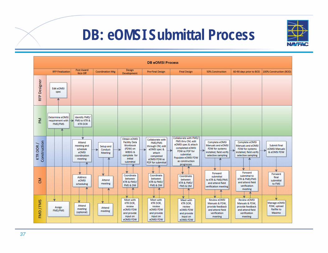
DB: eOMSI Submittal Process
38
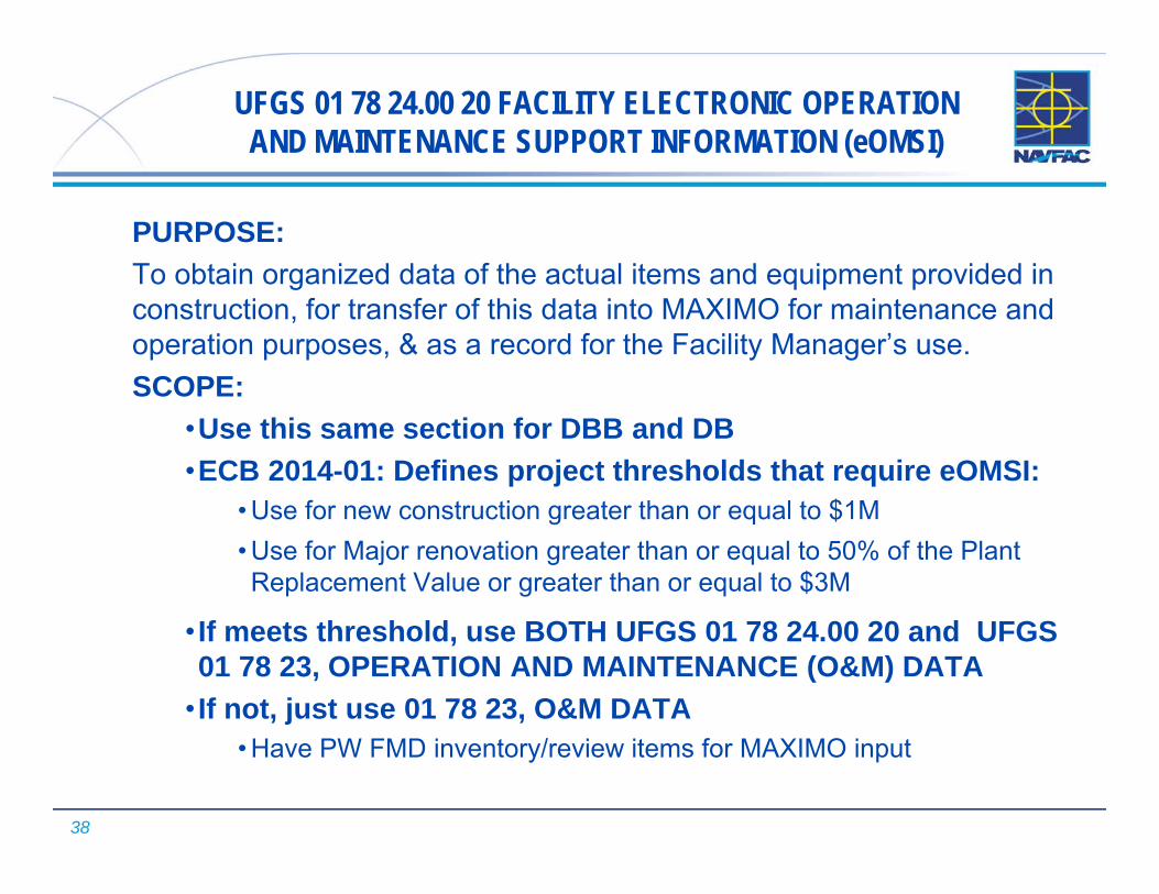
UFGS 01 78 24.00 20 FACILITY ELECTRONIC OPERATION AND MAINTENANCE SUPPORT INFORMATION (eOMSI)
PURPOSE: To obtain organized data of the actual items and equipment provided in construction, for transfer of this data into MAXIMO for maintenance and operation purposes, & as a record for the Facility Manager’s use.SCOPE:
•Use this same section for DBB and DB•ECB 2014-01: Defines project thresholds that require eOMSI:
• Use for new construction greater than or equal to $1M• Use for Major renovation greater than or equal to 50% of the Plant Replacement Value or greater than or equal to $3M
• If meets threshold, use BOTH UFGS 01 78 24.00 20 and UFGS 01 78 23, OPERATION AND MAINTENANCE (O&M) DATA
• If not, just use 01 78 23, O&M DATA• Have PW FMD inventory/review items for MAXIMO input

39
UFGS 01 78 24.00 20 - Organization
PART 1 GENERAL1. References2. Definitions and
Abbreviations3. eOMSI Meeting
Schedules4. Submittal
Scheduling5. Units of Measure6. Submittals
PART 2 PRODUCTS1. eOMSI Files
Format:• eOMSI Manual
Organization• eOMSI Manual
Compact Disk Label
2. eOMSI Manual• Product and
Drawing Information• Facility Information
3. eOMSI Facility Data Workbook (FDW)
PART 3 EXECUTION1. Field
Verification

40
Section Notes to the Designer
Tailoring Options:•DBB •DB •eOMSI Facility Data Workbook (FDW)
•Commissioning Authority
•NAVFAC EURAFSWA
•NAVFAC FE
Section Organization:• eOMSI Manual• eOMSI FDW
When to use the eOMSI Facility Data Workbook (FDW):• Set up for use with
NAVY MAXIMO facilities only right now!
• Marine Corps interested but awaiting their requirements/specifics
• Not required for Army and Air Force facilities
ECB 2014-01 $ LIMITS!
and…..

41
General Section Notes (cont.)
•Contact your NAVFAC PW Facility Management Division (FMD) who will assist CI team to edit Section and FDW!
How To Download eOMSI Facility Data Workbook (FDW)1. Go To: http://www.wbdg.org/ccb/NAVGRAPH/graphtoc.pdf
2. Locate 01 78 24.00 20 in the UFGS Number column.
3. Select the eOMSIFacilityDataWorkbook.zip link in the Graphic Hyperlink column.
4. Save the .ZIP file to your desktop or network share
5. Extract the eOMSI Facility Data Workbook from the .ZIP file to your project folder.

42
1.1 References/1.2 Definitions & Abbreviations
1.1 References:• FC 1-300-09N Navy and Marine Corps Design
Procedures (April 2015)
1.2 Definitions used in Section and FDW:• eOMSI Manual
• eOMSI Facility Data Workbook (FDW)
• Systems
• CADD
• KTR (used in FDW)

43
1.3 eOMSI Meetings
1.3.1 Pre-Construction Meeting (for DBB) or Post-Award Kickoff Meeting (for DB):
•Ensure all parties understand what is required to put together the eOMSI Manuals, and fill in FDW throughout construction
•Ensure parties understand when submittals of the FDW must be provided
•Include eOMSI submittals in the construction schedule
•Describes the meetings required throughout Construction (and Design for DB only)
•Contains tailoring for easy pre-editing of DB and DBB, and for Commissioning Authority and Facility Data Workbook

44
1.3 eOMSI Meetings (Cont.)
1.3.2 eOMSI Manual and FDW Coordination Meeting:•Who to include in this meeting:
•Key Contractor personnel:•eOMSI FDW Preparer•QC Manager
•Commissioning Authority (if applicable)•Government DM •Government CM•NAVFAC PW FMD/FMS on project
•Schedule initial meeting to clarify requirements and resolve issues
•Have more if needed as part of regular QC meetings

45
1.3 eOMSI Meetings (Cont.)
1.3.3 Facility Turnover Meetings:•References NAVFAC Red Zone (NRZ) in UFGS 01 30 00 ADMINISTRATIVE REQUIREMENTS or UFGS 01 31 19.05 20 POST AWARD MEETINGS
•Ensures the eOMSI Manuals and FDW become part of Red-Zone checklist, and are received

46
1.4 Submittal Scheduling
Describes what to provide for the three eOMSI submittals and when:
1.4.1 eOMSI, Progress Submittal:•When construction is 50% complete•Ensures Contractor is putting together the Manuals and completing the FDW as construction progresses
•Ensures components and systems are documented before being covered up/enclosed in walls, foundation
1.4.2 eOMSI, Prefinal Submittal:•eOMSI Manual and FDW should be complete•The size (& length) of the project determines when to submit:
•Smaller projects 60 days prior to BOD (suggested)•Larger projects 90 days prior to BOD
• If it is not complete, send it back!

47
1.4 Submittal Scheduling/1.5 Units of Measure
1.4.3 eOMSI, Final Submittal:•Manuals and FDW must be complete and accurate
•Submit at BOD
1.4.4 Final eOMSI Submittal Translation: (if applicable)
•Only applies to Overseas locations with languages other than English
1.5 Units of Measure:• Imperial or Metric

48
1.6 Submittals
•Standard UFGS Submittals Article•eOMSI Manual and Facility Data Workbook (FDW) Submittals
•Level of completion and what needs to be submitted from paragraph 1.4 SUBMITTAL SCHEDULING
eOMSI, Progress Submittal
eOMSI, Prefinal Submittal
eOMSI, Final Submittal

49
PART 2: PRODUCTS
2.3 eOMSI FACILITY DATA
WORKBOOK (FDW)
2.2 eOMSIMANUALS
2.1 eOMSI FILES FORMAT

50
2.1 eOMSI Files Format
Administrative-type requirements for Manuals and FDW:•Number of copies •CD or DVD•eOMSI Manuals as PDFs •eOMSI FDW in Excel
2.1.1 eOMSI Manual Organization:•Bookmarked by:
•Product and Drawing Information•Organize by CSI MasterFormat numbering System and Titles
•Facility Information
2.1.2 eOMSI Manual CD Label and Disk Holder or Case

51
2.2 eOMSI Manuals
• 2.2.1 Product and Drawing Information
• 2.2.2 Facility Information

52
2.2.1 Product and Drawing Information
2.2.1.1 O&M Data:•From UFGS 01 78 23, OPERATION & MAINTENANCE DATA: Remember to edit these paragraphs for what is in the project!
•Paragraph 1.7 describes the Data Package content, i.e.:• Operating Instructions• Safety Precautions and Hazards• Normal Operations• Emergency Operations• Preventive Maintenance• Submittal Data• Warranty Information
•Moving training requirements from 01 78 24.00 20 to here
Compiled and organized Product Data (i.e. cut sheets), Certifications, Data Packages, and approved Shop Drawings submitted in the technical spec sections

53
2.2.1 Product and Drawing Information (Cont.)
2.2.1.2 Record Drawings:•Copy of PDF of the Record Drawings (if prepared by Contractor)
•For DBB, use paragraph and coordinate with UFGS 01 78 00 if the Contractor is preparing the Record Drawings;
•For DBB, delete this paragraph if A/E doing Record Drawings by PCAS
•Always use for DB•Record Drawing preparation IAW FC 1-300-09N & UFGS 01 78 00
2.2.1.3 Utility Record Drawings:•Using Record Source Drawings, show and document details of actual installation of utility systems; annotate and highlight the eOMSI information in PDF Format for the manual
•Utility Schematic Diagrams•Enlarged Connection and Cutoff Plans

54
2.2.2 Facility Information
Drawing Schedules with Manufacturer’s Data
2.2.2.1 General Facility and System Description• Function of the facility• Edit systems
2.2.2.2 Basis of Design• Use for DB Only• Provide a copy of the final Basis of Design
2.2.2.3 Floor Plans
2.2.2.4 Floor Coverings, Wall Surfaces, & Ceiling Surfaces
Remember to edit these paragraphs for what is in the project!

55
2.2.2 Facility Information (Cont.)2.2.2.5 Windows
2.2.2.6 Roofing
2.2.2.7 HVAC Filters
2.2.2.8 Plumbing Fixtures
2.2.2.9 Lighting Fixtures
2.2.2.10 Equipment Listing• Major equipment list
2.2.2.11 System Flow Diagrams• Normal Operations
2.2.2.12 Valve list
2.2.2.13 Riser Diagrams

56
2.3 eOMSI Facility Data Workbook (FDW)•NOTES:
•Contact FMD/FMS for guidance and assistance in editing FDW and identifying the Mastersystems, Systems, and Subsystems!
•For DBB, preliminarily edit FDW and attach to this section (electronically in PDF package)
•For DB, DOR edits the section, & coordinate with NAVFAC PW FMD/FMS
•Brackets and tailoring in paragraphs for DBB and DB
•Description of Tabs:• Instructions Tab•Model & Facility Data Matrix Tab•Required Asset Fields Tab•KTR Sample Facility Data File Tab•KTR Facility Data File Tab

57
3.1 Field Verification
•Perform at 50% construction completion to ensure accuracy and capture items that will be covered up by finishes, etc.
•Perform no less than 60 days prior to BOD to ensure all items captured and accurate
•Sample data by choosing 5 Mastersystems and 5 items under each of them (Who chooses items for verification?)
•Modify and Choose Project Systems to Sample (Conveying, Plumbing, HVAC, Fire Protection, & Electrical)
•Must be 100% accurate, or need to redo!
Verify data in the Workbook to what’s installed!

58
Related Criteria Revisions Status
•UFGS 01 78 23, OPERATION AND MAINTENANCE DATA•Currently in Final Tri-Service review •Target AUG 2015 Release •Moved training requirements from 01 78 24.00 20 to here•Referenced from 01 78 24.00 20 for Operation and Maintenance Data•Contains alternative paragraph for O&M Manuals if 01 78 24.00 20 is not used
•UFGS 01 78 00 CLOSEOUT SUBMITTALS•Under full revision by USACE•Major revision to As-Built, Record Drawings and Record Model with reference to FC 1-300-09N
•Change published in July 2015 release while revision continues -defined Record and As-Built Drawings and reference FC 1-300-09N

59
Related Criteria Revisions Status
•UFGS 01 30 00 ADMINISTRATIVE REQUIREMENTS•Updated Availability of Source Files for Record Drawings•Under Revision with targeted August 2015 Release
•DBB SAES: COMPLETED•Updated to require FDW for DBB AE Projects
•FC 1-300-09N DESIGN PROCEDURES•Level of completion of Facility Data Workbook throughout Design Phases
•Added BIM Modeling requirements•Change 1 published April 2015•Change 2 targeted for FY 15 to clarify PxP submittal in phases
•BMS: CI DB and DBB processes•Data Storage Requirements

60
BIM’s Impact on IHD
Design Submittals remain unchanged from DOR:Refer to FC 1-300-09N Design Procedures
Preliminary Design (CH 12-4.5.3)Final Design (CH 12-4.5.4)
BIM Modeling not applicable for IHD

61
BIM Modeling Requirements
FC 1-300-09N Update: Added Chapter 12-5 Building Information Management/Modeling (BIM) Requirements
•BIM applicability, definitions, procedures & submittals (Section 12-5)
•eOMSI FDW applicability, definition & submittals (Section 12-3.2)
•Instructions to DOR and KTR on how BIM models are developed

62
BIM Modeling Requirements (Cont’d)
Applicability:•ECB 201-01: Applies to projects at Navy Installations, Joint Bases, Department of Defense (DoD) Agencies, or Field Activities where NAVFAC PW is the maintenance provider that meet the following: $1M New Construction; or 50% PRV Major Renovation
Definitions:•Project Execution Plan (PxP)•3D Parametric Modeling Application
Parametric = ParameterData driven

63
BIM Modeling Requirements (Cont’d)
Definitions:•Model - Entire facility/building•Model Element - Individual building components: Walls, Doors, Windows, Pumps, Air Handlers, etc.
•Element Data:•Physical Size - Length, Width, & Height•Material Definitions - Wood, Metal, Plastic, Color•Required Facility Asset Fields - up to 17 in eOMSI FDW
64
BIM Modeling Requirements (Cont’d)
Definitions:•Design Model – 3D parametric model by the DOR
•Record Model – KTR modifies Design Model as facility is constructed & equipment installed
•See Figure 12-4 Drawing and Model Progression
•eOMSI FDW - Excel workbook containing Facility Mastersystems, Systems & Subsystems for PW MAXIMO upload

65
BIM Modeling Requirements (Cont’d)
Procedures:
•Model File Naming Conventions
•Design Model Naming Convention (DOR)
•Record Model Naming Convention (KTR)

66 10/15/2015
BIM Modeling Requirements (Cont’d)
Procedures:•Minimum Modeling Requirements
•Use of Parametric Modeling software is required•Model and Facility Data Matrix
•Created and Refined throughout Design phase•DO NOT break up the spreadsheet!!!
•One Model for Each Discipline•Each discipline model (ARCH, STRUCT, MEP) linked & documented in PxP
•Data driven schedules•Finish, Equipment, Lighting, Plumbing & Door Schedules

67
BIM Modeling Requirements (Cont’d)
Submittals:•Visual Review Report
•DOR document that compares FDW to Model Elements
•Ensures all items identified in Model and Facility Data Matrix tab are present in Model
•Identifies Model Elements that are not selected in the FDW
•Design Clash Detection•Confirms DOR conducted clash detection & found no clashing Model Elements
•BIM Submittals are in ADDITION to the submittals we receive for Non-BIM projects

68
QUESTIONS???