Embed Size (px)
Citation preview
Bridgelux® Vero® SE 29 ArrayProduct Data Sheet DS123
BXRC-27x10K0 | 30x10K0 | 35x10K0 | 40x10K0 | 50x10K1 | 57x10K1 | 65x10K1
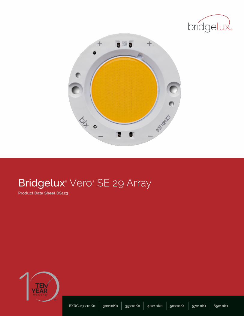
Introduction
Vero® SE Series represents a state of the art COB solution with revolutionary advancements in LED integration
technology. Vero SE’s innovative light source system integrates Bridgelux’s seventh generation COB technology with
poke-in connectivity that enables solder free installation. Vero SE LED light sources streamline assembly processes,
lower manufacturing cost, simplify luminaire design, improve light quality and increase design flexibility.
Vero SE poke-in connectivity simplifies manufacturing and assembly processes by eliminating the need to solder.
Secondary connector and holder components are not required, allowing for rapid integration of arrays into fixtures and
an efficient field replaceable solution.
Vero SE is available in four different light emitting surface (LES) configurations and has been engineered to reliably
operate over a broad current range, enabling new degrees of flexibility in luminaire design optimization. Vero SE arrays
deliver increased lumen density for improved beam control and precision lighting with 2 and 3 SDCM color control
standards for clean and consistent uniform lighting.
Ve
ro S
EFeatures
• Poke-in connectivity
• Efficacy of 155 lm/W typical
• Vero SE 29 lumen output performance ranges from 5,368 to 37,173 lumens
• Broad range of CCT options from 2700K to 6500K
• CRI options: minimum 70, 80, and 90
• Color control: 2 and 3 SDCM for 2700K-4000K CCT
• Reliable operation at up to 2X nominal drive current
• Radial die pattern and improved lumen density
• Top side part number markings
• No exposed solder pads or electrical connections
Benefits
• Poke-in connectivity enables solderless, connector
free installation
• Broad application coverage for interior and exterior lighting
• Flexibility for application driven lighting design requirements
• High quality, true color reproduction
• Uniform consistent white light
• Flexibility in design optimization
• Enhanced ease of use and assembly
• Ability to configure multiple arrays in series and parallel reduces customer driver cost
• Improved inventory management and quality control
Contents
1
Product Feature Map 2
Product Nomenclature 2
Product Selection Guide 3
Performance at Commonly Used Drive Currents 7
Electrical Characteristics 13
Eye Safety 14
Absolute Maximum Ratings 15
Performance Curves 16
Typical Radiation Pattern 21
Typical Color Spectrum 22
Mechanical Dimensions 23
Color Binning Information 24
Packaging and Labeling 25
Design Resources 27
Precautions 27
Disclaimers 27
About Bridgelux 28
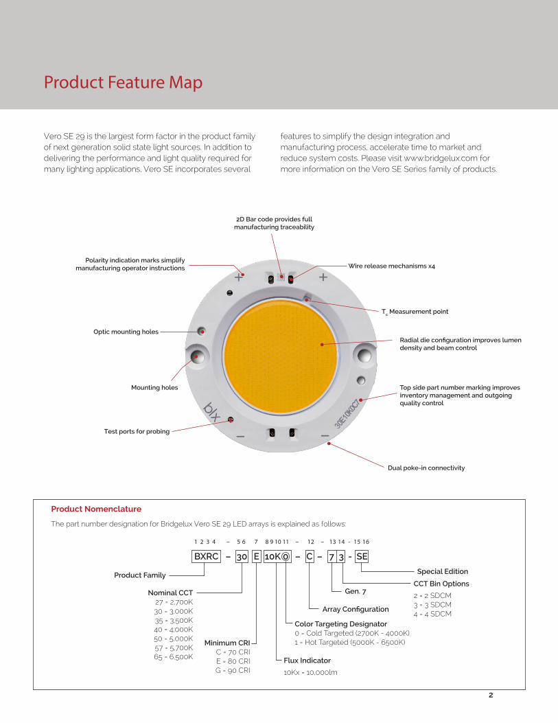
Product Feature Map
Vero SE 29 is the largest form factor in the product family of next generation solid state light sources. In addition to delivering the performance and light quality required for many lighting applications, Vero SE incorporates several
Product Nomenclature
The part number designation for Bridgelux Vero SE 29 LED arrays is explained as follows:
features to simplify the design integration and manufacturing process, accelerate time to market and reduce system costs. Please visit www.bridgelux.com for more information on the Vero SE Series family of products.
2
1 2 3 4 – 5 6 7 8 9 10 11 – 12 – 13 14 - 15 16
Product FamilyCCT Bin Options
2 = 2 SDCM3 = 3 SDCM4 = 4 SDCM
Flux Indicator
10Kx = 10,000lm
Minimum CRIC = 70 CRIE = 80 CRIG = 90 CRI
Array Configuration
Nominal CCT27 = 2,700K30 = 3,000K35 = 3,500K40 = 4,000K50 = 5,000K57 = 5,700K65 = 6,500K
BXRC – 30 E 10K 0 – C – 7 3 - SE
Mounting holes
Polarity indication marks simplify manufacturing operator instructions
2D Bar code provides full manufacturing traceability
Dual poke-in connectivity
Wire release mechanisms x4
Tc Measurement point
Radial die configuration improves lumen density and beam control
Top side part number marking improves inventory management and outgoing quality control
Color Targeting Designator0 = Cold Targeted (2700K - 4000K)1 = Hot Targeted (5000K - 6500K)
Gen. 7
Special Edition
Test ports for probing
Optic mounting holes
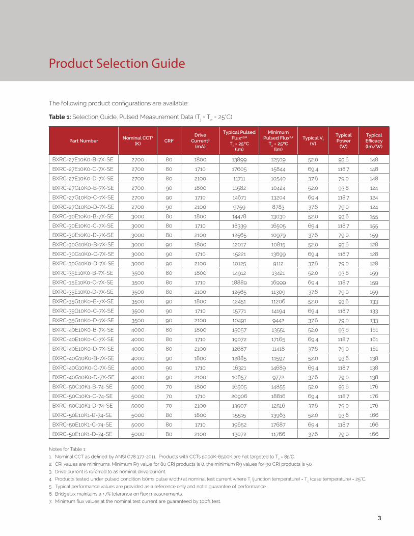
Product Selection Guide
The following product configurations are available:
Table 1: Selection Guide, Pulsed Measurement Data (Tj = Tc = 25°C)
Notes for Table 1:
1. Nominal CCT as defined by ANSI C78.377-2011. Products with CCTs 5000K-6500K are hot targeted to Tc = 85°C.
2. CRI values are minimums. Minimum R9 value for 80 CRI products is 0, the minimum R9 values for 90 CRI products is 50.
3. Drive current is referred to as nominal drive current.
4. Products tested under pulsed condition (10ms pulse width) at nominal test current where Tj (junction temperature) = Tc (case temperature) = 25°C.
5. Typical performance values are provided as a reference only and not a guarantee of performance.
6. Bridgelux maintains a ±7% tolerance on flux measurements.
7. Minimum flux values at the nominal test current are guaranteed by 100% test.
Part NumberNominal CCT1
(K)CRI2
Drive Current3
(mA)
Typical Pulsed Flux4,5,6
Tc = 25ºC(lm)
Minimum Pulsed Flux6,7
Tc = 25ºC(lm)
Typical Vf (V)
Typical Power
(W)
Typical Efficacy (lm/W)
BXRC-27E10K0-B-7X-SE 2700 80 1800 13899 12509 52.0 93.6 148
BXRC-27E10K0-C-7X-SE 2700 80 1710 17605 15844 69.4 118.7 148
BXRC-27E10K0-D-7X-SE 2700 80 2100 11711 10540 37.6 79.0 148
BXRC-27G10K0-B-7X-SE 2700 90 1800 11582 10424 52.0 93.6 124
BXRC-27G10K0-C-7X-SE 2700 90 1710 14671 13204 69.4 118.7 124
BXRC-27G10K0-D-7X-SE 2700 90 2100 9759 8783 37.6 79.0 124
BXRC-30E10K0-B-7X-SE 3000 80 1800 14478 13030 52.0 93.6 155
BXRC-30E10K0-C-7X-SE 3000 80 1710 18339 16505 69.4 118.7 155
BXRC-30E10K0-D-7X-SE 3000 80 2100 12565 10979 37.6 79.0 159
BXRC-30G10K0-B-7X-SE 3000 90 1800 12017 10815 52.0 93.6 128
BXRC-30G10K0-C-7X-SE 3000 90 1710 15221 13699 69.4 118.7 128
BXRC-30G10K0-D-7X-SE 3000 90 2100 10125 9112 37.6 79.0 128
BXRC-35E10K0-B-7X-SE 3500 80 1800 14912 13421 52.0 93.6 159
BXRC-35E10K0-C-7X-SE 3500 80 1710 18889 16999 69.4 118.7 159
BXRC-35E10K0-D-7X-SE 3500 80 2100 12565 11309 37.6 79.0 159
BXRC-35G10K0-B-7X-SE 3500 90 1800 12451 11206 52.0 93.6 133
BXRC-35G10K0-C-7X-SE 3500 90 1710 15771 14194 69.4 118.7 133
BXRC-35G10K0-D-7X-SE 3500 90 2100 10491 9442 37.6 79.0 133
BXRC-40E10K0-B-7X-SE 4000 80 1800 15057 13551 52.0 93.6 161
BXRC-40E10K0-C-7X-SE 4000 80 1710 19072 17165 69.4 118.7 161
BXRC-40E10K0-D-7X-SE 4000 80 2100 12687 11418 37.6 79.0 161
BXRC-40G10K0-B-7X-SE 4000 90 1800 12885 11597 52.0 93.6 138
BXRC-40G10K0-C-7X-SE 4000 90 1710 16321 14689 69.4 118.7 138
BXRC-40G10K0-D-7X-SE 4000 90 2100 10857 9772 37.6 79.0 138
BXRC-50C10K1-B-74-SE 5000 70 1800 16505 14855 52.0 93.6 176
BXRC-50C10K1-C-74-SE 5000 70 1710 20906 18816 69.4 118.7 176
BXRC-50C10K1-D-74-SE 5000 70 2100 13907 12516 37.6 79.0 176
BXRC-50E10K1-B-74-SE 5000 80 1800 15515 13963 52.0 93.6 166
BXRC-50E10K1-C-74-SE 5000 80 1710 19652 17687 69.4 118.7 166
BXRC-50E10K1-D-74-SE 5000 80 2100 13072 11766 37.6 79.0 166
3
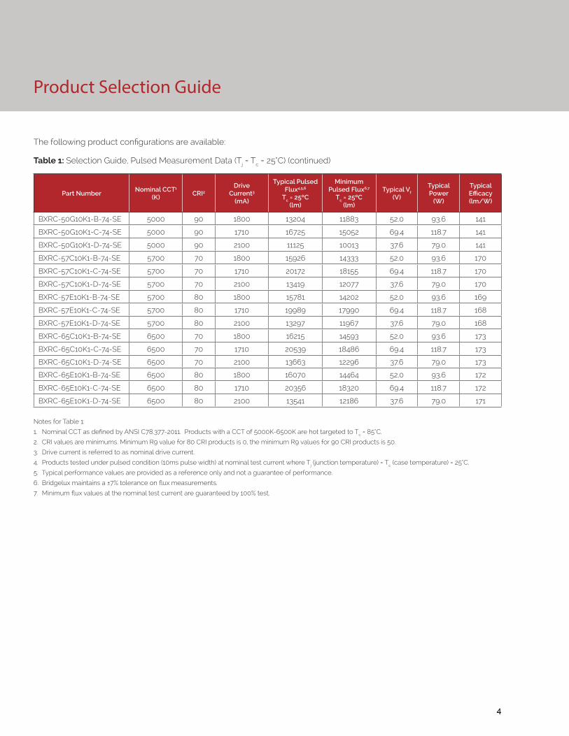
Product Selection Guide
The following product configurations are available:
Table 1: Selection Guide, Pulsed Measurement Data (Tj = Tc = 25°C) (continued)
Notes for Table 1:
1. Nominal CCT as defined by ANSI C78.377-2011. Products with a CCT of 5000K-6500K are hot targeted to Tc = 85°C.
2. CRI values are minimums. Minimum R9 value for 80 CRI products is 0, the minimum R9 values for 90 CRI products is 50.
3. Drive current is referred to as nominal drive current.
4. Products tested under pulsed condition (10ms pulse width) at nominal test current where Tj (junction temperature) = Tc (case temperature) = 25°C.
5. Typical performance values are provided as a reference only and not a guarantee of performance.
6. Bridgelux maintains a ±7% tolerance on flux measurements.
7. Minimum flux values at the nominal test current are guaranteed by 100% test.
Part NumberNominal CCT1
(K)CRI2
Drive Current3
(mA)
Typical Pulsed Flux4,5,6
Tc = 25ºC(lm)
Minimum Pulsed Flux6,7
Tc = 25ºC(lm)
Typical Vf (V)
Typical Power
(W)
Typical Efficacy (lm/W)
BXRC-50G10K1-B-74-SE 5000 90 1800 13204 11883 52.0 93.6 141
BXRC-50G10K1-C-74-SE 5000 90 1710 16725 15052 69.4 118.7 141
BXRC-50G10K1-D-74-SE 5000 90 2100 11125 10013 37.6 79.0 141
BXRC-57C10K1-B-74-SE 5700 70 1800 15926 14333 52.0 93.6 170
BXRC-57C10K1-C-74-SE 5700 70 1710 20172 18155 69.4 118.7 170
BXRC-57C10K1-D-74-SE 5700 70 2100 13419 12077 37.6 79.0 170
BXRC-57E10K1-B-74-SE 5700 80 1800 15781 14202 52.0 93.6 169
BXRC-57E10K1-C-74-SE 5700 80 1710 19989 17990 69.4 118.7 168
BXRC-57E10K1-D-74-SE 5700 80 2100 13297 11967 37.6 79.0 168
BXRC-65C10K1-B-74-SE 6500 70 1800 16215 14593 52.0 93.6 173
BXRC-65C10K1-C-74-SE 6500 70 1710 20539 18486 69.4 118.7 173
BXRC-65C10K1-D-74-SE 6500 70 2100 13663 12296 37.6 79.0 173
BXRC-65E10K1-B-74-SE 6500 80 1800 16070 14464 52.0 93.6 172
BXRC-65E10K1-C-74-SE 6500 80 1710 20356 18320 69.4 118.7 172
BXRC-65E10K1-D-74-SE 6500 80 2100 13541 12186 37.6 79.0 171
4
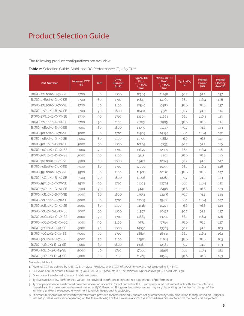
Product Selection Guide
The following product configurations are available:
Table 2: Selection Guide, Stabilized DC Performance (Tc = 85°C) 4,5
Part NumberNominal CCT1
(K)CRI2
Drive Current3
(mA)
Typical DC Flux
Tc = 85ºC(lm)
Minimum DC Flux6
Tc = 85ºC(lm)
Typical Vf (V)
Typical Power
(W)
Typical Efficacy (lm/W)
BXRC-27E10K0-B-7X-SE 2700 80 1800 12509 11258 50.7 91.2 137
BXRC-27E10K0-C-7X-SE 2700 80 1710 15845 14260 68.1 116.4 136
BXRC-27E10K0-D-7X-SE 2700 80 2100 10540 9486 36.6 76.8 137
BXRC-27G10K0-B-7X-SE 2700 90 1800 10424 9381 50.7 91.2 114
BXRC-27G10K0-C-7X-SE 2700 90 1710 13204 11884 68.1 116.4 113
BXRC-27G10K0-D-7X-SE 2700 90 2100 8783 7905 36.6 76.8 114
BXRC-30E10K0-B-7X-SE 3000 80 1800 13030 11727 50.7 91.2 143
BXRC-30E10K0-C-7X-SE 3000 80 1710 16505 14854 68.1 116.4 142
BXRC-30E10K0-D-7X-SE 3000 80 2100 11309 9882 36.6 76.8 147
BXRC-30G10K0-B-7X-SE 3000 90 1800 10815 9733 50.7 91.2 119
BXRC-30G10K0-C-7X-SE 3000 90 1710 13699 12329 68.1 116.4 118
BXRC-30G10K0-D-7X-SE 3000 90 2100 9113 8201 36.6 76.8 119
BXRC-35E10K0-B-7X-SE 3500 80 1800 13421 12079 50.7 91.2 147
BXRC-35E10K0-C-7X-SE 3500 80 1710 17000 15299 68.1 116.4 146
BXRC-35E10K0-D-7X-SE 3500 80 2100 11308 10178 36.6 76.8 147
BXRC-35G10K0-B-7X-SE 3500 90 1800 11206 10085 50.7 91.2 123
BXRC-35G10K0-C-7X-SE 3500 90 1710 14194 12775 68.1 116.4 122
BXRC-35G10K0-D-7X-SE 3500 90 2100 9442 8498 36.6 76.8 123
BXRC-40E10K0-B-7X-SE 4000 80 1800 13551 12196 50.7 91.2 149
BXRC-40E10K0-C-7X-SE 4000 80 1710 17165 15448 68.1 116.4 147
BXRC-40E10K0-D-7X-SE 4000 80 2100 11418 10277 36.6 76.8 149
BXRC-40G10K0-B-7X-SE 4000 90 1800 11597 10437 50.7 91.2 127
BXRC-40G10K0-C-7X-SE 4000 90 1710 14689 13220 68.1 116.4 126
BXRC-40G10K0-D-7X-SE 4000 90 2100 9771 8794 36.6 76.8 127
BXRC-50C10K1-B-74-SE 5000 70 1800 14854 13369 50.7 91.2 163
BXRC-50C10K1-C-74-SE 5000 70 1710 18815 16934 68.1 116.4 162
BXRC-50C10K1-D-74-SE 5000 70 2100 12516 11264 36.6 76.8 163
BXRC-50E10K1-B-74-SE 5000 80 1800 13963 12567 50.7 91.2 153
BXRC-50E10K1-C-74-SE 5000 80 1710 17686 15918 68.1 116.4 152
BXRC-50E10K1-D-74-SE 5000 80 2100 11765 10589 36.6 76.8 153
5
Notes for Tables 2:
1. Nominal CCT as defined by ANSI C78.377-2011. Products with a CCT of 5000K-6500K are hot targeted to Tc = 85°C.
2. CRI values are minimums. Minimum R9 value for 80 CRI products is 0, the minimum R9 values for 90 CRI products is 50.
3. Drive current is referred to as nominal drive current.
4. Typical stabilized DC performance values are provided as reference only and not a guarantee of performance.
5. Typical performance is estimated based on operation under DC (direct current) with LED array mounted onto a heat sink with thermal interface material and the case temperature maintained at 85°C. Based on Bridgelux test setup, values may vary depending on the thermal design of the luminaire and/or the exposed environment to which the product is subjected.
6. Minimum flux values at elevated temperatures are provided for reference only and are not guaranteed by 100% production testing. Based on Bridgelux test setup, values may vary depending on the thermal design of the luminaire and/or the exposed environment to which the product is subjected.
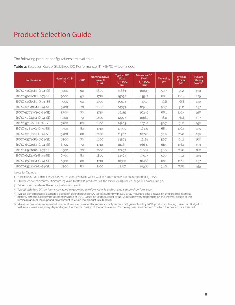
Product Selection Guide
The following product configurations are available:
Table 2: Selection Guide, Stabilized DC Performance (Tc = 85°C) 4,5 (continued)
Part NumberNominal CCT1
(K)CRI2
Nominal Drive Current3
(mA)
Typical DC Flux
Tc = 85ºC(lm)
Minimum DC Flux6
Tc = 85ºC(lm)
Typical Vf (V)
Typical Power
(W)
Typical Efficacy (lm/W)
BXRC-50G10K1-B-74-SE 5000 90 1800 11883 10695 50.7 91.2 130
BXRC-50G10K1-C-74-SE 5000 90 1710 15052 13547 68.1 116.4 129
BXRC-50G10K1-D-74-SE 5000 90 2100 10013 9012 36.6 76.8 130
BXRC-57C10K1-B-74-SE 5700 70 1800 14333 12900 50.7 91.2 157
BXRC-57C10K1-C-74-SE 5700 70 1710 18155 16340 68.1 116.4 156
BXRC-57C10K1-D-74-SE 5700 70 2100 12077 10869 36.6 76.8 157
BXRC-57E10K1-B-74-SE 5700 80 1800 14203 12782 50.7 91.2 156
BXRC-57E10K1-C-74-SE 5700 80 1710 17990 16191 68.1 116.4 155
BXRC-57E10K1-D-74-SE 5700 80 2100 11967 10770 36.6 76.8 156
BXRC-65C10K1-B-74-SE 6500 70 1800 14594 13134 50.7 91.2 160
BXRC-65C10K1-C-74-SE 6500 70 1710 18485 16637 68.1 116.4 159
BXRC-65C10K1-D-74-SE 6500 70 2100 12297 11067 36.6 76.8 160
BXRC-65E10K1-B-74-SE 6500 80 1800 14463 13017 50.7 91.2 159
BXRC-65E10K1-C-74-SE 6500 80 1710 18320 16488 68.1 116.4 157
BXRC-65E10K1-D-74-SE 6500 80 2100 12187 10968 36.6 76.8 159
6
Notes for Tables 2:
1. Nominal CCT as defined by ANSI C78.377-2011. Products with a CCT of 5000K-6500K are hot targeted to Tc = 85°C.
2. CRI values are minimums. Minimum R9 value for 80 CRI products is 0, the minimum R9 values for 90 CRI products is 50.
3. Drive current is referred to as nominal drive current.
4. Typical stabilized DC performance values are provided as reference only and not a guarantee of performance.
5. Typical performance is estimated based on operation under DC (direct current) with LED array mounted onto a heat sink with thermal interface material and the case temperature maintained at 85°C. Based on Bridgelux test setup, values may vary depending on the thermal design of the luminaire and/or the exposed environment to which the product is subjected.
6. Minimum flux values at elevated temperatures are provided for reference only and are not guaranteed by 100% production testing. Based on Bridgelux test setup, values may vary depending on the thermal design of the luminaire and/or the exposed environment to which the product is subjected.
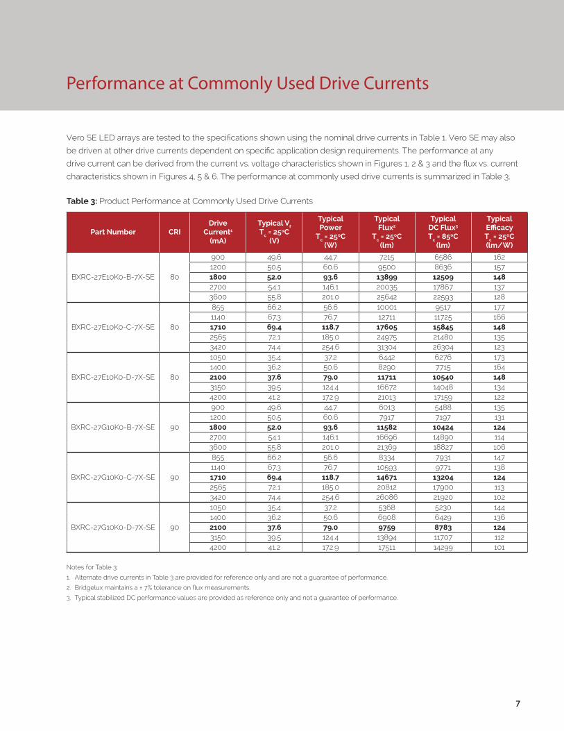
Performance at Commonly Used Drive Currents
Vero SE LED arrays are tested to the specifications shown using the nominal drive currents in Table 1. Vero SE may also
be driven at other drive currents dependent on specific application design requirements. The performance at any
drive current can be derived from the current vs. voltage characteristics shown in Figures 1, 2 & 3 and the flux vs. current
characteristics shown in Figures 4, 5 & 6. The performance at commonly used drive currents is summarized in Table 3.
7
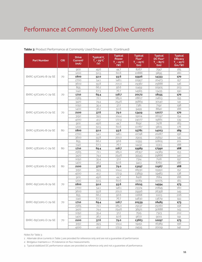
Table 3: Product Performance at Commonly Used Drive Currents
Part Number CRIDrive
Current1
(mA)
Typical Vf Tc = 25ºC
(V)
Typical Power
Tc = 25ºC(W)
Typical Flux2
Tc = 25ºC(lm)
Typical DC Flux3 Tc = 85ºC
(lm)
Typical Efficacy Tc = 25ºC(lm/W)
BXRC-27E10K0-B-7X-SE 80
900 49.6 44.7 7215 6586 1621200 50.5 60.6 9500 8636 1571800 52.0 93.6 13899 12509 1482700 54.1 146.1 20035 17867 1373600 55.8 201.0 25642 22593 128
BXRC-27E10K0-C-7X-SE 80
855 66.2 56.6 10001 9517 1771140 67.3 76.7 12711 11725 1661710 69.4 118.7 17605 15845 1482565 72.1 185.0 24975 21480 1353420 74.4 254.6 31304 26304 123
BXRC-27E10K0-D-7X-SE 80
1050 35.4 37.2 6442 6276 1731400 36.2 50.6 8290 7715 1642100 37.6 79.0 11711 10540 1483150 39.5 124.4 16672 14048 1344200 41.2 172.9 21013 17159 122
BXRC-27G10K0-B-7X-SE 90
900 49.6 44.7 6013 5488 1351200 50.5 60.6 7917 7197 1311800 52.0 93.6 11582 10424 1242700 54.1 146.1 16696 14890 1143600 55.8 201.0 21369 18827 106
BXRC-27G10K0-C-7X-SE 90
855 66.2 56.6 8334 7931 1471140 67.3 76.7 10593 9771 1381710 69.4 118.7 14671 13204 1242565 72.1 185.0 20812 17900 1133420 74.4 254.6 26086 21920 102
BXRC-27G10K0-D-7X-SE 90
1050 35.4 37.2 5368 5230 1441400 36.2 50.6 6908 6429 1362100 37.6 79.0 9759 8783 1243150 39.5 124.4 13894 11707 1124200 41.2 172.9 17511 14299 101
Notes for Table 3:
1. Alternate drive currents in Table 3 are provided for reference only and are not a guarantee of performance.
2. Bridgelux maintains a ± 7% tolerance on flux measurements.
3. Typical stabilized DC performance values are provided as reference only and not a guarantee of performance.
8
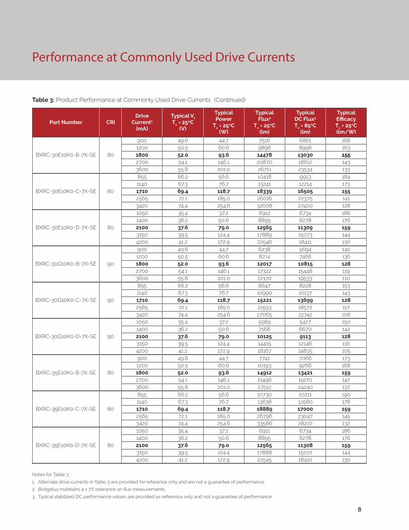
Performance at Commonly Used Drive Currents
Notes for Table 3:
1. Alternate drive currents in Table 3 are provided for reference only and are not a guarantee of performance.
2. Bridgelux maintains a ± 7% tolerance on flux measurements.
3. Typical stabilized DC performance values are provided as reference only and not a guarantee of performance.
Table 3: Product Performance at Commonly Used Drive Currents (Continued)
Part Number CRIDrive
Current1
(mA)
Typical Vf Tc = 25ºC
(V)
Typical Power
Tc = 25ºC(W)
Typical Flux2
Tc = 25ºC(lm)
Typical DC Flux3 Tc = 85ºC
(lm)
Typical Efficacy Tc = 25ºC(lm/W)
BXRC-30E10K0-B-7X-SE 80
900 49.6 44.7 7516 6861 1681200 50.5 60.6 9896 8996 1631800 52.0 93.6 14478 13030 1552700 54.1 146.1 20870 18612 1433600 55.8 201.0 26711 23534 133
BXRC-30E10K0-C-7X-SE 80
855 66.2 56.6 10418 9913 1841140 67.3 76.7 13241 12214 1731710 69.4 118.7 18339 16505 1552565 72.1 185.0 26016 22375 1413420 74.4 254.6 32608 27400 128
BXRC-30E10K0-D-7X-SE 80
1050 35.4 37.2 6912 6734 1861400 36.2 50.6 8895 8278 1762100 37.6 79.0 12565 11309 1593150 39.5 124.4 17889 15073 1444200 41.2 172.9 22546 18411 130
BXRC-30G10K0-B-7X-SE 90
900 49.6 44.7 6238 5694 1401200 50.5 60.6 8214 7466 1361800 52.0 93.6 12017 10815 1282700 54.1 146.1 17322 15448 1193600 55.8 201.0 22170 19533 110
BXRC-30G10K0-C-7X-SE 90
855 66.2 56.6 8647 8228 1531140 67.3 76.7 10990 10137 1431710 69.4 118.7 15221 13699 1282565 72.1 185.0 21593 18572 1173420 74.4 254.6 27065 22742 106
BXRC-30G10K0-D-7X-SE 90
1050 35.4 37.2 5569 5427 1501400 36.2 50.6 7168 6670 1422100 37.6 79.0 10125 9113 1283150 39.5 124.4 14415 12146 1164200 41.2 172.9 18167 14835 105
BXRC-35E10K0-B-7X-SE 80
900 49.6 44.7 7741 7066 1731200 50.5 60.6 10193 9266 1681800 52.0 93.6 14912 13421 1592700 54.1 146.1 21496 19170 1473600 55.8 201.0 27512 24240 137
BXRC-35E10K0-C-7X-SE 80
855 66.2 56.6 10730 10211 1901140 67.3 76.7 13638 12580 1781710 69.4 118.7 18889 17000 1592565 72.1 185.0 26796 23047 1453420 74.4 254.6 33586 28222 132
BXRC-35E10K0-D-7X-SE 80
1050 35.4 37.2 6911 6734 1861400 36.2 50.6 8895 8278 1762100 37.6 79.0 12565 11308 1593150 39.5 124.4 17888 15072 1444200 41.2 172.9 22545 18410 130
9
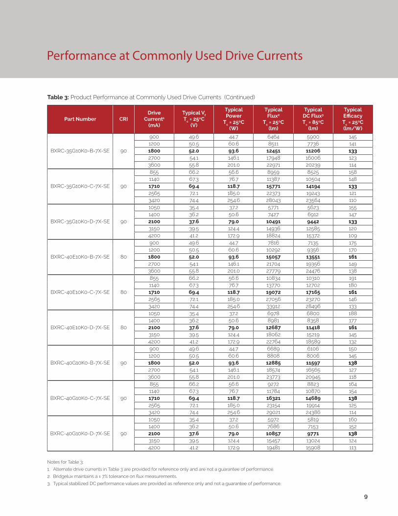
Notes for Table 3:
1. Alternate drive currents in Table 3 are provided for reference only and are not a guarantee of performance.
2. Bridgelux maintains a ± 7% tolerance on flux measurements.
3. Typical stabilized DC performance values are provided as reference only and not a guarantee of performance.
Table 3: Product Performance at Commonly Used Drive Currents (Continued)
Part Number CRIDrive
Current1
(mA)
Typical Vf Tc = 25ºC
(V)
Typical Power
Tc = 25ºC(W)
Typical Flux2
Tc = 25ºC(lm)
Typical DC Flux3 Tc = 85ºC
(lm)
Typical Efficacy Tc = 25ºC(lm/W)
BXRC-35G10K0-B-7X-SE 90
900 49.6 44.7 6464 5900 1451200 50.5 60.6 8511 7736 1411800 52.0 93.6 12451 11206 1332700 54.1 146.1 17948 16006 1233600 55.8 201.0 22971 20239 114
BXRC-35G10K0-C-7X-SE 90
855 66.2 56.6 8959 8525 1581140 67.3 76.7 11387 10504 1481710 69.4 118.7 15771 14194 1332565 72.1 185.0 22373 19243 1213420 74.4 254.6 28043 23564 110
BXRC-35G10K0-D-7X-SE 90
1050 35.4 37.2 5771 5623 1551400 36.2 50.6 7427 6912 1472100 37.6 79.0 10491 9442 1333150 39.5 124.4 14936 12585 1204200 41.2 172.9 18824 15372 109
BXRC-40E10K0-B-7X-SE 80
900 49.6 44.7 7816 7135 1751200 50.5 60.6 10292 9356 1701800 52.0 93.6 15057 13551 1612700 54.1 146.1 21704 19356 1493600 55.8 201.0 27779 24476 138
BXRC-40E10K0-C-7X-SE 80
855 66.2 56.6 10834 10310 1911140 67.3 76.7 13770 12702 1801710 69.4 118.7 19072 17165 1612565 72.1 185.0 27056 23270 1463420 74.4 254.6 33912 28496 133
BXRC-40E10K0-D-7X-SE 80
1050 35.4 37.2 6978 6800 1881400 36.2 50.6 8981 8358 1772100 37.6 79.0 12687 11418 1613150 39.5 124.4 18062 15219 1454200 41.2 172.9 22764 18589 132
BXRC-40G10K0-B-7X-SE 90
900 49.6 44.7 6689 6106 1501200 50.5 60.6 8808 8006 1451800 52.0 93.6 12885 11597 1382700 54.1 146.1 18574 16565 1273600 55.8 201.0 23773 20945 118
BXRC-40G10K0-C-7X-SE 90
855 66.2 56.6 9272 8823 1641140 67.3 76.7 11784 10870 1541710 69.4 118.7 16321 14689 1382565 72.1 185.0 23154 19914 1253420 74.4 254.6 29021 24386 114
BXRC-40G10K0-D-7X-SE 90
1050 35.4 37.2 5972 5819 1601400 36.2 50.6 7686 7153 1522100 37.6 79.0 10857 9771 1383150 39.5 124.4 15457 13024 1244200 41.2 172.9 19481 15908 113
Performance at Commonly Used Drive Currents

10
Performance at Commonly Used Drive Currents
Notes for Table 3:
1. Alternate drive currents in Table 3 are provided for reference only and are not a guarantee of performance.
2. Bridgelux maintains a ± 7% tolerance on flux measurements.
3. Typical stabilized DC performance values are provided as reference only and not a guarantee of performance.
Table 3: Product Performance at Commonly Used Drive Currents (Continued)
Part Number CRIDrive
Current1
(mA)
Typical Vf Tc = 25ºC
(V)
Typical Power
Tc = 25ºC(W)
Typical Flux2
Tc = 25ºC(lm)
Typical DC Flux3 Tc = 85ºC
(lm)
Typical Efficacy Tc = 25ºC(lm/W)
BXRC-50C10K1-B-74-SE 70
900 49.6 44.7 8568 7821 1921200 50.5 60.6 11282 10255 1861800 52.0 93.6 16505 14854 1762700 54.1 146.1 23791 21218 1633600 55.8 201.0 30450 26829 151
BXRC-50C10K1-C-74-SE 70
855 66.2 56.6 11876 11301 2101140 67.3 76.7 15094 13924 1971710 69.4 118.7 20906 18815 1762565 72.1 185.0 29658 25508 1603420 74.4 254.6 37173 31236 146
BXRC-50C10K1-D-74-SE 70
1050 35.4 37.2 7649 7453 2061400 36.2 50.6 9845 9162 1942100 37.6 79.0 13907 12516 1763150 39.5 124.4 19798 16682 1594200 41.2 172.9 24953 20376 144
BXRC-50E10K1-B-74-SE 80
900 49.6 44.7 8054 7352 1801200 50.5 60.6 10605 9640 1751800 52.0 93.6 15515 13963 1662700 54.1 146.1 22364 19945 1533600 55.8 201.0 28623 25219 142
BXRC-50E10K1-C-74-SE 80
855 66.2 56.6 11163 10623 1971140 67.3 76.7 14189 13088 1851710 69.4 118.7 19652 17686 1662565 72.1 185.0 27878 23977 1513420 74.4 254.6 34943 29362 137
BXRC-50E10K1-D-74-SE 80
1050 35.4 37.2 7190 7006 1931400 36.2 50.6 9254 8612 1832100 37.6 79.0 13072 11765 1663150 39.5 124.4 18610 15681 1504200 41.2 172.9 23456 19154 136
BXRC-50G10K1-B-74-SE 90
900 49.6 44.7 6854 6257 1531200 50.5 60.6 9025 8204 1491800 52.0 93.6 13204 11883 1412700 54.1 146.1 19033 16974 1303600 55.8 201.0 24360 21463 121
BXRC-50G10K1-C-74-SE 90
855 66.2 56.6 9501 9041 1681140 67.3 76.7 12076 11139 1571710 69.4 118.7 16725 15052 1412565 72.1 185.0 23726 20406 1283420 74.4 254.6 29738 24989 117
BXRC-50G10K1-D-74-SE 90
1050 35.4 37.2 6120 5963 1641400 36.2 50.6 7876 7329 1562100 37.6 79.0 11125 10013 1413150 39.5 124.4 15839 13345 1274200 41.2 172.9 19962 16301 115
Performance at Commonly Used Drive Currents
11
Notes for Table 3:
1. Alternate drive currents in Table 3 are provided for reference only and are not a guarantee of performance.
2. Bridgelux maintains a ± 7% tolerance on flux measurements.
3. Typical stabilized DC performance values are provided as reference only and not a guarantee of performance.
Table 3: Product Performance at Commonly Used Drive Currents (Continued)
Part Number CRIDrive
Current1
(mA)
Typical Vf Tc = 25ºC
(V)
Typical Power
Tc = 25ºC(W)
Typical Flux2
Tc = 25ºC(lm)
Typical DC Flux3 Tc = 85ºC
(lm)
Typical Efficacy Tc = 25ºC(lm/W)
BXRC-57C10K1-B-74-SE 70
900 49.6 44.7 8267 7547 1851200 50.5 60.6 10886 9895 1801800 52.0 93.6 15926 14333 1702700 54.1 146.1 22957 20473 1573600 55.8 201.0 29382 25888 146
BXRC-57C10K1-C-74-SE 70
855 66.2 56.6 11459 10905 2031140 67.3 76.7 14565 13435 1901710 69.4 118.7 20172 18155 1702565 72.1 185.0 28617 24613 1553420 74.4 254.6 35869 30140 141
BXRC-57C10K1-D-74-SE 70
1050 35.4 37.2 7381 7192 1981400 36.2 50.6 9499 8840 1882100 37.6 79.0 13419 12077 1703150 39.5 124.4 19104 16097 1544200 41.2 172.9 24077 19661 139
BXRC-57E10K1-B-74-SE 80
900 49.6 44.7 8192 7478 1831200 50.5 60.6 10787 9805 1781800 52.0 93.6 15781 14203 1692700 54.1 146.1 22748 20287 1563600 55.8 201.0 29115 25652 145
BXRC-57E10K1-C-74-SE 80
855 66.2 56.6 11355 10805 2011140 67.3 76.7 14432 13313 1881710 69.4 118.7 19989 17990 1682565 72.1 185.0 28357 24389 1533420 74.4 254.6 35543 29866 140
BXRC-57E10K1-D-74-SE 80
1050 35.4 37.2 7314 7126 1971400 36.2 50.6 9413 8760 1862100 37.6 79.0 13297 11967 1683150 39.5 124.4 18930 15950 1524200 41.2 172.9 23859 19483 138
BXRC-65C10K1-B-74-SE 70
900 49.6 44.7 8418 7684 1881200 50.5 60.6 11084 10075 1831800 52.0 93.6 16215 14594 1732700 54.1 146.1 23374 20845 1603600 55.8 201.0 29916 26358 149
BXRC-65C10K1-C-74-SE 70
855 66.2 56.6 11668 11103 2061140 67.3 76.7 14830 13679 1931710 69.4 118.7 20539 18485 1732565 72.1 185.0 29137 25060 1583420 74.4 254.6 36521 30688 143
BXRC-65C10K1-D-74-SE 70
1050 35.4 37.2 7515 7323 2021400 36.2 50.6 9672 9001 1912100 37.6 79.0 13663 12297 1733150 39.5 124.4 19451 16389 1564200 41.2 172.9 24515 20019 142
12
Performance at Commonly Used Drive Currents
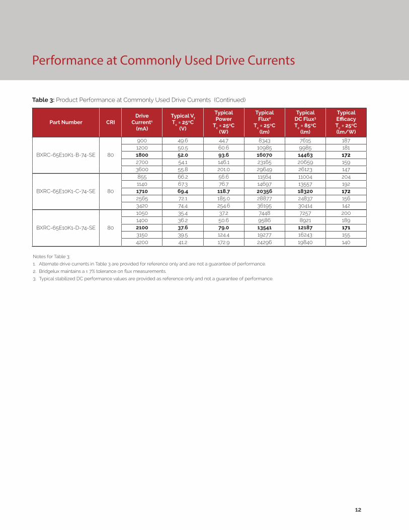
Notes for Table 3:
1. Alternate drive currents in Table 3 are provided for reference only and are not a guarantee of performance.
2. Bridgelux maintains a ± 7% tolerance on flux measurements.
3. Typical stabilized DC performance values are provided as reference only and not a guarantee of performance.
Table 3: Product Performance at Commonly Used Drive Currents (Continued)
Part Number CRIDrive
Current1
(mA)
Typical Vf Tc = 25ºC
(V)
Typical Power
Tc = 25ºC(W)
Typical Flux2
Tc = 25ºC(lm)
Typical DC Flux3 Tc = 85ºC
(lm)
Typical Efficacy Tc = 25ºC(lm/W)
BXRC-65E10K1-B-74-SE 80
900 49.6 44.7 8343 7615 1871200 50.5 60.6 10985 9985 1811800 52.0 93.6 16070 14463 1722700 54.1 146.1 23165 20659 1593600 55.8 201.0 29649 26123 147
BXRC-65E10K1-C-74-SE 80
855 66.2 56.6 11564 11004 2041140 67.3 76.7 14697 13557 1921710 69.4 118.7 20356 18320 1722565 72.1 185.0 28877 24837 1563420 74.4 254.6 36195 30414 142
BXRC-65E10K1-D-74-SE 80
1050 35.4 37.2 7448 7257 2001400 36.2 50.6 9586 8921 1892100 37.6 79.0 13541 12187 1713150 39.5 124.4 19277 16243 1554200 41.2 172.9 24296 19840 140
Electrical Characteristics
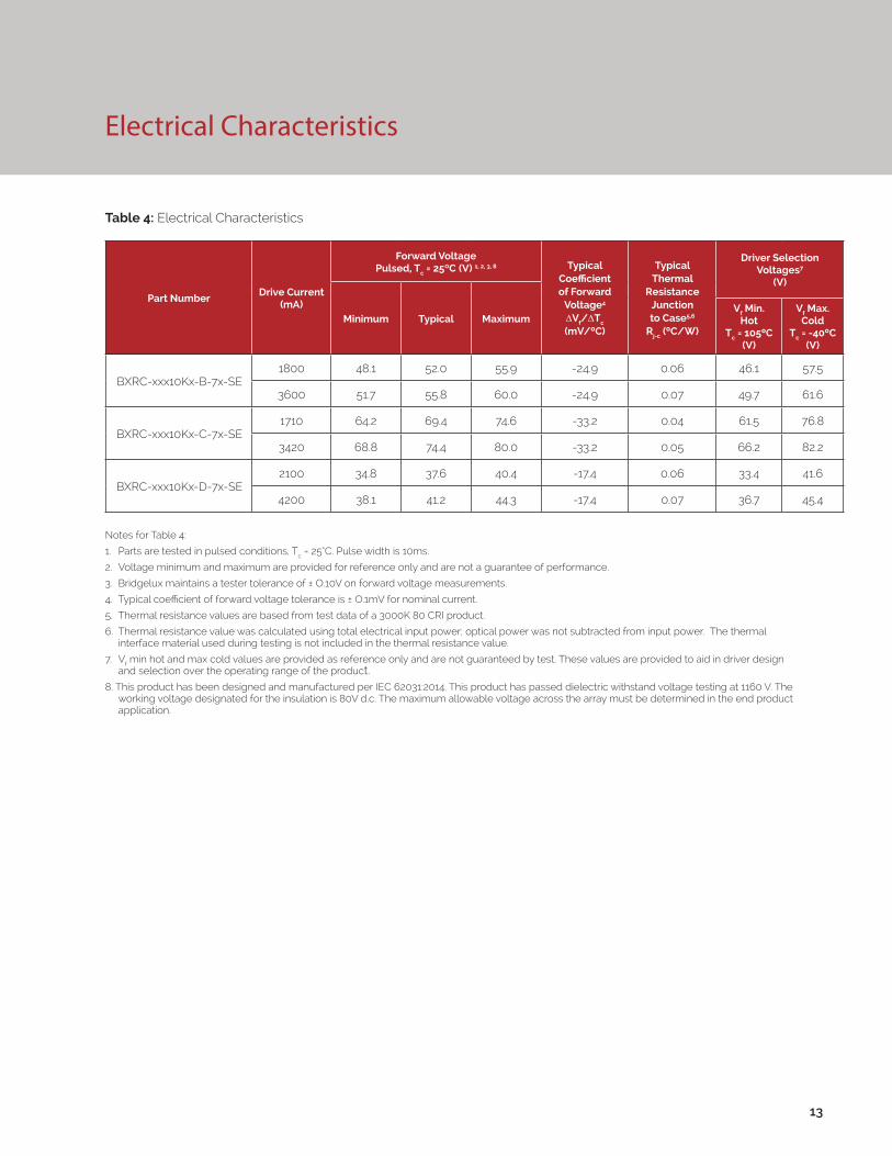
Notes for Table 4:
1. Parts are tested in pulsed conditions, Tc = 25°C. Pulse width is 10ms.
2. Voltage minimum and maximum are provided for reference only and are not a guarantee of performance.
3. Bridgelux maintains a tester tolerance of ± O.10V on forward voltage measurements.
4. Typical coefficient of forward voltage tolerance is ± O.1mV for nominal current.
5. Thermal resistance values are based from test data of a 3000K 80 CRI product.
6. Thermal resistance value was calculated using total electrical input power; optical power was not subtracted from input power. The thermal interface material used during testing is not included in the thermal resistance value.
7. Vf min hot and max cold values are provided as reference only and are not guaranteed by test. These values are provided to aid in driver design and selection over the operating range of the product.
8. This product has been designed and manufactured per IEC 62031:2014. This product has passed dielectric withstand voltage testing at 1160 V. The working voltage designated for the insulation is 80V d.c. The maximum allowable voltage across the array must be determined in the end product application.
Table 4: Electrical Characteristics
13
Part NumberDrive Current
(mA)
Forward VoltagePulsed, Tc = 25ºC (V) 1, 2, 3, 8 Typical
Coefficient of Forward
Voltage4 ∆Vf/∆Tc
(mV/ºC)
Typical Thermal
Resistance Junction to Case5,6
Rj-c (ºC/W)
Driver Selection Voltages7
(V)
Minimum Typical MaximumVf Min.
Hot Tc = 105ºC
(V)
Vf Max. Cold
Tc = -40ºC (V)
BXRC-xxx10Kx-B-7x-SE1800 48.1 52.0 55.9 -24.9 0.06 46.1 57.5
3600 51.7 55.8 60.0 -24.9 0.07 49.7 61.6
BXRC-xxx10Kx-C-7x-SE1710 64.2 69.4 74.6 -33.2 0.04 61.5 76.8
3420 68.8 74.4 80.0 -33.2 0.05 66.2 82.2
BXRC-xxx10Kx-D-7x-SE2100 34.8 37.6 40.4 -17.4 0.06 33.4 41.6
4200 38.1 41.2 44.3 -17.4 0.07 36.7 45.4
Eye Safety
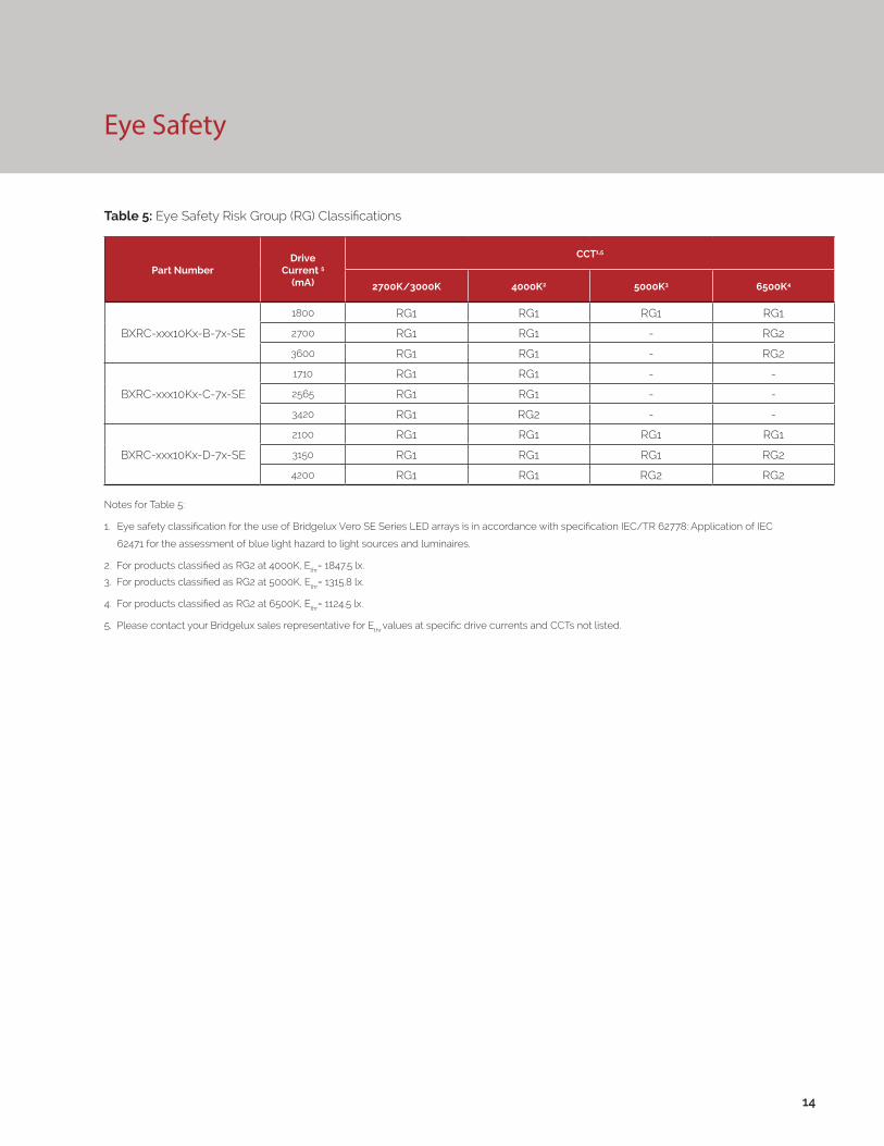
Notes for Table 5:
1. Eye safety classification for the use of Bridgelux Vero SE Series LED arrays is in accordance with specification IEC/TR 62778: Application of IEC
62471 for the assessment of blue light hazard to light sources and luminaires.
2. For products classified as RG2 at 4000K, Ethr= 1847.5 lx.
3. For products classified as RG2 at 5000K, Ethr= 1315.8 lx.
4. For products classified as RG2 at 6500K, Ethr= 1124.5 lx.
5. Please contact your Bridgelux sales representative for Ethr values at specific drive currents and CCTs not listed.
Table 5: Eye Safety Risk Group (RG) Classifications
14
Part NumberDrive
Current 5
(mA)
CCT1,5
2700K/3000K 4000K2 5000K3 6500K4
BXRC-xxx10Kx-B-7x-SE
1800 RG1 RG1 RG1 RG1
2700 RG1 RG1 - RG2
3600 RG1 RG1 - RG2
BXRC-xxx10Kx-C-7x-SE
1710 RG1 RG1 - -
2565 RG1 RG1 - -
3420 RG1 RG2 - -
BXRC-xxx10Kx-D-7x-SE
2100 RG1 RG1 RG1 RG1
3150 RG1 RG1 RG1 RG2
4200 RG1 RG1 RG2 RG2
15
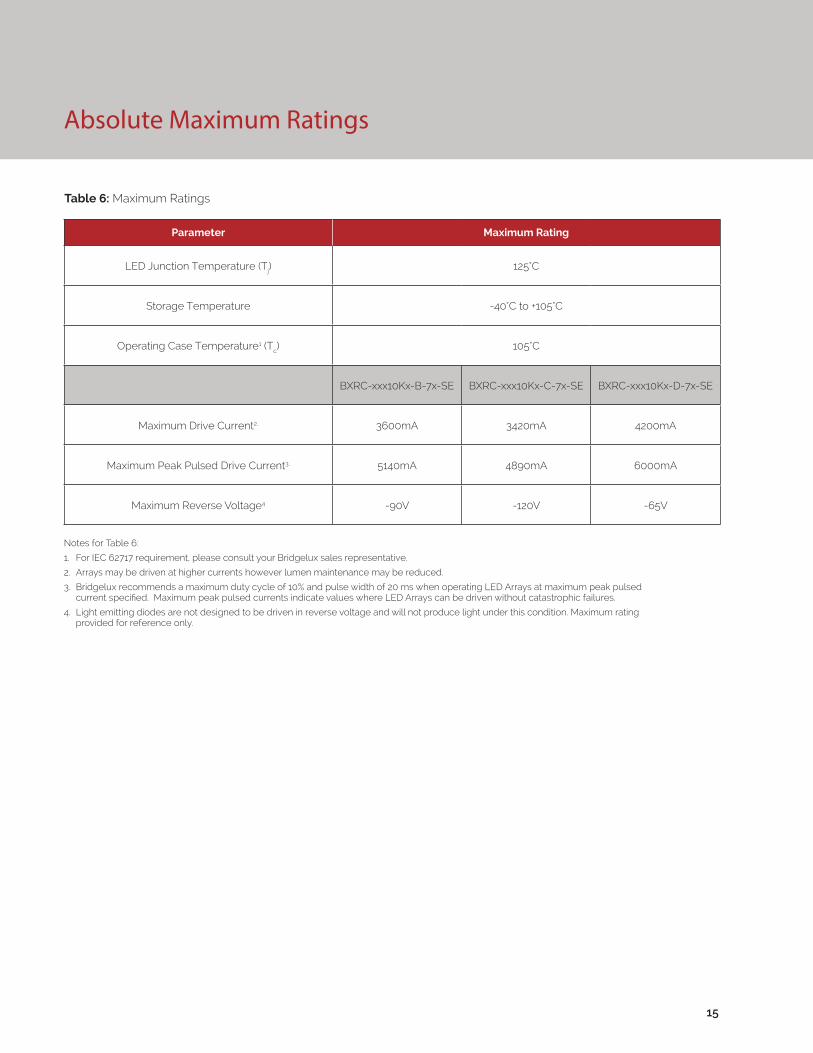
Absolute Maximum Ratings
Parameter Maximum Rating
LED Junction Temperature (Tj) 125°C
Storage Temperature -40°C to +105°C
Operating Case Temperature1 (Tc) 105°C
BXRC-xxx10Kx-B-7x-SE BXRC-xxx10Kx-C-7x-SE BXRC-xxx10Kx-D-7x-SE
Maximum Drive Current2, 3600mA 3420mA 4200mA
Maximum Peak Pulsed Drive Current3, 5140mA 4890mA 6000mA
Maximum Reverse Voltage4 -90V -120V -65V
Table 6: Maximum Ratings
Notes for Table 6:
1. For IEC 62717 requirement, please consult your Bridgelux sales representative.
2. Arrays may be driven at higher currents however lumen maintenance may be reduced.
3. Bridgelux recommends a maximum duty cycle of 10% and pulse width of 20 ms when operating LED Arrays at maximum peak pulsed current specified. Maximum peak pulsed currents indicate values where LED Arrays can be driven without catastrophic failures.
4. Light emitting diodes are not designed to be driven in reverse voltage and will not produce light under this condition. Maximum rating provided for reference only.
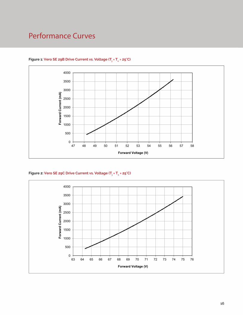
Performance Curves
Figure 1: Vero SE 29B Drive Current vs. Voltage (Tj = Tc = 25°C)
Figure 2: Vero SE 29C Drive Current vs. Voltage (Tj = Tc = 25°C)
16
0
500
1000
1500
2000
2500
3000
3500
4000
47 48 49 50 51 52 53 54 55 56 57 58
Forw
ard
Cur
rent
(mA)
Forward Voltage (V)
0
500
1000
1500
2000
2500
3000
3500
4000
63 64 65 66 67 68 69 70 71 72 73 74 75 76
Forw
ard
Cur
rent
(mA)
Forward Voltage (V)
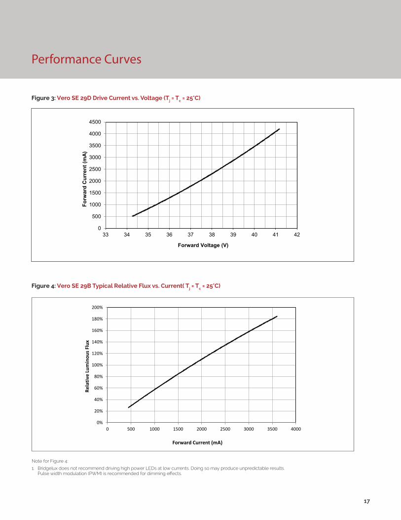
Performance Curves
Figure 3: Vero SE 29D Drive Current vs. Voltage (Tj = Tc = 25°C)
Figure 4: Vero SE 29B Typical Relative Flux vs. Current( Tj = Tc = 25°C)
17
Note for Figure 4:
1. Bridgelux does not recommend driving high power LEDs at low currents. Doing so may produce unpredictable results. Pulse width modulation (PWM) is recommended for dimming effects.
0%
20%
40%
60%
80%
100%
120%
140%
160%
180%
200%
0 500 1000 1500 2000 2500 3000 3500 4000
Rela
tive
Lum
inou
s Flu
x
Forward Current (mA)
0
500
1000
1500
2000
2500
3000
3500
4000
4500
33 34 35 36 37 38 39 40 41 42
Forw
ard
Cur
rent
(mA)
Forward Voltage (V)
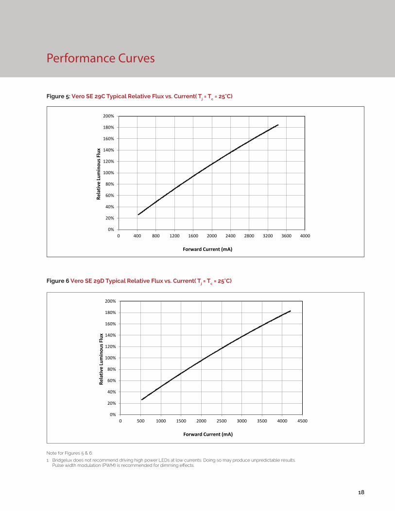
Performance Curves
Figure 5: Vero SE 29C Typical Relative Flux vs. Current( Tj = Tc = 25°C)
Figure 6 Vero SE 29D Typical Relative Flux vs. Current( Tj = Tc = 25°C)
18
Note for Figures 5 & 6:
1. Bridgelux does not recommend driving high power LEDs at low currents. Doing so may produce unpredictable results. Pulse width modulation (PWM) is recommended for dimming effects.
0%
20%
40%
60%
80%
100%
120%
140%
160%
180%
200%
0 400 800 1200 1600 2000 2400 2800 3200 3600 4000
Rela
tive
Lum
inou
s Flu
x
Forward Current (mA)
0%
20%
40%
60%
80%
100%
120%
140%
160%
180%
200%
0 500 1000 1500 2000 2500 3000 3500 4000 4500
Rela
tive
Lum
inou
s Flu
x
Forward Current (mA)
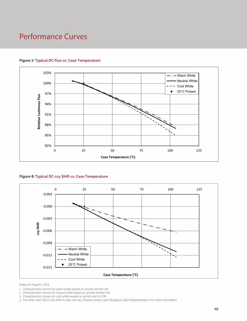
Figure 7: Typical DC Flux vs. Case Temperature
Figure 8: Typical DC ccy Shift vs. Case Temperature
19
Performance Curves
Notes for Figures 7 & 8:
1. Characteristics shown for warm white based on 3000K and 80 CRI.2. Characteristics shown for neutral white based on 4000K and 80 CRI.3. Characteristics shown for cool white based on 5000K and 70 CRI.4. For other color SKUs, the shift in color will vary. Please contact your Bridgelux Sales Representative for more information.
82%
85%
88%
91%
94%
97%
100%
103%
0 25 50 75 100 125
Rela
tive
Lum
inou
s Flu
x
Case Temperature (°C)
Warm WhiteNeutral WhiteCool White25°C Pulsed
-0.015
-0.012
-0.009
-0.006
-0.003
0.000
0.0030 25 50 75 100 125
ccy
Shift
Case Temperature (°C)
Warm WhiteNeutral WhiteCool White25°C Pulsed
Performance Curves
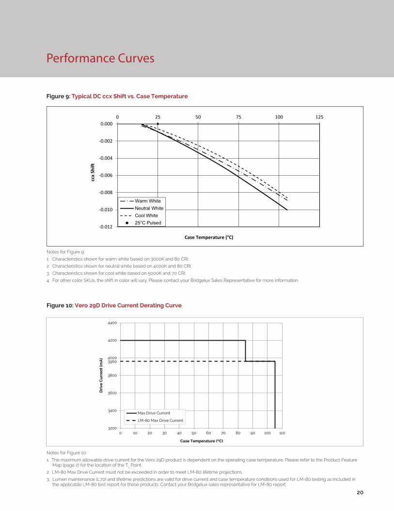
Figure 9: Typical DC ccx Shift vs. Case Temperature
20
Notes for Figure 9:
1. Characteristics shown for warm white based on 3000K and 80 CRI.
2. Characteristics shown for neutral white based on 4000K and 80 CRI.
3. Characteristics shown for cool white based on 5000K and 70 CRI.
4. For other color SKUs, the shift in color will vary. Please contact your Bridgelux Sales Representative for more information.
-0.012
-0.010
-0.008
-0.006
-0.004
-0.002
0.0000 25 50 75 100 125
ccx
Shift
Case Temperature (°C)
Warm WhiteNeutral WhiteCool White25°C Pulsed
Figure 10: Vero 29D Drive Current Derating Curve
Notes for Figure 10:
1. The maximum allowable drive current for the Vero 29D product is dependent on the operating case temperature. Please refer to the Product Feature Map (page 2) for the location of the Tc Point
2. LM-80 Max Drive Current must not be exceeded in order to meet LM-80 lifetime projections.
3. Lumen maintenance (L70) and lifetime predictions are valid for drive current and case temperature conditions used for LM-80 testing as included in the applicable LM-80 test report for these products. Contact your Bridgelux sales representative for LM-80 report.
3200
3400
3600
3800
4000
4200
4400
0 10 20 30 40 50 60 70 80 90 100 110
Dri
ve C
urr
en
t (m
A)
Case Temperature (⁰C)
Max Drive Current
LM-80 Max Drive Current
3960
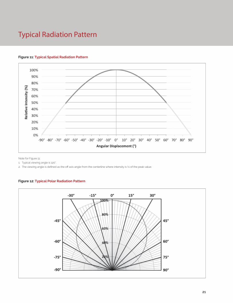
Typical Radiation Pattern
Figure 11: Typical Spatial Radiation Pattern
Figure 12: Typical Polar Radiation Pattern
21
Note for Figure 11:
1. Typical viewing angle is 120⁰.
2. The viewing angle is defined as the off axis angle from the centerline where intensity is ½ of the peak value.
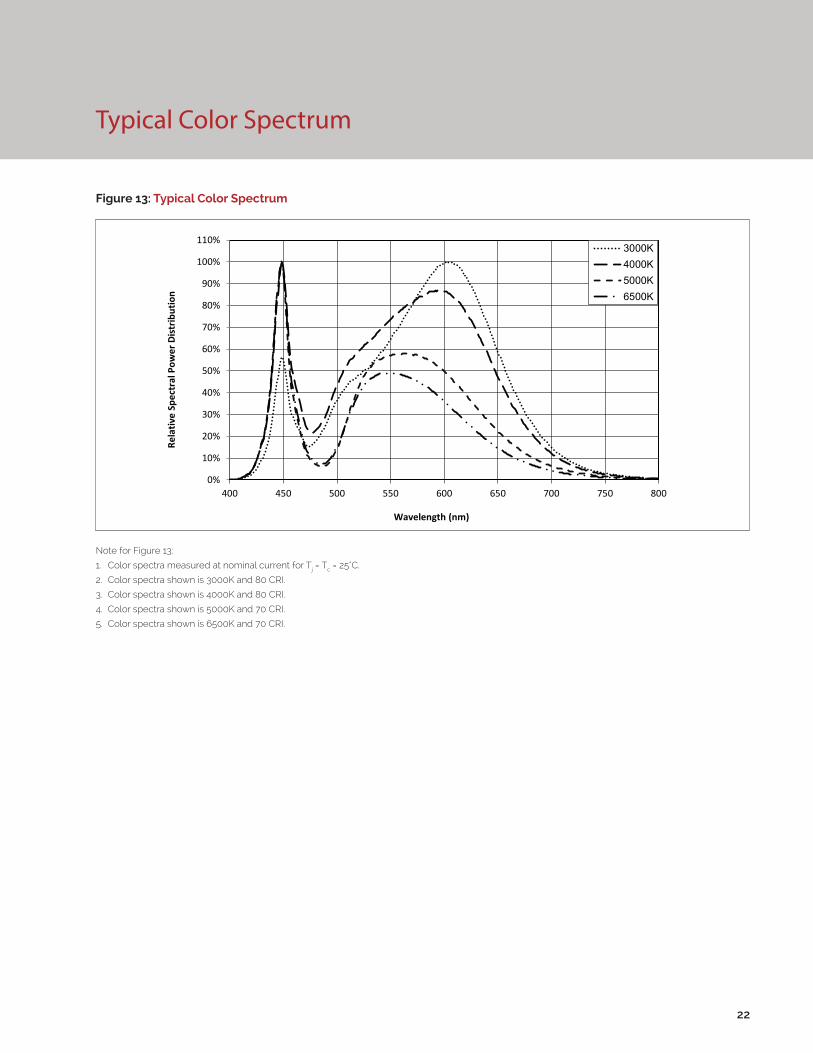
Typical Color Spectrum
Figure 13: Typical Color Spectrum
22
Note for Figure 13:
1. Color spectra measured at nominal current for Tj = Tc = 25°C.
2. Color spectra shown is 3000K and 80 CRI.
3. Color spectra shown is 4000K and 80 CRI.
4. Color spectra shown is 5000K and 70 CRI.
5. Color spectra shown is 6500K and 70 CRI.
0%
10%
20%
30%
40%
50%
60%
70%
80%
90%
100%
110%
400 450 500 550 600 650 700 750 800
Rela
tive
Spec
tral
Pow
er D
istr
ibut
ion
Wavelength (nm)
3000K4000K5000K6500K
Mechanical Dimensions
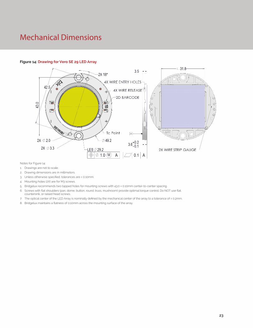
Figure 14: Drawing for Vero SE 29 LED Array
23
Notes for Figure 14:
1. Drawings are not to scale.
2. Drawing dimensions are in millimeters.
3. Unless otherwise specified, tolerances are ± 0.10mm.
4. Mounting holes (2X) are for M3 screws.
5. Bridgelux recommends two tapped holes for mounting screws with 43.0 ± 0.10mm center-to-center spacing.
6. Screws with flat shoulders (pan, dome, button, round, truss, mushroom) provide optimal torque control. Do NOT use flat, countersink, or raised head screws.
7. The optical center of the LED Array is nominally defined by the mechanical center of the array to a tolerance of ± 0.2mm.
8. Bridgelux maintains a flatness of 0.10mm across the mounting surface of the array.
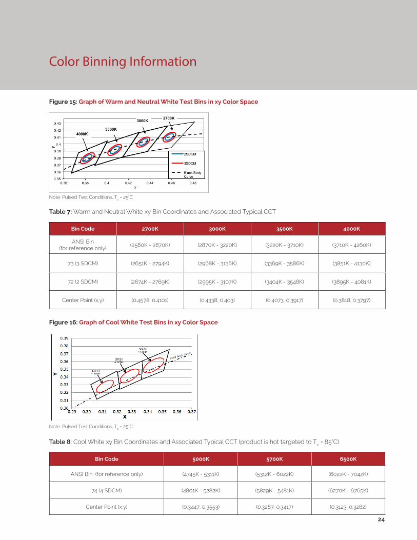
Figure 15: Graph of Warm and Neutral White Test Bins in xy Color Space
Figure 16: Graph of Cool White Test Bins in xy Color Space
Color Binning Information
Bin Code 2700K 3000K 3500K 4000K
ANSI Bin(for reference only)
(2580K - 2870K) (2870K - 3220K) (3220K - 3710K) (3710K - 4260K)
73 (3 SDCM) (2651K - 2794K) (2968K - 3136K) (3369K - 3586K) (3851K - 4130K)
72 (2 SDCM) (2674K - 2769K) (2995K - 3107K) (3404K - 3548K) (3895K - 4081K)
Center Point (x,y) (0.4578, 0.4101) (0.4338, 0.403) (0.4073, 0.3917) (0.3818, 0.3797)
Table 7: Warm and Neutral White xy Bin Coordinates and Associated Typical CCT
Bin Code 5000K 5700K 6500K
ANSI Bin (for reference only) (4745K - 5311K) (5312K - 6022K) (6022K - 7042K)
74 (4 SDCM) (4801K - 5282K) (5829K - 5481K) (6270K - 6765K)
Center Point (x,y) (0.3447, 0.3553) (0.3287, 0.3417) (0.3123, 0.3282)
Table 8: Cool White xy Bin Coordinates and Associated Typical CCT (product is hot targeted to Tc = 85°C)
Note: Pulsed Test Conditions, Tc = 25°C
Note: Pulsed Test Conditions, Tc = 25°C
24
Packaging and Labeling
25
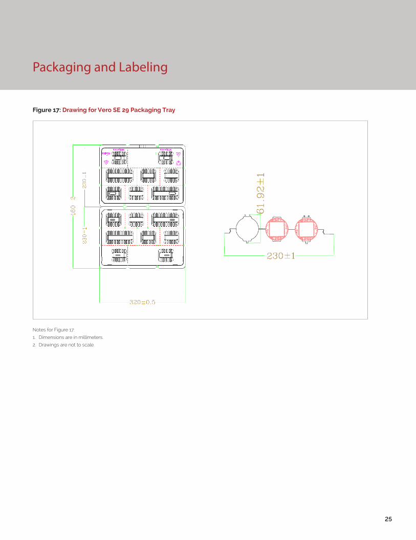
Figure 17: Drawing for Vero SE 29 Packaging Tray
Notes for Figure 17:
1. Dimensions are in millimeters.
2. Drawings are not to scale.
Packaging and Labeling
26
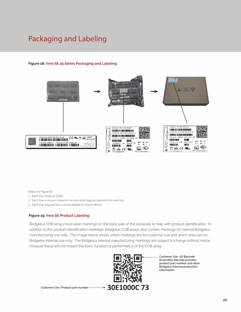
Figure 18: Vero SE 29 Series Packaging and Labeling
Notes for Figure 18:
1. Each tray holds 50 COBs.
2. Each tray is vacuum sealed in an anti-static bag and placed in its own box.
3. Each tray, bag and box is to be labeled as shown above.
Figure 19: Vero SE Product Labeling
Bridgelux COB arrays have laser markings on the back side of the substrate to help with product identification. In
addition to the product identification markings, Bridgelux COB arrays also contain markings for internal Bridgelux
manufacturing use only. The image below shows which markings are for customer use and which ones are for
Bridgelux internal use only. The Bridgelux internal manufacturing markings are subject to change without notice,
however these will not impact the form, function or performance of the COB array.
Customer Use- 2D Barcode Scannable barcode provides product part number and other Bridgelux internal production information.
Customer Use- Product part number 30E1000C 73
Design Resources
Disclaimers
Precautions
Optical Source Models
Optical source models and ray set files are available for all Bridgelux products. Please contact your Bridgelux sales representative for assistance.
3D CAD Models
Three dimensional CAD models depicting the product outline of all Bridgelux Vero SE LED arrays are available in both IGS and STEP formats. Please contact your Bridgelux sales representative for assistance.
MINOR PRODUCT CHANGE POLICY
The rigorous qualification testing on products offered by Bridgelux provides performance assurance. Slight cosmetic changes that do not affect form, fit, or function may occur as Bridgelux continues product optimization.
CAUTION: CHEMICAL EXPOSURE HAZARD
Exposure to some chemicals commonly used in luminaire manufacturing and assembly can cause damage to the LED array. Please consult Bridgelux Application Note AN31 for additional information.
CAUTION: RISK OF BURN
Do not touch the Vero SE LED array during operation. Allow the array to cool for a sufficient period of time before handling. The Vero SE LED array may reach elevated temperatures such that could burn skin when touched.
LM80
LM80 testing has been completed and the LM80 report is now available. Please contact your Bridgelux sales representative for LM-80 report.
27
CAUTION
CONTACT WITH LIGHT EMITTING SURFACE (LES)
Avoid any contact with the LES. Do not touch the LES of the LED array or apply stress to the LES (yellow phosphor resin area). Contact may cause damage to the LED array.
Optics and reflectors must not be mounted in contact with the LES (yellow phosphor resin area). Optical devices may be mounted on the top surface of the plas-tic housing of the Vero SE LED array. Use the mechanical features of the LED array housing, edges and/or mounting holes to locate and secure optical devices as needed.
STANDARD TEST CONDITIONS
Unless otherwise stated, array testing is performed at the nominal drive current.
28
About Bridgelux: We Build Light That Transforms
© 2016 Bridgelux, Inc. All rights reserved 2016. Product specifications are subject to change without notice. Bridgelux, the Bridgelux stylized logo design and Vero are registered trademarks of Bridgelux, Inc. All other trademarks are the property of their respective owners.
Bridgelux Vero SE 29 Array Product Data Sheet DS123 Rev. B (12/2016)
101 Portola Avenue
Livermore, CA 94551
Tel (925) 583-8400
www.bridgelux.com
At Bridgelux, we help companies, industries and people experience the power and possibility of light. Since 2002, we’ve designed LED solutions that are high performing, energy efficient, cost effective and easy to integrate. Our focus is on light’s impact on human behavior, deliver-ing products that create better environments, experiences and returns—both experiential and financial. And our patented technology drives new platforms for commercial and industrial luminaires.
For more information about the company, please visit bridgelux.comtwitter.com/Bridgeluxfacebook.com/Bridgeluxwww.linkedin.com/company/bridgelux-inc-_2WeChat ID: BridgeluxInChina