Embed Size (px)
Citation preview

Chapter I I – The const ruct ion and demol i t ion waste, i ts recycl ing and reuse opportuni t ies
276
BREAKWATER WALLS IN NEIGHBORHOODS
1Jaramillo-Morilla, A.; 1Mascort-Albea, E.J; 1Díaz-Pichardo, A.; 1Bernabe-Reyes, C.; 1Villicaña-Cupa, M.A.; 1Contreras-Marín, E.; 1Díaz-Calderón, G.
1Departamento de Estructuras de Edificación e Ingeni ería del Terreno, Universidad de Sevilla E.T.S.
Arquitectura, Avd. Reina Mercedes, nº2, 41012-Sevil la e-mail: [email protected], [email protected], adpfic18000@h otmail.com, [email protected], elangelcaido_162@ho tmail.com,
[email protected], tapilu99@hotmail .com.
ABSTRACT
The uneven and slopes terrain force us to intervene with rigid or flexible containment structures. Containment structures tend to be mostly of reinforced concrete or steel sheet piling. For some time, the use of stone jetties as containment structures and permanent stabilization in housing estates is being imposed. This type of structure has been used successfully in slopes of roads and jetties on port. When moving it to suburbia has disparaged some aspects, both design and calculation, not taking into account actions in risk areas, or eliminating essential components as filters and drain components. This document analyzes the work of intervention in two works affected in Motril (Granada, Spain) and Almeria (Spain), where the breakwaters were utilized, reaching recidivism in one of them. Guide for the design and construction of breakwaters in roadworks from the Ministry of Public Works in 1998, revised in 2006, [3] is a valuable document but requires a Decalogue of specific instructions for use in works of urbanization, in general of lower volume, and with the largest number of meetings of surfaces. Three-dimensionality is usually an important factor to take into account. Keywords: breakwaters, seismic action, earth pressures
Proceedings of the I I Internat ional and IV Nat ional Congress on Sustainable Construct ion and Eco-Ef f ic ient Solut ions
277
1.- Introduction To save slopes and terrain variations when required to do a construction is necessary to implement a method of containment. Breakwater walls are a good option in these cases as long as they are performed correctly counting with previous studies of the land where you go to place and making a correct design and construction process thereof. These types of walls have certain advantages over a contention wall of another type, for example, easy to drain water from the land that is holding, good adaptability to small differential ground movements without suffering structural damage and especially good integration with the environment, since they are built with natural materials. However omitting small basic details in design and construction can lead to stability problems as those reviewed in this paper. 2.- Background of the problem This paper is written in order to explain the causes of the problems that were presented in two breakwater walls built in Motril and Almeria (Spain). Besides various solutions for each particular case are proposed, thus trying to eradicate the problem. 2.1.- Study cases The first case to be analyzed is an urbanization in Motril (Spain), where walls jetties were used in different places and for different purposes, it is the construction of two buildings in which the uneven ground was used to build a plant basement to serve as vehicles parking, building on the wall of this uneven terrain breakwater wall for stability and control of the land. Breakwater walls were also built throughout a drainage channel which is intended to stabilize the walls of the channel and prevent soil erosion by water flow. The damage that occurred are described in the report by Jaramillo [1, 2]. The second case study is a house on the plot No. 52 in Envía Golf located in Almeria (Spain) (Jaramillo, 2003 and 2011) [4, 5]. The plot originally had an area of 1383 m² this according to a topographic survey done in January 1994, this area was increased by the developer in more than 2.3 times its original extent at the expense of occupying boundaries and free zones of urbanization in slope natural, to perform this increase was cut existing hill in the field and grading the resulting cutting material producing slopes of more than 10 meters high, in which a jetty wall was constructed in order to provide support and stability to the ground, but note that this wall did not have the minimum requirements of stability and geometry necessary and material behind the wall it was saturated due to leaks in the supply system and irrigation of the plot, so slippage slope problem was presented. 3.- Design methodology For a jetty wall fulfills its purpose is to provide stability and support to a embankment or slope in the field should be considered and designed as a contention wall of gravity and it must meet several conditions such as: geometric, physical, mechanical and durability. To this end we have the document "Guidelines for the design and execution of rubble walls in road construction", latest version 2009 [3], which provides a series of recommendations for design, construction methods and right choice materials used. As mentioned in the title of the document, these recommendations were created for the use of jetties in highways works, however these can be transferred to the construction of breakwaters on developments, but it is important not to forget the important aspects of security and design.

Chapter I I – The const ruct ion and demol i t ion waste, i ts recycl ing and reuse opportuni t ies
278
3.1.- Geometrical conditions The basic geometric conditions recommended consist of horizontal rows placed successively that present reasons for slope around 3H / 1V, so submit regular contact faces enough to allow the correct support of the top course. It is also recommended that each course is constituted with a minimum of 2 pieces in thickness and the minimum size of the base not less than 2.00 m.
Fig 1 “Breakwater Wall Scheme”. "Guidelines for the design and execution of rubble walls in road construction" Ministerio de Fomento.
3.2.- Physical and mechanical properties Depending on the particle size of the pieces we can distinguish:
- Thick Breakwater HMB1000 / 3000, consisting of pieces whose mass is between 1000 and 3000 kg., Especially recommended for the jetties "placed" described.
- Thick Breakwater HMB 300 / 1000, with masses are between 300 and 1000 kg., Recommended for jetties reduced or as filler for breakwaters formed by parts of the previous group height.
The most appropriate way is the prismatic blocks with rough surfaces, specifically avoiding smooth or rounded shapes. In the "Guide for the Design and Implementation of walls in Breakwater Road Works", 2009, a formal limitation on the use of parts according to prismatic condition is set, setting the maximum percentage of parts that can maintain a ratio (L / E> 3) ≤ 15% being:
- L block largest dimension of a breakwater. - E block minimum size of a breakwater.
Based on the collaboration necessary friction between parts, blocks must submit rough plans, with fracture faces and sharp edges, limiting the percentage of rounded surfaces ≤ 5% RO RO ratio being crushed or broken surfaces as test UNE EN 13383 -1. The specific gravity of the materials particularly influence the behavior of the breakwater, it is therefore recommended that is not less than 2500 kg / m³, a medium resistance presenting in compression simple test above 80 MPa, with a percentage higher than 60 % of components that provide a value above 60 MPa. Resistance to fragmentation is checked by the test of Los Angeles (UNE EN 1097-2), obtaining values of LA <35.
Proceedings of the I I Internat ional and IV Nat ional Congress on Sustainable Construct ion and Eco-Ef f ic ient Solut ions
279
3.3.- Design method The design of a breakwater wall must respond to verification of the main failure criteria that correspond to:
- Sliding - Sinking - Global stability - Local stability
As mentioned previously breakwater walls behave as a gravity wall, thus checking the exposed first three modes of failure is calculated the same way as these. Therefore in this study only the failure mode of local stability is explained. By local failure mode stability identify a breakage method whereby mobilizes a part of the ground filler contained in a breaking plane that cuts the wall, causing a portion thereof (upper) to move over another that freezes (bottom). Using the methodology of Mohr-Coulomb and considering a cohesive material (c = 0) we can make a good approach to real working conditions. And so the only resistant parameter that we focus on is the friction between the elements. Recalling the recommendation of placing the pieces with an opposite slope 3H: 1V with respect to the horizontal, we can ensure for rupture at a certain height is necessary forces to bear exceed the frictional forces generated occurs on the inclined plane ascending on which they rest. A system for determining the safety factor may be established based on the relationship between the fracture surface and intersecting the wall angle of the spun opposite slope arranged. Thus, the entire fracture surface to have a different exit angle of breakage determined blocks thereof. It will therefore be necessary to analyze how many break lines deemed to ensure that the breakwater wall angles derived adopt execution. It will be therefore essential to determine the angle of internal friction of the jetty (φ), considering that in its evaluation can influence certain factors that allow to establish:
φ = φb + ∆φe - ∆φn (1)
Where: Φb basic angle value friction material, and that based on the recommended compression resistance (greater than qu> 80 MPa average) allows for a range of 42 ° <φ <38 °. ∆φe increased value can be determined by favorable effect which causes a correct execution of the wall, allowing good friction between the parts. Can be considered to be necessary that the vertical surface is steeper than 1H: 3V,that maintain an average opposite slope rows 3H: 1V, the average crown thickness not less than 2.00 m. and that the cross section has at least 2 pieces. Under these conditions may be determined 1% <∆φe <3%. ∆φn decrease in the value of the angle of friction as a function of normal stress, which can be estimated from: ∆φn = φn· log10 (σn / Pa) ≥ 0 Where: φn factor which is expressed in degrees, so that φn ≥ 7. σn normal maximum stress to that is subjected the section. Pa atmospheric pressure can be estimated in reference to P = 0.1 MPa. Φb values and ∆φe may be deducted from the following table:
Chapter I I – The const ruct ion and demol i t ion waste, i ts recycl ing and reuse opportuni t ies
280
TYPE OF ROCK φb (º) ∆φe (º) Very healthy Granite 40-41 1-2 Gneis 41-42 1-2 Quarzite 39-40 1-2 Basalt 40-41 1-3 Rhyolite, Andesite 41-42 1-3 Syenite, granodiorite and diotita 39-40 1-3 Conglomerates and tightly closed gaps 39-41 1-2 Very cemented sandstone 38-39 1-2
Table 1 “Evaluation of basic friction angle and increased by favorable effect of execution”
Getting values for compacted rockfill according to performance conditions exposed that can be expressed based on the recommendations in the table below:
TIPO DE ROCA φmin (º) φmed (º) φmax (º) Granite 37 41 45 Gneis 40 43 45 Quarzite 36 39 42 Basalt 37 41 45 Rhyolite, Andesite 39 42 46 Syenite, granodiorite and diotita 38 42 46 Dolomites and limestones very healthy 38 40 43 Sandstone 33 37 42
Table 2 “Range of angles of internal friction of the jetty by material”. 4.- Representation and damage registration In the urbanization of Motril (Spain), the construction of the breakwater was in several areas (under buildings, no construction zone and channel) so the problems presented were different and then listed.
- Appearance of fissures in the firm and in the concrete that mark a line of descent ground parallel to breakwater line.
- Level differences between different parts of the pavement.
- At the top of the outer face of the breakwater cracks are observed parallel to breakwater line.
- Breakage of stones due to lack of sufficient flatness conditions. There is no ground plane of the stones, which causes the appearance of occasional support which carries the occurrence of high stresses and lack of stability.
- Displacement of stones.
- Rockfall in the channel.
- Washing ground between the stones which caused the appearance of significant gaps in different areas of urbanization (caverns)so producing holes under the bicycle lane.
- Investment of the slope on the bike path and the sidewalks, causing the accumulation of water as puddles.

Proceedings of the I I Internat ional and IV Nat ional Congress on Sustainable Construct ion and Eco-Ef f ic ient Solut ions
281
All observed damage in an area of 2-4 meters behind the breakwater and along the same, so it is clear that the problem lies in the poor design of the breakwater.
Fig 2 “Fracture of rocks by overstressing” and Fig 3 “Subsidence”
Fig 4 “Seating and slope change” and Fig
5 “Falling rocks at the breakwater channel”
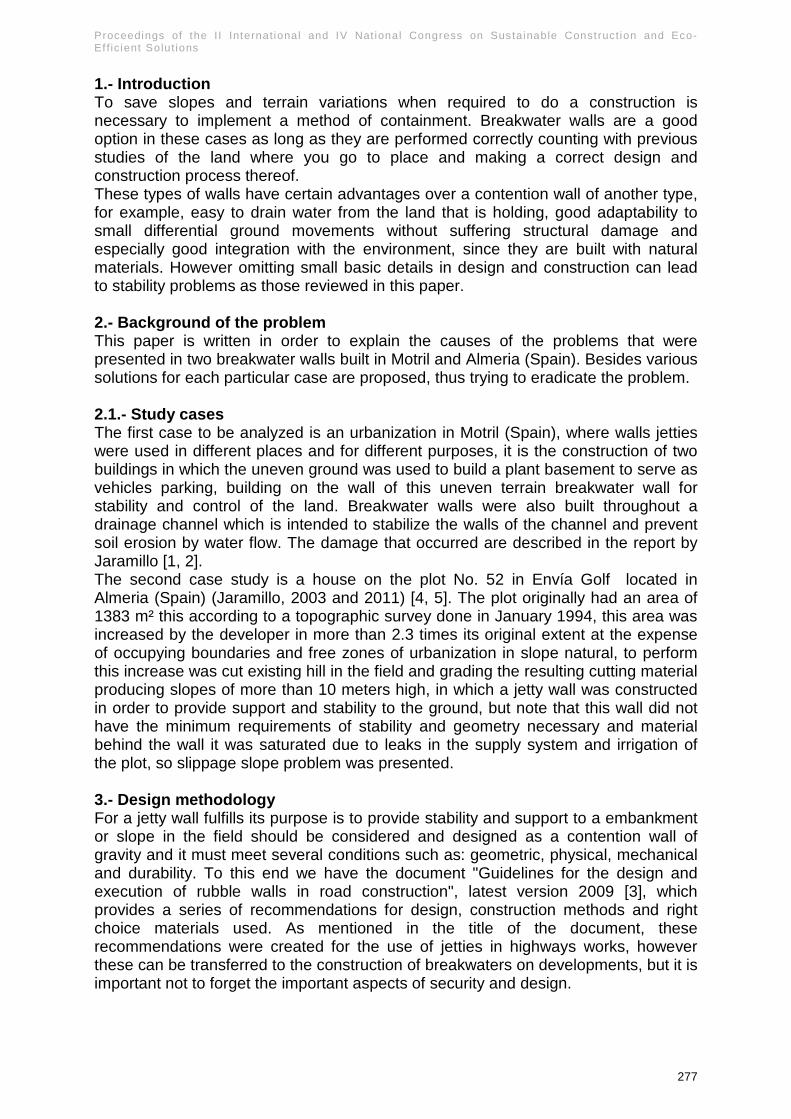
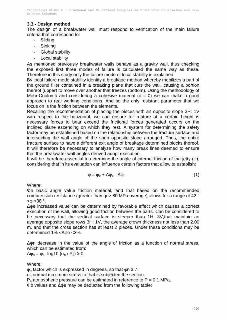
As mentioned above, in the construction of Envía Golf in Almeria (Spain), the plot No. 52 in a little over 1300 m² was increased to over 3000 m² generating the new perimeter of the plot a steep slope of more than 10 meters and with an almost vertical slope, where breakwater wall was constructed, which by its poor stability characteristics can not be considered as such, since it is only a wall covering (skin type breakwater) which has a too low or almost zero resistance to pushes and ground displacements.
Fig 6 “Deficient breakwater wall” and Fig 7 “Ground movement and sliding wall”
Chapter I I – The const ruct ion and demol i t ion waste, i ts recycl ing and reuse opportuni t ies
282
Fig 8 “Landslide” and Fig 9 “Landslide”
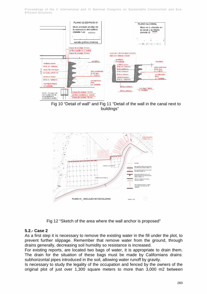
5.- Proposed solutions 5.1.- Case 1 As corrective measures we propose three solutions on areas.
- For the breakwater area under commercial buildings already constructed propose the realization of a concrete wall to line the breakwater supporting the lining 30 cm thick mesh of 16-20 on both sides of to the slab and foundation.
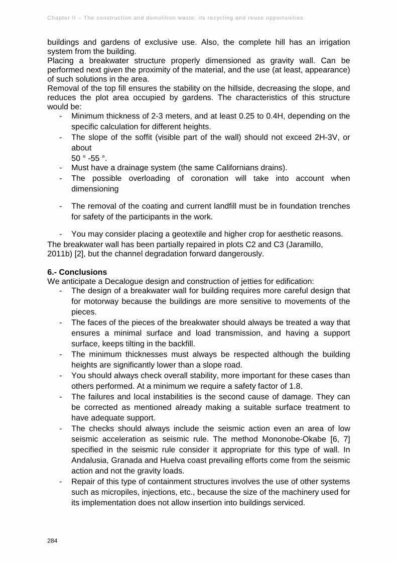
- For the breakwater area where the building is not expected, the placement of anchors.
- For the area of breakwater in the free zone currently building, but where it is planned to build, recommend performing a reinforced concrete coating of 30 cm and 16 to 20 mesh, monitoring the movement of the wall by surveyors. In this way we can control whether the coating, making the breakwater work as a whole is sufficient or not. In case of movement in the next six months, anchor the wall to the building, where he will support the structure.
- For the Canal Zone, we propose two solutions:
- Intubate with a minimum equivalent section for the avenues. According to comments made by the owner, it could be a section of 1 m2 pipe that surround of land terracing surface with a slight slope, given the current variable gap between the two banks of the canal.
- Reinforcement with a wall in L at the edge of bicycle lane and gunning in the opposite. The reinforcement we have calculated is somewhat lower, 25 cm thick, round 16 and 12 being the lower height, function as a wall in L against the opposite shore.
Also, on the area of the new concrete wall, protecting the breakwater, should be placed mesh protection against falling material to the parking. It is important to maintain drainage through the new concrete walls for protection. Other corrective measures include injecting of urbanization in 4 meters behind the breakwater. The penetrometer made these days detect the absence of material (soil) under the floor, so that subsidence and caverns may occur.
Proceedings of the I I Internat ional and IV Nat ional Congress on Sustainable Construct ion and Eco-Ef f ic ient Solut ions
283
Fig 10 “Detail of wall” and Fig 11 “Detail of the wall in the canal next to
buildings”
Fig 12 “Sketch of the area where the wall anchor is proposed”
5.2.- Case 2 As a first step it is necessary to remove the existing water in the fill under the plot, to prevent further slippage. Remember that remove water from the ground, through drains generally, decreasing soil humidity so resistance is increased. For existing reports, are located two bags of water, it is appropriate to drain them. The drain for the situation of these bags must be made by Californians drains: subhorizontal pipes introduced in the soil, allowing water runoff by gravity. Is necessary to study the legality of the occupation and fenced by the owners of the original plot of just over 1,300 square meters to more than 3,000 m2 between
Chapter I I – The const ruct ion and demol i t ion waste, i ts recycl ing and reuse opportuni t ies
284
buildings and gardens of exclusive use. Also, the complete hill has an irrigation system from the building. Placing a breakwater structure properly dimensioned as gravity wall. Can be performed next given the proximity of the material, and the use (at least, appearance) of such solutions in the area. Removal of the top fill ensures the stability on the hillside, decreasing the slope, and reduces the plot area occupied by gardens. The characteristics of this structure would be:
- Minimum thickness of 2-3 meters, and at least 0.25 to 0.4H, depending on the specific calculation for different heights.
- The slope of the soffit (visible part of the wall) should not exceed 2H-3V, or about 50 ° -55 °.
- Must have a drainage system (the same Californians drains). - The possible overloading of coronation will take into account when
dimensioning
- The removal of the coating and current landfill must be in foundation trenches for safety of the participants in the work.
- You may consider placing a geotextile and higher crop for aesthetic reasons. The breakwater wall has been partially repaired in plots C2 and C3 (Jaramillo, 2011b) [2], but the channel degradation forward dangerously. 6.- Conclusions We anticipate a Decalogue design and construction of jetties for edification:
- The design of a breakwater wall for building requires more careful design that for motorway because the buildings are more sensitive to movements of the pieces.
- The faces of the pieces of the breakwater should always be treated a way that ensures a minimal surface and load transmission, and having a support surface, keeps tilting in the backfill.
- The minimum thicknesses must always be respected although the building heights are significantly lower than a slope road.
- You should always check overall stability, more important for these cases than others performed. At a minimum we require a safety factor of 1.8.
- The failures and local instabilities is the second cause of damage. They can be corrected as mentioned already making a suitable surface treatment to have adequate support.
- The checks should always include the seismic action even an area of low seismic acceleration as seismic rule. The method Mononobe-Okabe [6, 7] specified in the seismic rule consider it appropriate for this type of wall. In Andalusia, Granada and Huelva coast prevailing efforts come from the seismic action and not the gravity loads.
- Repair of this type of containment structures involves the use of other systems such as micropiles, injections, etc., because the size of the machinery used for its implementation does not allow insertion into buildings serviced.
Proceedings of the I I Internat ional and IV Nat ional Congress on Sustainable Construct ion and Eco-Ef f ic ient Solut ions
285
- The nearby buildings can support some of pushes of the walls contributing to its stabilization, being fixed items in three dimensions. 5 to 10% of the dead load may stabilize a breakwater wall.
- It is essential to specify the drainage elements: breakwater backfill material, dimension of holes and drainage pipes, avoid accumulation zones, etc.
- Given the dimensions of the elements during construction, and in case of repair, the proximity of workers should be avoided because of the danger of collapse of large parts. At least secure loose items before any action.
ACKNOWLEDGEMENTS Especially grateful for the work and interest to doctors Wilfrido Martínez, Molina Elia Mercedes Alonso Guzmán, Teachers of Fac. de Ing. Civil, and to the doctor Carlos Alberto Hiriart Pardo of the Fac. de Arquitectura, all the UMSNH of Morelia de México, for having laid a bridge between Morelia and Seville, allowing and encouraging the exchange of students in master. Acknowledge the support of the University of Seville, his IPPV has helped fund the efforts of this document. REFERENCES [1] Jaramillo Morilla, Antonio, 2011a. “Informe sobre patologías de la urbanización de la UE-13 de Motril Granada”. Informe sin publicar. Encargo Junta de Compensación. [2] Jaramillo Morilla, Antonio, 2011b. “Proyecto de reparación de muros de urbanización en parcelas C2 y C3 de la UE MOT 13 de Motril”. Proyecto visado COA de Granada. Encargo Junta de Compensación. [3] Guía de escolleras, 2009. Guía para el proyecto y la ejecución de muros de escollera en obras de carretera. 3ª edición revisada 2009. [4] Jaramillo Morilla, Antonio 2012. “Informe sobre vivienda parcela 52, urbanización la Envía Golf en Vícar, Almería, Encargo ASEMAS. Informe sin publicar. [5] Jaramillo Morilla, Antonio 2001. “Informe sobre vivienda parcela 52, urbanización la Envía Golf en Vícar, Almería, Encargo ASEMAS. Informe sin publicar. [6] Mononobe N, Matsuo H., 1929. “On the determination of earth pressure during earthquakes. In Proc. Of the World Engineering Conf., Vol. 9, str. 176. [7] Okabe, S 1926. “General theory of earth pressure. Journal of the Japanese Society of civil Engineers”. tokz, Japan 12 (1).