Embed Size (px)
Citation preview
Bhagwan mahavir college of Engineering & Technology, Surat.
Department of automobile Engineering
Assignment
Subject: Machine Design & Industrial Drafting
B.E. – Second year
Instructions:
1. This set of tutorial consists of collection of all past GTU papers & important examples.
2. Students should maintain note book to solve these assignment..
3. Students should solve this assignment themselves
4. Students should regularly get assessed all the assignment with respective faculty members.
5. Do not write the answers of repeated questions.
Chapter Sr. Question Mark Paper
Introduction
1 What is factor of safety? List the factors to be considered for deciding the magnitude of factor of safety?
02 MARCH
2010
2 What is stress concentration? How will you reduce the stress concentration in keyway shaft and in threaded parts?
04 MARCH
2010
3 Differentiate between (with neat sketch): 1) crushing and compressive stresses 2) torsional and transverse shear stress
04
DEC 2010
4
Define the following : 1) proof resilience 2) Preferred Number 3)Factor of Safety 4)Residual stress 5) principle stress
05
DEC 2010
5
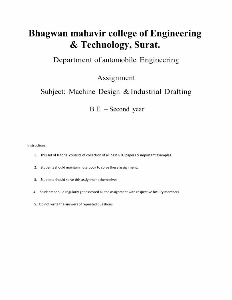
An offset link, fig. has a clear swing of 10 mm. the radius of curvature of curved part is more compare to swing of link. The cross section is shown, where the thickness (t) of link is 26 mm. Find the load corresponding to a maximum fiber stress of 100 N/mm2.
05
DEC 2010
A mild steel link is as shown in Fig. 2, which is subjected to a tensile load of 80 kN. Find the b. The permissible tensile stress is 70 MPa.
07
MAY 2012
6 What is stress concentration and discuss the method to relive the stress concentration with neat sketches.
04 DEC 2010
7 What is factor of safety? Which are the factors to be 03 DEC
considered while selecting the same? 2009
8
A rectangular bar of 40mmX60mm size is subjected to tensile load of 100KN. The factor of safety is 2. Select the suitable material from below given materials. Mild Steel : Permissible tensile stress = 90MPa Cast Iron: Permissible tensile stress = 20MPa
04
DEC 2009
9 Explain stress concentration and methods of reducing it by sketches
03 DEC 2009
10
Explain the following terms with neat sketches. 1) Tensile stress 2) Compressive stress 3) Principle Stress 4) Bearing pressure
04
MAY 2011
11 Classify the different types of load & Explain each In brief.
03 MAY 2011
12 Explain stress concentration & methods of reducing it by sketches
04 MAY 2011
13
A „C‟ frame of the press takes a load of 100 kN at an eccentricity of 250 mm. Calculate the cross-sectional dimensions of the frame, considering the section of frame „I‟ – section with thickness of web and flange being „t‟, depth „6t‟ and width „3t‟. The material of the frame has permissible tensile stress, [σ ] = 100 MPa.
t
09
JAN. 2013
14
Write design procedure for designing a machine element.
04 MAY 2012
Design of fasteners
15
Write types of failure in riveted joint.
02 MARCH
2010
16
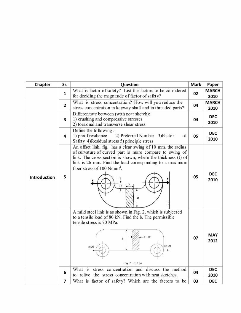
A wall bracket with rectangular cross section is shown in Fig. The depth of the cross-section is twice of the width. The force P acting on the bracket at 300 to the horizontal is 5 KN. The bracket is made gray cast iron FG 200 (Sut = 200N/mm2) and factor of safety = 3.5 Determine the dimensions of the cross section of the bracket
07
MARCH
2010
17
Design a knuckle joint to connect two rods subjected to tensile force of 50 KN. The rods and pin are made of plain carbon steel 30C8. The permissible stresses are σt = σc = 80
07
MARCH 2010
MPa and τ = 40 MPa.
18
Design a knuckle joint to connect two circular mild steel rods which are subjected to a tensile load of 63 kN. The allowable stresses are 80 MPa in tension, 56 Mpa in shear and 80 MPa in crushing.
19 Why cotter is provided with taper? Write the advantages of cotter joint?
04 MARCH
2010
20
Explain the important terminology of riveted joints and find the efficiency of the double riveted lap joints with zig-zag riveting is to be designed for 13 mm thick plates. Assume 80 MPa, 60 MPa and 120 MPa in tension, Shear and crushing respectively. Also calculate pitch of rivets.
07
DEC 2010
21
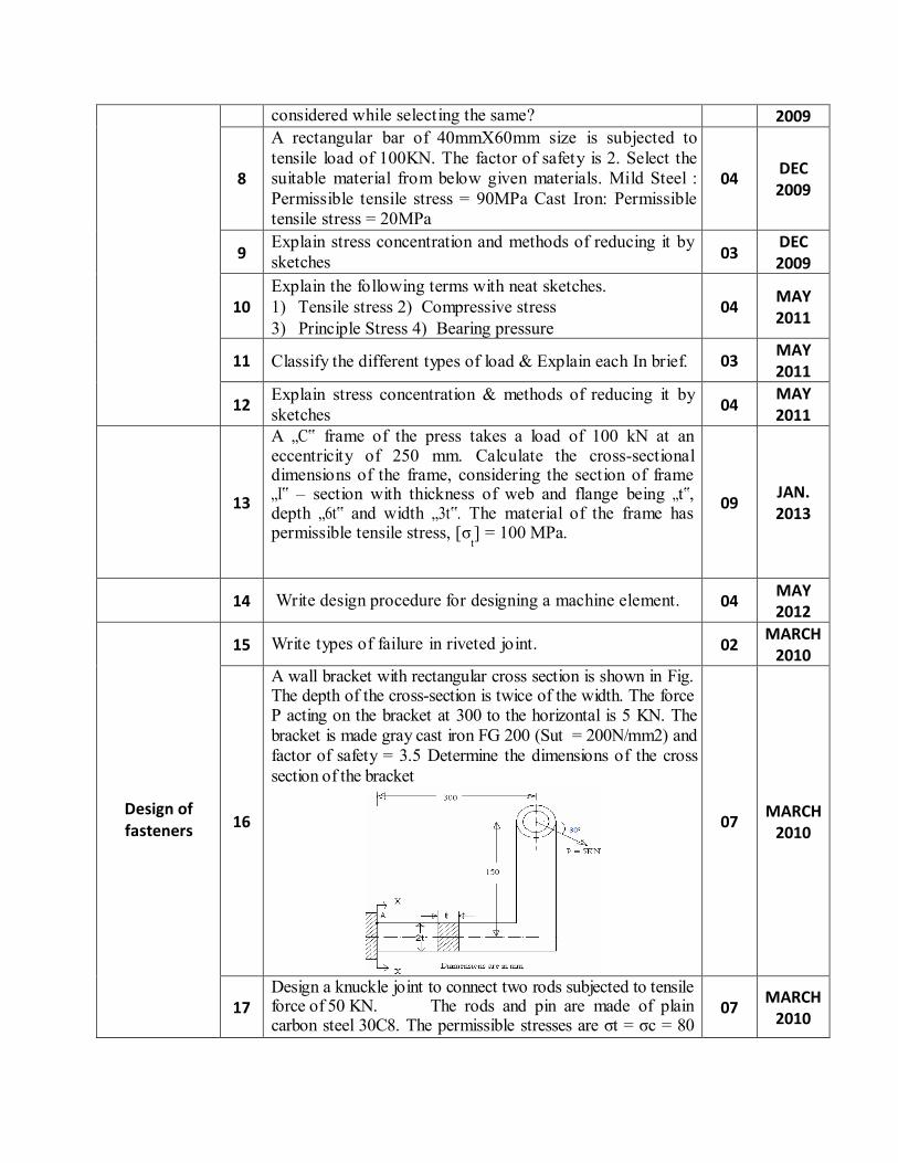
Fig.2 shows 12 mm thick plates loaded by the forces of 100 KN applied eccentrically. Determine the required lengths L1 & L2 of the fillet welds so that they will be equally stressed in shear. Take working stress in shear for side fillets to be equal to 80 N/mm2.
04
DEC 2010
22
A bracket is fillet welded to a structure as shown in Fig. 3, which is subjected to a load of 50 kN. Find the size of weld required if allowable shear stress is not to exceed 75 MPa.
07
MAY 2012
23
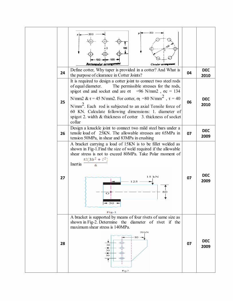
A bracket is to be attached to a wall with the help of six rivets. The different arrangements in which the bracket can be attached to the wall with these rivets are shown in fig. The maximum allowable stress in shear is 60 N/mm2. Determine the way in which the rivets should be arranged so that the design is economical. The bracket is required to support a load of 90 KN with an eccentricity of 200 mm. also determine the diameter of rivet for the selected arrangement.
07
DEC 2010
24 Define cotter, Why taper is provided in a cotter? And What is the purpose of clearance in Cotter Joints?
04 DEC 2010
25
It is required to design a cotter joint to connect two steel rods of equal diameter. The permissible stresses for the rods, spigot end and socket end are σt =96 N/mm2 , σc = 134 N/mm2 & τ = 45 N/mm2. For cotter, σt =80 N/mm2 , τ = 40
N/mm2. Each rod is subjected to an axial Tensile force of 60 KN. Calculate following dimensions: 1. diameter of spigot 2. width & thickness of cotter 3. thickness of socket collar
06
DEC 2010
26
Design a knuckle joint to connect two mild steel bars under a tensile load of 25KN. The allowable stresses are 65MPa in tension 50MPa, in shear and 83MPa in crushing
07
DEC 2009
27
A bracket carrying a load of 15KN is to be fillet welded as shown in Fig-1.Find the size of weld required if the allowable shear stress is not to exceed 80MPa. Take Polar moment of
Inertia
07
DEC 2009
28
A bracket is supported by means of four rivets of same size as shown in Fig-2. Determine the diameter of rivet if the maximum shear stress is 140MPa.
07
DEC 2009
29
Explain the design process for socket and spigot cotter joint
07 DEC 2009
30 Enlist different types of cotter joint & explain design procedure of any one.
07 MAY 2011
31
A Knuckle joint is required to sustain a tensile load of 30 kN. Design the joint, if the permissible stresses are σt = 55 Mpa , τ = 42 Mpa , σc =70 Mpa.
07
MAY 2011
32 Explain various failures of riveted joints.
04 MAY 2011
33
Explain the following terms related to riveted joints. 1) Pitch 3) Margin 2) Diagonal pitch
03
MAY 2011
34
Design a double riveted butt joint with two cover plates for the longitudinal seam of a boiler shell 1.5 m in diameter subjected to a steam pressure of 0.95 N/mm2. Assume joint efficiency as 75%, allowable tensile stress in the plate 90 Mpa, Compressive stress 140 Mpa & shear stress in the rivet 56 Mpa.
07
MAY 2011
35
An eccentrically loaded lap riveted joint is to be designed for a steel bracket as shown in fig.-1. The bracket plate is 25 mm thick. All rivets are to be of same size, load on the bracket P = 50 kN, rivet spacing c = 100 mm, load arm e = 400 mm, permissible shear stress is 64 Mpa, and crushing stress is 120 Mpa. Determine the size of the rivets to be used for the joint.
07
MAY 2011
36
State the types of welded joints & mention the stresses produced in welds in each of joints and explain the general design procedure to design the welded joints.
07
MAY 2011
37
Write design procedure for design of a socket and spigot joint, which may be subjected to an axial load. Write the design equations for different failure criteria. Draw sketches for the same.
07
MAY 2012
38
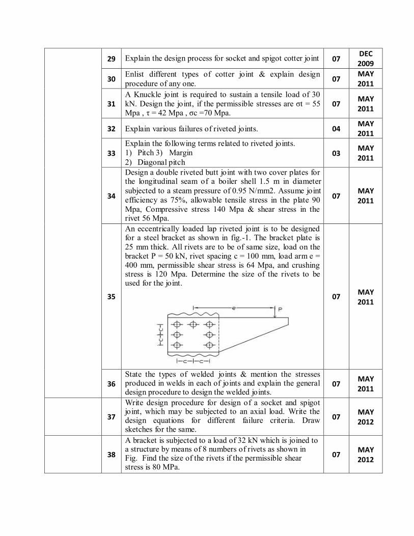
A bracket is subjected to a load of 32 kN which is joined to a structure by means of 8 numbers of rivets as shown in Fig. Find the size of the rivets if the permissible shear stress is 80 MPa.
07
MAY 2012
39
Design and draw a turnbuckle for a capacity of 40 kN, which is used for adjusting tension in a v-belt drive of a machine tool. The permissible stresses for rods and nut are 80 MPa in tension, 50 MPa in shear and 80 MPa in crushing.
07
MAY 2012
40
What do you mean by eccentric loaded welded joint?
Write the detail design procedure for designing such a joint.
07
JAN. 2013
41
Explain the important terminology of riveted joints and find the efficiency ofthe double riveted lap joints with zig-zag riveting is to be designed for 13 mm thick plates. Assume 80 MPa., 60 MPa and 120 MPa in tension, Shear and crushing respectively. Also calculate pitch of rivets.
07
JAN. 2013
42
Draw neat sketch of Gib & cotter joint showing all the parts.
07
JAN. 2013
43
It is required to design a cotter joint to connect two steel rods of equal diameter. The permissible stresses for the rods, spigot end and
2 2 socket end are σ =96 N/mm , σ = 134 N/mm & τ = 45
t c 2
N/mm . For cotter,
2 2 σ =80 N/mm , τ = 40 N/mm . Each rod is subjected to
t an axial Tensile force of 80 KN. Calculate following dimensions: 1. Diameter of spigot 2. Width & thickness of cotter 3. Thickness of socket collar
07
JAN. 2013
Design of Shafts & Keys
44
What is critical speed of shaft?
02 MARCH
2010
45
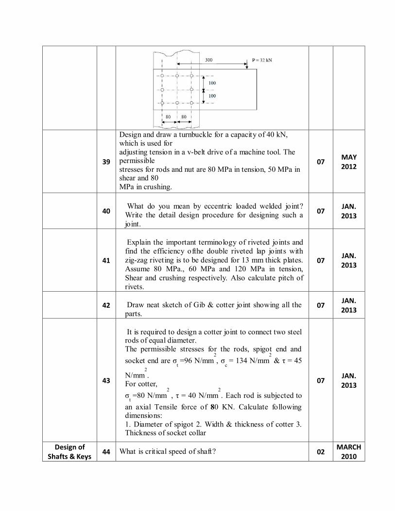
A shaft of rectangular cross-section is welded to a support by means of fillet welds, as shown in Fig.. Determine the size of the welds, if the permissible shear stress in the weld is limited to 75 N/mm2.
07
MARCH
2010
46
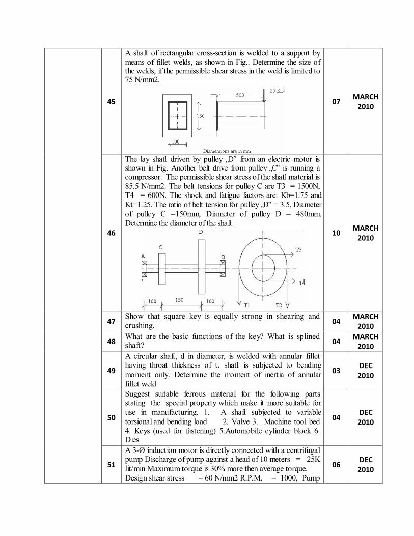
The lay shaft driven by pulley „D‟ from an electric motor is shown in Fig. Another belt drive from pulley „C‟ is running a compressor. The permissible shear stress of the shaft material is 85.5 N/mm2. The belt tensions for pulley C are T3 = 1500N, T4 = 600N. The shock and fatigue factors are: Kb=1.75 and Kt=1.25. The ratio of belt tension for pulley „D‟ = 3.5, Diameter of pulley C =150mm, Diameter of pulley D = 480mm. Determine the diameter of the shaft.
10
MARCH
2010
47 Show that square key is equally strong in shearing and crushing.
04 MARCH
2010
48 What are the basic functions of the key? What is splined shaft?
04 MARCH
2010
49
A circular shaft, d in diameter, is welded with annular fillet having throat thickness of t. shaft is subjected to bending moment only. Determine the moment of inertia of annular fillet weld.
03
DEC 2010
50
Suggest suitable ferrous material for the following parts stating the special property which make it more suitable for use in manufacturing. 1. A shaft subjected to variable torsional and bending load 2. Valve 3. Machine tool bed 4. Keys (used for fastening) 5.Automobile cylinder block 6. Dies
04
DEC 2010
51
A 3-Ø induction motor is directly connected with a centrifugal pump Discharge of pump against a head of 10 meters = 25K lit/min Maximum torque is 30% more then average torque. Design shear stress = 60 N/mm2 R.P.M. = 1000, Pump
06
DEC 2010
efficiency = 85% Design the shaft of electric motor, neglecting weight of shaft & coupling.
52 What is ASME code for shaft design?
02 DEC 2010
53
Determine the diameter below which the angle of twist of a shaft and not the maximum stress is the controlling factor in design of solid shaft in torsion. The allowable shear stress is 56 MPa and the maximum allowable twist is ¼ degree Per meter. Take G = 84 MPa.
06
DEC 2010
54
Compare the weight, strength and rigidity of a hollow shaft of same external diameter as that of solid shafts, both the shafts are made of same material. Assume that diameter ratio for the hollow shaft is di/do = 0.6
06
DEC 2010
55
Explain different types of keys with its applications
07 DEC 2009
56
Design a shaft to transmit power from an electric motor to a lathe head stock through a pulley by means of a belt drive. The pulley weighs 200N and is located at 300mm from the centre of the bearing. The diameter of the pulley is 200mm and the maximum power transmitted is 1KW at 120RPM. The angle of lap of the belt is 180 degree and coefficient of friction between the belt and the pulley is 0.3. The shock and fatigue factors for bending and twisting are 1.5 and 2.0 respectively. The allowable shear stress in the shaft may be taken as 35MPa.
07
DEC 2009
57 State & Explain the various criteria on which shaft are designed?
04 MAY 2011
58
A shaft transmits 75 KW power at 300 rpm load is gradually Applied. It is also subjected to B.M. of 500 N- M, shear stress in shaft material should not exceed 40 N/mm2. Shaft must not twist more than 2° per meter length. Modulus of rigidity of shaft material is 0.8×10⁵ N/mm2. Find the diameter of solid shaft. If the shaft is chosen is hollow with inside to outside diameter ratio = 0.5, Find the size of the hollow shaft. What is the percentage saving in material by using hollow shaft instead of solid shaft?
10
MAY 2011
59
Differentiate in between rigid and flexible coupling.
02 MARCH
2010
60
Design a protective type cast iron flange coupling for a shaft transmitting 15 KW power at a speed of 720 rpm. The permissible stresses are: For the shafts, keys, and bolts material , Permissible tensile stress (σt) = 133.33 Permissible compressive stress (σc) = 200 MPa Permissible shear stress (τ ) = 66.67 MPa
10
MARCH
2010
For flanges material, Permissible shear stress (τ ) = 16.67 MPa The keys have square cross-section.
61
Explain with neat sketch, design procedure of coupler.
04 DEC 2010
62
Discuss the effect of bearing pressure intensity & clearance provided between two faces of couplings in bushed pin type flexible coupling.
04
DEC 2010
63
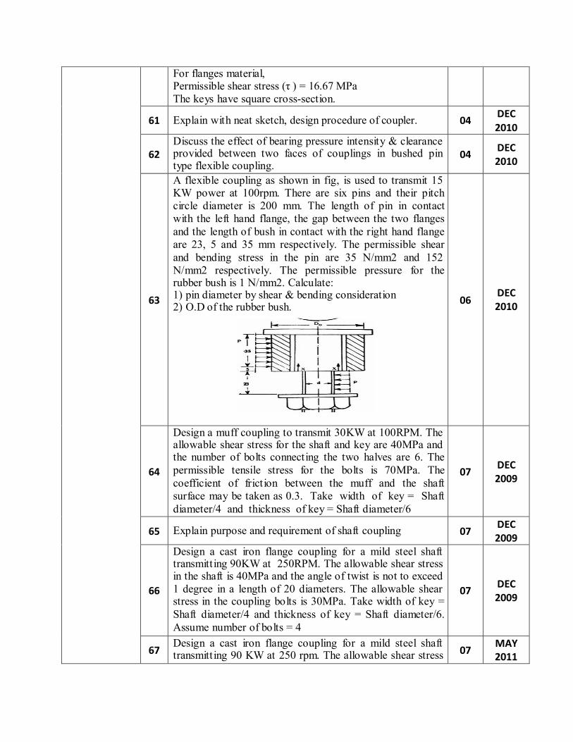
A flexible coupling as shown in fig, is used to transmit 15 KW power at 100rpm. There are six pins and their pitch circle diameter is 200 mm. The length of pin in contact with the left hand flange, the gap between the two flanges and the length of bush in contact with the right hand flange are 23, 5 and 35 mm respectively. The permissible shear and bending stress in the pin are 35 N/mm2 and 152 N/mm2 respectively. The permissible pressure for the rubber bush is 1 N/mm2. Calculate: 1) pin diameter by shear & bending consideration 2) O.D of the rubber bush.
06
DEC 2010
64
Design a muff coupling to transmit 30KW at 100RPM. The allowable shear stress for the shaft and key are 40MPa and the number of bolts connecting the two halves are 6. The permissible tensile stress for the bolts is 70MPa. The coefficient of friction between the muff and the shaft surface may be taken as 0.3. Take width of key = Shaft diameter/4 and thickness of key = Shaft diameter/6
07
DEC 2009
65
Explain purpose and requirement of shaft coupling
07 DEC 2009
66
Design a cast iron flange coupling for a mild steel shaft transmitting 90KW at 250RPM. The allowable shear stress in the shaft is 40MPa and the angle of twist is not to exceed 1 degree in a length of 20 diameters. The allowable shear stress in the coupling bolts is 30MPa. Take width of key = Shaft diameter/4 and thickness of key = Shaft diameter/6. Assume number of bolts = 4
07
DEC 2009
67 Design a cast iron flange coupling for a mild steel shaft transmitting 90 KW at 250 rpm. The allowable shear stress
07 MAY 2011
in the shaft is 40 Mpa and the angle of twist is not to exceed 1 degree in a length of 20 diameters. The allowable shear stress in the coupling bolts is 30 Mpa. Take width of key = shaft diameter/4 & thickness of key = shaft diameter/6. Assume no. of bolts = 4.
68
Explain purpose & requirement of shaft coupling.
03 MAY 2011
69
State the difference between shaft, axle and spindle.
03 JAN. 2013
70
“Square key is stronger against crushing than
rectangular key”. Justify the statement.
05
JAN. 2013
71
Design a muff coupling to transmit 30 kW at 100 rpm. The allowable shear stress for the shaft and key is 40 MPa and the number of bolts connecting the two halves are 6. The permissible tensile stress for the bolts is 70 MPa. The coefficient of friction between the muff and the shaft surface may be taken as 0.3. Take width of key = Shaft diameter/4 and thickness of key = Shaft diameter/6.
07
JAN. 2013
72
A line shaft is driven by means of a motor placed
vertically below it. The pulley on the line shaft is 1.5 meter in diameter and has belt tensions 5.4 kN and 1.8 kN on the tight side and slack side of the belt respectively. Both these tensions may be assumed to be vertical. If the pulley be overhang fro m the shaft, the distance of the centre line of the pulley from the centre line of the bearing being 400 mm, find the diameter of the shaft. Assuming maximum allowable shear stress of 42 MPa.
10
JAN. 2013
73
Draw a neat sketch of a protected type flanged coupling and write the design procedure with the design equations for different failure criteria.
07
MAY 2012
74
A 600 mm diameter pulley transmits 16 kW power at a speed of 400 rpm. Pulley is cantilever at a distance of 200 mm from the nearest bearing. The weight of the pulley is 1500 N. It is driven by a horizontal belt drive. The co- efficient of friction between belt and pulley is 0.3 and the angle of lap 1800. Take the fatigue and shock factors as Kb = 2.0 and Ks = 1.5. Determine the shaft diameter.
07
MAY 2012
75
Explain different types of keys with its applications.
07 MAY 2012
76 Design a cast iron split muff coupling to transmit a power of 10 kW at 250 rpm. Consider an overload of 25%. The
07 MAY 2012
allowable shear stress in the shaft and key is 36 MPa and for the muff 16 MPa. Take the co-efficient of friction 0.3 and the tensile strength of the high tensile bolts 150 MPa.
77
A circular shaft, 75 mm in diameter, is welded to the
support by means of a circumferential fillet weld. It is subjected to a torsional moment of 3000 N-m. Determine the size of weld, if the maximum shear stress
2 in the weld is not to exceed 70 N/mm .
07
JAN. 2013
Power screws
78
What is self-locking and over-hauling of power screw? Why the efficiency of self-locking square threaded screw is less than 50%?
06
MARCH 2010
79
A triple threaded power screw, used in a screw jack, has a nominal diameter of 50 mm and a pitch of 8 mm. The threads are square and the length of nut is 48 mm. The screw jack is used to lift a load of 7.5 KN. The coefficient of friction at the threads is 0.12 and collar friction is negligible. Calculate: (i) the principal shear stress in the screw body, (ii) the transverse shear stresses in the screw and the nut, (iii) the unit bearing pressure. State whether the screw is self-locking or not.
10
MARCH
2010
80 What do you understand by self locking screw? Explain the condition for self locking.
02 DEC 2010
81
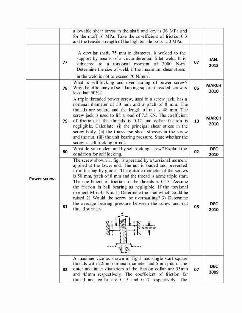
The screw shown in fig. is operated by a torsional moment applied at the lower end. The nut is loaded and prevented from turning by guides. The outside diameter of the screws is 50 mm, pitch of 8 mm and the thread is acme triple start. The coefficient of friction of the threads is 0.15. Assume the friction in ball bearing as negligible. If the torsional moment M is 45 Nm. 1) Determine the load which could be raised 2) Would the screw be overhauling? 3) Determine the average bearing pressure between the screw and nut thread surfaces.
08
DEC 2010
82
A machine vice as shown in Fig-3 has single start square threads with 22mm nominal diameter and 5mm pitch. The outer and inner diameters of the friction collar are 55mm and 45mm respectively. The coefficient of friction for thread and collar are 0.15 and 0.17 respectively. The
07
DEC 2009
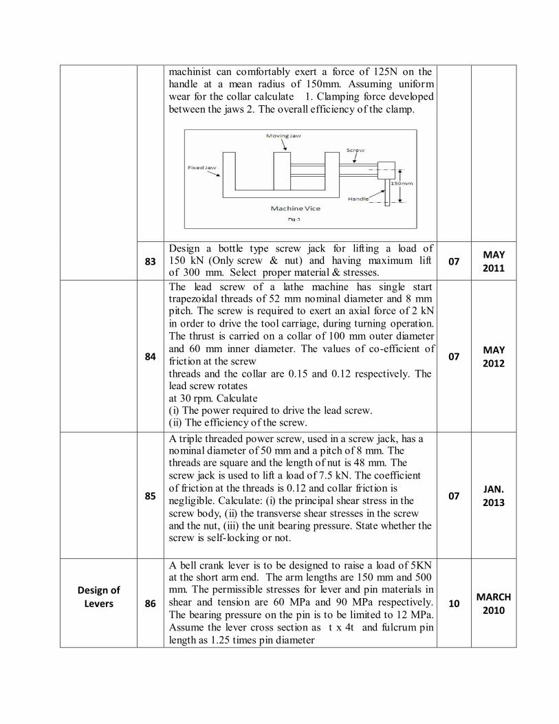
machinist can comfortably exert a force of 125N on the handle at a mean radius of 150mm. Assuming uniform wear for the collar calculate 1. Clamping force developed between the jaws 2. The overall efficiency of the clamp.
83
Design a bottle type screw jack for lifting a load of 150 kN (Only screw & nut) and having maximum lift of 300 mm. Select proper material & stresses.
07
MAY 2011
84
The lead screw of a lathe machine has single start trapezoidal threads of 52 mm nominal diameter and 8 mm pitch. The screw is required to exert an axial force of 2 kN in order to drive the tool carriage, during turning operation. The thrust is carried on a collar of 100 mm outer diameter and 60 mm inner diameter. The values of co-efficient of friction at the screw threads and the collar are 0.15 and 0.12 respectively. The lead screw rotates at 30 rpm. Calculate (i) The power required to drive the lead screw. (ii) The efficiency of the screw.
07
MAY 2012
85
A triple threaded power screw, used in a screw jack, has a nominal diameter of 50 mm and a pitch of 8 mm. The threads are square and the length of nut is 48 mm. The screw jack is used to lift a load of 7.5 kN. The coefficient of friction at the threads is 0.12 and collar friction is negligible. Calculate: (i) the principal shear stress in the screw body, (ii) the transverse shear stresses in the screw and the nut, (iii) the unit bearing pressure. State whether the screw is self-locking or not.
07
JAN. 2013
Design of Levers
86
A bell crank lever is to be designed to raise a load of 5KN at the short arm end. The arm lengths are 150 mm and 500 mm. The permissible stresses for lever and pin materials in shear and tension are 60 MPa and 90 MPa respectively. The bearing pressure on the pin is to be limited to 12 MPa. Assume the lever cross section as t x 4t and fulcrum pin length as 1.25 times pin diameter
10
MARCH
2010
87
Determine the maximum and the minimum normal stress for a 75 mm diameter rod, supported at one end as a cantilever which is subjected to an axial compressive load of 15 KN and a tensional moment of 1KNm.
04
DEC 2010
88
Why the levers are generally made tapers?
02 DEC 2010
89
A lever loaded safety valve is 70 mm in diameter and is to be designed for a boiler to blow off at a pressure of 1N/mm2. design a suitable mild steel lever of rectangular cross section using the following permissible stresses: Tensile stress- 70 N/mm2, Shear stress- 50 N/mm2, Bearing pressure - 25 N/mm2 The pin is made of mild steel. The distance from the fulcrum to the weight of the lever is 880 mm and the distance between the fulcrum and pin connecting the valve spindle links to the lever is 80 mm.
08
DEC 2010
90
A lever loaded safety valve is 70mm in diameter and is to be designed for a boiler to blow off at pressure of 1N/mm2
gauge. Design a suitable mild steel lever of rectangular cross section. For mild steel: Permissible tensile stress = 70MPa, Shear stress = 50MPa, Bearing pressure intensity = 25N/mm2 The pin is also made of mild steel. The distance from the fulcrum to the weight of the lever is 880mm and the distance between the fulcrum and pin connecting the valve spindle links to the lever is 80mm.
07
DEC 2009
91
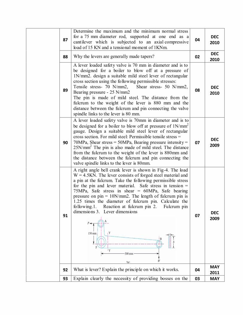
A right angle bell crank lever is shown in Fig-4. The load W = 4.5KN. The lever consists of forged steel material and a pin at the fulcrum. Take the following permissible stress for the pin and lever material. Safe stress in tension = 75MPa, Safe stress in shear = 60MPa, Safe bearing pressure on pin = 10N/mm2. The length of fulcrum pin is 1.25 times the diameter of fulcrum pin. Calculate the following.1. Reaction at fulcrum pin 2. Fulcrum pin dimensions 3. Lever dimensions
07
DEC 2009
92
What is lever? Explain the principle on which it works.
04 MAY 2011
93 Explain clearly the necessity of providing bosses on the 03 MAY
lever at pin locations. 2011
94
Design a right angled bell crank lever having one arm 500 mm & the other 150 mm long. The load of 5 kN is to be raised acting on a pin at the end of 500 mm arm & the effort is applied at the end of 150 mm arm. The lever consists of steel forgings, turning on a point at the fulcrum. The permissible stresses for the pin & lever are 84 Mpa in tension & compression & 70 Mpa in shear, the bearing pressure on the pin is not to exceed 10 N/mm2.
07
MAY 2011
95
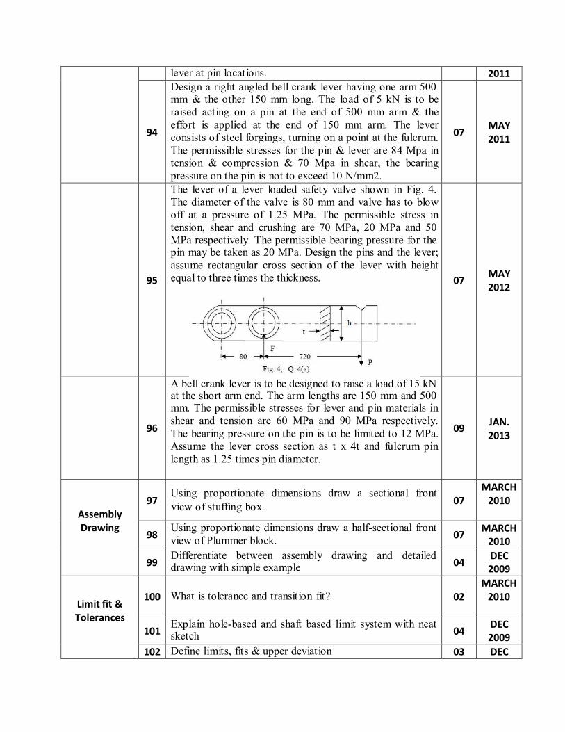
The lever of a lever loaded safety valve shown in Fig. 4. The diameter of the valve is 80 mm and valve has to blow off at a pressure of 1.25 MPa. The permissible stress in tension, shear and crushing are 70 MPa, 20 MPa and 50 MPa respectively. The permissible bearing pressure for the pin may be taken as 20 MPa. Design the pins and the lever; assume rectangular cross section of the lever with height equal to three times the thickness.
07
MAY 2012
96
A bell crank lever is to be designed to raise a load of 15 kN at the short arm end. The arm lengths are 150 mm and 500 mm. The permissible stresses for lever and pin materials in shear and tension are 60 MPa and 90 MPa respectively. The bearing pressure on the pin is to be limited to 12 MPa. Assume the lever cross section as t x 4t and fulcrum pin length as 1.25 times pin diameter.
09
JAN. 2013
Assembly Drawing
97
Using proportionate dimensions draw a sectional front
07 MARCH
2010
98 Using proportionate dimensions draw a half-sectional front view of Plummer block.
07 MARCH
2010
99 Differentiate between assembly drawing and detailed drawing with simple example
04 DEC 2009
Limit fit & Tolerances
100
What is tolerance and transition fit?
02
MARCH 2010
101 Explain hole-based and shaft based limit system with neat sketch
04 DEC 2009
102 Define limits, fits & upper deviation 03 DEC
view of stuffing box.
2009 103
Draw the generalized surface roughness symbol showing position of different information on it
04
DEC 2009
104 Give symbol for straightness, flatness, perpendicularity, cylindricity, symmetry and angularity
03 DEC 2009
105
Explain surface roughness symbols & importance of it.
04 MAY 2011
106
Differentiate between assembly drawing & detail drawing.
03 MAY 2011
107 Differentiate between hole basis system & shaft basis system with necessary sketches.
04 MAY 2011
108
Draw the generalized surface roughness symbol showing position of all information on it.
04
MAY 2012
109
Explain the machining symbol with all parameter.
03 MAY 2012
110 Give symbol for straightness, flatness, perpendicularity, cylindricity, symmetry & angularity.
03 MAY 2011
111
Define limits, fits, and tolerance.
03 MAY 2012
112
Explain “Shaft base system” and “Hole base system” with necessary examples..
07
JAN. 2013
AutoCAD
113 Write the use of the following commands (1) Fillet (2) Explode (3) Scale (4) Array (5) Trim.
05 MARCH
2010
114 Write the sequence of AutoCAD commands to be used to draw FV and TV of a hexagonal nut M20x2.
05 MARCH
2010
115
Explain any four editing commands of AUTOCAD.
04 DEC 2010
116
Explain circle, arc, rectangle and polygon commands for Auto CAD drawing. With suitable example explain use of mirror command
07
DEC 2009
117
Explain following AutoCAD command with example. 1) copy 2) Mirror 3) Poly line 4) Trim 5) Extend 6) Hatch 7) line
07
MAY 2011


![Bhagwan Mahavir Swami[1]](https://img.pdfslide.us/doc/110x75/552244c04a79595d5e8b4812/bhagwan-mahavir-swami1.jpg)