Embed Size (px)
Citation preview
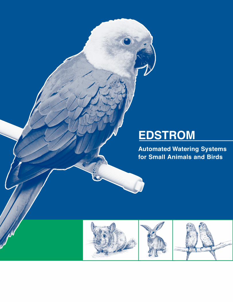
EDSTROM Automated Watering Systemsfor Small Animals and Birds
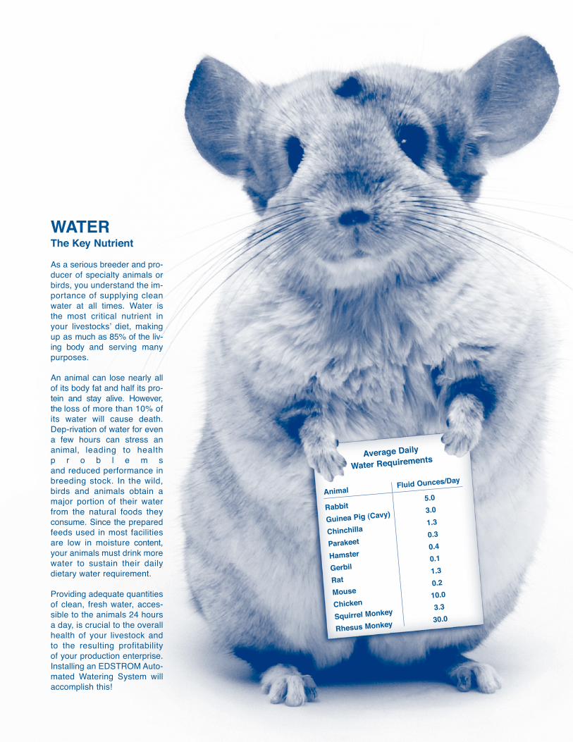
As a serious breeder and pro-ducer of specialty animals orbirds, you understand the im-portance of supplying cleanwater at all times. Water isthe most critical nutrient inyour livestocks’ diet, makingup as much as 85% of the liv-ing body and serving manypurposes.
An animal can lose nearly all of its body fat and half its pro-tein and stay alive. However,the loss of more than 10% ofits water will cause death.Dep-rivation of water for evena few hours can stress ananimal, leading to healthp r o b l e m sand reduced performance inbreeding stock. In the wild,birds and animals obtain amajor portion of their waterfrom the natural foods theyconsume. Since the preparedfeeds used in most facilitiesare low in moisture content,your animals must drink morewater to sustain their dailydietary water requirement.
Providing adequate quantitiesof clean, fresh water, acces-sible to the animals 24 hoursa day, is crucial to the overallhealth of your livestock andto the resulting profitabilityof your production enterprise.Installing an EDSTROM Auto-mated Watering System willaccomplish this!
WATERThe Key Nutrient
Average Daily
Water Requirements
Animal
Rabbit
Guinea Pig (Cavy)
Chinchilla
Parakeet
Hamster
Gerbil
Rat
Mouse
Chicken
Squirrel Monkey
Rhesus Monkey
5.0
3.0
1.3
0.3
0.4
0.1
1.3
0.2
10.0
3.3
30.0
Fluid Ounces/Day
How to Succeed with EDSTROM Automated Watering Equipment
The EDSTROM Drinking ValveVari-Flo Drinking ValvesOriginal Drinking Valves
Look Inside the Valve
Distribution PipingFlex-Tube SystemRigid Piping System
Water Supply ComponentsPressure Regulator MethodsGravity Feed Methods
Designing an Automated Watering SystemInstallation Methods - Flex-Tube SystemsInstallation Methods - Rigid PVC Pipe SystemsInstallation Methods - Combination Systems
Systems Guidelines for Startup
Operation and Maintenance
Specialty Waterers
Exotic Bird Watering
Cup Waterers for Poultry
Trouble Shooting Guide
Parts ListDrinking ValvesSpecialty WaterersWater Supply ComponentsFlex-Tube System ComponentsRigid PVC Pipe ComponentsDrinking Valve Repair Parts
EDSTROM Kits
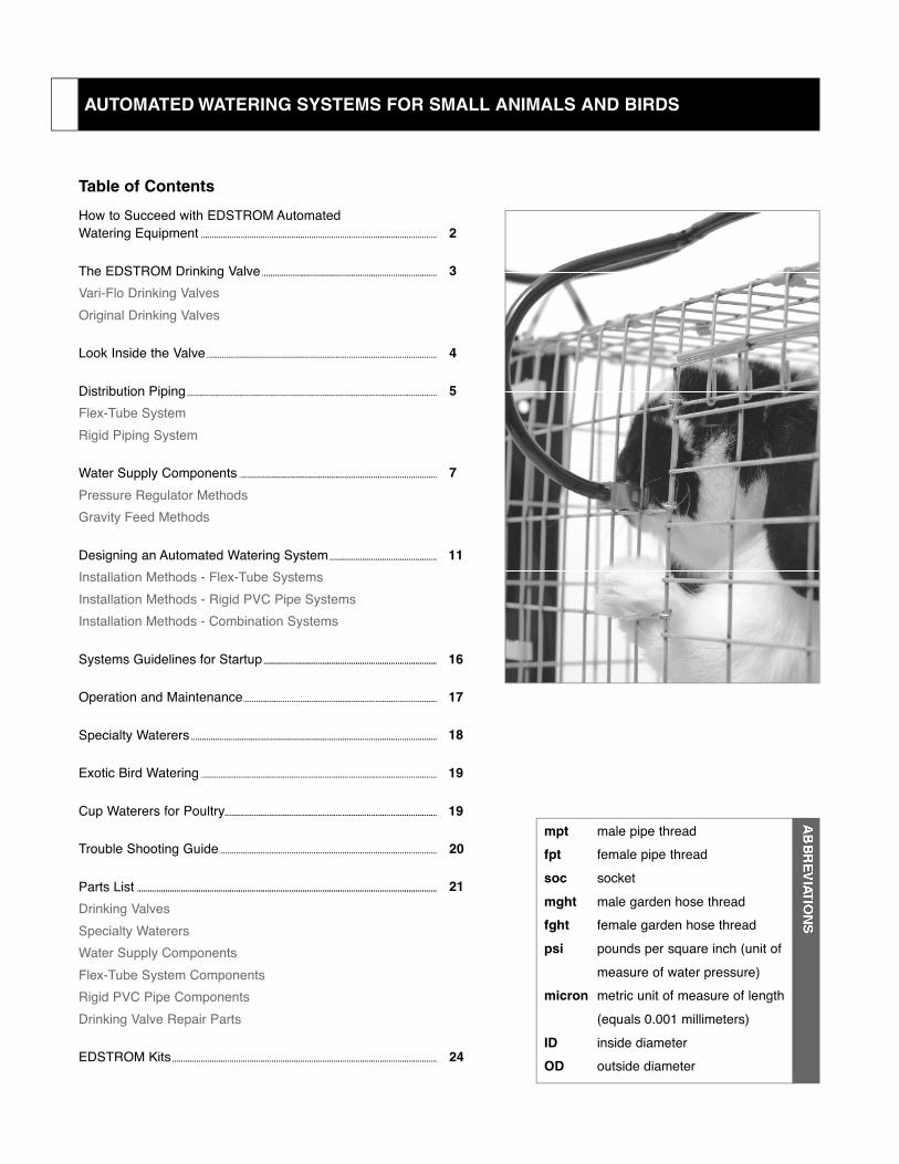
Table of Contents
mpt male pipe thread fpt female pipe thread soc socketmght male garden hose threadfght female garden hose threadpsi pounds per square inch (unit of
measure of water pressure)micron metric unit of measure of length
(equals 0.001 millimeters)ID inside diameterOD outside diameter
AUTOMATED WATERING SYSTEMS FOR SMALL ANIMALS AND BIRDS
2
3
4
5
7
11
16
17
18
19
19
20
21
24
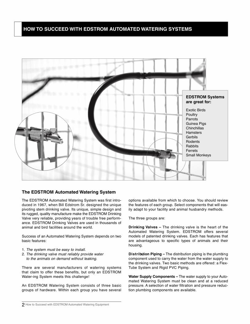
The EDSTROM Automated Watering System was first intro-duced in 1967, when Bill Edstrom Sr. designed the uniquepivoting stem drinking valve. Its unique, simple design andits rugged, quality manufacture make the EDSTROM DrinkingValve very reliable, providing years of trouble free perform-ance. EDSTROM Drinking Valves are used in thousands ofanimal and bird facilities around the world.
Success of an Automated Watering System depends on twobasic features:
1 . The system must be easy to install.2 . The drinking valve must reliably provide water
to the animals on demand without leaking.
There are several manufacturers of watering systemsthat claim to offer these benefits, but only an EDSTROMWater-ing System meets this challenge!
An EDSTROM Watering System consists of three basicgroups of hardware. Within each group you have several
options available from which to choose. You should reviewthe features of each group. Select components that will eas-ily adapt to your facility and animal husbandry methods.
The three groups are:
Drinking Valves – The drinking valve is the heart of the Automated Watering System. EDSTROM offers severalm o dels of patented drinking valves. Each has features thatare advantageous to specific types of animals and theirh o u s i n g .
D i s t r i bution Piping – The distribution piping is the plumbi n gcomponent used to carry the water from the water supply tothe drinking valves. Two basic methods are offered: a Flex-Tube System and Rigid PVC Piping.
Water Supply Components – The water supply to your Auto-mated Watering System must be clean and at a reducedpressure. A selection of water filtration and pressure reduc-tion plumbing components are available.
The EDSTROM Automated Watering System
2 How to Succeed with EDSTROM Automated Watering Equipment
HOW TO SUCCEED WITH EDSTROM AUTOMATED WATERING SYSTEMS
EDSTROM Systems
are great for:
Exotic BirdsPoultryParrotsGuinea PigsChinchillasHamstersGerbilsRodentsRabbitsFerretsSmall Monkeys
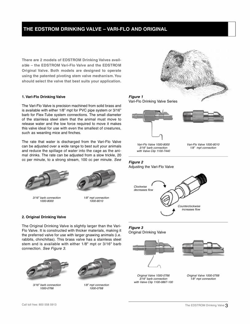
1. Vari-Flo Drinking Valve
The Vari-Flo Valve is precision machined from solid brass andis available with either 1/8” mpt for PVC pipe system or 3/16”barb for Flex-Tube system connections. The small diameterof the stainless steel stem that the animal must move torelease water and the low force required to move it makesthis valve ideal for use with even the smallest of creatures,such as weanling mice and finches.
The rate that water is discharged from the Vari-Flo Va l v ecan be adjusted over a wide range to best suit your animalsand reduce the spillage of water into the cage as the ani-mal drinks. The rate can be adjusted from a slow trickle, 20cc per minute, to a strong stream, 100 cc per minute. See
3/16” barb connection1000-8000
1/8” mpt connection1000-8010
3/16” barb connection1000-0766
1/8” mpt connection1000-0768
Vari-Flo Valve 1000-80003/16” barb connection
with Valve Clip 1100-7440
Vari-Flo Valve 1000-8010 1/8” mpt connection
Figure 1
Vari-Flo Drinking Valve Series
Original Valve 1000-0766 3/16” barb connection
with Valve Clip 1100-0867-100
Original Valve 1000-0768 1/8” mpt connection
Figure 3
Original Drinking Valve
Figure 2
Adjusting the Vari-Flo Valve
There are 2 models of EDSTROM Drinking Valves ava i l -
a ble – the EDSTROM Vari-Flo Valve and the EDSTRO M
Original Va l v e. Both models are designed to operate
using the patented pivoting stem valve mech a n i s m .Yo u
should select the valve that best suits your application.
2. Original Drinking Valve
The Original Drinking Valve is slightly larger than the Va r i -Flo Valve. It is constructed with thicker materials, making itthe preferred valve for use with larger gnawing animals (i.e.rabbits, chinchillas). This brass valve has a stainless steelstem and is available with either 1/8" mpt or 3/16" barbconnection. See Figure 3.
The EDSTROM Drinking Valve 3Call toll free: 800 558 5913
Clockwisedecreases flow
Counterclockwiseincreases flow
THE EDSTROM DRINKING VALVE – VARI-FLO AND ORIGINAL
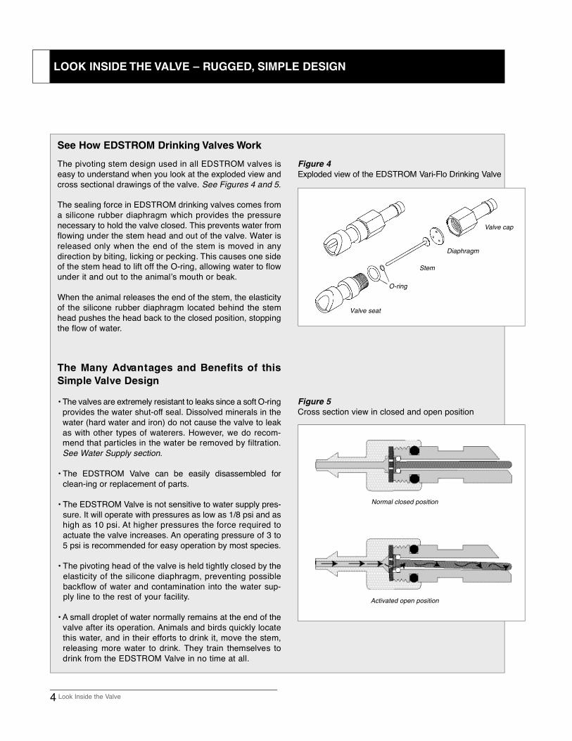
The pivoting stem design used in all EDSTROM valves iseasy to understand when you look at the exploded view andcross sectional drawings of the valve. See Figures 4 and 5.
The sealing force in EDSTROM drinking valves comes froma silicone rubber diaphragm which provides the pressurenecessary to hold the valve closed. This prevents water fromflowing under the stem head and out of the valve. Water isreleased only when the end of the stem is moved in anydirection by biting, licking or pecking. This causes one sideof the stem head to lift off the O-ring, allowing water to flowunder it and out to the animal’s mouth or beak.
When the animal releases the end of the stem, the elasticityof the silicone rubber diaphragm located behind the stemhead pushes the head back to the closed position, stoppingthe flow of water.
The Many Adva n t ages and Benefits of this
Simple Valve Design
• The valves are extremely resistant to leaks since a soft O-ringprovides the water shut-off seal. Dissolved minerals in thewater (hard water and iron) do not cause the valve to leakas with other types of waterers. However, we do recom-mend that particles in the water be removed by filtration.See Water Supply section.
• The EDSTROM Valve can be easily disassembled forclean-ing or replacement of parts.
• The EDSTROM Valve is not sensitive to water supply pres-sure. It will operate with pressures as low as 1/8 psi and ashigh as 10 psi. At higher pressures the force required toactuate the valve increases. An operating pressure of 3 to5 psi is recommended for easy operation by most species.
• The pivoting head of the valve is held tightly closed by the elasticity of the silicone diaphragm, preventing possiblebackflow of water and contamination into the water sup-ply line to the rest of your facility.
• A small droplet of water normally remains at the end of the valve after its operation. Animals and birds quickly locatethis water, and in their efforts to drink it, move the stem,releasing more water to drink. They train themselves todrink from the EDSTROM Valve in no time at all.
Figure 4
Exploded view of the EDSTROM Vari-Flo Drinking Va l v e
Figure 5
Cross section view in closed and open position
Normal closed position
Activated open position
4 Look Inside the Valve
See How EDSTROM Drinking Valves Work
Valve cap
Diaphragm
Stem
O-ring
Valve seat
LOOK INSIDE THE VALVE – RUGGED, SIMPLE DESIGN
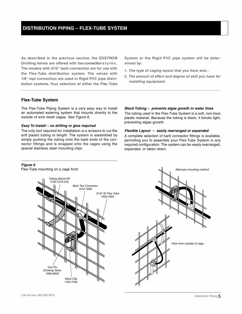
The Flex-Tube Piping System is a very easy way to installan automated watering system that mounts directly to theoutside of wire mesh cages. See Figure 6.
Easy To Install – no drilling or glue required
The only tool required for installation is a scissors to cut thesoft plastic tubing to length. The system is assembled bysimply pushing the tubing onto the barb ends of the con-nector fittings and is snapped onto the cages using thespecial stainless steel mounting clips.
Black Tubing – prevents algae growth in water lines
The tubing used in the Flex-Tube System is a soft, non-toxicplastic material. Because the tubing is black, it blocks light,preventing algae growth.
Flexible Layout – easily rearranged or expanded
A complete selection of barb connector fittings is available,permitting you to assemble your Flex-Tube System in anyrequired configuration. The system can be easily rearranged,expanded, or taken down.
Figure 6
Flex-Tube mounting on a cage front Alternate mounting method
View from outside of cage
Tubing Stand-Off1100-7273-316
Barb Tee Connector1610-1656
3/16” ID Flex-Tube1600-1654
Vari-FloDrinking Valve
1000-8000
Valve Clip1100-7440
As described in the previous section, the EDSTRO M
Drinking Valves are offered with two connection s t y l e s .
The models with 3/16” barb connection are for use with
the Flex - Tube distribution system. The valves with
1 / 8 ” mpt connection are used in Rigid PVC pipe distri-
bution systems. Your selection of either the Flex - Tu b e
System or the Rigid PVC pipe system will be deter-
mined by :
1 . The type of caging layout that you have and...
2 . The amount of effo rt and degree of skill you have for
installing equipment.
Distribution Piping 5
Flex-Tube System
DISTRIBUTION PIPING – FLEX-TUBE SYSTEM
Call toll free: 800 558 5913
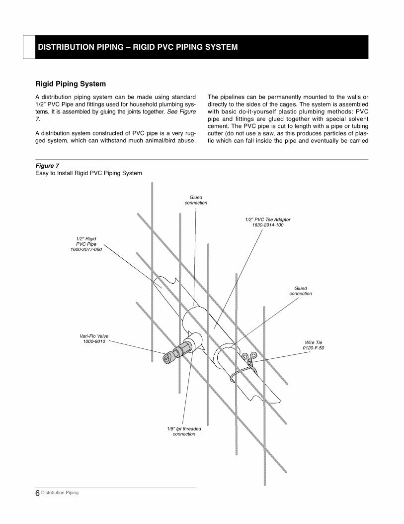
A distribution piping system can be made using standard1/2” PVC Pipe and fittings used for household plumbing sys-tems. It is assembled by gluing the joints together. See Figure7 .
A distribution system constructed of PVC pipe is a very rug-ged system, which can withstand much animal/bird abuse.
The pipelines can be permanently mounted to the walls ordirectly to the sides of the cages. The system is assembledwith basic do-it-yourself plastic plumbing methods: PVCpipe and fittings are glued together with special solventcement. The PVC pipe is cut to length with a pipe or tubingcutter (do not use a saw, as this produces particles of plas-tic which can fall inside the pipe and eventually be carried
Vari-Flo Valve1000-8010
1/8” fpt threadedconnection
Glued connection
1/2” PVC Tee Adaptor1630-2914-100
1/2” Rigid PVC Pipe
1600-2077-060
Wire Tie0120-F-50
Figure 7
Easy to Install Rigid PVC Piping System
Glued connection
6 Distribution Piping
Rigid Piping System
DISTRIBUTION PIPING – RIGID PVC PIPING SYSTEM
Pressure Regulator Method
A convenient and reliable method of providing water at re-duced pressure to your watering system is with a pressurer e g u l a t o r. This device connects directly to your house watersupply and as water flows through, it reduces high waterpressure to the low pressure required for your wateringsystem. The advantage of this method is that it makes yourwatering system fully automated – no gravity supply tanks tomonitor and fill. In addition, because the flow of water isalways confined in the pipeline, there is no chance of con-tamination and there are no open tanks to keep clean.
The pressure regulator offered by EDSTROM Industriesaccurately maintains the outlet pressure over a wide flowhandling range. The unit is tested and preset at the factoryfor an outlet pressure of 3 psi; however, the outlet pressureis adjustable from 3/4 psi to 10 psi.
EDSTROM offers three Pressure Regulator Kits:
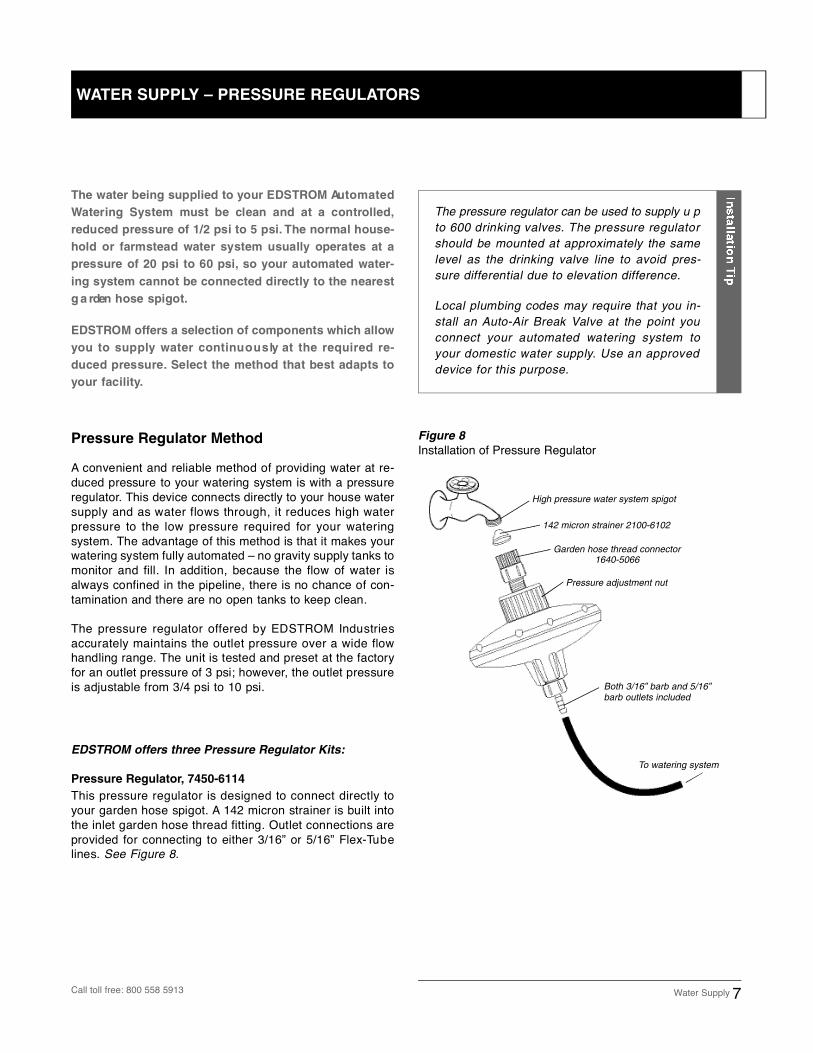
Pressure Regulator, 7450-6114
This pressure regulator is designed to connect directly toyour garden hose spigot. A 142 micron strainer is built intothe inlet garden hose thread fitting. Outlet connections areprovided for connecting to either 3/16” or 5/16” Flex-Tu b elines. See Figure 8.
Figure 8
Installation of Pressure Regulator
High pressure water system spigot
142 micron strainer 2100-6102
Garden hose thread connector1640-5066
Pressure adjustment nut
Both 3/16” barb and 5/16”barb outlets included
To watering system
Water Supply 7
The water being supplied to your EDSTROM Au t o m a t e d
Watering System must be clean and at a contro l l e d ,
reduced pressure of 1/2 psi to 5 psi. The normal house-
hold or farmstead water system usually operates at a
pressure of 20 psi to 60 psi, so your automated water-
ing system cannot be connected directly to the nearest
g a rden hose spigot.
E D S T ROM offe rs a selection of components which allow
you to supply water continu o u s ly at the required re-
duced pressure. Select the method that best adapts to
your facility.
The pressure regulator can be used to supply u pto 600 drinking valves. The pressure regulatorshould be mounted at approximately the samelevel as the drinking valve line to avoid pres-sure differential due to elevation difference.
Local plumbing codes may require that you in-stall an Auto-Air Break Valve at the point youconnect your automated watering system toyour domestic water supply. Use an approveddevice for this purpose.
WATER SUPPLY – PRESSURE REGULATORS
Call toll free: 800 558 5913
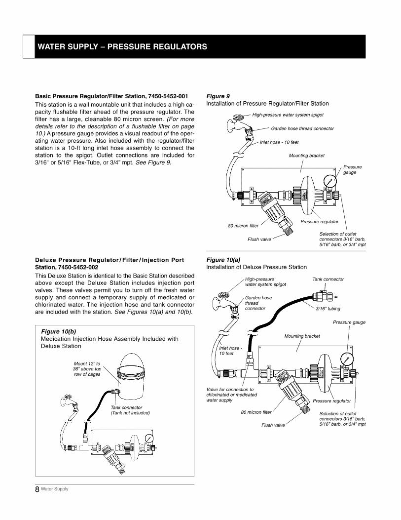
Basic Pressure Regulator/Filter Station, 7450-5452-001
This station is a wall mountable unit that includes a high ca-pacity flushable filter ahead of the pressure regulator. T h efilter has a large, cleanable 80 micron screen. (For moredetails refer to the description of a flushable filter on page10.) A pressure gauge provides a visual readout of the oper-ating water pressure. Also included with the regulator/filterstation is a 10-ft long inlet hose assembly to connect thestation to the spigot. Outlet connections are included for3/16" or 5/16" Flex-Tube, or 3/4” mpt. See Figure 9.
Figure 10(a)
Installation of Deluxe Pressure Station
Garden hose thread connector
Inlet hose - 10 feet
Mounting bracket
Pressure regulator
Selection of outlet connectors 3/16” barb,5/16” barb, or 3/4” mpt
Pressure gauge
Flush valve
80 micron filter
High-pressure water system spigot
Garden hose thread connector
Inlet hose -10 feet
Mounting bracket
Pressure regulator
Selection of outlet connectors 3/16” barb,5/16” barb, or 3/4” mpt
Pressure gauge
Flush valve
80 micron filter
Valve for connection to chlorinated or medicatedwater supply
Mount 12” to36” above toprow of cages
Figure 10(b)
Medication Injection Hose Assembly Included withDeluxe Station
Figure 9
Installation of Pressure Regulator/Filter Station
8 Water Supply
D e l u xe Pressure Regulator / F i l t er / Injection Po rt
Station, 7450-5452-002
This Deluxe Station is identical to the Basic Station describedabove except the Deluxe Station includes injection portvalves. These valves permit you to turn off the fresh watersupply and connect a temporary supply of medicated orchlorinated water. The injection hose and tank connectorare included with the station. See Figures 10(a) and 10(b).
High-pressure water system spigot
Tank connector(Tank not included)
WATER SUPPLY – PRESSURE REGULATORS
3/16” tubing
Tank connector
Gravity Feed Method
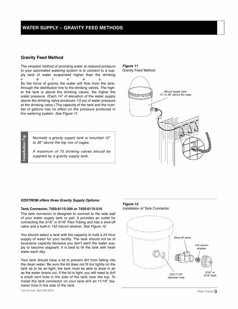
The simplest method of providing water at reduced pressureto your automated watering system is to connect to a sup-ply tank of water suspended higher than the drinkingv a l v e s . By the force of gravity the water will flow from the tank,through the distribution line to the drinking valves. The high-er the tank is above the drinking valves, the higher thewater pressure. (Each 14” of elevation of the water supplyabove the drinking valve produces 1/2 psi of water pressureat the drinking valve.) The capacity of the tank and the num-ber of gallons has no effect on the pressure produced inthe watering system. See Figure 11.
EDSTROM offers three Gravity Supply Options:
Tank Connector, 7450-6115-200 or 7450-6115-516
The tank connector is designed to connect to the side wallof your water supply tank or pail. It provides an outlet forc o nnecting the 3/16” or 5/16” Flex-Tubing and has a shut-offvalve and a built-in 142 micron strainer. See Figure 12.
You should select a tank with the capacity to hold a 24 hoursupply of water for your facility. The tank should not be ofexcessive capacity because you don't want the water sup-ply to become stagnant. It is best to fill the tank with freshwater each day.
Your tank should have a lid to prevent dirt from falling intothe clean water. Be sure the lid does not fit too tightly on thetank as to be air-tight; the tank must be able to draw in airas the water drains out. If the lid is tight, you will need to drilla small vent hole in the side of the tank near the top. Toinstall the tank connector on your tank drill an 11/16” dia-meter hole in the side of the tank.
Mount supply tank 12” to 36” above the cage
Figure 11
Gravity Feed Method
Water Supply 9
Figure 12
Installation of Tank Connector
Shut-off valve
142 micronstrainer
3/16” or5/16” barb
Normally a gravity supply tank is mounted 12”to 36” above the top row of cages.
A maximum of 75 drinking valves should besupplied by a gravity supply tank.
WATER SUPPLY – GRAVITY FEED METHODS
Call toll free: 800 558 5913
Drill 11/16”diameter hole
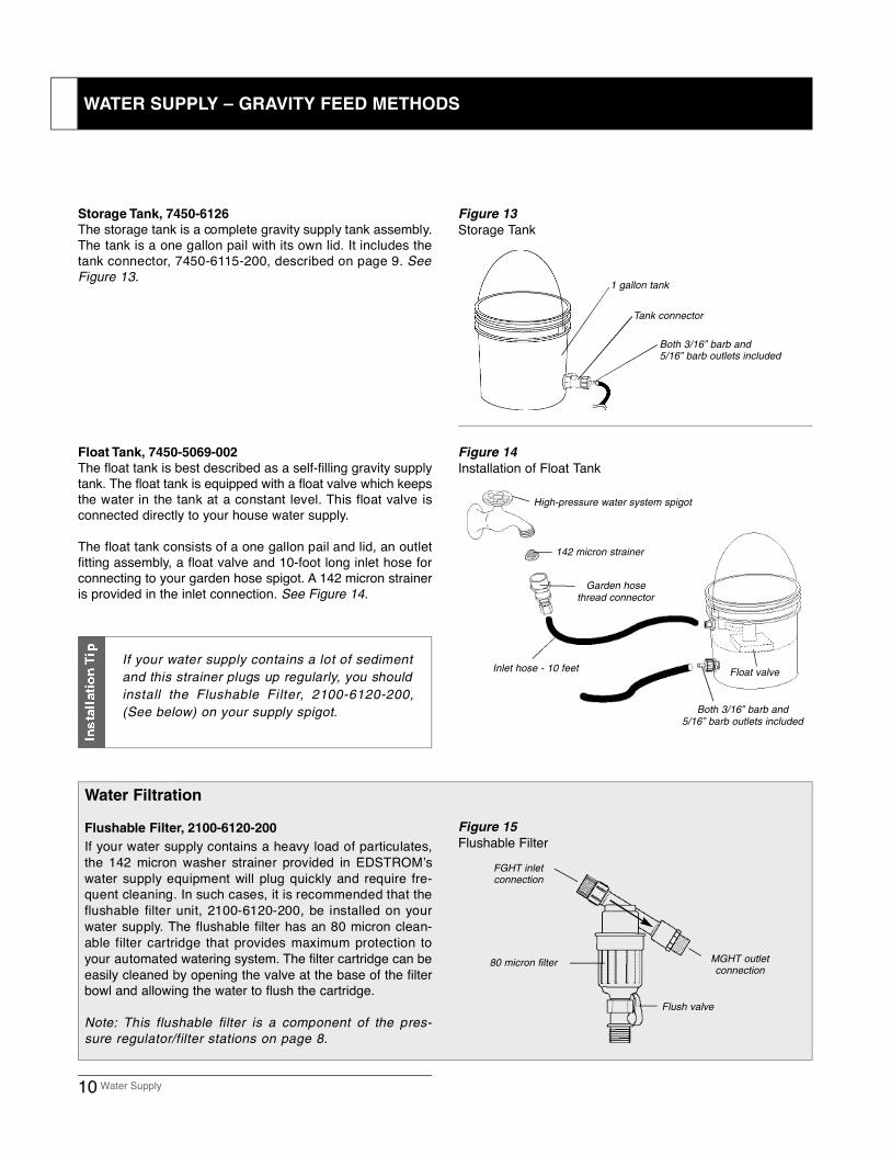
Storage Tank, 7450-6126
The storage tank is a complete gravity supply tank assembly.The tank is a one gallon pail with its own lid. It includes thetank connector, 7450-6115-200, described on page 9. S e eFigure 13.
Figure 13
Storage Tank
1 gallon tank
Tank connector
Both 3/16” barb and 5/16” barb outlets included
High-pressure water system spigot
Garden hosethread connector
Inlet hose - 10 feet
Flush valve
80 micron filter
142 micron strainer
Both 3/16” barb and 5/16” barb outlets included
Float valve
FGHT inletconnection
MGHT outlet connection
Figure 14
Installation of Float Tank
Figure 15
Flushable Filter
10 Water Supply
Water Filtration
Flushable Filter, 2100-6120-200
If your water supply contains a heavy load of particulates,the 142 micron washer strainer provided in EDSTROM’swater supply equipment will plug quickly and require fre-quent cleaning. In such cases, it is recommended that theflushable filter unit, 2100-6120-200, be installed on yourwater supply. The flushable filter has an 80 micron clean-able filter cartridge that provides maximum protection toyour automated watering system. The filter cartridge can beeasily cleaned by opening the valve at the base of the filterbowl and allowing the water to flush the cartridge.
Note: This flushable filter is a component of the pres-sure regulator/filter stations on page 8.
If your water supply contains a lot of sedimentand this strainer plugs up regularly, you shouldinstall the Flushable Filter, 2100-6120-200,(See below) on your supply spigot.
Float Tank, 7450-5069-002
The float tank is best described as a self-filling gravity supplytank. The float tank is equipped with a float valve which keepsthe water in the tank at a constant level. This float valve isconnected directly to your house water supply.
The float tank consists of a one gallon pail and lid, an outletfitting assembly, a float valve and 10-foot long inlet hose forconnecting to your garden hose spigot. A 142 micron straineris provided in the inlet connection. See Figure 14.
WATER SUPPLY – GRAVITY FEED METHODS
To determine the components that you will need to install anAutomated Watering System in your animal facility, youshould first review the installation methods below and theoptions detailed on pages 12 to 15. After deciding whichbasic installation method will work in your facility, you mustselect and determine the quantity of all components required.
You may find it helpful to draw a layout of your facility andcage arrangement to scale on graph paper. This will make iteasier to calculate the length of the distribution piping lines,as well as the quantity of fittings and drinking valves.
As you prepare your list, be sure you select the properc o mponents from each of the basic groups in a watering sys-t e m :
Drinking Valve
Distribution Piping
Designing an Automated Watering System 11
Whether you select to set up your automated watering sys-tem using the Flex-Tube Piping System, Rigid PVC PipingSystem or a combination of both, there are several basicsystem design principles you need to consider as you doyour layout and prepare your parts list:
1. Place the drinking valves on the side of the cage at a loca-tion and height that the animal can easily reach. The drink-ing valve should not be located in the nesting area, norshould it be located immediately above the feeding sta-t i o n .
2. Run lateral lines as near horizontal as possible; avoidg o i n g up and over an obstacle and back to horizontal. The rea-son for this is to avoid high points in the line where airpockets can form, which cannot be easily flushed out.
Lateral lines are the piping lines that run the length of thecages and to which the drinking valves are connected.Header lines are used to interconnect multiple lateral lines
to the water supply.
3. All lines should be laid out and installed with a drain valve at the end. On initial start-up, these drain valves must beopened to allow the water to fill the lines and push out allthe air inside the lines. In addition, good managementpractice requires that you flush the water lines once a weekto ensure the freshness of the water to your animals.(Refer to Operation and Maintenance, Page 17).
4. In larger facilities requiring long runs of piping lines, the water supply (gravity tank or pressure regulator) shouldbe located centrally. This assures balanced water pres-sures throughout the system.
5. The lengths of the lateral lines and the number of drink-i n gvalves connected to the lateral lines should not exceedthe recommendations for the option of distribution pipingand water supply selected. Exceeding these limits canresult in reduced water discharge rates from the drinking
Installation Methods
DESIGNING YOUR AUTOMATED WATERING SYSTEM
Call toll free: 800 558 5913
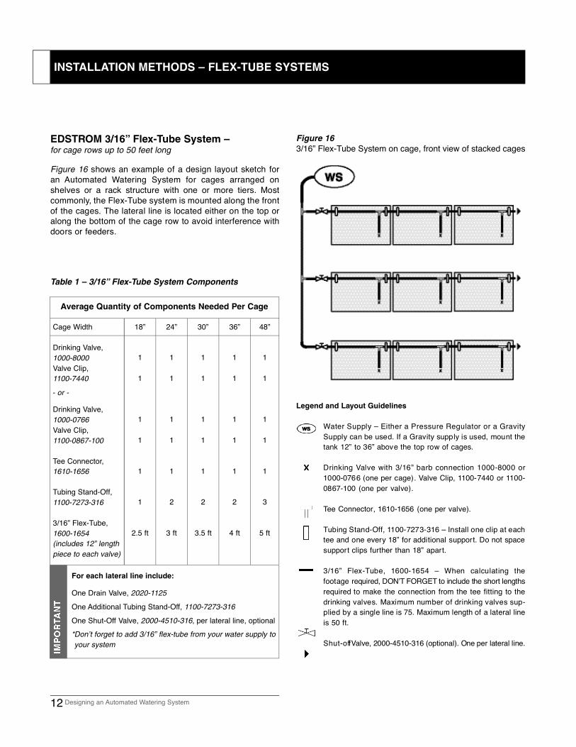
Figure 16 shows an example of a design layout sketch foran Automated Watering System for cages arranged onshelves or a rack structure with one or more tiers. Mostc o m m o n l y, the Flex-Tube system is mounted along the frontof the cages. The lateral line is located either on the top oralong the bottom of the cage row to avoid interference withdoors or feeders.
Figure 16
3/16” Flex-Tube System on cage, front view of stacked cages
12 Designing an Automated Watering System
Legend and Layout Guidelines
Water Supply – Either a Pressure Regulator or a GravitySupply can be used. If a Gravity supply is used, mount thetank 12” to 36” above the top row of cages.
Drinking Valve with 3/16” barb connection 1000-8000 or1000-0766 (one per cage). Valve Clip, 1100-7440 or 11 0 0 -0867-100 (one per valve).
Tee Connector, 1610-1656 (one per valve).
Tubing Stand-Off, 1100-7273-316 – Install one clip at eachtee and one every 18” for additional support. Do not spacesupport clips further than 18” apart.
3/16” Flex-Tube, 1600-1654 – When calculating thefootage required, DON’T F O R G E T to include the short lengthsrequired to make the connection from the tee fitting to thedrinking valves. Maximum number of drinking valves sup-plied by a single line is 75. Maximum length of a lateral lineis 50 ft.
S h u t - o ff Valve, 2000-4510-316 (optional). One per lateral line.
For each lateral line include:
One Drain Valve, 2020-1125
One Additional Tubing Stand-Off, 1100-7273-316
One Shut-Off Valve, 2000-4510-316, per lateral line, optional*Don’t forget to add 3/16” flex-tube from your water supply to your system
EDSTROM 3/16” Flex-Tube System –for cage rows up to 50 feet long
Table 1 – 3/16” Flex-Tube System Components
Average Quantity of Components Needed Per Cage
Cage Width
Drinking Valve,1000-8000Valve Clip,1100-7440
Drinking Valve,1000-0766Valve Clip,1100-0867-100
Tee Connector,1610-1656
Tubing Stand-Off,1100-7273-316
3/16” Flex-Tube,1600-1654 (includes 12” length piece to each valve)
1 2 3
2.5 ft 3.5 ft3 ft 4 ft 5 ft
18” 24” 30” 36” 48”
2 2
1 1 1 1 1
1 1 1 1 1
1 1 1 1 1
1 1 1 1 1
1 1 1 1 1
- or -
INSTALLATION METHODS – FLEX-TUBE SYSTEMS
Legend and Layout Guidelines
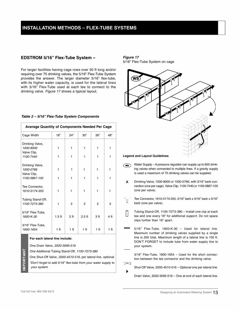
Water Supply – A pressure regulator can supply up to 600 drink-ing valves when connected to multiple lines. If a gravity supplyis used a maximum of 75 drinking valves can be supplied.
Drinking Valve, 1000-8000 or 1000-0766, with 3/16” barb con-nection (one per cage). Valve Clip, 1100-7440 or 11 0 0 - 0 8 6 7 -100(one per valve).
Tee Connector, 1610-5174-355, 5/16” barb x 5/16” barb x 3/16”barb (one per valve).
Tubing Stand-Off, 1100-7273-380 – Install one clip at eachtee and one every 18” for additional support. Do not spaceclips further than 18” apart.
5/16” Flex-Tube, 1600-K-30 – Used for lateral line.Maximum number of drinking valves supplied by a singleline is 200 total. Maximum length of a lateral line is 100 ft.D O N ’ T F O R G E T to include tube from water supply line toyour system.
3/16” Flex-Tube, 1600-1654 – Used for the short connec-tion between the tee connector and the drinking valve.
S h u t - O ff Valve, 2000-4510-516 – Optional one per lateral line.
Drain Valve, 2020-3095-516 – One at end of each lateral line.
Figure 17
5/16” Flex-Tube System on cage
For larger facilities having cage rows over 50 ft long and/orrequiring over 75 drinking valves, the 5/16” Flex-Tube Systemprovides the answer. The larger diameter 5/16” flex-tube,with its higher water capacity, is used for the lateral lineswith 3/16” Flex-Tube used at each tee to connect to thedrinking valve. Figure 17 shows a typical layout.
Designing an Automated Watering System 13
For each lateral line include:
One Drain Valve, 2020-3095-516
One Additional Tubing Stand-Off, 1100-7273-380
One Shut-Off Valve, 2000-4510-516, per lateral line, optional
*Don’t forget to add 5/16” flex-tube from your water supply to your system
Table 2 – 5/16” Flex-Tube System Components
Average Quantity of Components Needed Per Cage
Cage Width
Drinking Valve,1000-8000Valve Clip,1100-7440
Drinking Valve,1000-0766Valve Clip,1100-0867-100
Tee Connector,1610-5174-355
Tubing Stand-Off,1100-7273-380
5/16” Flex-Tube,1600-K-30
3/16” Flex-Tube,1600-1654
1 2 3
1.5 ft 2.5 ft2 ft 3 ft 4 ft
18” 24” 30” 36” 48”
2 2
1 1 1 1 1
1 1 1 1 1
1 1 1 1 1
1 1 1 1 1
1 1 1 1 1
1 ft 1 ft1 ft 1 ft 1 ft
EDSTROM 5/16” Flex-Tube System –
INSTALLATION METHODS – FLEX-TUBE SYSTEMS
Call toll free: 800 558 5913
Legend and Layout Guidelines
Water Supply – A Pressure Regulator can supply up to 600Drinking Valves. If a Gravity Supply is used a maximum of75 Valves can be supplied. (A Flex-Hose Hookup Kit, 7450-5400, is available to make the connection between the watersupply and the rigid PVC piping.)
Drinking Valve, 1000-8010 or 1000-0768, with 1/8” mpt con-nection (one per cage). Tee Adaptor Fitting, 1630-2914-100,1/2” soc x 1/2” soc x 1/8” fpt (one per valve).
1/2” PVC Pipe, 1600-2077-060 (5-ft section). Maximumnumber of drinking valves supplied by a single line is 600.The maximum length of a lateral line is 200 ft.
Wire Pipe Tie, 0120-F-50 (one per valve). The pipe shouldbe supported every 36” or less; install additional supportsas required.
Drain Valve, 2000-4043 and 1630-9028-001 – One at theend of each lateral line.
Shut-Off Valve, 2000-H-900 1/2” soc x 1/2” soc – Optionalone per lateral line.
Refer to the Parts List on page 23 to select the components for yourrigid PVC piping.
Rigid PVC pipe can be used for large facilities requiring linesover 100 ft or having over 200 drinking valves. Rigid PVCpipe is the preferred piping system for animals and birds thathave the agility and strength to pull the Flex-Tube Systemo ff the cage. Figure 18 shows a typical layout with rigid PVCp i p e .
Figure 18
Rigid PVC Pipe System on Cages
14 Designing an Automated Watering System
Do not use a saw to cut the PVC pipe to length.This produces many fine particles of plastic whichfall inside the pipe, are very difficult to flush outand later can become lodged in the DrinkingValve, causing leaks.
Use EDSTROM’s Pipe Cutter Tool, 0129-HV-100.
Typical Rigid PVC Pipe Layout –for cage rows up to 200 feet long
INSTALLATION METHODS – RIGID PVC PIPE SYSTEM
For each lateral line include:
One Drain Valve, 2000-4043 and 1630-9028-001, one at theend of each lateral line
One Shut-Off Valve, 2000-H-900, per lateral line, optional
*Don’t forget to add 1/2” PVC pipe from your water supply to your system
Table 3 – Rigid PVC Pipe Layout Components
Average Quantity of Components Needed Per Cage
Cage Width
Drinking Valve,1000-8010
Drinking Valve,1000-0768
Tee Adaptor Fitting,1630-2914-100
Wire Pipe Tie,0120-F-50
1/2” PVC Pipe,1600-2077-060 (5 ft. section)
1.5 ft 2.5 ft2 ft 3 ft 4 ft
18” 24” 30” 36” 48”
1 1 1 1 1
1 1 1 1 1
1 1 1 1 1
1 1 1 1 2
- or -
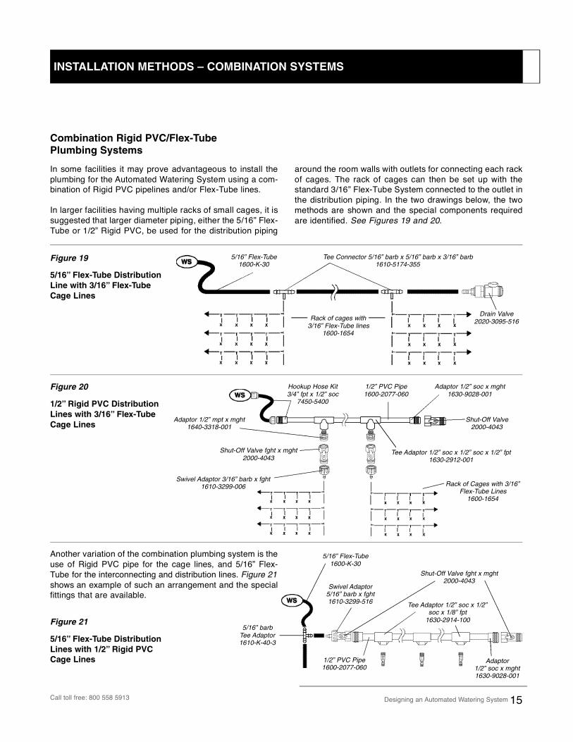
In some facilities it may prove advantageous to install theplumbing for the Automated Watering System using a com-bination of Rigid PVC pipelines and/or Flex-Tube lines.
In larger facilities having multiple racks of small cages, it issuggested that larger diameter piping, either the 5/16” Flex-Tube or 1/2” Rigid PVC, be used for the distribution piping
around the room walls with outlets for connecting each rackof cages. The rack of cages can then be set up with thestandard 3/16” Flex-Tube System connected to the outlet inthe distribution piping. In the two drawings below, the twomethods are shown and the special components requiredare identified. See Figures 19 and 20.
5/16” Flex-Tube1600-K-30
Tee Connector 5/16” barb x 5/16” barb x 3/16” barb1610-5174-355
Drain Valve2020-3095-516Rack of cages with
3/16” Flex-Tube lines1600-1654
Swivel Adaptor 3/16” barb x fght1610-3299-006
Adaptor 1/2” soc x mght1630-9028-001
Hookup Hose Kit3/4” fpt x 1/2” soc
7450-5400
Tee Adaptor 1/2” soc x 1/2” soc x 1/2” fpt1630-2912-001
Adaptor 1/2” mpt x mght1640-3318-001
1/2” PVC Pipe1600-2077-060
Rack of Cages with 3/16”Flex-Tube Lines
1600-1654
Shut-Off Valve fght x mght2000-4043
Shut-Off Valve2000-4043
5/16” Flex-Tube1600-K-30
Swivel Adaptor 5/16” barb x fght1610-3299-516
Shut-Off Valve fght x mght2000-4043
Adaptor 1/2” soc x mght1630-9028-001
Tee Adaptor 1/2” soc x 1/2”soc x 1/8” fpt
1630-2914-100
1/2” PVC Pipe1600-2077-060
Designing an Automated Watering System 15
Combination Rigid PVC/Flex-Tube
Plumbing Systems
Another variation of the combination plumbing system is theuse of Rigid PVC pipe for the cage lines, and 5/16” Flex-Tube for the interconnecting and distribution lines. Figure 21shows an example of such an arrangement and the specialfittings that are available.
Figure 19
5/16” Flex-Tube Distribution
Line with 3/16” Flex-Tube
Cage Lines
Figure 20
1/2” Rigid PVC Distribution
Lines with 3/16” Flex-Tube
Cage Lines
Figure 21
5/16” Flex-Tube Distribution
Lines with 1/2” Rigid PVC
Cage Lines
INSTALLATION METHODS – COMBINATION SYSTEMS
Call toll free: 800 558 5913
5/16” barb Tee Adaptor 1610-K-40-3
Flushing the Lines – On initial hookup of the water supply to a newly installed piping system, all the lines should be thor-oughly flushed to remove any particles of dirt or debris thatmay have fallen inside the pipe lines during assembly. If thelines are not flushed, then these particles will be carried intothe drinking valve, where they may become lodged on theseal and cause a leak.
To flush the line, open the drain valve at the end of the line,and allow water to flow out for several minutes. Repeat thisprocedure for each drain valve in your system. Start on thelines that are closest to the water supply and work your wayto those farthest away.
Actuate each Drinking Valve – To confirm the proper actuation of the drinking valves, each one should be manu-ally actuated and the flow of water observed. In Flex-Tu b einstallations, air trapped in the short length of the Flex-Tubeconnection between the Valve and the lateral line must bepushed out before water begins to flow evenly.
Sanitizing the Plumbing System – For household potable water systems it is good plumbing practice to sanitize thelines on start-up to eliminate bacteria in the pipe lines. T h i sis also a good practice to follow for your automated wateringsystem. Sanitization of the lines can be easily done by fillingthem with a chlorine solution and allowing to stand for at least30 minutes. It is recommended that the chlorine solution havea concentration of 5 to 10 parts per million (ppm). This will notharm the animals/birds if they should drink it. (Normal munic-ipal water supplies have chlorine levels of 0.5 to 2 ppm.)
You can easily prepare a chlorine solution by mixing house-hold chlorine bleach and water. A solution of 1/2 teaspoon per7 gallons water will produce a solution of approximately 5ppm. Use EDSTROM’s Chlorine Test Kit, 2400-6683, whichhas a range of 0 to 20 ppm, or 2400-6684 (0 to 3.5 ppm) totest your mix.
The method of filling your pipelines with the sanitizing solutionwill depend on the water supply method you are using. If astorage tank is used, you can fill it directly with the sanitizingsolution. If a float tank is used, the fresh water supply must beshut off, and then the tank must be filled with the solution. Ifthe basic pressure station is used, it can be temporarily dis-connected and a storage tank, filled with the solution, con-nected in its place. With the deluxe pressure regulator station,a temporary storage tank can be connected directly to theinjection port and the fresh water supply turned off. S e eFigures 22 and 23 on page 17.
Once you have the sanitizing solution as your water supply,you should flush each line just long enough to fill it with thesolution. Then allow the system to sit for at least 30 minutesbefore flushing the lines with fresh water.
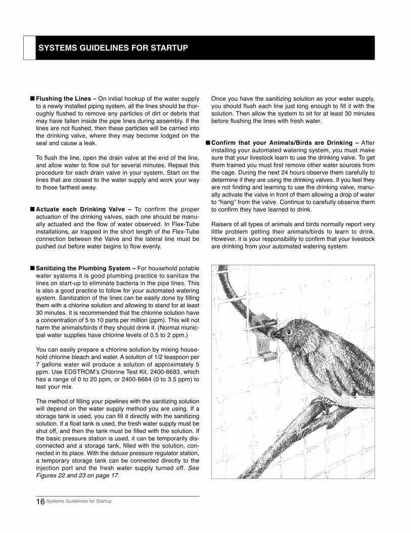
Confirm that your Animals/Birds are Drinking – After installing your automated watering system, you must makesure that your livestock learn to use the drinking valve. To getthem trained you must first remove other water sources fromthe cage. During the next 24 hours observe them carefully todetermine if they are using the drinking valves. If you feel theyare not finding and learning to use the drinking valve, manu-ally activate the valve in front of them allowing a drop of waterto “hang” from the valve. Continue to carefully observe themto confirm they have learned to drink.
Raisers of all types of animals and birds normally report verylittle problem getting their animals/birds to learn to drink.However, it is your responsibility to confirm that your livestockare drinking from your automated watering system.
16 Systems Guidelines for Startup
SYSTEMS GUIDELINES FOR STARTUP
Routine Operation Check – It is recommended that you routinely check the operation of all drinking valves in your oper-ation as part of your normal animal husbandry procedures.
Regular Flushing and Sanitization of the System – Becausesmaller animals and birds drink such a small amount of water,the total flow of water through the system is very low. Toensure the freshness of the water in your lines, all linesshould be flushed at least once a week. Refer to the proce-dure for flushing the lines in the Startup Section on page 16.
In addition, to eliminate the chance for bacterial or algaegrowth in the system it should be sanitized at least twice amonth. This is especially important if your fresh water supplyis not chlorinated.
Use of Medications and Vitamins in the Water Supply –
Most water soluble medications and vitamins recommendedfor use in the animal drinking water can be dispensed throughthe automated watering system. Whenever an additive is putin the water supply, care must be taken to confirm that itc o mpletely dissolves and stays in suspension in the water toavoid potential problems with residues fouling the operationof the drinking valves.
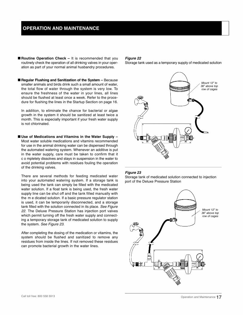
There are several methods for feeding medicated waterinto your automated watering system. If a storage tank isbeing used the tank can simply be filled with the medicatedwater solution. If a float tank is being used, the fresh watersupply line can be shut off and the tank filled manually withthe m e dicated solution. If a basic pressure regulator stationis used, it can be temporarily disconnected, and a storagetank filled with the solution connected in its place. See Figure22. The Deluxe Pressure Station has injection port valveswhich permit turning off the fresh water supply and connect-ing a temporary storage tank of medicated solution to supplythe system. See Figure 23.
After completing the dosing of the medication or vitamins, thesystem should be flushed and sanitized to remove anyresidues from inside the lines. If not removed these residuescan promote bacterial growth in the water lines.
Figure 22
Storage tank used as a temporary supply of medicated solution
Figure 23
Storage tank of medicated solution connected to injectionport of the Deluxe Pressure Station
Operation and Maintenance 17
Mount 12” to36” above toprow of cages
Mount 12” to36” above toprow of cages
OPERATION AND MAINTENANCE
Call toll free: 800 558 5913
When animals are in transit or at shows, the EDSTROMWater Buddy™ Animal Water Bottle provides your animalswith clean water through the same drip-free drinking valvethey are accustomed to using. The EDSTROM Drinking Valveis ideal for transit cages, since it will not leak water due tomovement and/or bouncing of the cage.
In addition, the Water Buddy can be used to provide medicate dwater to an individual cage of animals in your facility. Simplyremove the regular drinking valve from the cage and attachthe Water Buddy filled with the medicated water solution.
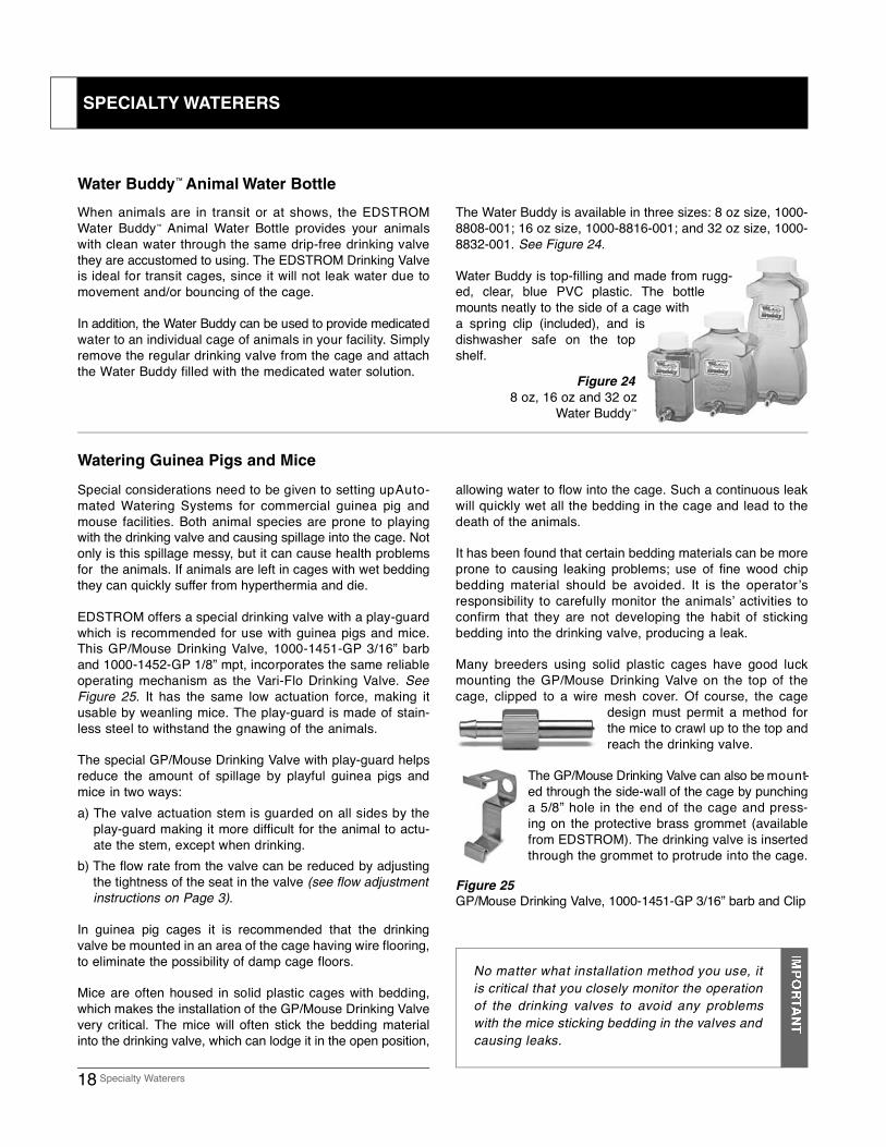
The Water Buddy is available in three sizes: 8 oz size, 1000-8808-001; 16 oz size, 1000-8816-001; and 32 oz size, 1000-8832-001. See Figure 24.
Water Buddy is top-filling and made from rugg-ed, clear, blue PVC plastic. The bottlemounts neatly to the side of a cage witha spring clip (included), and isd i s h w a s her safe on the topshelf.
Special considerations need to be given to setting up A u t o -mated Watering Systems for commercial guinea pig andmouse facilities. Both animal species are prone to playingwith the drinking valve and causing spillage into the cage. Notonly is this spillage messy, but it can cause health problemsfor the animals. If animals are left in cages with wet beddingthey can quickly suffer from hyperthermia and die.
EDSTROM offers a special drinking valve with a play-guardwhich is recommended for use with guinea pigs and mice.This GP/Mouse Drinking Valve, 1000-1451-GP 3/16” barband 1000-1452-GP 1/8” mpt, incorporates the same reliableoperating mechanism as the Vari-Flo Drinking Valve. S e eFigure 25. It has the same low actuation force, making itusable by weanling mice. The play-guard is made of stain-less steel to withstand the gnawing of the animals.
The special GP/Mouse Drinking Valve with play-guard helpsreduce the amount of spillage by playful guinea pigs andmice in two ways:a) The valve actuation stem is guarded on all sides by the
play-guard making it more difficult for the animal to actu-ate the stem, except when drinking.
b) The flow rate from the valve can be reduced by adjusting the tightness of the seat in the valve (see flow adjustmentinstructions on Page 3).
In guinea pig cages it is recommended that the drinkingvalve be mounted in an area of the cage having wire flooring,to eliminate the possibility of damp cage floors.
Mice are often housed in solid plastic cages with bedding,which makes the installation of the GP/Mouse Drinking Va l v every critical. The mice will often stick the bedding materialinto the drinking valve, which can lodge it in the open position,
allowing water to flow into the cage. Such a continuous leakwill quickly wet all the bedding in the cage and lead to thedeath of the animals.
It has been found that certain bedding materials can be moreprone to causing leaking problems; use of fine wood chipbedding material should be avoided. It is the operator ’sresponsibility to carefully monitor the animals’ activities toconfirm that they are not developing the habit of stickingbedding into the drinking valve, producing a leak.
Many breeders using solid plastic cages have good luckmounting the GP/Mouse Drinking Valve on the top of thecage, clipped to a wire mesh cover. Of course, the cage
design must permit a method forthe mice to crawl up to the top andreach the drinking valve.
The GP/Mouse Drinking Valve can also be m o u n t-ed through the side-wall of the cage by punchinga 5/8” hole in the end of the cage and press-ing on the protective brass grommet (availablefrom EDSTROM). The drinking valve is insertedthrough the grommet to protrude into the cage.
Figure 25
GP/Mouse Drinking Valve, 1000-1451-GP 3/16” barb and Clip
18 Specialty Waterers
No matter what installation method you use, itis critical that you closely monitor the operationof the drinking valves to avoid any problemswith the mice sticking bedding in the valves andcausing leaks.
Water Buddy™ Animal Water Bottle
Watering Guinea Pigs and Mice
SPECIALTY WATERERS
Figure 24
8 oz, 16 oz and 32 ozWater Buddy™
EDSTROM Drinking Valves have been used extensively bycommercial aviaries and exotic bird breeding facilities aroundthe world for years with great success. Using the drinkingvalve assures a continuous supply of clean, fresh water to thebirds. Providing a clean water supply in sanitary dispensers iscritical to maintaining the good health of the birds, and theEDSTROM Drinking Valve does this for you.
In addition to eliminating the labor and time required to cleanand change water bottles, producers also report that becausethey don’t have to enter the breeding rooms as often, thebirds’ natural activities are less often interrupted.
Both the Vari-Flo Valve and the Original Drinking Valve can beoperated by most straight-billed and hooked-billed breeds ofbirds. The Vari-Flo Valve, with its low actuation force, is thepreferred drinking valve for finches and other small birds.
The drinking valve should be located on the cage side at aheight easily accessible by the bird, either standing on aperch or on the cage floor. By mounting the drinking valvehorizontally, the last drop of water remains in the barrel of thevalve. This small amount of water attracts the birds to thevalve, encouraging them to play with the valve, so they quick-ly learn how to operate it.
When installed in large flights, it is recommended that one drink-ing valve be provided for every six to eight birds. T h evalves should be spaced far enough apart to prevent thedominant bird from controlling access to all the drinking
Vari-Flo Valve1000-8000
Original Valve1000-0766
Figure 27
Pivoting Stem Cup, 1000-1900 and Clip, 1100-0867-100
Figure 28
Trigger Cup, 0100-H-8L
Exotic Bird Watering | Cup Waterers for Poultry 19
EDSTROM also offers a line of Cup Waterers for use with alltypes of poultry including pigeons, quails, pheasants, doves,and chickens. Models are available which easily adapt toinstallation in the hobbyist’s facility as well as commercialproduction facilities.
The Pivoting Stem Cup Wa t e r e r, see Figure 27, is availablewith either 1/8” mpt connection, 1000-5552, or with 3/16” barbconnection, 1000-1900, for use in a Flex-Tube System. T h evalve mechanism used in the Pivoting Stem Cup Waterer isidentical to the design of the Original Drinking Valve. T h ebowl of the cup is made of plastic and can be easily removedfor cleaning.
A Trigger Cup Waterer used in commercial chicken hous-es around the world is also offered by EDSTROM. T h eHart Trigger Cup, 0100-H-8L, has a 1/8” mpt connection,and is made of rugged plastic. See Figure 28.
Cup Waterers for Poultry
For large birds like parrots, macaws, and cockatoos,EDSTROM has a large, rugged stainless steel ParrotValve, 1000-4005. The Parrot Valve has a 1/2” mptconnection which can be easily installed in a RigidPVC pipe system using the Tee Adaptor Fitting, 1630-2 9 1 2 - 0 0 1 .
The Parrot Valve
Parrot Valve1000-4005
Tee Adaptor Fitting1630-2912-001
EXOTIC BIRD WATERING
Call toll free: 800 558 5913
20 Trouble Shooting Guide
Drinking Valve Leaking
The primary cause of a leak from the valve is the collec-
tion of part i cles on the O-ring seal inside the va l v e. A sexplained on page 4, the water shut-off seal occurs betweenthe head of the stem and the O-ring seal. When particlesbecome lodged on the O-ring, it will prevent the stem headfrom sealing completely and a leak will occur.
If you experience this problem with your valves, you shoulddisassemble the valve and inspect the O-ring to see whatcontamination can be found. It is helpful to have a good lightsource and a magnifying glass when inspecting the surfaceof the O-ring. If residue is found on the O-ring it is best toreplace it with a new one. It is almost impossible to “clean”an O-ring that has particles embedded in it.
A common source of leak producing part i cles is fine
sand in the water supply. If your water supply has sandin it, an 80 micron or finer water filter (see page 10, flush-able filter, 2100-6120-200) must be used on the water supplyto the system.
Should leaks occur immediately in a new ly installed
Rigid PVC pipe system, the likely cause is shav i n g s
f rom the cutting of the PVC pipe which were not flushed
out of the distribution lines during installation. W h e nthe system is started up, the particles flow into the drinkingvalve and become lodged on the O-ring, causing a leak. Tostop the leak each valve will need to be opened and the par-ticles removed or the O-ring replaced.
Another possible cause of a leak would be corro s i o n
of the brass seat under the O-ring. Brass is an extremelyrugged, sanitary and corrosion resistant material and is idealfor drinking water that is in the normal and safe range of 6.5to 8.5 pH. However, when exposed to high acid levels thesurfaces of both brass and stainless steel can be damagedby corrosion. For the well being of both your animals and yourdrinking valves use caution when using water additives andtreatments to avoid exceeding this pH range.
A valve can also leak if animals stick bedding or fe e d
inside the drinking va l v e, and thereby fo rce the stem to
the actuated position. This can be avoided by locating thevalve further away from the feed source in the cage or high-er in the cage making it more difficult for the animals to playwith the valve.
No Flow from the Drinking Valve
If you are unable to get water to flow from the valve when theStem is actuated, check the following:
F i rst confirm that you have water ava i l a ble in the distri-
bution line to the valve. Check that the pressure is properlyregulated, 0.5 to 5 psi. If the valve is connected to highwater pressures the stem head will become embedded intothe O-ring and not allow water to be released.
Check that the valve seat has not been turned too tightly
into the valve cap. As described on Page 3, the rate thatwater is released from the Vari-Flo Valve can be adjusted byloosening or tightening the seat into the cap. Over-tighteningof the seat in both the Vari-Flo and Original Valves can com-pletely shut off the flow of water through the valve.
C h e ck that the valve has not become plugged internally
with algae or slime bu i l d u p . Disassemble the valve andclean all internal parts. Be sure that the holes through thediaphragm are open. The valve components can be cleanedin vinegar or a bathroom cleanser to remove lime deposits.
Winterization of a Watering System
The EDSTROM Automated Watering System has beendesigned for use in facilities not exposed to freezingt e mperatures. Although the Flex-Tube System is very sel-dom damaged by effects of freezing temperatures, thereis no easy method to protect it from freezing. The use ofe l e ctrical heat tapes with the Flex-Tube System is NOTr e commended. Some of the methods used by producersto deal with overnight mild freezing temperaturesi n c l u d e :1 . Turning off the water supply in the evening and allow-
i n gthe animals to drink the system dry overnight.
2 . Opening the drain-valve at the end of each lateral line allowing a slow trickle of water to run continuously.
The Rigid PVC Pipe System is more susceptible tod a mage by water freezing inside the lines. T h e r e f o r ePVC distribution lines should be drained to avoid thepossibility of the pipe or fittings being split by freezingw a t e r.
It is possible to install heat tape on a Rigid Pipe System,using care to install according to manufacturer’s instruc-tions. The heat tape should be located on the pipe in aposition that cannot be accessed by the animals. To pro-tect yourself and your animals from possible electrical
TROUBLE SHOOTING GUIDE
Parts List 21
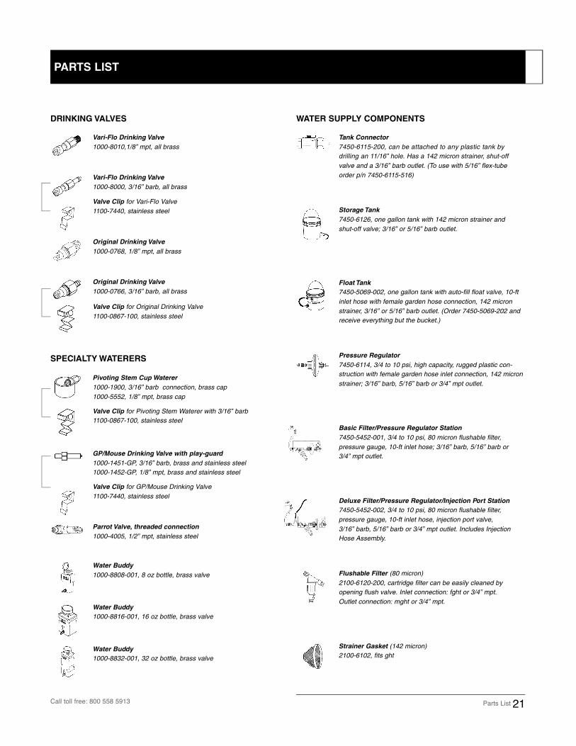
DRINKING VALVES
SPECIALTY WATERERS
WATER SUPPLY COMPONENTS
Vari-Flo Drinking Valve
1000-8010,1/8” mpt, all brass
Vari-Flo Drinking Valve
1000-8000, 3/16” barb, all brass
Valve Clip for Vari-Flo Valve1100-7440, stainless steel
Original Drinking Valve
1000-0768, 1/8” mpt, all brass
Original Drinking Valve
1000-0766, 3/16” barb, all brass
Valve Clip for Original Drinking Valve1100-0867-100, stainless steel
Pivoting Stem Cup Waterer
1000-1900, 3/16” barb connection, brass cap1000-5552, 1/8” mpt, brass cap
Valve Clip for Pivoting Stem Waterer with 3/16” barb1100-0867-100, stainless steel
GP/Mouse Drinking Valve with play-guard
1000-1451-GP, 3/16” barb, brass and stainless steel1000-1452-GP, 1/8” mpt, brass and stainless steel
Valve Clip for GP/Mouse Drinking Valve1100-7440, stainless steel
Parrot Valve, threaded connection
1000-4005, 1/2” mpt, stainless steel
Water Buddy
1000-8808-001, 8 oz bottle, brass valve
Water Buddy
1000-8816-001, 16 oz bottle, brass valve
Water Buddy
1000-8832-001, 32 oz bottle, brass valve
Tank Connector
7 4 5 0 - 6 115-200, can be attached to any plastic tank bydrilling an 11/16” hole. Has a 142 micron strainer, shut-offvalve and a 3/16” barb outlet. (To use with 5/16” flex-tube order p/n 7450-6115-516)
Storage Tank
7450-6126, one gallon tank with 142 micron strainer and shut-off valve; 3/16” or 5/16” barb outlet.
Float Tank
7450-5069-002, one gallon tank with auto-fill float valve, 10-ftinlet hose with female garden hose connection, 142 micronstrainer, 3/16” or 5/16” barb outlet. (Order 7450-5069-202 andreceive everything but the bucket.)
Pressure Regulator
7450-6114, 3/4 to 10 psi, high capacity, rugged plastic con-struction with female garden hose inlet connection, 142 micronstrainer; 3/16” barb, 5/16” barb or 3/4” mpt outlet.
Basic Filter/Pressure Regulator Station
7450-5452-001, 3/4 to 10 psi, 80 micron flushable filter,pressure gauge, 10-ft inlet hose; 3/16” barb, 5/16” barb or 3/4” mpt outlet.
Deluxe Filter/Pressure Regulator/Injection Port Station
7450-5452-002, 3/4 to 10 psi, 80 micron flushable filter,pressure gauge, 10-ft inlet hose, injection port valve, 3/16” barb, 5/16” barb or 3/4” mpt outlet. Includes InjectionHose Assembly.
Flushable Filter (80 micron)2100-6120-200, cartridge filter can be easily cleaned by opening flush valve. Inlet connection: fght or 3/4” mpt. Outlet connection: mght or 3/4” mpt.
Strainer Gasket (142 micron)2100-6102, fits ght
PARTS LIST
Call toll free: 800 558 5913
22 Parts List
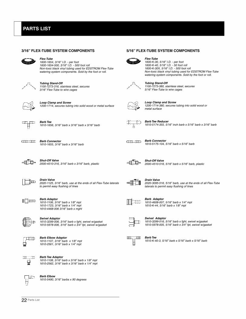
3/16” FLEX-TUBE SYSTEM COMPONENTS 5/16” FLEX-TUBE SYSTEM COMPONENTS
Flex-Tube
1600-1654, 3/16” I.D. - per foot1600-1654-500, 3/16” I.D. - 500 foot rollNon-toxic black vinyl tubing used for EDSTROM Flex-Tube watering system components. Sold by the foot or roll.
Tubing Stand-Off1100-7273-316, stainless steel, secures3/16” Flex-Tube to wire cages
Loop Clamp and Screw1200-1714, secures tubing into solid wood or metal surface
Barb Tee1610-1656, 3/16” barb x 3/16” barb x 3/16” barb
Barb Connector1610-1655, 3/16” barb x 3/16” barb
Shut-Off Valve
2000-4510-316, 3/16” barb x 3/16” barb, plastic
Drain Valve
2020-1125, 3/16” barb, use at the ends of all Flex-Tube lateralsto permit easy flushing of lines
Barb Adaptor1610-1106, 3/16” barb x 1/8” mpt1610-1723, 3/16” barb x 1/4” mpt1610-4468-006 3/16” barb x mght
Swivel Adaptor1610-3299-006, 3/16” barb x fght, swivel w/gasket1610-5978-006, 3/16” barb x 3/4” fpt, swivel w/gasket
Barb Elbow Adaptor
1610-1107, 3/16” barb x 1/8” mpt1610-2561, 3/16” barb x 1/4” mpt
Barb Tee Adaptor1610-1108, 3/16” barb x 3/16” barb x 1/8” mpt1610-2562, 3/16” barb x 3/16” barb x 1/4” mpt
Barb Elbow1610-5490, 3/16” barbs x 90 degrees
Flex-Tube 1600-K-30, 5/16” I.D. - per foot1600-K-40, 5/16” I.D. - 50 foot roll1600-K-30X, 5/16” I.D. - 500 foot rollNon-toxic black vinyl tubing used for EDSTROM Flex-Tube watering system components. Sold by the foot or roll.
Tubing Stand-Off1100-7273-380, stainless steel, secures5/16” Flex-Tube to wire cages
Loop Clamp and Screw1200-1714-380, secures tubing into solid wood or metal surface
Barb Tee Reducer1610-5174-355, 5/16” inch barb x 5/16” barb x 3/16” barb
Barb Connector1610-5175-104, 5/16” barb x 5/16” barb
Shut-Off Valve
2000-4510-516, 5/16” barb x 5/16” barb, plastic
Drain Valve2020-3095-516, 5/16” barb, use at the ends of all Flex-Tube laterals to permit easy flushing of lines
Barb Adaptor
1610-4608-007, 5/16” barb x 1/4” mpt1610-K-44, 5/16” barb x 1/8” mpt
Swivel Adaptor1610-3299-516, 5/16” barb x fght, swivel w/gasket1610-5978-005, 5/16” barb x 3/4” fpt, swivel w/gasket
Barb Tee1610-K-40-3, 5/16” barb x 5/16” barb x 5/16” barb
PARTS LIST
Parts List 23
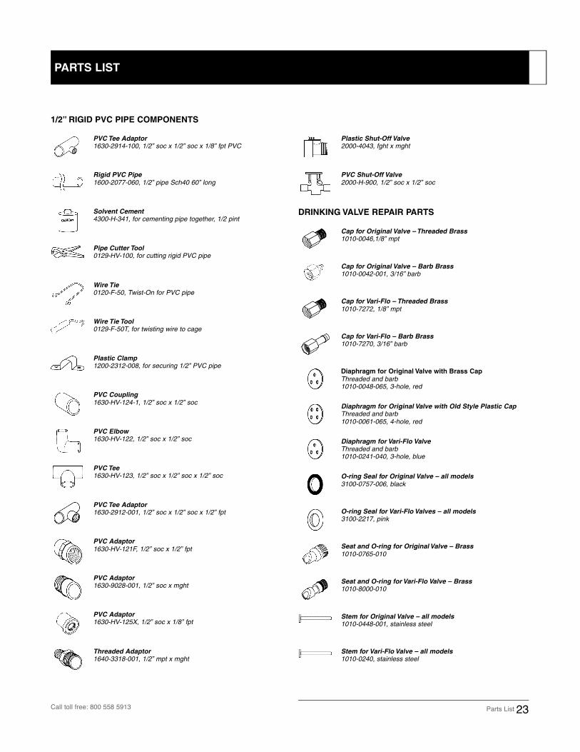
1/2” RIGID PVC PIPE COMPONENTS
DRINKING VALVE REPAIR PARTS
PVC Tee Adaptor1630-2914-100, 1/2” soc x 1/2” soc x 1/8” fpt PVC
Rigid PVC Pipe
1600-2077-060, 1/2” pipe Sch40 60” long
Solvent Cement4300-H-341, for cementing pipe together, 1/2 pint
Pipe Cutter Tool0129-HV-100, for cutting rigid PVC pipe
Wire Tie0120-F-50, Twist-On for PVC pipe
Wire Tie Tool0129-F-50T, for twisting wire to cage
Plastic Clamp1200-2312-008, for securing 1/2” PVC pipe
PVC Coupling
1630-HV-124-1, 1/2” soc x 1/2” soc
PVC Elbow1630-HV-122, 1/2” soc x 1/2” soc
PVC Tee1630-HV-123, 1/2” soc x 1/2” soc x 1/2” soc
PVC Tee Adaptor1630-2912-001, 1/2” soc x 1/2” soc x 1/2” fpt
PVC Adaptor
1630-HV-121F, 1/2” soc x 1/2” fpt
PVC Adaptor1630-9028-001, 1/2” soc x mght
Threaded Adaptor1640-3318-001, 1/2” mpt x mght
Plastic Shut-Off Valve2000-4043, fght x mght
PVC Shut-Off Valve
2000-H-900, 1/2” soc x 1/2” soc
Cap for Original Valve – Threaded Brass1010-0046,1/8” mpt
Cap for Original Valve – Barb Brass1010-0042-001, 3/16” barb
Cap for Vari-Flo – Threaded Brass
1010-7272, 1/8” mpt
Cap for Vari-Flo – Barb Brass1010-7270, 3/16” barb
Diaphragm for Original Valve with Brass Cap
Threaded and barb1010-0048-065, 3-hole, red
Diaphragm for Original Valve with Old Style Plastic CapThreaded and barb1010-0061-065, 4-hole, red
Diaphragm for Vari-Flo ValveThreaded and barb1010-0241-040, 3-hole, blue
O-ring Seal for Original Valve – all models
3100-0757-006, black
O-ring Seal for Vari-Flo Valves – all models3100-2217, pink
Seat and O-ring for Original Valve – Brass
1010-0765-010
Seat and O-ring for Vari-Flo Valve – Brass1010-8000-010
Stem for Original Valve – all models1010-0448-001, stainless steel
Stem for Vari-Flo Valve – all models1010-0240, stainless steel
PVC Adaptor1630-HV-125X, 1/2” soc x 1/8” fpt
PARTS LIST
Call toll free: 800 558 5913
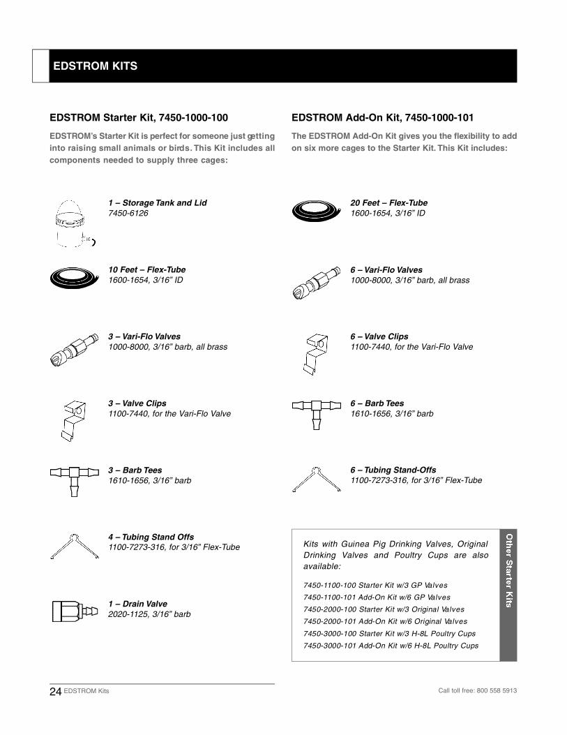
E D S T RO M ’s Starter Kit is perfect for someone just ge t t i n g
into raising small animals or bird s . This Kit includes all
components needed to supply three cage s :
24 EDSTROM Kits Call toll free: 800 558 5913
The EDSTROM Add-On Kit gives you the flexibility to add
on six more cages to the Starter Kit. This Kit includes:
EDSTROM Starter Kit, 7450-1000-100 EDSTROM Add-On Kit, 7450-1000-101
1 – Storage Tank and Lid
7450-6126
10 Feet – Flex-Tube
1600-1654, 3/16” ID
3 – Vari-Flo Valves
1000-8000, 3/16” barb, all brass
3 – Valve Clips
1100-7440, for the Vari-Flo Valve
3 – Barb Tees
1610-1656, 3/16” barb
4 – Tubing Stand Offs
1100-7273-316, for 3/16” Flex-Tube
1 – Drain Valve
2020-1125, 3/16” barb
20 Feet – Flex-Tube
1600-1654, 3/16” ID
6 – Vari-Flo Valves
1000-8000, 3/16” barb, all brass
6 – Valve Clips
1100-7440, for the Vari-Flo Valve
6 – Barb Tees
1610-1656, 3/16” barb
6 – Tubing Stand-Offs
1100-7273-316, for 3/16” Flex-Tube
Kits with Guinea Pig Drinking Valves, OriginalDrinking Valves and Poultry Cups are alsoa v a i l a b l e :
7 4 5 0 - 1100-100 Starter Kit w/3 GP Va l v e s
7 4 5 0 - 1100-101 Add-On Kit w/6 GP Va l v e s
7450-2000-100 Starter Kit w/3 Original Va l v e s
7450-2000-101 Add-On Kit w/6 Original Va l v e s
7450-3000-100 Starter Kit w/3 H-8L Poultry Cups
7450-3000-101 Add-On Kit w/6 H-8L Poultry Cups
EDSTROM KITS


4220-SB6063 01/05
819 Bakke Ave • Waterford WI 53185 • Tel: 262 534 5181 • 800 558 5913 • Fax: 262 534 5184
CONTACT US TO FIND A DEALER NEAR YOU: