Embed Size (px)
Citation preview
UNCLASSIFIED
AD NUMBERAD011178
CLASSIFICATION CHANGES
TO: unclassified
FROM: confidential
LIMITATION CHANGES
TO:Approved for public release, distributionunlimited
FROM:
Distribution authorized to U.S. Gov't.agencies and their contractors;Administrative/Operational Use; 08 JUN1953. Other requests shall be referred toNational Aeronautics and SpaceAdministration, Washington, DC.
AUTHORITYNACA notice no. 121 dtd 4 Nov 1957; NASATR Server website
THIS PAGE IS UNCLASSIFIED

Reproduced byArmed Services Technical Information Agency
DOCUMENT SERVICE CENTERKNOTT BUILDING, DAYTON, 2, OHIO
"o DN.
-
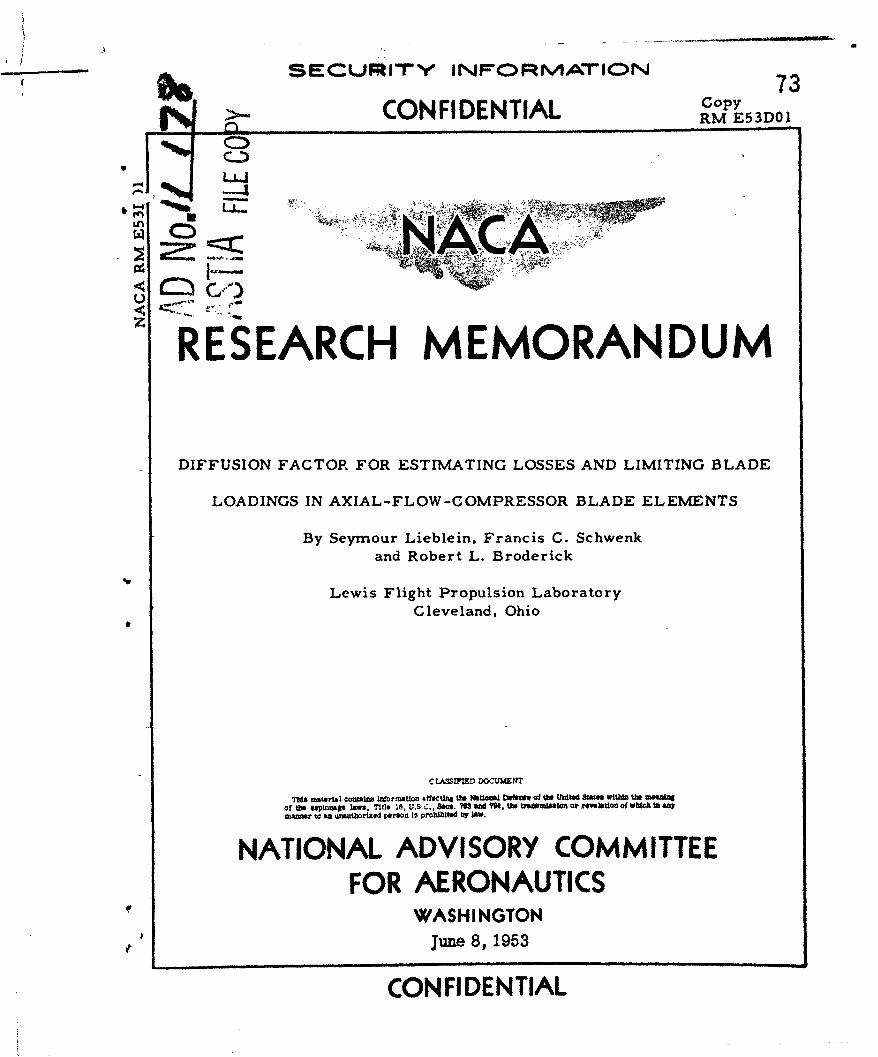
SECLJRiTY INFCIRrMArIO=NCopy 73
CONFIDENTIAL RMoE3Dy
LL.
zRESEARCH MEMORANDUM
DIFFUSION FACTOR FOR ESTIMATING LOSSES AND LIMITING BLADE
LOADINGS IN AXIAL-FLOW-COMPRESSOR BLADE ELEMENTS
By Seymour Lieblein, Francis C. Schwenkand Robert L. Broderick
Lewis Flight Propulsion LaboratoryCleveland, Ohio
C LASSr=E DOCU)EnT
This matertal contab.n WnotnUon offec~ng liD Nk&UO Defense of 00 United States wltta then meaftalof the septogage bws, -I) 25. U.S.C., Secs. 7N3 ad 794, the Utnamieton or revelation of wbich In sNWuiAnnr to an unnwrithled person to proltibited Oy "a.
NATIONAL ADVISORY COMMITTEEFOR AERONAUTICS
41 WASHINGTONJune 8, 1953
CON FIDENTIAL
NACA RM E53DO1 CONFIDENTIAL
NATIONAL ADVISORY COMMITTEE FOR AERONAUTICS
RESEARCH MEMORANDUM
DIFFUSION FACTOR FOR ESTIMATING LOSSES AND LIMITING BLADE
LOADINGS IN AXIAL-FLOW-COMPRESSOR BLADE ELEMENTS
By Seymour Lieblein, Francis C. Schwenk, andRobert L. Broderick
A simplified limiting-blade-loading parameter for axial-flow-compressor blade elements was derived from the application of a separa-tion criterion used in two-dimensional boundary-layer theory to a typi-cal suction-surface velocity distribution of a compressor blade elementat design angle of attack. The derived limiting diffusion factor com-prised a term involving the relative velocity ratio across the blade anda term proportional to the circulation about the element, both of whichcan be evaluated readily from the design velocity diagram.
A correlation was made for the data for NACA 65-series compressorblade sections in low-speed two-dimensional cascade between blade-element loss at design angle of attack and several commonly used andproposed blade-loading parameters. The derived diffusion factor con-stituted a satisfactory limiting-loading criterion for these data.Total-pressure loss coefficient at design angle of attack increasedslightly with diffusion factor up to a value of about 0.6, after whichi a sharp rise in loss was observed. !
Loss coefficient and diffusion correlations were also made for a
large number of conventional experimental axial-flow single-stage com-pressor rotors and stators. For the hub- and mean-radius regions of the
rotors and for the hub, mean, and tip regions of the stators, no consis-tent variation of loss coefficient with diffusion factor was observed inthe low-loss range up to values of diffusion factor of about 0.55 to0.65, the extent of the available data. For the tip region of the rotors,however, there was a very marked and practically linear variation of loss 7coefficient with diffusion factor, with resulting blade-element efficien-cies less than 0.90 for values of diffusion factor greater than about 0.45.Further verification of the limiting relative inlet Mach number of about0.70 to 0.75 for subcritical values of diffusion factor was indicatedfor rotor and stator blades of NACA 65-series profile shapes with about10 percent maximum thickness ratios.
, i- .CONFIDENTIAL
I 2 CONFIDEN~TIAL NACA BM E3OItion INTRODUCTION o
One of the principal limitations and losses in the flow acrossaxial-flow-compressor blade rows is due to the separation of the fric-tion boundary layers on the suction surfaces of the blades. In air-
foil theory, the measure of this limiting blade loading or diffusfbnwas satisfactorily established by the variation of the lift coefficientof the section. (Lift coefficient is defined as lift force per unitblade area divided by inlet or vector-mean dynamic head.) The use of D
lift coefficient as a measure of loss variation and limiting loading*was not, however, generally successful in compressor design application.
Furthermore, the use of lift coefficient for the general compressor caseof compressible flow with unequal axial velocities at blade-elementinlet and outlet presents a difficulty in establishing a significantvector-mean condition. Consequently, various other loading parameterswere tried in compressor design with varying degrees of success. Theseparameters were lift coefficients based on inlet or outlet conditions,solidity multiplied by lift coefficient, ratio of change in tangentialvelocity to axial velocity, ratio of axial velocity to tip speed, and soforth.
In reference 1, Wislicenus proposes an approximate stalling coeffi-cient for axial-flow blades derived from considerations of the stallingsuction-surface pressure distribution of isolated airfoils in incom-pressible flow. The coefficient is developed in terms of vector-meanvelocity and indicates that the stalling pressure rise is a function ofthe sum of the conventional lift coefficient and the over-all change in
free-stream velocity across the blade row. Howell, in reference 2,develops an approximate loading parameter for compressor blade elementsfrom the application of a separation criterion used in boundary-layertheory. This parameter involves the product of the mean-velocity liftdoefficient and a function of the over-all velocity ratio. No extensiveexperimental investigations of these various loading parameters have asyet appeared.
2$ A similar approach to the development of an improved separationcriterion for axial-flow blade elements was made at the NACA Lewis lab-oratory in order to develop a simplified blade-loading parameter basedon boundary-layer theory and independent of lift-coefficient terms.A simplified parameter, called the diffusion factor for design angle ofattack, was obtained by deriving an approximate relation between a
Jseparation criterion used in two-dimensional incompressible turbulentboundary-layer theory (as in ref. 2) and the external velocity diagramand solidity of the blade element. The approximation was facilitated bythe use of a model blade-surface velocity distribution and of the local
- pressure characteristics of blades in two-dimensional cascade at designangle of attack.
CONFIDENTI.AL
NACA RM E53DOI CONFIDENTIAL 3
An experimental correlation between total-pressure loss coefficientat design angle of attack and a large number of proposed separation param-eters is presented for the two-dimensional cascade data of reference 3.In addition, a further correlation between the loss coefficient and thederived diffusion factor is presented for the hub-, tip-, and mean-radiusregions of rotors and stators of a large number of experimental single-stage axial-flow compressors.
tt , SYMBOLS
The following symbols are used in this report:
a ratio of distance from leading edge to point of maximum suction-surface velocity to chord length
b constant in diffusion-factor equation
CD drag coefficient
CL lift coefficient
Cs stalling coefficient of reference 1
c chord length
D diffusion factor
*.- d constant in diffusion-factor equation
F force
FD drag force!D
H boundary-layer form factor (ratio of displacement thickness tomomentum thickness)
i angle of incidence, angle between inlet-air direction and blademean-line direction at leading edge
L lift force
M Mach number
!/| :n constant in separation-criterion equation
SP total pressure
- lW{W~fTA
p1 A
4 CONFIDENTIAL IACA RM E53DO1
p static pressure
q constant
R reaction or recovery ratio
Re momentum-thickness Reynolds number
r radius
s blade spacing CO
T total temperature
t static temperature
V relocity
V circumferentially averaged velocity
Vav average velocity between Vma x and V2
Vma x maximum velocity on suction surface
x distance along flow path
CL angle of attack, angle between inlet-air direction and bladechord
air angle
r' velocity-gradient parameter of reference 2
T ratio of specific heats
I -adiabatic temperature-rise efficiency
e boundary-layer momentum thickness
p static density
a solidity
T shear stress
Wi relative total-pressure loss coefficient, P2,i " P P P1
CONF IDENTIAL
NACA RK E53DO1 CONFIDENTIAL 5
Subscripts:
a axial
i ideal!I
m vector mean
R rotor
S-ref reference
S stator
0 tangential
1 inlet
2 outletIThe prime refers to relative conditions for rotating elements.
ANALYSIS
Approach
Exclusive of three-dimensional effects in the end regions of bladerows, the development of friction boundary layers along the surfaces ofcompressor blade elements is determined primarily by the surface pressuredistributions and therefore by the basic geometry of the element (profileshape, canber, thickness, solidity, and angle of incidence). Therefore,a first approach to the problem of boundary-layer growth and separationcan be made by considering the two-dimensional flow about blade elements.Although several techniques are available for computing boundary-layergrowth in two-dimensional cascades (refs. 4 to 6), they depend on a priorknowledge of the pressure or velocity distribution about the blade sec-tion. However, accurate practical methods of computing compressiblepressure distributions about arbitrary compressor cascade sections arenot as yet available.
In view of the general complexity and incompleteness of currentboundary-layer and pressure-distribution theory, the accurate calcula-tion of the boundary-layer development and total-pressure loss of agiven blade element was not believed to be currently feasible. It wasdecided, therefore, as a first approach, to investigate the possibilityof deriving a simplified and approximate blade-loading or separationcriterion. The approximate separation criterion might then, in conjunc-tion with an extensive experimental correlation, provide a simple anduseful means of determining regions of safe or unsafe limiting designconditions for the actual compressor.
CONFIDENTIAL
6 CONFIDETIAL NACA RM E53DO1
For conventional compressors, in general, differences in bladeshape, boundary-layer Reynolds number, turbulence level, transition fromlaminar to turbulent flow, and Mach number are not very great; so that,comparatively, the most significant factors influencing the pressuredistribution and the loss of a blade element are the angle of incidenceand the circulation about the element. Furthermore, if attention isrestricted to the design point (design angle of incidence), it would beexpected that the basic velocity vector diagram of the element at designwould be the largest factor affecting the loss. The problem is thenreduced to deriving a satisfactory, simplified, and approximate relationbetween the limiting diffusion gradient on the blade suction surface andthe over-all velocity change across the .blade row as determined by thedesign velocity diagram.
Diffusion Factor
A parameter frequently used in establishing a separation criterionin incompressible, two-dimensional, turbulent boundary-layer theory(refs. 2 and 7, for example) is given by
D 2 V Re ()
where e is the boundary-layer momentum thickness, V is the free-stream velocity outside the boundary layer, x is distance along the"1rction of flow, Re is the momentum-thickness Reynolds number, and n
is a constant (negative value). The significance of equation (1) can beseen from inspection of the general momentum boundary-layer equation
de _(H+2) e dV--" - V ddx pV 2 V 2
where T is the viscous shear stress at the surface, H is boundary-layer form factor (ratio of displacement thickness to momentum thick-ness), and p is free-stream density. For configurations with fairlylarge adverse velocity gradients - as in the case for compressor bladesuction surfaces - rapid rates of boundary-layer growth are associatedprimarily with the last term of equation (2) involving the velocity gra-dient dV/dx. In fact, for incipient separation, the shear stress Tapproaches zero, and the form factor H approaches an approximatelyconstant value of about 2.0 to 2.5 (refs. 6 and 7). Equation (2)therefore becomes dO d,
constant (3)
j" CONIDEINTIAL
NACA RM E53DO1 CONFIDENTIAL 7
Equation (3) shows that the first factor on the right side of equa-tion (1) is proportional to the gradient, or growth rate, of the iomen-tum thickness e at the point of incipient separation.
In order to evaluate the importance of the second factor, Ren, inequation (1), it is assumed that for typical velocity distributions,the local value of Re is related to the initial value of Re at the
~start of deceleration. Inasmuch as the flow on the suction surface waspreviously accelerating, the initial value of Re defines the condition
D of ke initial boundary layer (ref. 6). Thus the Ren term in equa-tion (1) reflects the additional effect of the state of the initialboundary ,layer. In general, the greater the magnitude of Re, the
smaller -.he allowable diffusion at separation (refs. 6 and 8).
For conventional compressors - and certainly for a given cascadeinvestigation - the range of variation of initial boundary-layer Reynoldsnumber, as influenced by such factors as blade size, inlet Mach number,
surface roughness, and turbulence level, is generally not large.
The effect of initial boundary-layer Reynolds number can thus berepresented by a constant average value. A simplified separation crite-rion is therefore adopted as the diffusion factor:
D V dV (4)
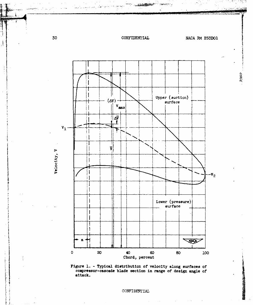
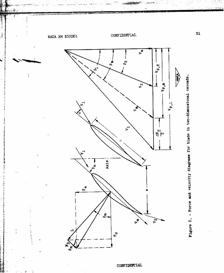
The variation of velocity over the surfaces of a typical compressor bladesection set at its design angle of attack is shown in figure 1, and theelement velocity diagram is shown in figure 2. By design angle of attackis meant the angle of attack at minimum loss. Diffusion of the suction-surface velocity must occur from the peak velocity near the leading edgeVmax to the outlet velocity V2 . (It is assumed that V2 at the blade
trailing edge is equal to the mean V2 considered by the velocity diagramat the downstream measuring station of the blade row.) For most conven-tional blade designs, the velocity generally varies approximately lin-early from Vma to V2 . The diffusion gradient can then be approxi-
mated on the average by
idV Vmax - V2" -V (1-a)cVav
where Vav is some average surface velocity between Vm and V2 .
i The use of equation (5) is expected to be valid for moderately non-linear velocity variations as well, since recent unpublished results ofboundary-layer analyses conducted at the NACA Langley laboratory indi-cate that the over-all diffusion Vmax - V2 is the significant factor
affecting limiting loading.
'_5 : _-L CONFIDENTIAL
a CONFIDEIAL NACA RM E5IDOI
From examination of velocity distributions about typical compressor
blade sections, it was found that the average velocity Vav in thedenominator of equation (5) can be approximated by VI, so that equa-tion (5) can be given by
1ldV 1 E V2 \ (6)
In general, the magnitude of the maximum suction-surface velocity canbe considered to be composed of several components so that, as shownin figure 1,
Vmax V + AV V I + AV + AV (7)
where AV represents the velocity increment due to chordwise variationsof the circumferentially averaged velocity (function of ratio of bladethickness to blade spacing and of inlet Mach number), and AV representithe velocity increment above the value of V that arises from the bladeloading or circulation (function of profile shape and angle of attack).In terms of inlet velocity, equation (7) can be expressed as
Vmax 6 V )
1l + AV+(8)v1 V1 V1
In hypothesizing a functional relation between maximum velocityratio and circulation as indicated in equation (8), use was made of thecharacteristics of blade sections in low-speed, two-dimensional cascade.The similarity of surface pressure distributions for a given blade sec-tion in cascade and in the compressor configuration in the region ofdesign angle of attack is demonstrated in reference 9. From examination
*of the pressure distributions about the NACA 65-series blade sections incascade (ref. 3), it was deduced that a functional relation can beestablished between the velocity ratio and a circulation parameterAVe/oV1 (proportional to lift coefficient) in the form
v-T - b- + d (9)
where d represents the surface-velocity rise due to the effect offinite blade thickness indicated in equation (8). In general, both band d may vary with blade shape, angle of incidence, and inlet Machnumber. If it is then assumed that equation (9) is valid for conven-tional compressor blades, the diffusion parameter D can be expressed as
D (l-c +b- d D + d] (10)
CONFIDEThIAL
.. .. iP mlpw l ? !!i.. .. .... . .--' i !i
. i
I NACA RM E53DOl CONFIDENTIAL 9
If it can further be assumed, for simplicity, that the average ratio ofboundary-layer momentum thickness to chord length, e/c, and the locationratio, a, vary very little for conventional types of blading, then, onthe average
! e(1-a)c constant
and the diffusion parameter can then be reduced to the formO
D = b +d (ii)
Average values of b and d obtained from examination of the dataof reference 3 at design angle of attack were about 0.4 to 0.5 and about0.1, respectively. The design angle of attack for the cascade data wastaken as the value of incidence at the midpoint of the low-loss range.In checking the trend of the effect of compressibility on the value ofb and d obtained from the low-speed data, it was found that, if thelocal pressure coefficient and the circulation parameter both varied inthe same manner with Mach number (say, the Prandtl-Glauert relation),the increases in magnitude of b and d at the design angle of attackup to Mach numbers of about 0.75 would be small. Values of b and dwere consequently taken as 0.5 and 0.1, respectively, to give
D - + + 0.l (12)
Since there are generally small differences in thickness and thicknessdistribution for commonly used blades, the last term in equation (12)will not vary much, and the design diffusion factor D for a compressorblade element is finally established as
$ V 2 \ Ave* D U-T) + (13)
where all velocities are taken relative to the blade.
The suction-surface diffusion is thus seen to be a function of twoprincipal factors: the over-all change in relative velocity across the
i element, and a term proportional to the conventional lift coefficient ofthe section based on inlet velocity
CONFIDENTIAL
10 CONFIDENTIAL NACA RM E53DOI
2AVe cos 01CL,1 V1 cos m
For two-dimensional flow with equal axial velocities at inlet andoutlet, the diffusion factor of equation (13) becomes (see fig. 2)
'1 cos l cos 01- + (tn-2"ta 2 (14)D cos 02o t n 0 - t n 0 )0
The general similarity between the derived design diffusion factorof equation (13) and the stalling coefficient of reference 1 is illus-trated by the expansion of equation (A8) in appendix A with
Vm = (V1 + V2 ) to give
2 [ 2 v.) 2t~ve I(l+v
where q is a constant varying between 1 and 2. The velocity gradientparameter r of reference 2, in contrast, involves a product of thelift coefficient and the over-all velocity-ratio terms (eq. (A9), appen-dix A).
RESULTS AND DISCUSSION
Two-Dimensional Cascade
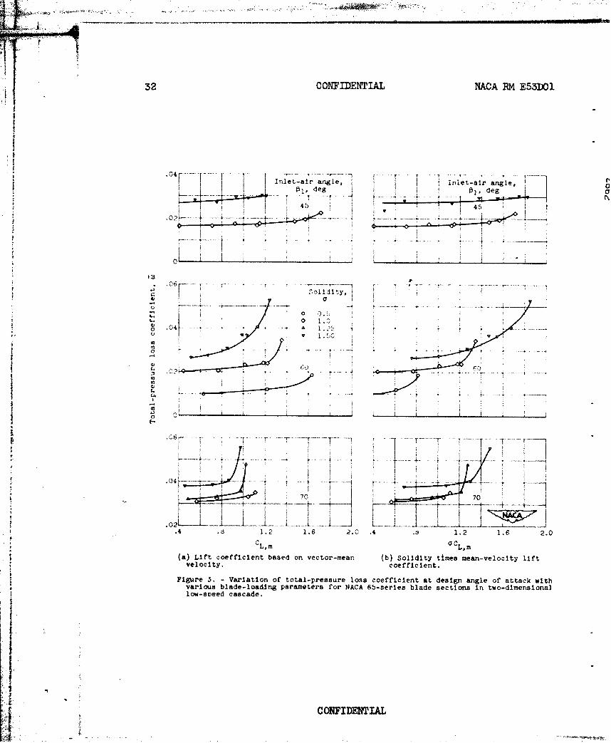
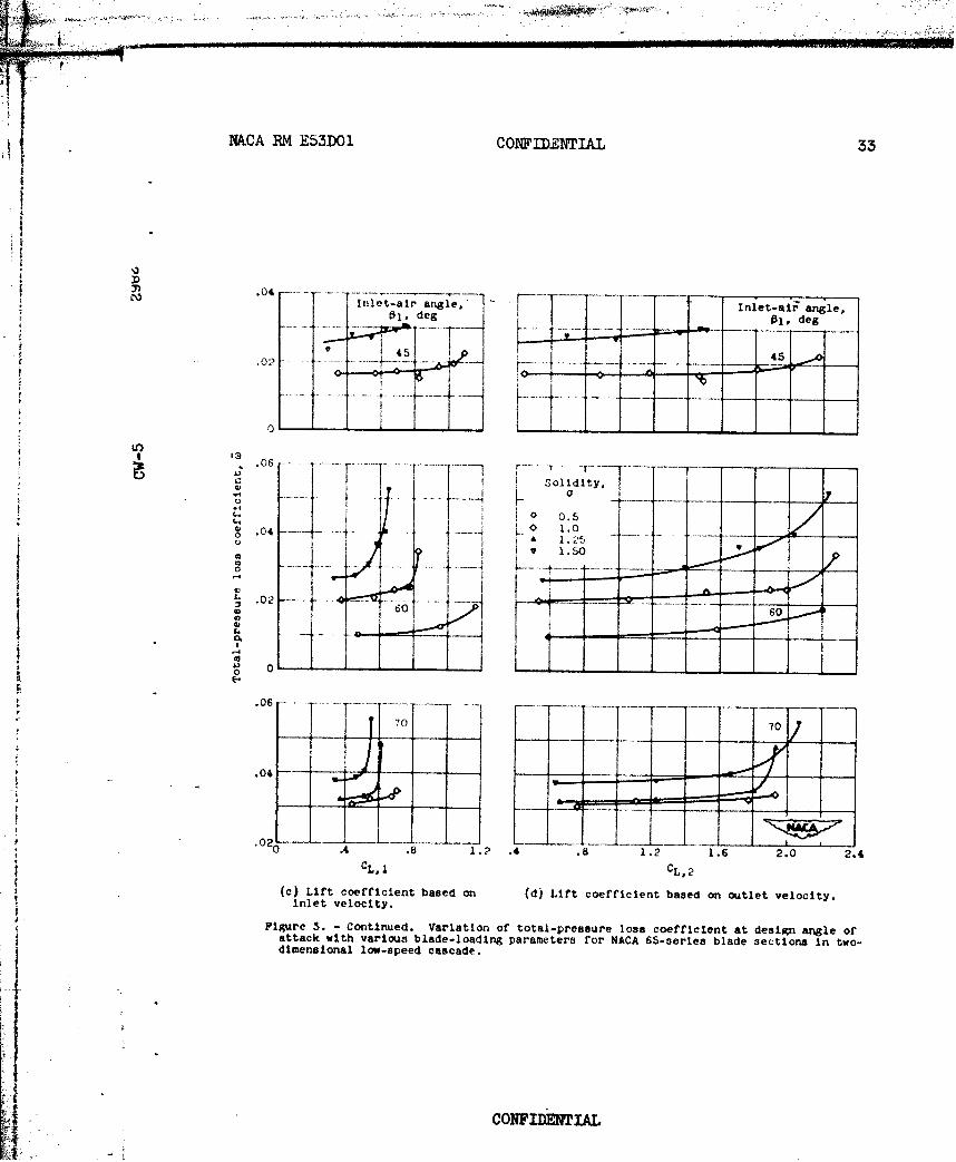
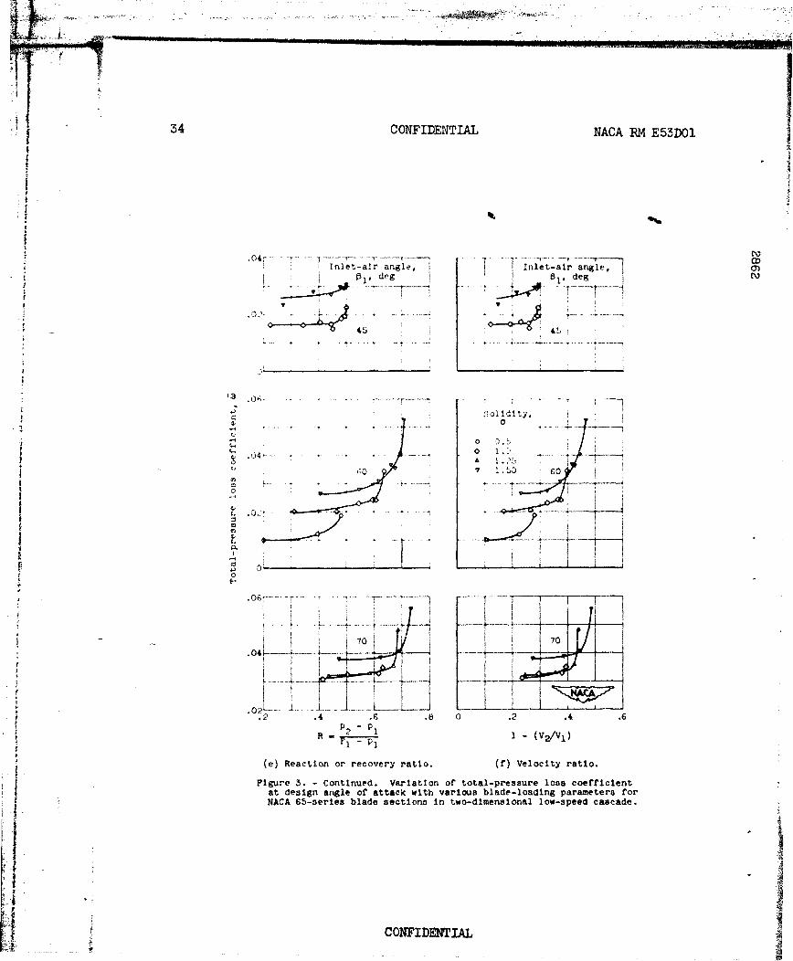
The general validity of the various blade-loading parameters andseparation criteria commonly used in axial-flow-compressor design wasfirst investigated for the extensive low-speed cascade data for the NACA65-series compressor blade sections as given in reference 3. The anal-ysis was made by examining the variation of blade-element total-pressureloss with various loading parameters at design angle of attack. Thetotal-pressure loss was expressed in terms of a loss coefficient 1, asdefined in appendix B. For the cascade data, the total-pressure losscoefficient was computed from the drag coefficients (based on inlet con-ditions) given in reference 3 according to equation (B17) in appendix B.Design angle of attack for the loss evaluation was taken as the midpointof the minimum drag range. Loading parameters considered were: (1)theoretical lift coefficient based on vector-mean velocity, (2) soliditymultiplied by theoretical lift coefficient based on vector-mean velocity,(3) theoretical lift coefficient based on inlet velocity, (4) theoreti-cal lift coefficient based on outlet velocity, (5) over-all reaction orrecovery ratio, (6) relative velocity ratio, (7) velocity-gradient
S.. .CONFIDENTIAL
NACA RM E53DOI CONFIDENTIAL 11
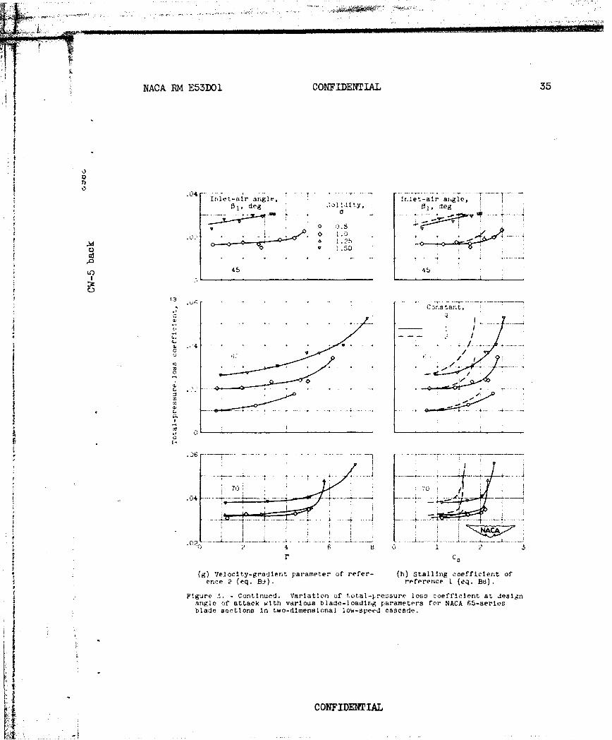
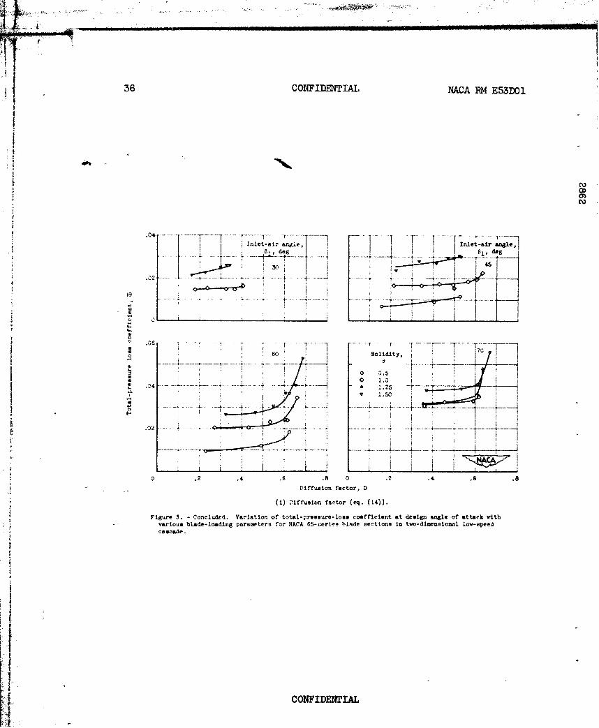
parameter of reference 2, (8) stalling coefficient of reference 1, and(9) diffusion factor given by equation (14). The various theoreticallift-coeffiCient eq~tions and loadiq& parameters are given in appen-dix A. The resulting comparison of total-pressure loss coefficientagainst loading parameter ie shown in figure 3. Each curve in figure 3represents the variation of loss coefficient for the range of cambersused at each fixed condition of solidity and inlet-air angle.
From figure 3 it is seen, as expected, that the loss tends toO increase gradually with increasing blade loading, and that, particularly
at inlet angles of 600 and 700 a sharp rise in loss indicative ofseparation occurs beyond a certain value of the blade loading. For thevarious blade-loading parameters plotted in figure 3, it is seen thatonly the outlet lift coefficient (fig. 3(d)), Howell's gradient param-
Aeter (fig. 3(g)), Wislicenus' stalling parameter (fig. 3(h)), and thediffusion factor D (fig. 3(i)) can be considered as acceptable limit-
4ing criteria.
For Howell's parameter (fig. 3(g)), a limiting value of about 4.5to 5.0 is indicated; and for the stalling coefficient of Wislicenus(fig. 3(h)), the limiting value is about 2.0 for q = 1.0. For thediffusion factor (fig. 3(i)), the point of loss rise occurs at a valueof D of about 0.6. It is interesting to note that one of the morecommon limiting-loading parameters of CCL,m = 1.0 to 1.2 (ref. 10, e.g.)corresponds to the point of loss rise for an inlet angle of about 600 andsolidity from 0.5 to 1.0 (fig. 3(b)), conditions which are closely
fdescriptive of rotor-tip velocity diagrams. This same limit, however,(as was indicated in ref. 3) would not be valid for other conditions ofsolidity and inlet angle for these data.
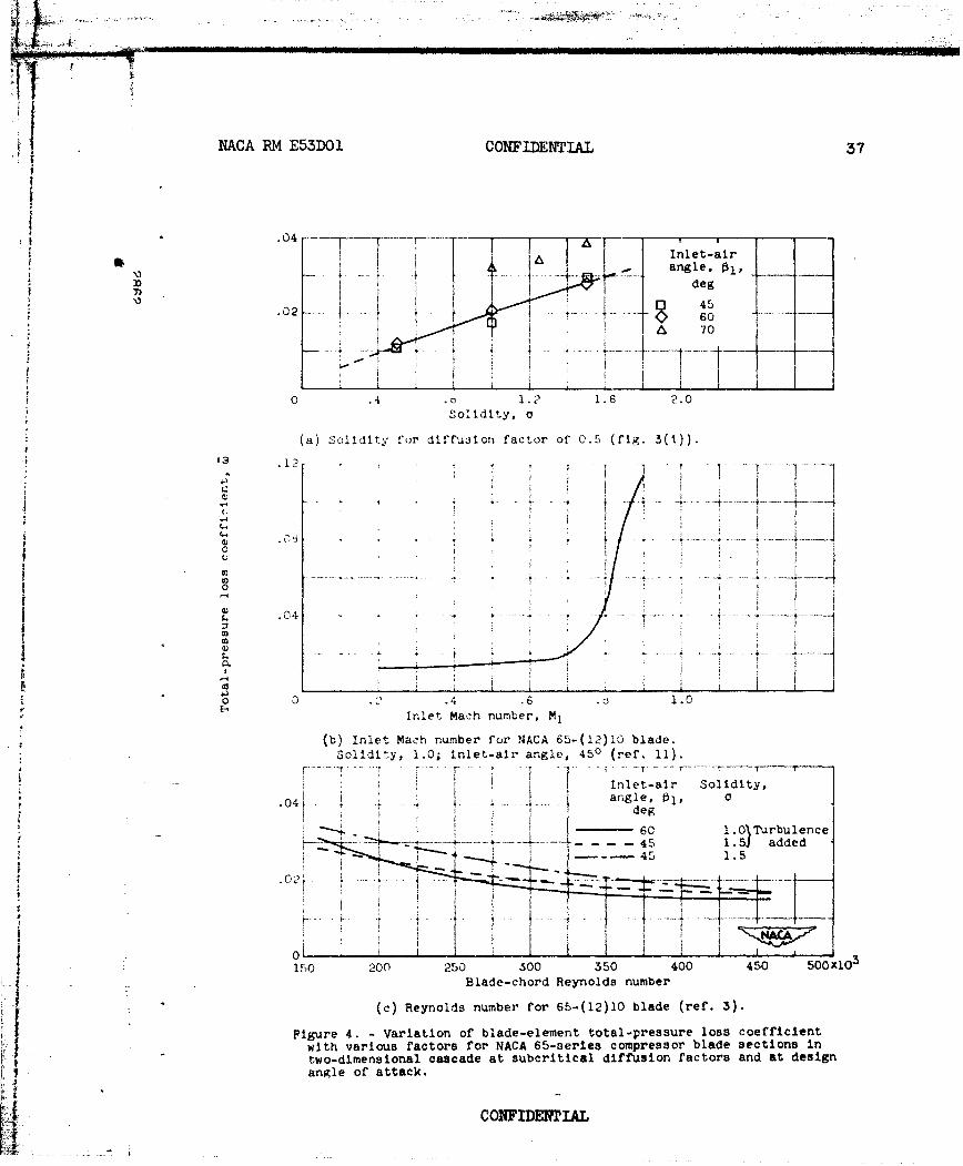
* With the establishment of the diffusion factor as a satisfactoryloading limitation for design blade-element loss, it is interesting toexamine briefly some of the other coexisting factors, such as solidity,inlet Mach number, and Reynolds number, which influence the magnitude ofthe loss. A cross plot of the data of figure 3(i) for subcritical(below limiting value) diffusion factors indicates that the loss coef-ficient varies primarily with solidity and to a smaller extent with inletangle. The loss variation with solidity for D - 0.5 is illustrated infigure 4(a). For the usual range of inlet angles from 400 to 600 it canbe taken roughly that the loss coefficient will vary directly with thesolidity (as a reflection of the increased friction surface), as long asthe critical diffusion rate is not exceeded.
f A second significant factor in blade-element performance is thegeneral compressibility effect and the formation of surface shocks andboundary-layer separation. An illustrative variation of total-pressureloss coefficient with inlet Mach number for a 65-series blade element is
CONFIDENTIAL
jo
12 CONFIDENTIAL NACA RM E55DOI
shown in figure 4(b). The curve was obtained from the data of refer-ence 1T and recomputed in terms of the loss coefficient used in thisreport. The value of inlet Mach number at which the losses tend to risesharply is called the limiting inlet Mach numberk In gaueral, the lim-iting Mach number will vary with diffusion factor., inlet angle., andsolidity.
The effect of blade-chord Reynolds number on loss coefficient is
shown in figure 4(c) for the data of reference 3. In general, the lossis seen to increase with decreasing Reynolds number, but no sharp risein loss is observed for the lowest values of Reynolds number obtained inthe tests.
Thus for the cascade blade, as long as the limiting diffusion factorand limiting inlet Mach number are not exceeded, design blade-elementtotal-pressure loss coefficient will not be excessive for the usualrange of solidity, Reynolds number, and blade shape. The exact selec-tion of the magnitudes of these factors of diffusion, solidity, andReynolds and Mach numbers, of course, will depend on the particulardesign application and such considerations as range of operation, off-design characteristics, size, and three-dimensional effects.
Compressor Rotor
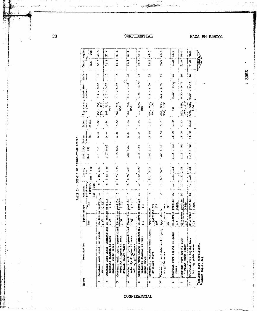
In view of the success of the diffusion factor in establishing aconsistent loading limitation for the 65-series cascade blade, a furtheranalysis was made to ascertain the general validity of the diffusionlimit for blades in the actual compressor configuration. A correlationwas obtained between measured relative total-pressure loss coefficientand calculated diffusion factor across blade elements in the hub, tip,and mean regions of a large number of experimental axial-flow singlestages over a range of tip speeds. A transonic rotor, as well as con-ventional subsonic designs, was included in the comparison. Details ofthe various rotor designs and blade shapes from which the data wereobtained are given in table I.
The diffusion factor was computed according to equation (13) fromthe measured velocities at blade inlet and outlet obtained from radialsurveys. The total-pressure loss coefficient relative to the rotor bladeelement was computed from the measurements of absolute total-pressureratio and total-temperature ratio and the relative inlet Mach numberaccording to the development in appendix B (eq. (B9)). For the bladerows with varying hub radius, the inlet and outlet flow conditions weretaken along approximated streamlines, and the solidity term in equa-tion (13) was taken as an average value. The effect of the ideal rel-ative total-pressure ratio (eq. (B4)) on the computed loss coefficient(eq. (B3)) was negligible for the range of wheel speed and change in
A CONFIDNTAL
NACA RM E53DO CONFIDENTIAL 13
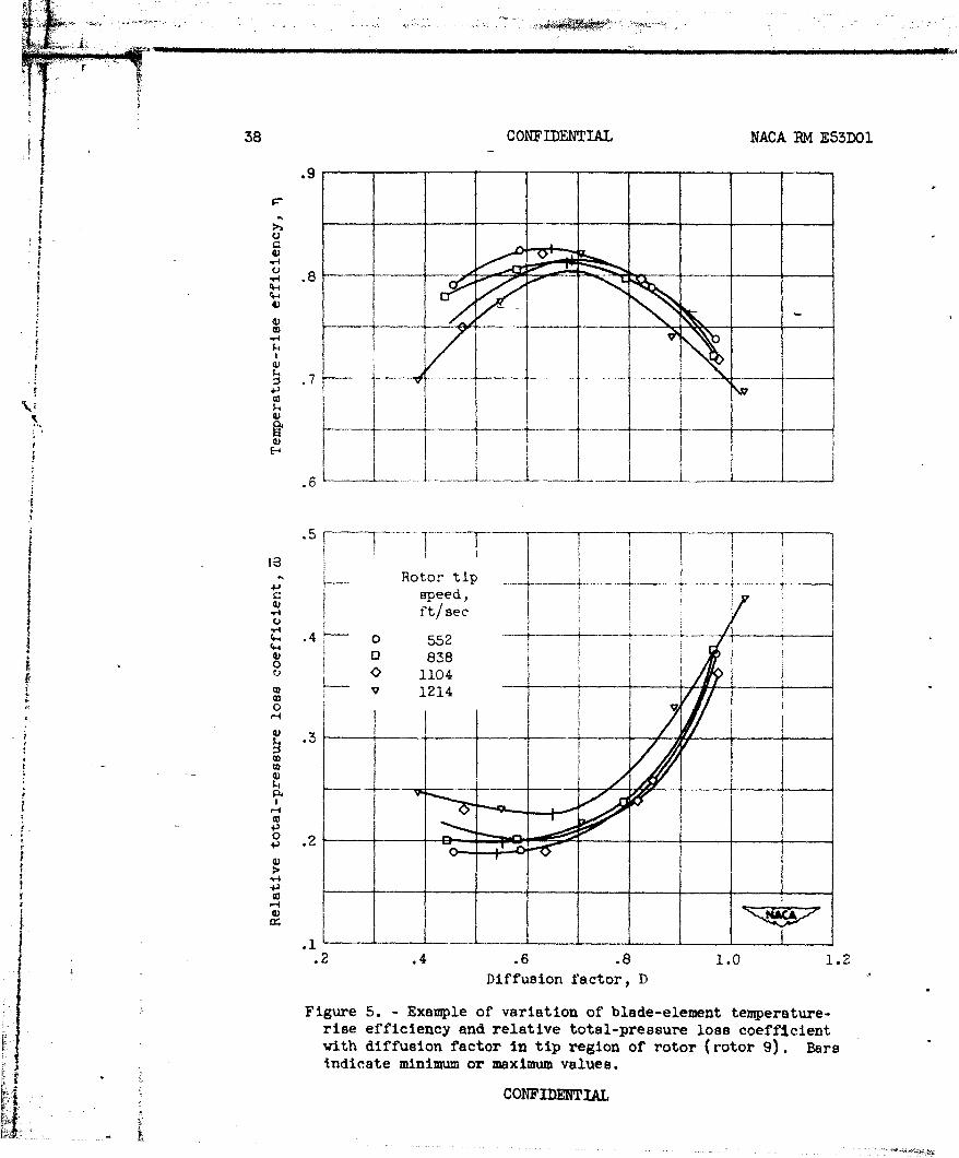
radius of the streamline flow of the stages investigated. Data for theblade-end regions were taken at points from 10 to 12 percent of thepassage height from the outer wall for the tip region, and from 10 to16 percent of the passage height from the inner wall for the hub region,depending on the particular survey program of each compressor. In allcases these tip and hub locations were outside the wall boundaryregions. In order to obtain data representing the design angle ofattack, plots of blade-element relative loss coefficient (and efficiency)against diffusion factor were made for each tip speed run as illustrated
, in figure 5, and the point of minimum loss was determined from theW faired curves.
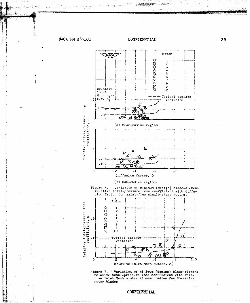
Hub- and mean-radius regions. - The variation of minimum relativetotal-pressure loss coefficient with diffusion factor at the mean- andhub-radius regions of ten single-stage rotor configurations is presentedin figure 6 for sub-limiting relative inlet Mach numbers. In the figureare also shown (dotted lines) the expected variation of loss coefficientbased on cascade characteristics for average conditions of solidity andinlet angle (a m 1.2, - 500 for mean; and a - 1.5, j- 400 for
hub) at inlet Mach numbers of 0.1 and 0.75. The values of loss at thelow Mach number were obtained from the data of reference 3, and thevalues of loss at the high Mach number were obtained from the use ofratios of compressible loss to incompressible loss as determined fromfigure 4(b). For the hub- and mean-radius regions, no marked variation
jof loss coefficient with diffusion factor is found, with a large accu-mulation of points between a loss of zero and about 0.1 up to a diffu-sion factor of about 0.6.
It is seen that quite a few points are obtained both below andabove the anticipated loss levels for blade-element flow as deduced fromthe cascade data. Aside from possible differences in solidity, bladeshape, and Reynolds number, the data points above the upper cascade limitcan be attributed to three-dimensional and unsteady-flow effects in therotating blade row or to experimental error. In view of the many pointsat zero or close to zero loss, a good deal of the scatter is suspectedto be the result of experimental error. Small inaccuracies in measure-ments and in determining the correct streamline locations at inlet andoutlet can result in significant errors in the loss determination. Forexample, an error of 10 F in outlet temperature at a pressure ratio of1.20 will result in computed loss values of from 0.011 to 0.050 for atrue efficiency of 0.95 and from 0.042 to 0.082 for a true efficiency of0.90. At an efficiency of 0.90 and a pressure ratio of 1.4, the spreadf of the loss error is somewhat smaller (0.033).
In view of these considerations, the rotor data of figure 6 for huband mean regions are interpreted as an adequate confirmation of the lossI trend with diffusion factor as established from the cascade data up to
CONFIDENTIAL
14 CONFIDENTIAL NACA RM E53DOI
values of at least about 0.55. Unfortunately, values of diffusion fac-
tor greater than about 0.55 were not obtained in the tests, so that acomparison of limiting values of diffusion factor could not be made. Itappears, however, that no difficulty with limiting loading or separationshould be experienced in the hub- and mean-radius regions of the rotorfor design diffusion factors up to about at least 0.55, provided thelimiting relative inlet Mach number for the particular blade profile isnot exceeded.
Further confirmation of an inlet Mach number limitation in the com-pressor configuration was observed for the NACA 65-series rotor bladesof about 10 percent maximum thickness at the mean radius, as shown bythe loss-coefficient plots of figure 7. The dashed line indicates theexpected loss variation as obtained from cascade tests (ref. 11). Amarked rise in loss is observed for relative inlet Mach numbers greaterthan about 0.7 to 0.75. The diffusion factors of the data points at thehigh Mach number values were less than 0.6. (These high Mach numberpoints were not included in the plot of fig. 6(a).) A similar compress-ibility effect for the hub region could not be definitely establishedbecause of the generally lower levels of inlet Mach numbers in thisregion. It can reasonably be assumed, therefore, that, for the conven-tional NACA 65-series blades of 10 percent thickness ratio, Mach numberdifficulties will be avoided (for subcritical diffusion factors) at hub-and mean-radius regions of the rotor if the relative inlet Mach numberdoes not exceed a value of about 0.7 to 0.75. For other types of bladeand thickness variations, of course-, the limiting Mach number range willbe different.
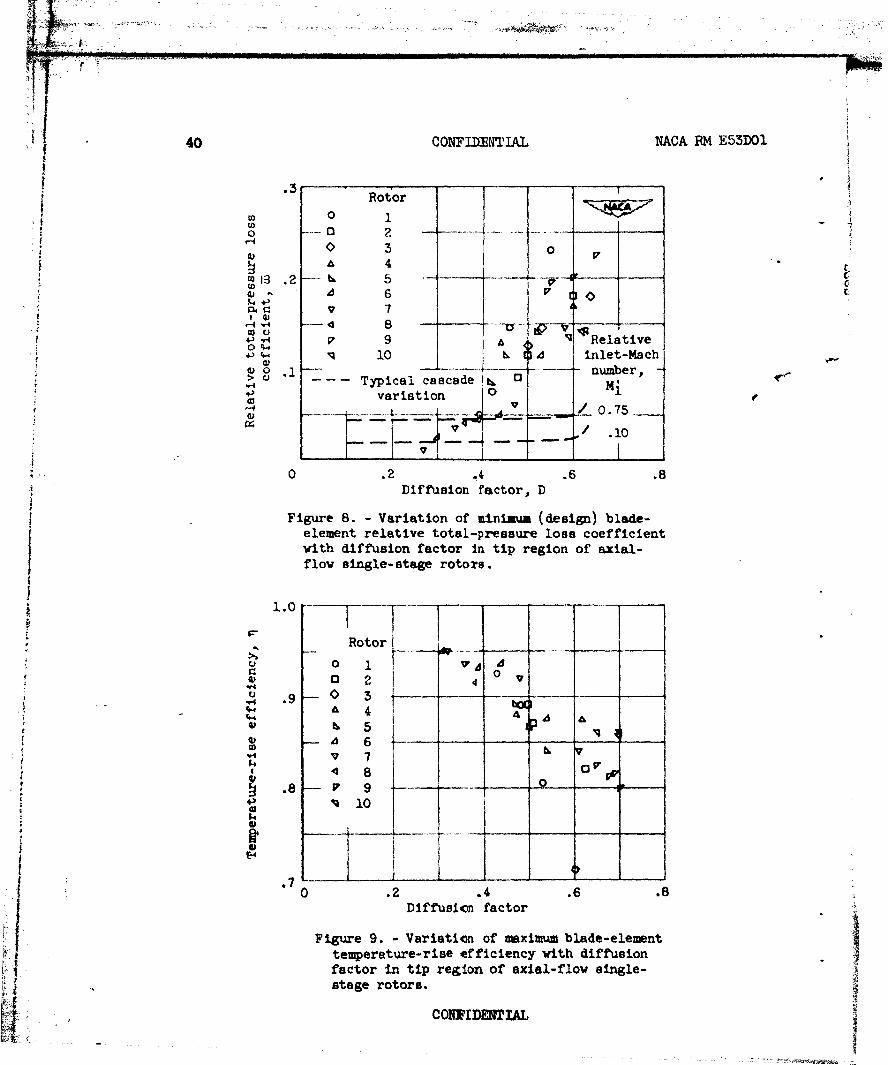
Tip region. - The variation of minimum (design) relative total-pressure loss coefficient with diffusion factor in the tip region of therotor is shown in figure 8. As before, the dashed lines represent therange of loss indicated by the cascade data (a - 0.9, { m 600). Inmarked contrast to the hub- and mean-radius correlations, the tip-regionplot shows a greater range of loss values and diffusion factor with avery definite and essentially linear increase in loss coefficient withdiffusion factor. The trend of the loss variation below values of Dof 0.3 could not be established because of insufficient data. It isexpected that the loss coefficient will remain approximately constant asthe diffusion factor approaches zero. The corresponding variation ofmaximum blade-element temperature-rise efficiency with diffusion factoris shown in figure 9. For a tip-region efficiency of 0.90, diffusionfactors no greater than approximately 0.45 are indicated.
The early deterioration of the flow in the rotor tip region isbelieved to be the result of tip losses and three-dimensional effectssuch as clearance leakage, casing boundary-layer growth and scrubbing,secondary flows, and radial displacement of low-energy fluid out towardthe rotor tip. Exactly which factors or combination of factors con-tributes most to the premature rise in loss is not presently known andLi C0NFIDMIIAL
NACA RM E53D01 CONFIDENTIAL 15
should constitute an important aspect of future research. In view ofthe fact that the flow in the tip region is not a "blade-element" orprofile flow) the strength of the tip-region correlation with diffusionfactor suggests that the local (or over-all) static-pressure gradientsthat exist in the blade-end regions (imposed by the blade element) playan important role in the complex tip-loss phenomena.
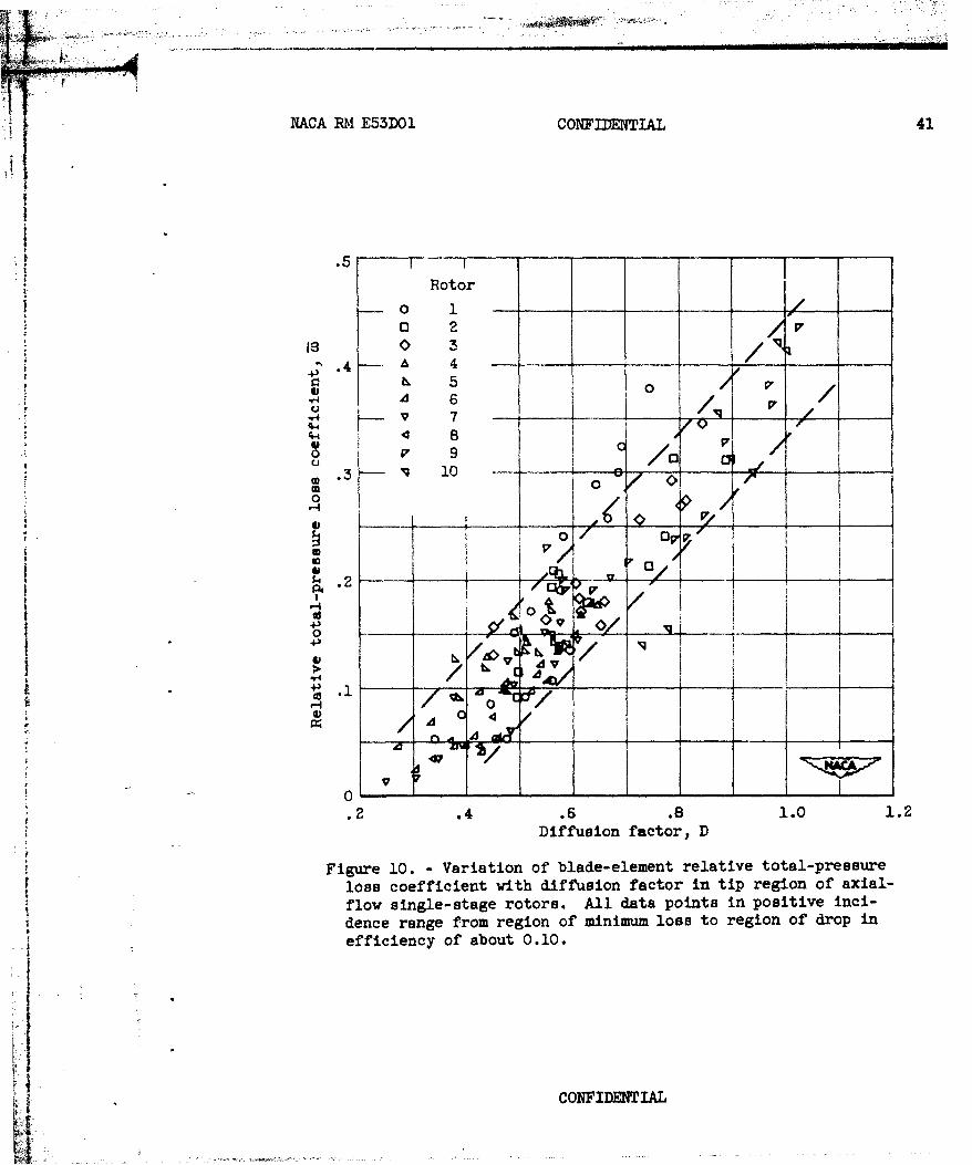
It was also observed that a correlation between loss coefficientand diffusion factor can be obtained for all loss values in the posi-tive range of angle of incidence (increasing diffusion factor) from theregion of minimum loss coefficient to values corresponding to a decreasein efficiency of about 0.10 to 0.15 (see fig. 5(a)). The resulting plotis shown in figure 10. The correlation of figure 10 results from thefact that the average slope of the variation of loss against diffusionfactor in the positive incidence range (see fig. 5) is roughly equal tothe slope of the original plot of minimum loss coefficient (designincidence angle) against diffusion factor shown in figure 8. The dataof figure 10 may find use in estimating tip-region losses at positiveincidence (low weight flow) off-design conditions.
In figure 8, for the rotors with 65-series blade shapes, only thetwo highest loss points of rotor 1 were at relative inlet Mach numberssubstantially greater than the limiting values indicated in figure 7.The effect of inlet Mach numbers above the limiting values is markedlyshown in the efficiency plot of figure 9 and in the loss plot of fig-
ure 8. Theoretically, the general plots of loss coefficient againstdiffusion factor as derived herein would be expected to be a family ofcurves with relative inlet Mach number as parameter. Within the limitsof experimental accuracy, a correlation of experimental loss data interms of diffusion factor may provide a means for separating the indi-vidual loss contributions arising from blade loading (conventionalsurface-velocity gradients) and shock effects (boundary-layer inter-action and wave formation).
The scatter of the data in figures 8 and 9 is attributed primarilyto differences in tip losses, in the locations of the tip-region surveystations (efficiency gradients are large in this region), and to exper-imental inaccuracies. For example, for a pressure ratio of 1.2 at atrue efficiency of 0.85, an error in outlet temperature of ±10 F resultsin total-pressure loss values of 0.079 to 0.138. As an alternate methodwhich circumvents the direct use of temperature-rise efficiency) therelative total-pressure loss can be determined from the computed rela-tive total-pressure ratio as indicated by equations (B2) and (B6).However, experimental inaccuracies are likely to be encountered in thisprocedure, also.
It was impossible to evaluate the relative significance of the two
contributing terms (the velocity ratio and the circulation parameter)
SCONFIDENTIAL
16 CONFIDENTIAL NACA RM E53DOI
in the diffusion factor, as there was no consistent variation betweenthe terms or dominance of one term over the other. At least for thecascade (as indicated by figs. 3(f) and (i)), both terms appear to beabout equal]Z significant. The value of 0.5 taken for the constant bin the circulation term of eqjtion-(ll) appears to be quite satisfactoryin view of the resulting correlation.
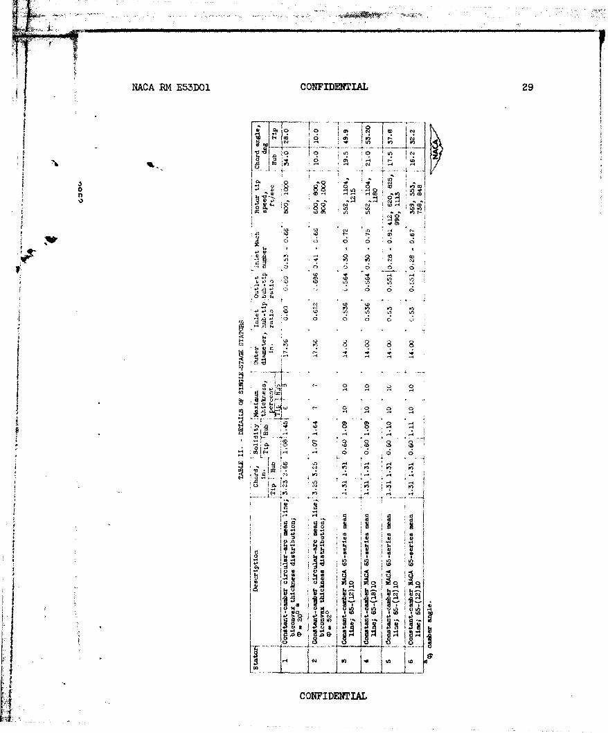
Compressor Statorco
Loss and *iffusion characteristics at design angle of attack forcompressor stator blades were also investigated by examining the datafrom six inlet-stage stator rows, four with NACA 65-series profiles andtwo with double circular-arc profiles. Details of the blade designs aregiven in table II. Stator total-pressure loss coefficient was deter-mined from area averages of the circumferential variation of total pres-sure across a blade spacing as obtained from total-pressure rakes locateda short distance downstream of the stator trailing edge. The loss pre-sented is the total-pressure defect due to the blade wake and does notinclude any possible drop in free-stream total pressure across the statorrow. This total-pressure drop was difficult to establish with any degreeof acceptable accuracy. Data for the tip region were obtained from loca-tions at 9 to 15 percent of the passage height from the outer wall and at13 to 16 percent away from the inner wall for the hub. Velocities wereobtained from inlet and outlet surveys of pressure and angle. In mostcases, only a single midspacing survey was made behind the stators.Plots of total-pressure loss coefficient and diffusion factor against
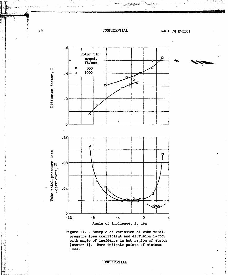
jangle of attack (or incidence) were made as illustrated in figure 11, ande values of w and D were taken at the point of minimum loss (design
angle of attack).
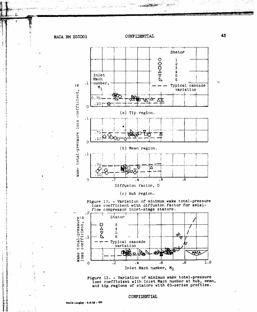
The variation of minimum loss coefficient with diffusion factor forcompressor stators over a range of inlet Mach numbers (rotor tip speeds)is shown in figure 12 for hub, mean, and tip regions. Minimum lossvalues were not attained in the hub and mean regions at some tip speedsfor stator 4, because the data were insufficient to define the loss var-iation over a wide enough range of incidence angle. All points shownare at values of inlet Mach number below the limiting value. The dashedlines, as before, represent the estimated limits bared on cascade per-formance. (There is very little difference between the minimum blade-element loss for 65-series and circular-arc blade profiles.) In allthree regions, no trend of variation of loss coefficient with diffusionfactor is observed, with all points falling between 0.01 and 0.05 up tothe highest diffusion factors obtained (about 0.6).
A cross plot of minimum loss coefficient against inlet Mach number
for all three positions is shown in figure 13 for the stators with NACA65-series profiles of 10 percent maximum thickness ratio. As in the case
CONFIDENTIAL
'I
NACA RM E53DO1 CONFIDENTIAL 17
of the rotor mean-radius region (fig. 7), a rise in loss for inlet Machnumbers greater than about 0.70 is indicated. The high Mach numberpoints in figure 13 were at values of diffusion factor less than 0.65.On the basis of the limited information available, it is expected thatvery low stator losses will occur at design angle of attack, if thedesign diffusion factors -do not exceed about 0M and if the limitinginlet Mach number for the particular blade profile is not exceeded(about 0.70 to 0.75 for the 65-series blade of about 10 percent maximumthickness ratio).
COW Inasmuch as the data for the preceding analyses have been obtained
from a two-dimensional cascade and compressor single stages, the derivedlimiting values and variations will be most valid in the design of theinlet or early stages of a multistage compressor. It is not known towhat extent these values can be applied to the later stages where hub-tipratios are large and where three-dlmensional effects become more pro-nounced. It is also to be noted that the correlations were based onactual measured values rather than on original design values of inlet andoutlet velocity. However, if the general design control and methods offlow prediction are good, the derived limiting values can be directlyapplied as design limits. in this respect, the inlet stages again arein a favorable position, inasmuch as design control is usually best forthe early stages.
SUM4ARY OF RESULTS
A simplified limiting-blade-loading criterion called the diffusionfactor for axial-flow-compressor blade elements was derived from theapplication of a separation criterion used in two-dimensional boundary-layer theory to the blade suction-surface velocity distribution of acompressor blade element at design angle of attack:
1. From a correlation between minimum blade-element total-pressureloss coefficient and a large number of blade-loading criteria commonlyused or proposed for compressor design, it was found that, on the basisof the data for the NACA 65-series compressor blade sections in low-speed., two-dimensional cascade:
a. The derived diffusion factor provided a satisfactorylimiting-loading parameter for the NACA 65-series compressor blade sec-tions, in that the limiting value was clearly defined and was independentof solidity or inlet-air angle. At given solidity and inlet-air angle,the total-pressure loss coefficient at design angle of attack increasedslightly with increasing diffusion factor up to a value of diffusionfactor of about 0.6, after which a rapid rise in loss was observed.
f-I
A r-
18 CONFIDENTIAL NACA RM E53DO1
4
b. The stalling coefficient of Wislicenus and the velocity-gradient parameter of Howell were also adequate limiting-loading param-eters.
2. From a correlation between minimum blade-element relative total-
pressure loss coefficient and derived diffusion factor for data fromseveral experimental single-stage axial-flow compressors at sub-limiting inlet Mach numbers, it was found that:
(0
a. For the hub- and mean-radius regions of ten rotor bladerows, the plot of minimum relative loss coefficient against diffusion
factor showed essentially no significant variation of loss coefficientwith diffusion factor up to values of diffusion factor of about 0.55,which was the extent of the available data.
b. In contrast to the rotor hub and mean regions, the loss
correlation for the tip region of the rotors revealed a very marked andpractically linear variation of loss coefficient with diffusion factorfor values of diffusion factor greater than about 0.30. For a tip-regionefficiency of 0.90, diffusion factors no greater than approximately 0.45
were indicated.
c. For the hub-, tip-, and mean-radius regions of six statorblade rows, the plot of minimum total-pressure loss coefficient egainstdiffusion factor revealed no variation of loss coefficient with diffusionfactor up to values of about 0.60, which was the extent of the availablestator data.
d. Further verification of a limiting relative inlet Mach num-ber of about 0.70 to 0.75 at subcritical values of diffusion factor forNACA 65-series profile shapes of about 10 percent maximum thickness ratiowas indicated.
Lewis Flight Propulsion Laboratory
National Advisory Committee for AeronauticsCleveland, Ohio
CFEI
Ij CONFIDENTIAL
I"NACA R( E5 .DOl CONFIDENTIAL 19
APPENDIX A
LOADING PARAMETERS FOR TWO-DIMENSIONAL INCOMRMSSIBLE FLOW
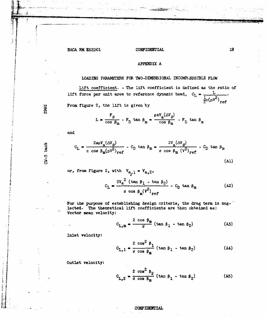
Lift coefficient. - The lift coefficient is defined as the ratio ofLlift force per unit area to reference dynamic head, CL L
1 2)2(PV )ref
From figure 2, the lift is given byCD
Fe psV(AV)L - F tan A a e -F tangcos m FD m cos m D m
and
2BpVa(AV ) 2Va(AVe)CL CD tan m Cos AM C tan
c COSr M(PV-)ref 2)tn
(Al)
or, from figure 2, with Va -Va, 2 ,
2Va2 (tan Al tan 2 )CL -%tan 0 m (A2)
O cos m( )ref
For the purpose of establishing design criteria., the drag term is neg-lected. The theoretical lift coefficients are then obtained as:Vecta mean velocity:
2 Cos A
IInlet velocity:
: Z cos 2 iC o'. - CL' " cos8m tan i"tan p ) (A4)
CL,1 a Cos AMA4
Outlet velocity:! .2 Cos P4 2con
2
C ,Z a cos Am (t anl 1 ) (A5)
COif.~TA
20 CONFIDENTIAL NACA R14 E53DOl
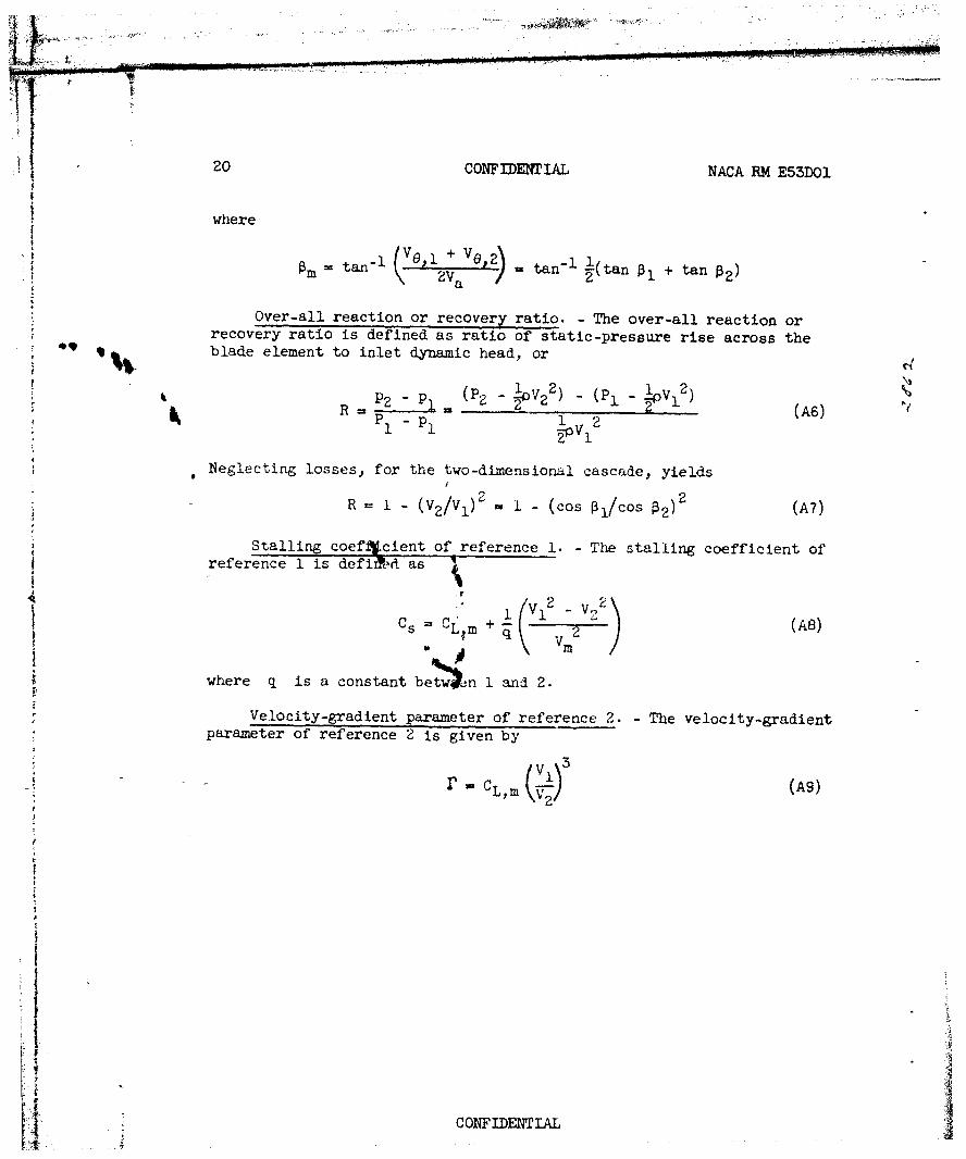
where
v+ VOo= tf~ ' o2 tan 1 :--(tan 3]+ tan
Over-all reaction or recovery ratio. - The over-all reaction orrecovery ratio is defined as ratio of static-pressure rise across theblade element to inlet dynamic head, or
1 2 (21 p1 2p
Neglecting losses, for the two-dimensional cascade, yields
R -1 - (V2 /Vl 2 1 - (Cos P1 /cos 02)2 (A7)J
Stalling coefi~cient of reference 1. - The stalling coefficient ofreference 1 is defir~ct as
Cs =CL m + (A8)
where q is a constant bewn I and 2.
Velocity-gradient parameter of reference 2. -The velocity-gradientparameter of reference 2 is given by
(\3
- L,m ~(s
CONFIDENTrIAL
NACA RM E53D01 CONFIDENTIAL 21
APPENDIX B
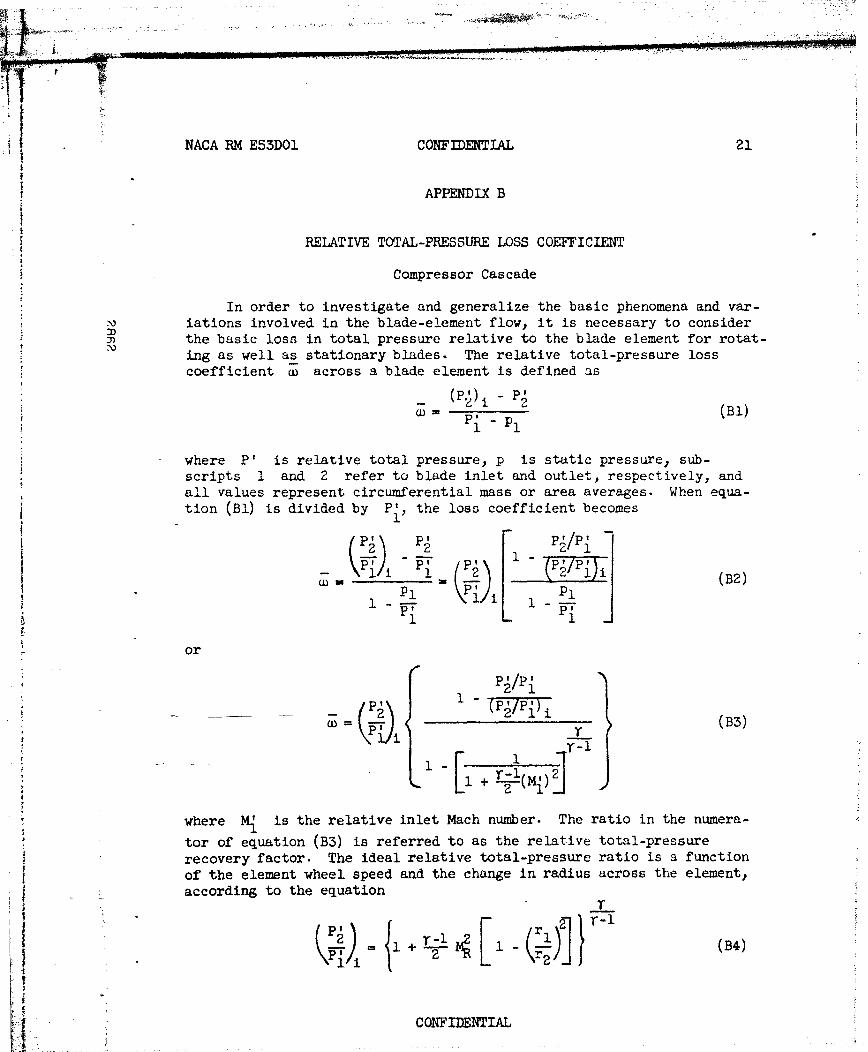
RELATIVE TOTAL-PRESSURE LOSS COEFFICIENT
Compressor Cascade
In order to investigate and generalize the basic phenomena and var-iations involved in the blade-element flow, it is necessary to considerthe basic loss in total pressure relative to the blade element for rotat-
ing as well as stationary blades. The relative total-pressure losscoefficient c across a blade element is defined as
-- (Bl)
where P' is relative total pressure, p is static pressure, sub-scripts 1 and 2 refer to blade inlet and outlet, respectively, andall values represent circumferential mass or area averages. When equa-tion (Bl) is divided by P{, the loss coefficient becomes
(P2 P l P J/P1
P1 1--
or
P /Pi
wK ( r)(B3)r-1
+-[ 2 jJ
* where M{ is the relative inlet Mach number. The ratio in the numera-
tor of equation (B3) is referred to as the relative total-pressurerecovery factor. The ideal relative total-pressure ratio is a functionof the element wheel speed and the change in radius across the element,according to the equation
CILP1 'BI,
gCONFIDENTIA
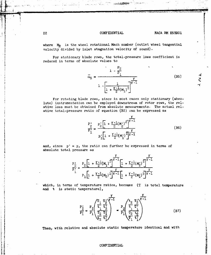
22 CONFIDENTIAL NACA RM E53DOI
where MR is the wheel rotational Mach number (outlet wheel tangential
velocity divided by inlet stagnation velocity of sound).
For stationary blade rows, the total-pressure loss coefficient isreduced in terms of absolute values to
P1 -
Ws (B5) C4
1- 21-1 + (lFor rotating blade rows, since in most cases only stationary (abso-
lute) instrumentation can be employed downstream of rotor rows, the rel-ative loss must be obtained from absolute measurements. The actual rel-ative total-pressure ratio of equation (B2) can be expressed as
1~ + -T
2 + r 2(B6)
and, since p' = p, the ratio can further be expressed in terms ofabsolute total pressure as
SP,[l +r_. +._r_
1 P[ + (M2 ) j + r-!(Mi)
which, in terms of temperature ratios, becomes (T is total temperatureand t is static temperature),
T Tir-, t T' 11 2 2 2
=2 12 2 a. 1 (B7)
(t ;I I/
Then, with relative and absolute static temperature identical and with
.',: i CONFIDENTIAL#;o- .,
r
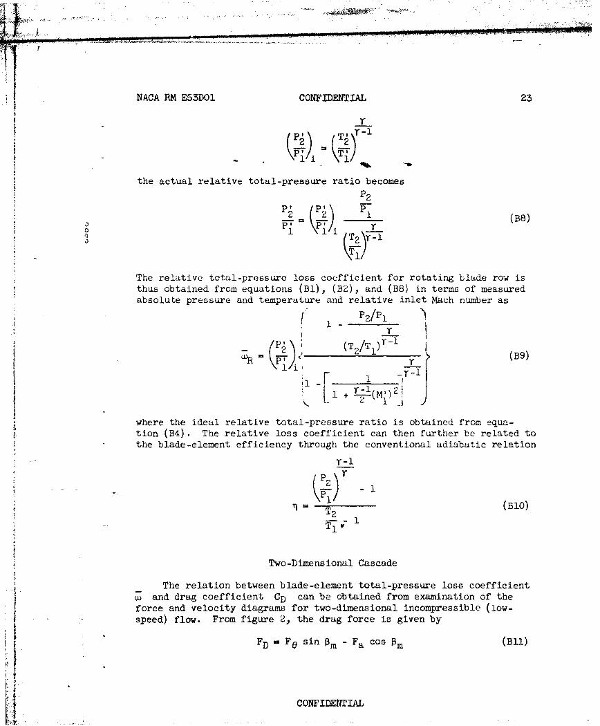
NACA RM E53DOI CONFIDENTIAL 23
r
the actual relative total-pressure ratio becomesP2
2 H) 1 (BB)
i i F T-
ii'2
The relative total-pressure loss coefficient for rotating blade row isthus obtained from equations (Bl), (K2), and (BB) in terms of measuredabsolute pressure and temperature and relative inlet Mach number as
r-__!l
P (T/Tr-
P1 2 (B9)
where the ideal relative total-pressure ratio is obtained from equa-tion (B4). The relative loss coefficient can then further be related tothe blade-element efficiency through the conventional adiabatic relation
-2
ST 2 (BlO)
* Two-Dimensional Cascade
The relation between blade-element total-pressure loss coefficientwand drag coefficient CD can be obtained from examination of the
force and velocity diagrams for two-dimensional incompressible (low-speed) flow. From figure 2, the drag force is given byj "FD Fe sin Pm - Fa cos Pm (Bll)
CONFIDENTIAL
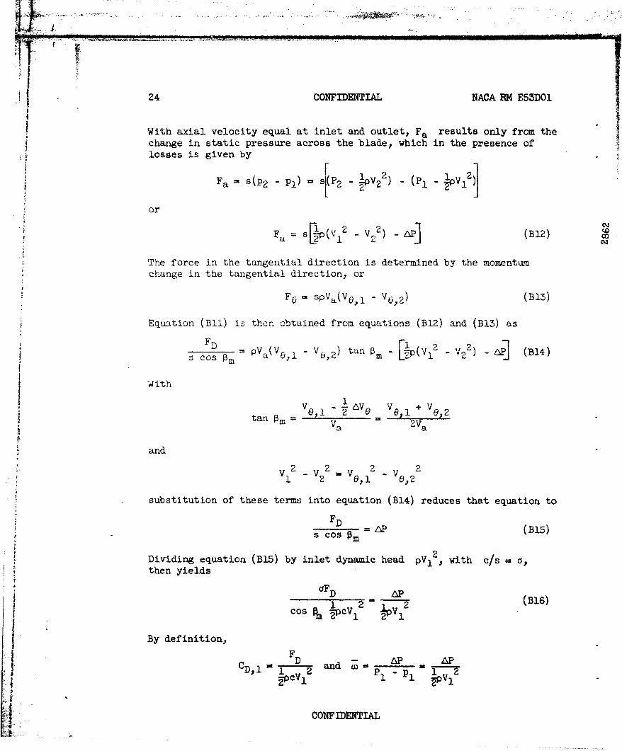
1 24 CONFIDENTIAL NACA RM E53DOI
With axial velocity equal at inlet and outlet, Fa results only from thechange in static pressure across the blade) which in the presence of
losses is given by
2 (P1 - 2a= s(P2 pl ) s[P 2 _- 2 1
or
a= s[- - (B12) c
The force in the tangential direction is determined by the momentumchange in the tangential direction, or
F0 = spVa(V0 ,l - V0,6 2) (B13)
Equation (Bil) is then obtained from equations (B12) and (B13) as~F
D
WiCos Om= PVa(V0,1 - V, 2 ) tan Om- [ (VI2 - V22 ) -P] (B14)
I With
9,1 V +Vtan Pme= v, -2 0 a v0,2= Va = 2a
and
V1 2 2V2 2 V ,1z V, 2
substitution of these terms into equation (B14) reduces that equation to~F D = Cos 6 P (B15)
Dividing equation (B15) by inlet dynamic head V with c/s = a,
then yields
1 (B16)
cos Pm *-PcV 1
By definition,
FCD and 6P AP
cV1 PI 1
4CONFIDENTIAL
!NAOA RM E53DO1 CONFIDENTIAL 25
U
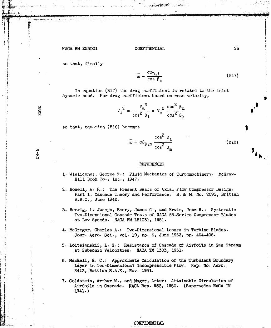
Sso that, finally
! _CI (B17)
W, Cos OM
~In equation (BI7) the drag coefficient is related to the inlet~dynamic head. For drag coefficient based on mean velocity,-
SVl az 2 c0s2 om
IfD
V1 = 2 Vm 2
~so that, equation (B16) becomes
W = C~ (B18); , Cos Om
I REFERENCES
I
I. Wislicenus, George F. : Fluid Mechanics of Turoomachinery. McGraw-I Hill Book Co-, Inc., 1947.
II
~2. Howell, A. R. : The Present Basis of Axial Flaw Compressor Design.~Part I. Cascade Theory and Performance. R. & M. No. 2095., British~A.R.C., June 1942.
3. Herrig, L. Joseph, Emery, James C., and Erwin, John R. : SystematicTwo-Dimensional Cascade Tests of NACA 65-Series Compressor Bladesat Low Speeds. NACA RM LI IA, 1951.
4. McGregor, Charles A.: Two-Dimensional Losses in Turbine Blades.
Jour. Aero. Sci., vol. 19, no. 6, June 1952, pp. 404-408.
5. Loitsiansklii, L. G. : Resistance of Cascade of Airfoils in Gas Stream&ynat Subsonic Velocities. NACA TM 1r03o 1951.
6. Maskell, E. C. : Approximate Calculation of the Turbulent BoundaryLayer in Two-Dimensional Incompressible Flow. Rep. No. Aero.342"31 British R.A.E., Nov. 1951.
" 7. Goldstein, Arthur W., and Mager., Artur: Attainable Circulation of~Airfoils in Cascade. NACA Rep. 953, 1950. (Supersedes NACA TN" 21941.2)
CONFCOB Tm
26 CONFIDENTIAL NACA RM E53D01
8. Donaldson, Coleman du P., and Lange, Roy H.: Study of the PressureRise Across Shock Waves Required to Separate Laminar and TurbulentBoundary Layers. NACA TN 2770, 1952. (Supersedes NACA RM L52C21.)
9. Westphal, Willard R., and Godwin, William R.: Comparison of NACA65-Series Compressor-Blade Pressure Distributions and Performancein a Rotor and in Cascade. NACA RM L51H20, 1951.
10. Johnsen, Irvi-ng A.: Investigation of a 10-Stage Subsonic Axial-
Flow Research Compressor. I - Aerodynamic Design. NACA RME52B18, 1952.
11. Briggs, William B.: Effect of Mach Number on the Flow and Applica-tion of Compressibility Corrections in a Two-Dimensional Subsonic-Transonic Compressor Cascade Having Varied Porous-Wall Suction atthe Blade Tips. NACA TN 2649, 1952.
12. Moses, J. J., and Serovy, G. K.: Some Effects of Blade Trailing-Edge Thickness on Performance of a Single-Stage Axial-Flow Com-pressor. NACA RM E51F28, 1951.
13. Standahar, Raymond M., and Serovy, George K.: Some Effects ofChanging Solidity by Varying the Number of Blades on Performanceof an Axial-Flow Compressor Stage. NACA RM E52A31, 1952.
14. Mahoney, John J., Dugan, Paul D., Budinger, Raymond E., and Goelzer,H. Fred: Investigation of Blade-Row Flow Distributions in Axial-Flow-Compressor Stage Consisting of Guide Vanes and Rotor-Blade
Row. NACA RM E50G121 1950.
15. Lieblein, Seymour, Lewis, George W., Jr., and Sandercock, Donald M.:Experimental Investigation of an Axial-Flow Compressor Inlet StageOperating at Transonic Relative Inlet Mach Numbers. I - Over-AllPerformance of Stage with Transonic Rotor and Subsonic Stators upto Rotor Relative Inlet Mach Number of 1.1. NACA RM E52A24, 1952.
16. Jackson, Robert J.: Effects on the Weight-Flow Range and Efficiencyof a Typical Axial-Flow Compressor Inlet Stage that Result fromthe Use of a Decreased Blade Camber or Decreased Guide-Vane Turn-ing. NACA RM E52G02, 1952.
-I~- CONFIDENTIAL

THIS
PAGE
IS
MISSING
IN
ORIGINALDOCUM N 1
28 CONFIDENTIAL NACA PM E53D01
11 0 0 4,
~44 'k,
'' +. . . ... ... .. -' .... '.. .. .. . .. .; . .. + .. . +
. 0 + , ,. ,+ 0,. m .m o -
*+ , . s. 0 -,- , 4 ',. , S.. ,
4 .. . .. . . . 4+ . 4 .. . + . .. .. . . 4 . . ... + + . .
40 6 0 6 5 5 6
4~~~ 4 4 4) 5) - 3.
-1 -0 f) "
._40 0. '),+a .0a . 4 ... ..+ ...
4 ( 4 . ad (: 0 4+ 0 4 ) ..,, . 4 )B ,
40 4. . ..
..... ....
. d5
+41 4. .'4 0 .4A
(441
S . .- , -'o .-++ 2 4, , -. .- '-4 -48
- 0 + . .... 00 .V
C NF N, A ,
l ~ I +t
j ~ .a
+ . .. . .~
. . .. + ' t '
P . . . •. .
+ I ' ++ + +, , + + +
ill i .i • d - i++, ;SI'
i,, '+ ~- ,+ ..... I+
. .... . .. .. + ... . ..... ..
;+ -T<,, ~K l7-t% .. ..+,;TL. .! o. -; __ _+ +-++--- .. t~ l.! T+: + ',.+,,+ ,.,.,', ,.+ <+- i 7 + + r , i+ t
m ++ + ' "+ , .N FI-D . .. I A L
NACA RM E53DO1 CONFIDENTIAL 29
- I0 0
Si i 4
3 -
o 0 0-C)
I D - C.
C6 o
0 0 0 0 0 0
;-- 1 4'4
0 0
04 ',04
434
4 4 -04
*o 4-- a ~
i : CONFIDENTIAL
30 CONFIDENTIL NACA RM E53D01
H __ Upper (suction)H~H (v)--surface_____ I ___________ _____ _____ _____ __________
V-K_
I Lover (pressure){ surface
a
0 20 40 60 80 100Cbord, percent
Figure 1.- Typical distribution of velocity along surfaces ofcompressor-cascade blade section in range of design angle ofattack.
CONFIDENTIAL
NACA RM E53D)OI CONFIDENMiAL 31
IIN*N
7i~
~~(d
N I C0
to
4Y-)
0
>-4
CDH
I-F-3>-C
rZ4 H4
ca)
CONYIMT~EIAL
I32 CONFIDENTIAL NACA RM E53D03.
.. 0.04~1 d niha&eg 7 I~ inlet-air anle C
t131,ddeg
S .04 . . .....
00
0 7
-4--II
.4 .d1.2 1.6 2.0 .4 .8 1.2 1.6 2.0
(a) Lift coefficient based on vector-mear. (b) Solidity times mean-velocity liftvelocity, coefficient.
Figure 35. - Variation of total-pressure loss coefficient at design angle of attack withvarious blade-loading parameters for NACA 65-series blade sections In two-dimensionallow-sveed cascade.
CONFIDENTIAL
NACA PM E53DO1 COM~IDED1TIAL 33
.04 -
Inlet-air angle, iInlet-ai agle,01, deg - 1-.~ deg
.02; -51 -
.0 -- -- ------
Solidity,
I-'-U'1 I 0 0.5
~.04--*1.0
.02 4 l - l iI-v
.04-
.4 .8 1.2 .4 .8 1.2 1.6 2.0 2.4CLil CL,
(c) Lift coefficient based on (d) Lift coefficient based on outlet velocity.
Figure 3. - Continued. Variation or total-preaure loss coefficient at design angle ofattack with various blade-loading parameters for NACA 85-series blade sections In two-1dimensional low-speed cascade.
CONFIDENIA
34 CONFIDENTIAL NACA RM E53D01
1 4
Inlet-ar angle, i , let- a anie, YJ31I deg 15 S,' deg W
4 5
3 1 s1Ii ity,- 4_ -- •'-" -----
. 4 . . - . . . . . . ..I" . .. .
fi 00
jl0 10
f.04
' oG... t .... . . L . L _ LLJ___ __ _____
.2 .4 .0 .8 0 .2 .4 .6
R - l 1 (V2/Vl)
(e) Reaction or recovery ratio. (f) Velocity ratio.
Figure 3. - Continued. Variation or total-pressure loss coefficientat design angle of attack with various blade-loading parameters forNACA 65-series blade sections In two-dimensional low-speed cascade.
CONFIDENTIAL 4
NACA RM E53fl01 CONFIDEN~TIAL 35
IQ
.4Inlet-r ge, ~Inltir Y<zgle, -
0
C 1.2b -----
LO 45 4.5
0.
C n
40
- - I
o N CA
P/ 4ar
(g0eoiygain aaee frfr h tligcefceto
ene2(e.rfeec (e. Bd
FiueS Cotnud Vaito of toa-.~e oscefiin tdsg
angl ,)fattak wth vriou blde-ladin p-aameers or NCA 5-sre
bld etosI w-ieninllwsedcsae
CONFIDENTIA
36 CONFIDENTIAL NACA RM E53D02.
Inlet-asir angle, angle~~-- -~ ~ deg _____ 6,a
.02 - _ _t
0
_T
60Solidity, 7
j .0 7727777 *j-1.--.2
A0 .2.4 6.8 0 .2 . ~ .6
- Diffusion factor, D
(i) D'iffusion factor (eq. (4)
Figure 5. -Concluded. Vatriation of total-Presure-losa coefficient at design angle of attack with* -various blade-loading parameters for NACA 65-aerie-a blade sections ini tvo-dimensional loy-speed
cascade.
CONFIDENTIA
NACA RM E53DOJ. CONFIZENTIAL 37
.04
X) deg
.02 60
0 .. o1.6 2.0Solidity, o
(a) Solidity for d Iffu I on factor of 0.5 (fig. 3(t)).
.1?
.04
p C .0 .4 .6-
TC -- --- T_
Inletanle Mahnubr,,()Ilt ahnubrfrAA -()l bde
60 l.017urbulence
150 200 250 S00 350 400 450 500X10'3j Blade-chord Reynolds number
(c) Reynolds number for 65-(12)10 blade (ref. 3).
Figure 4. - Variation of blade-element total-pressure loss coefficientwith various factors for NACA 65-series compressor blade sections Intwo-dimensional cascade at subcritical diffu~sion factors and at designangle of attack.
4 -, CONFIDE WUI
38 CONFIDENTIAL NACA BM E53fl01
1>
.8'-4
E-
4) 110____o__ _________ 1214_______ca
S. 0 4 552810 .
Difuio fatr 83
Fiur 5. Exa04l of vaiaio of bld-lmn temeraureris efiiec an1214e oa-rssr oscofiinwihdfuinfco ntpreino oo rtr9.Br
o niaemnmmo aiu ausCOFDETA
NACA RM E53D01 CONFIDENTIAL 39
I Rotor t I
0
V 7
ber, .... -- - Typical casca.e
( Mean-raiu, region.
.. . .. 6 .
rtotal-pressure 10s8 coefficient with diffu-sinfactor for axial-flow single-stage rotors.
RotorF
ii Fi~MathQ nu.-
.2 A 4 - I
.- --- Typical cascadeTy a c0 variation-
4) -a enr :H - :eln
_____ ____ _ I-
0 .2 .4 .6 .8 1.0
ReaiveusInle Macr nubrM
Figure 7. - Variation of minimum (design) blade-elementrelative total-pressure lose coefficient with rela-tive Inlet Mach number at ean radius for 65-seriesrotor blades.
CONFIDENTIAL
40 CONFID Mn IAL NACA RM E53D01
.3Rotor
00 o
Is .2 _ _
Or ,-' I0... .f-- inlet-MachG o .1 ... ..i...al. ... number, -> o ---- Tpicalcascade b. '04' variation 0 _
-4)
V / .l0
0 .2 . .6 .8Diffusion factor, D
Figure 8. - Variation of minimum (design) bla-element relative total-pressure loss coefficient'with diffusion factor in tip region of axial-
flow single-stage rotoxs.
1.0 -1=
Rotor!..--
0 0 1 .
C 0
S 0 2 4
} ~ ~~ W .9 3ifs~ atr"
Y.4X
A: Fiue9.-Vr t- f aiumbae-lmn
b 54) 6
71*4 8.8 V 9 - -- -- 0 _ _
04 '10$4
j ~~.7 t___-0 .2 .4 .6 .8
Diffusion factor
Figure 9. -Variation of maximum blade-elementA~i temperature-rise efficiency with diffusionF factor in tip region of axial-flow single-
stage rotors.
C01IDMIfAL
NACA RM E53D01 CONFIDENTIAL 41
I.5
.5 JT F 1Rotor
0 1 - __
0 2 /V
19 0 3 / _
.4 A 45 V /
'.4, v 7 -- _ _ _ -- - - __ _ _f0
4 80 V
o V 9 /1®m.3 - q 10 .... ,/ O /
o I
0 o 0
00 .8
-_efiiec of a ot i0._ _
00 4)W
.. 4.6 .8 1.0 1.2Diffusion factor, Dl
Figure 10. -Variation of blade-element relative total-pressureloss coefficient with diffusion factor in tip region of axial-flow single-stage rotors. All data points in positive inci-dence range from region of minimum loss to region of drop inefficiency of about 0.10.
CONFIDENTIAL
42 CONFIDEN~TIAL NACA RM E53D01
Rotor tipr-speed,__ ___
.4- 100
0.)00
.2
.127 . ....
0 9 .08
PO -
V-4 W
ca 4 .4
4J .044)
0
-12 -8 -
Angle of incidence, i, deg
Figure 11. - Example of variation of wake total-pressure loss coefficient and diffusion factorwith angle of incidence in hub region of stator(stator 1). Bare indicate points of minimum
loss.
CONFIDENTPIAL
NACA RM E53D01 CONFIDENTIAL 43
Stator
0K> 20 3
--- -- -- A 4 -- l - -
Inlet1 v 5Mach 6
.1 number,M1 ITypical cascade1 _variation
0.75.--
i0
.1o (a) Tip region.
o -K i
.I0-
(b) Mean region.
Diffusion factor, D
(c) Hub region.
Figure 12. - Variation of minimum wake total-pressureloss coefficient with diffusion factor for axial-flow compressor Inlet-stage stators..2- 1 [ F T . f! ___ __
4)19 Stator
0 3Z 4
Typical cascade
oo variation
.2 .4 .6 .8 1.0Inlet Mach number, M1
Figure 13. - Variation of minimum wake total-pressureloss coefficient with inlet Mach number at hub, mean,and tip regions of stators with 65-series profiles.
CONFIDENTIALNACA-Larey - -6-63 - 400
I[
rr
Z 7C r4 1 f4 Iz
0~~ 402--D
16. 94 V2'
41 .A *a .8 . :to 64 4 1
4 0 ; I e E -4 04 ;a0
F~~ JR4I ufl z2
IN to~Z
Ic 0
0. JJ.41
esS 0
19 -0 01.2 0
zI z cl o 69
o4
-z
U1 041 B p, v 0a0 .0
02 jcs ~2 .2.