Embed Size (px)
Citation preview
AFRL-HE-WP-TP-2006-0053
AIR FORCE RESEARCH LABORATORY
Dynamic Tracker Test Apparatus
Judson L. ShattuckVincent M. Parisi
Human Effectiveness DirectorateWarfighter Interface Division
Wright-Patterson AFB OH 45433-7022
March 2006
20060403483
Approved for public release; Human Effectiveness DirectorateDistribution is unlimited. Warfighter Interface Division
Wright-Patterson AFB OH 45433

Form ApprovedREPORT DOCUMENTATION PAGE OMB No. 0704-0188
Public reporting burden for this collection of information is estimated to average 1 hour per response, including the time for reviewing instructions, searching existing data sources, gathering and maintaining thedata needed, and completing and reviewing this collection of information. Send comments regarding this burden estimate or any other aspect of this collection of information, including suggestions for reducingthis burden to Department of Defense, Washington Headquarters Services, Directorate for Information Operations and Reports (0704-0188), 1215 Jefferson Davis Highway, Suite 1204, Arlington, VA 22202-4302. Respondents should be aware that notwithstanding any other provision of law, no person shall be subject to any penalty for failing to comply with a collection of information if it does not display a currentlyvalid OMB control number. PLEASE DO NOT RETURN YOUR FORM TO THE ABOVE ADDRESS.1. REPORT DATE (DD-MM-YYYY) 2. REPORT TYPE 3. DATES COVERED (From - To)March 2006 1Technical Paper4. TITLE AND SUBTITLE 5a. CONTRACT NUMBER
Dynamic Tracker Test Apparatus5b. GRANT NUMBER
5c. PROGRAM ELEMENT NUMBER
6. AUTHOR(S) 5d. PROJECT NUMBER
Judson L. Shattuck, Vincent M. Parisi 28305e. TASK NUMBER
025f. WORK UNIT NUMBER
317. PERFORMING ORGANIZATION NAME(S) AND ADDRESS(ES) 8. PERFORMING ORGANIZATION REPORTAND ADDRESS(ES) NUMBER
9. SPONSORING / MONITORING AGENCY NAME(S) AND ADDRESS(ES) 10. SPONSOR/MONITOR'S ACRONYM(S)
Air Force Materiel Command AFRL/HECV
Air Force Research Laboratory
Human Effectiveness Directorate 11. SPONSORIMONITOR'S REPORT
Warfighter Interface Division NUMBER(S)
Wright-Patterson AFB OH 45433-7022 AFRL-HE-WP-TP-2006-005312. DISTRIBUTION I AVAILABILITY STATEMENTApproved for public release; distribution is unlimited.
13. SUPPLEMENTARY NOTES
This will be published in the Proceedings of the SPIE Defense and Security Symposium. The clearance number isAFRL/WS-06-071 1, cleared 15 March 2006.14. ABSTRACTThe Dynamic Tracker Test Apparatus (DTTA) was designed by the Helmet Mounted Sensory Technology (HMST)laboratory to accurately measure azimuth rotation in both static and dynamic conditions. The DTTA wascharacterized for static position data at various increments through a 360 degree sweep and for speeds up to 1000degrees/sec or 17.45 rad/sec. This paper describes the design, construction, capabilities, limitations,characterization and performance of the DTTA.
15. SUBJECT TERMS
Azimuth Measurement, Head Tracker, Helmet-Mounted Trackers, Dynamic Measurement, Static Measurement16. SECURITY CLASSIFICATION OF: 17. LIMITATION 18. NUMBER 19a. NAME OF RESPONSIBLE PERSON
OF ABSTRACT OF PAGES Judson L. Shattucka. REPORT b. ABSTRACT C. THIS PAGE SAR 12 19b. TELEPHONE NUMBER (include area
UNC UNC UNC code)
(937) 255-8742Standard Form 298 (Rev. 8-98)Prescribed by ANSI Std. 239.18
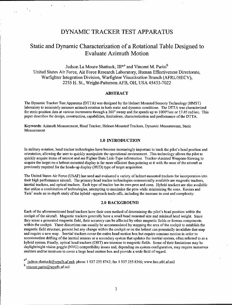
DYNAMIC TRACKER TEST APPARATUS
Static and Dynamic Characterization of a Rotational Table Designed toEvaluate Azimuth Motion
Judson La Moure Shattuck, III*a and Vincent M. Parisib
United States Air Force, Air Force Research Laboratory, Human Effectiveness Directorate,Warfighter Integration Division, Warfighter Visualization Branch (AFRL/HECV),
2255 H. St., Wright-Patterson AFB, OH, USA 45433-7022
ABSTRACT
The Dynamic Tracker Test Apparatus (DTTA) was designed by the Helmet Mounted Sensory Technology (HMST)laboratory to accurately measure azimuth rotation in both static and dynamic conditions. The DTTA was characterizedfor static position data at various increments through a 3600 sweep and for speeds up to 1000°/sec or 17.45 rad/sec. Thispaper describes the design, construction, capabilities, limitations, characterization and performance of the DTTA.
Keywords: Azimuth Measurement, Head Tracker, Helmet-Mounted Trackers, Dynamic Measurement, StaticMeasurement
1.0 INTRODUCTION
In military aviation, head tracker technologies have become increasingly important to track the pilot's head position andorientation, allowing the user to quickly manipulate the operational environment. This technology allows the pilot toquickly acquire items of interest and see Fighter Data Link-Type information. Tracker-Assisted Weapons-Slewing toacquire the target on a helmet-mounted display is far more efficient than pointing at it with the nose of the aircraft aspreviously required for the heads-up display (HUD) type of target acquisition.
The United States Air Force (USAF) has used and evaluated a variety of helmet-mounted trackers for incorporation intotheir high performance aircraft. The primary head tracker technologies commercially available are magnetic trackers,inertial trackers, and optical trackers. Each type of tracker has its own pros and cons. Hybrid trackers are also availablethat utilize a combination of technologies, attempting to maximize the pros while minimizing the cons. Kocian andTask' made an in-depth study of the hybrid -approach trade-offs, including the increase in cost and complexity.
2.0 BACKGROUND
Each of the aforementioned head trackers have their own method of determining the pilot's head position within thecockpit of the aircraft. Magnetic trackers generally have a small head mounted size and minimal head weight. Sincethey sense a generated magnetic field, their accuracy can be affected by other magnetic fields or ferrous componentswithin the cockpit. These distortions can usually be accommodated by mapping the area of the cockpit to establish themagnetic field structure, present but any change within the cockpit or on the helmet can potentially invalidate that mapand require a new map. Inertial trackers cover the entire head motion box but require constant motion in order toaccommodate drifting of the inertial sensors or a secondary system that updates the inertial system, often referred to as ahybrid system. Finally, optical head trackers (OHT) are immune to magnetic fields. Some of their limitations may bedaylight/night vision goggle (NVG) compatibility issues and, depending on system configuration, may require numerousemitters and/or receivers to cover a large head motion box and provide a wide field of regard.
a*judson.shattuck~wp afb.af.mil; phone 1 937 255 8742; fax 1 937 255 8366; www.hec.afrl.af.milb .vlncent.parisi~wwpafb.af.mil
With the variety of commercialized head trackers available to the USAF, a method to evaluate these various types isnecessary. The evaluation method must not interfere with the head trackers normal function. That is, it must not subjectthe head tracker to excessive ferrous components that would alter magnetic trackers fields for magnetic trackers, createexcessive vibration for inertial trackers, or produce excessive light for optical trackers.
Contained in this text is a description of the Dynamic Tracker Test Apparatus (DTTA), which attempts to fulfill thisrequirement.
3.0 SYSTEM DESCRIPTION
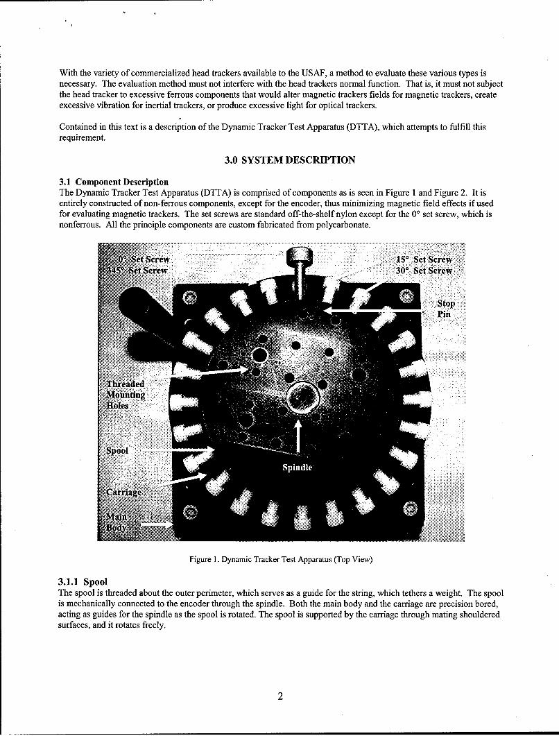
3.1 Component DescriptionThe Dynamic Tracker Test Apparatus (DTTA) is comprised of components as is seen in Figure 1 and Figure 2. It isentirely constructed of non-ferrous components, except for the encoder, thus minimizing magnetic field effects if usedfor evaluating magnetic trackers. The set screws are standard off-the-shelf nylon except for the 0' set screw, which isnonferrous. All the principle components are custom fabricated from polycarbonate.
0' St Scew 5' Set Screw
345'Set~rew 0' Set Screw
Pin
Figure 1. Dynamic Tracker Test Apparatus (Top View)
3.1.1 Spool
The spool is threaded about the outer perimeter, which serves as a guide for the string, which tethers a weight. The spoolis mechanically connected to the encoder through the spindle. Both the main body and the carriage are precision bored,acting as guides for the spindle as the spool is rotated. The spool is supported by the carriage through mating shoulderedsurfaces, and it rotates freely.
2
The top of the spool is drilled every 1" on center with ¼"-20 threads, identical to standard optical tables. This allowsmounting of standard optical hardware, facilitating custom fixtures. The spool also includes a stop pin that extends intothe carriage. The function of the stop pin is described along with the carriage.
3.1.2 CarriageThe carriage serves two primary functions. First, it mechanically supports the spool with a mating shouldered surfaceand is precision bored to help align the spindle that connects the spool to the encoder. Second, it provides a means tomove and stop the spool at any combination of 150 increments about its 3600 rotation when the set screws are spun in.Accordingly, the carriage is drilled and threaded about its outer perimeter every 15' to accommodate mating set screws.The set screws are a position aid; they are not intended as an exact reference point.
3.1.3 EncoderThe Encoder is a metrology-grade measurement device specifically designed for rotary tables with a resolution, after 4xquadrature decode and 50x interpolation, of 0.0001' (0.36 arcsec) and an accuracy of+ 1.25 arcsec. The position dataoutput from the encoder is represented by two quadrature pulse streams that can be decoded to 3,600,000 counts perrevolution. It also includes an index marker and out-of-tolerance marker. Under dynamic conditions, the encoder canaccurately output data at a maximum rate of 1000 rev/min (RPM) or 104.7 rad/sec.
The index marker generates a high output signal at the same physical location with respect to the encoder's internal shaftonce every revolution. This index can be used to identify the absolute beginning of a rotation (0 counts) or to determinean offset, by number of counts, from where an absolute beginning is desired. Thus, the exact starting and endingposition, within 0.000 10 or 1/3,600,000 counts, can be found and repeated. The out-of-tolerance marker generates a lowpulse indicating faulty encoder operation.
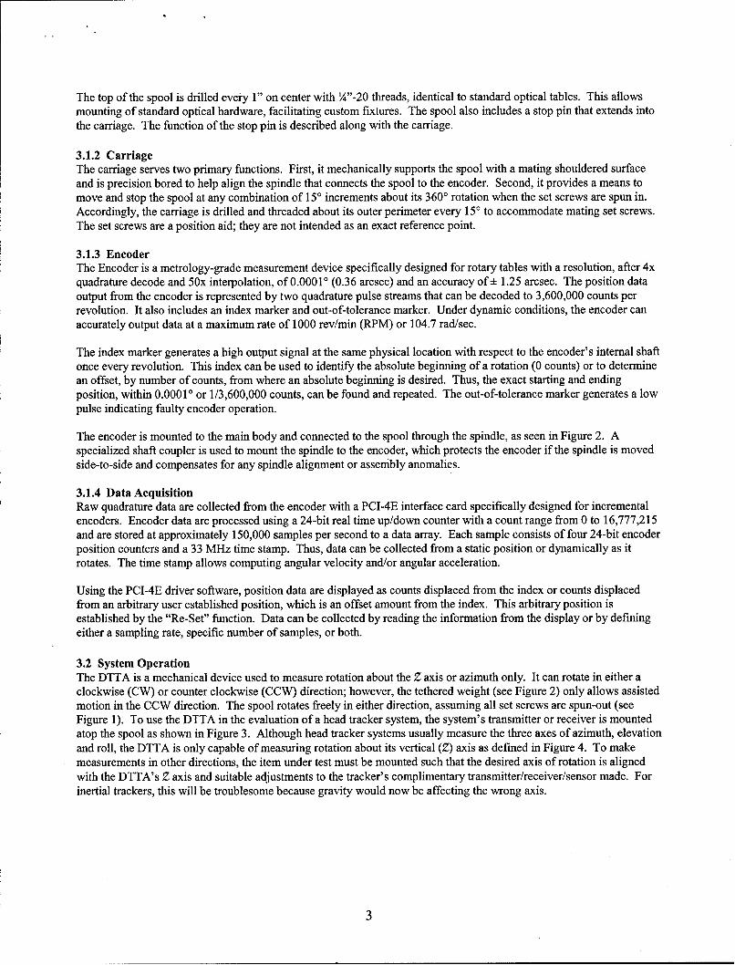
The encoder is mounted to the main body and connected to the spool through the spindle, as seen in Figure 2. Aspecialized shaft coupler is used to mount the spindle to the encoder, which protects the encoder if the spindle is movedside-to-side and compensates for any spindle alignment or assembly anomalies.
3.1.4 Data AcquisitionRaw quadrature data are collected from the encoder with a PCI-4E interface card specifically designed for incrementalencoders. Encoder data are processed using a 24-bit real time up/down counter with a count range from 0 to 16,777,215and are stored at approximately 150,000 samples per second to a data array. Each sample consists of four 24-bit encoderposition counters and a 33 MHz time stamp. Thus, data can be collected from a static position or dynamically as itrotates. The time stamp allows computing angular velocity and/or angular acceleration.
Using the PCI-4E driver software, position data are displayed as counts displaced from the index or counts displacedfrom an arbitrary user established position, which is an offset amount from the index. This arbitrary position isestablished by the "Re-Set" function. Data can be collected by reading the information from the display or by definingeither a sampling rate, specific number of samples, or both.
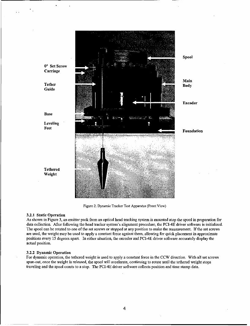
3.2 System OperationThe DTTA is a mechanical device used to measure rotation about the Z axis or azimuth only. It can rotate in either aclockwise (CW) or counter clockwise (CCW) direction; however, the tethered weight (see Figure 2) only allows assistedmotion in the CCW direction. The spool rotates freely in either direction, assuming all set screws are spun-out (seeFigure 1). To use the DTTA in the evaluation of a head tracker system, the system's transmitter or receiver is mountedatop the spool as shown in Figure 3. Although head tracker systems usually measure the three axes of azimuth, elevationand roll, the DTIA is only capable of measuring rotation about its vertical (Z) axis as defined in Figure 4. To makemeasurements in other directions, the item under test must be mounted such that the desired axis of rotation is alignedwith the DTTA's Z axis and suitable adjustments to the tracker's complimentary transmitter/receiver/sensor made. Forinertial trackers, this will be troublesome because gravity would now be affecting the wrong axis.
Spool
00 Set ScrewCarriage
MainTether 7 BodyGuide
Encoder
LevelingFeet
Foundation
TetheredWeight
Figure 2. Dynamic Tracker Test Apparatus (Front View)
3.2.1 Static OperationAs shown in Figure 3, an emitter pack from an optical head tracking system is mounted atop the spool in preparation fordata collection. After following the head tracker system's alignment procedure, the PCI-4E driver software is initialized.The spool can be rotated to one of the set screws or stopped at any position to make the measurement. If the set screwsare used, the weight may be used to apply a constant force against them, allowing for quick placement in approximatepositions every 15 degrees apart. In either situation, the encoder and PCI-4E driver software accurately display theactual position.
3.2.2 Dynamic OperationFor dynamic operation, the tethered weight is used to apply a constant force in the CCW direction. With all set screwsspun-out, once the weight is released, the spool will accelerate, continuing to rotate until the tethered weight stopstraveling and the spool coasts to a stop. The PCI-4E driver software collects position and time stamp data.
4
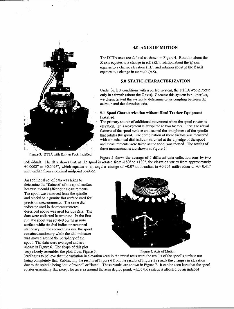
4.0 AXES OF MOTION
The DTTA axes are defined as shown in Figure 4. Rotation about theX axis equates to a change in roll (RL), rotation about the V axisequates to a change elevation (EL), and rotation about in the Z axisequates to a change in azimuth (AZ).
5.0 STATIC CHARACTERIZATION
Under perfect conditions with a perfect system, the DTTA would rotateonly in azimuth (about the Z axis). Because this system is not perfect,we characterized the system to determine cross coupling between theazimuth and the elevation axis.
5.1 Spool Characterization without Head Tracker EquipmentInstalledThe primary source of additional movement when the spool rotates iselevation. This movement is attributed to two factors. First, the actualflatness of the spool surface and second the straightness of the spindlethat rotates the spool. The combination of these factors was measuredwith a mechanical dial indictor mounted at the top edge of the spooland measurements were taken as the spool was rotated. The results ofthese measurements are shown in Figure 5.
Figure 3. DTTA with Emitter Pack Installed Figure 5 shows the average of 5 different data collection runs by twoindividuals. The data shows that, as the spool is rotated from -180' to +180', the elevation varies from approximately+0.0002" to +0.0026", which equates to an angular change of +0.07 milli-radian to +0.904 milli-radian or +/- 0.417milli-radian from a nominal midpoint position.
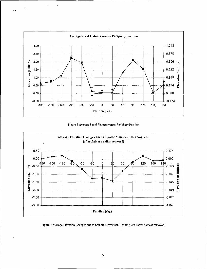
An additional set of data was taken todetermine the "flatness" of the spool surfacebecause it could affect our measurements.The spool was removed from the spindleand placed on a granite flat surface used forprecision measurements. The same dialindicator used in the measurementsdescribed above was used for this data. Thedata were collected in two runs. In the firstrun, the spool was rotated on the granitesurface while the dial indicator remainedstationary. In the second data run, the spoolremained stationary while the dial indicatorwas moved around the periphery of thespool. The data were averaged and areshown in Figure 6. The shape of this plotvery closely resembles the plots from Figure 5, Figure 4. Axis of Motionleading us to believe that the variation in elevation seen in the initial tests were the results of the spool's surface notbeing completely flat. Subtracting the results of Figure 6 from the results of Figure 5 reveals the changes in elevationdue to the spindle being "out of round" or "bent". These results are shown in Figure 7. It can be seen here that the spoolrotates essentially flat except for an area around the zero degree point, where the system is affected by an induced
5
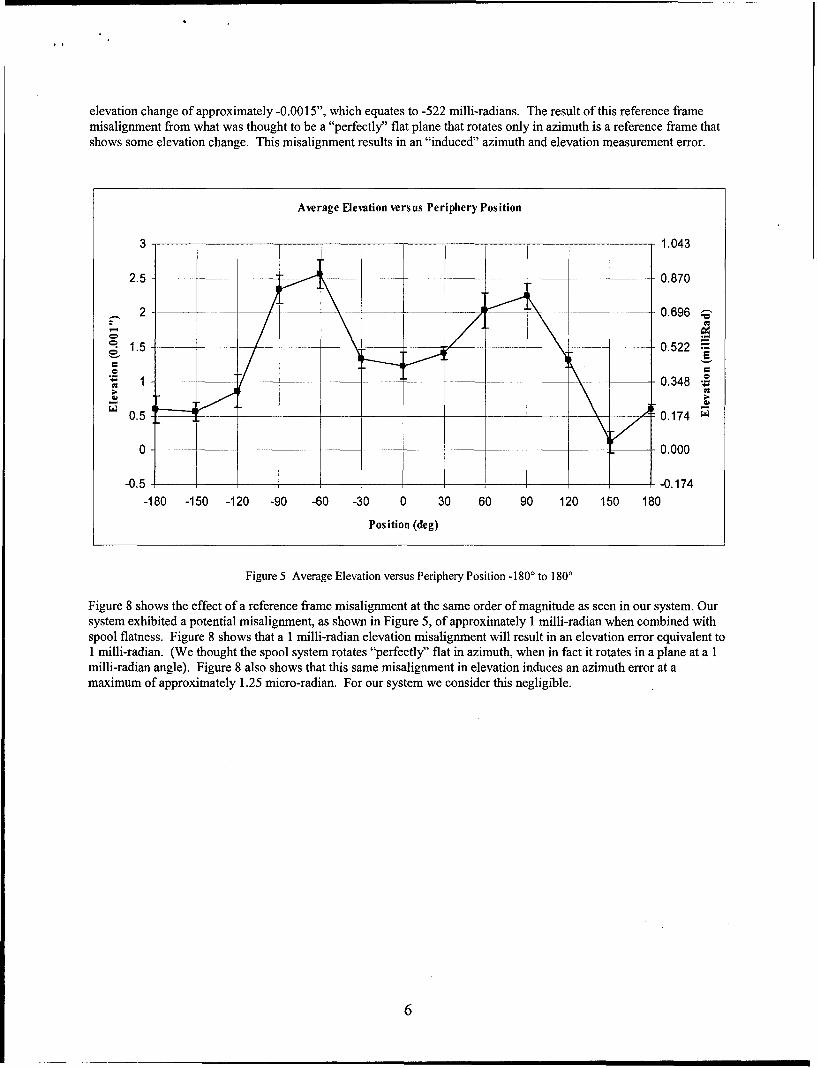
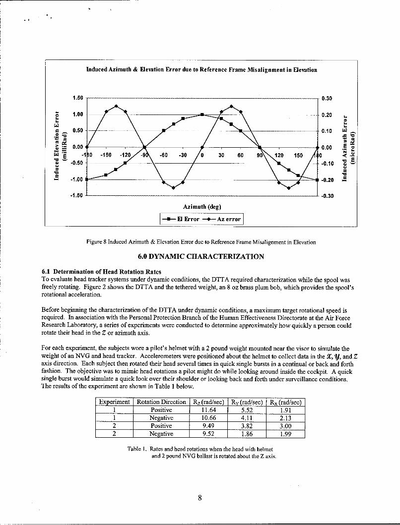
elevation change of approximately -0.0015", which equates to -522 milli-radians. The result of this reference framemisalignment from what was thought to be a "perfectly" flat plane that rotates only in azimuth is a reference frame thatshows some elevation change. This misalignment results in an "induced" azimuth and elevation measurement error.
Average Elevation versus Periphery Position
3 - 1.043
2.5 - l-. 0.870
2 __ 1__ __0.696 •'
1.j5 •_ 0.522
.o
S1 __ ____0.348 .
__0.5 _ _0.174 m
0 - - 0.000
-0.5 i -0.174-180 -150 -120 -90 -60 -30 0 30 60 90 120 150 180
Position (deg)
Figure 5 Average Elevation versus Periphery Position -180' to 1800
Figure 8 shows the effect of a reference frame misalignment at the same order of magnitude as seen in our system. Oursystem exhibited a potential misalignment, as shown in Figure 5, of approximately 1 milli-radian when combined withspool flatness. Figure 8 shows that a I milli-radian elevation misalignment will result in an elevation error equivalent to1 milli-radian. (We thought the spool system rotates "perfectly" flat in azimuth, when in fact it rotates in a plane at a 1milli-radian angle). Figure 8 also shows that this same misalignment in elevation induces an azimuth error at amaximum of approximately 1.25 micro-radian. For our system we consider this negligible.
6
Average Spool Flatness versus Periphery Position
3.00 - 1.043
2.50 0.870
2.00 _____ ____ _ ____ __ 0.696 C
1.50- -- 0.522
• 1.00 , 0.348 .2
S0.50 _ 0.174
0.00 _ _.-_0.000
-0.50 -0.174-180 -150 -120 -90 -60 -30 0 30 60 90 120 150 180
Position (deg)
Figure 6 Average Spool Flatness versus Periphery Position
Average Elevation Changes due to Spindle Movement, Bending, etc.
(after flatness deltas removed)
0.50 0.174
0.00 1__ 0.000______
= -0.0-30 -150 -120 .c E 0 - 400 30) 6 10 12.0 1 • 0 ,-,O"-0.50 - 10 - -0.174
,-
o-1.00 -0.348
-1.50 -0.522 0
• -2.00 -0.696 C-
-2.50 -0.870
-3.00 -1.043
Poistion (deg)
Figure 7 Average Elevation Changes due to Spindle Movement, Bending, etc. (after flatness removed)
Induced Azimuth & Elevation Error due to Reference Frame Misalignment in Elevation
1.50 0.30
o 1.00 0.20 LL_ o
0=• .50 0.1o0 •g
.0.50 -- - 0.10
0" -1.00 -0.20 .
-1.50 -0.30
Azimuth (deg)
E---Fl Error -4--Az error
Figure 8 Induced Azimuth & Elevation Error due to Reference Frame Misalignment in Elevation
6.0 DYNAMIC CHARACTERIZATION
6.1 Determination of Head Rotation RatesTo evaluate head tracker systems under dynamic conditions, the DTTA required characterization while the spool wasfreely rotating. Figure 2 shows the DTTA and the tethered weight, an 8 oz brass plum bob, which provides the spool'srotational acceleration.
Before beginning the characterization of the DTTA under dynamic conditions, a maximum target rotational speed isrequired. In association with the Personal Protection Branch of the Human Effectiveness Directorate at the Air ForceResearch Laboratory, a series of experiments were conducted to determine approximately how quickly a person couldrotate their head in the Z or azimuth axis.
For each experiment, the subjects wore a pilot's helmet with a 2 pound weight mounted near the visor to simulate theweight of an NVG and head tracker. Accelerometers were positioned about the helmet to collect data in the X, V, and Zaxis direction. Each subject then rotated their head several times in quick single bursts in a continual or back and forthfashion. The objective was to mimic head rotations a pilot might do while looking around inside the cockpit. A quicksingle burst would simulate a quick look over their shoulder or looking back and forth under surveillance conditions.The results of the experiment are shown in Table I below.
Experiment Rotation Direction Rz (rad/sec) Ry (rad/sec) Rx (radlsec)1 Positive 11.64 5.52 1.911 Negative 10.66 4.11 2.132 Positive 9.49 3.82 3.002 Negative 9.52 1.86 1.99
Table 1. Rates and head rotations when the head with helmetand 2 pound NVG ballast is rotatedabout the Z axis.
8
From Table 1, it is seen that the DTTA should rotate at 11.64 rad/sec or greater. Another conclusion drawn from Table 1is that, although pure rotation about the Z axis was desired, there were rotations about the X and V axis in allexperimental runs.
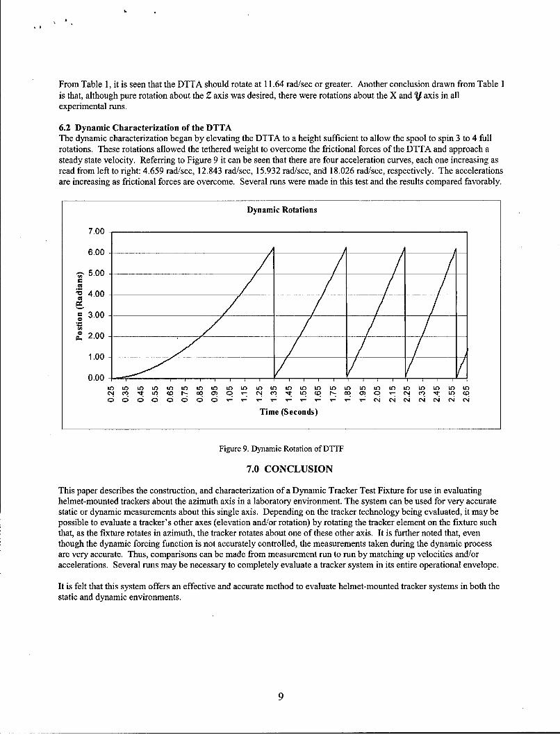
6.2 Dynamic Characterization of the DTTAThe dynamic characterization began by elevating the DTTA to a height sufficient to allow the spool to spin 3 to 4 fullrotations. These rotations allowed the tethered weight to overcome the frictional forces of the DTTA and approach asteady state velocity. Referring to Figure 9 it can be seen that there are four acceleration curves, each one increasing asread from left to right: 4.659 rad/sec, 12.843 rad/sec, 15.932 rad/sec, and 18.026 rad/sec, respectively. The accelerationsare increasing as frictional forces are overcome. Several runs were made in this test and the results compared favorably.
Dynamic Rotations
7.00
6.00 _
'. 5.00
4.00
3.00 -
, 2.00 /
1.00 _
0.000O 10 LO Lo 1O LO 1O U0 1O to 1 O U" 1 O 1 O 1 O 10 1 O 10 V0 W0 to 10 W 10 1 0
0 0 0 0 0 0 0 0 C - - - - - - - - - - C C C C C CC
Time (Seconds)
Figure 9. Dynamic Rotation of DTTF
7.0 CONCLUSION
This paper describes the construction, and characterization of a Dynamic Tracker Test Fixture for use in evaluatinghelmet-mounted trackers about the azimuth axis in a laboratory environment. The system can be used for very accuratestatic or dynamic measurements about this single axis. Depending on the tracker technology being evaluated, it may bepossible to evaluate a tracker's other axes (elevation and/or rotation) by rotating the tracker element on the fixture suchthat, as the fixture rotates in azimuth, the tracker rotates about one of these other axis. It is further noted that, eventhough the dynamic forcing function is not accurately controlled, the measurements taken during the dynamic processare very accurate. Thus, comparisons can be made from measurement run to run by matching up velocities and/oraccelerations. Several runs may be necessary to completely evaluate a tracker system in its entire operational envelope.
It is felt that this system offers an effective and accurate method to evaluate helmet-mounted tracker systems in both thestatic and dynamic environments.
8.0 REFERENCE
1. Kocian, Dean F. and Task, H. Lee, "Visually Coupled Systems Hardware and Human Interface," in WoodrowBarfield and Thomas A. Furness III (eds.), Virtual Environments and Advanced Interface Design, Oxford UniversityPress, 1995
2. J.B. Kuipers, "Characterization & Application of Quaternions for Enhanced Computer Processing Algorithms", SBIRII Final Report (U), Report No. AL/CF-SR-1994-0014, Kuipers and Associates, 3085 Baker Park Drive, SoutheastGrand Rapids MI 49508-1474
9.0 ACKNOWLEDGEMENTS
The authors express their appreciation to Mr. Mike R. Sedillo and Mr. Nathan T. Kornbau for their support in setting upthese tests and for meticulous data collection. We are also thankful for the software support from Mr. Eric Heft. Finally,we thank Mr. John A. Plaga, Mr. Brian J. Grattan, and Mr. Bob J. Flannery for responding to our request concerninghead movement data and acting as subjects.
10