Embed Size (px)
Citation preview

ATTO FastStream Embedded Storage Controller
Installation and Operation Manual
Fibre Channel to SAS/SATA ModelsSC 5550E
SC 8550E
SAS to SAS/SATA ModelSC 8250E

ATTO Technology, Inc.155 CrossPoint ParkwayAmherst, New York 14068 USA
www.attotech.com
Tel (716) 691-1999Fax (716) 691-9353
Sales support: [email protected] support: Monday -- Friday, 8am-6pm EST
[email protected] (716) 691-1999 x242
© 2011 ATTO Technology, Inc. All rights reserved. All brand or product names are trademarks of their respective holders. No part of this manual may be reproduced in any form or by any means without the express written permission of ATTO Technology, Inc.
8/2011 PRMA-0407-000
Contents
1.0 ATTO FastStream Overview ..........................................................................1Technical featuresSystem memoryExpansion slotRAID protection featuresAudio/video features
1.1 ATTO FastStream Embedded Components .....................................2Board dimensionsTemperatureHumidityAltitudeESDReal Time ClockCacheAssure (optional)Power supply requirementsDevice ConnectivityHost ConnectivityManagement portsAudible AlarmManual reset switchLED
1.2 ATTO Celerity FC42-ES Host Adapter ...............................................4Hardware specificationsAdvanced FC capabilitiesHost bus specificationsExternal connectivity
1.3 ATTO Celerity FC84-EN Host Adapter ...............................................6Technical specificationsAdvanced FC capabilitiesHost bus specificationsEnvironmental & physical specificationsExternal connectivity
1.4 ATTO ExpressSAS H6F0 Host Adapter .............................................8H6F0 technical specifications
2.0 Install the FastStream ....................................................................................9Unpacking the packing box; verifying contentsInstalling the FastStreamInstalling CacheAssure (optional)Non-Volatile (NV) Memory Card InstallationPower Module InstallationDiscovering the IP addressSetting up Internet ExplorerBeginning initial configuration
3.0 Ensure Drive Integrity ....................................................................................15Before creating RAID GroupsAfter creating RAID Groups
3.1 Drive Diagnostics ................................................................................17Preliminary stepsRead-only Drive TestDrive performance and healthIdentifying a drive attached to the FastStream
3.2 DriveAssure .........................................................................................19Guaranteed LatencyRebuild Continue on ErrorInitialization Media ScrubbingMedia ScanOn-the-Fly Media Error HandlingData Recovery ModeRebuild Recovery ModeBasic Recovery ModeExtreme Recovery Mode
4.0 Configure Storage into RAID Groups ..........................................................21Features you may chooseAuto-RebuildFault ToleranceInitializationSelecting an applicationPreliminary stepsDigital VideoAudioGeneral IT or DatabaseCreating a custom setup
5.0 Modify System Values ...................................................................................26Changing current user name, passwordCreating a read-only user name, passwordChanging system variables
6.0 Monitor Storage, Configurations ..................................................................28Health and Status Monitor pageDrive HealthDrive Health DisplayConfiguration Display pageSCSI Enclosure Services (SES)
6.1 Remote System Monitoring ................................................................30Types of errorsWarning messagesMessage severity levelsEmail notification
6.2 SCSI Enclosure Services (SES) .........................................................32Setting up SESIdentifying SES elementsMonitoring SES elementsUse the Health and Status MonitorUse the Manage menuAudible Alarm
6.3 CacheAssure ..................................................................................................36Benefits of CacheAssureCacheAssure Status
7.0 Modify Storage ...............................................................................................37Preliminary stepsRAID Group processesCreating RAID GroupsDeleting RAID GroupsAdding drives to a RAID GroupAdding mirrors to a RAID configurationChanging RAID configuration: RAID migrationModifying RAID Group mappingModifying RAID Group partitionsRebuilding RAID GroupsModifying RAID optionsImporting RAID GroupsFastStream process: adding or removing Hot SparesRemoving RAID configuration dataRAID CLI page
8.0 Manage ATTO Devices, Configurations .......................................................42Creating a unique name for your FastStreamDiscovering, managing other ATTO devicesSaving or restoring a FastStream configuration fileField Replacement Unit (FRU)
9.0 Interface Options ...........................................................................................45Using the ExpressNAV Storage ManagerUsing the serial portUsing Telnet
10.0 Firmware Support ........................................................................................47Update FirmwareDual Firmware Image SupportSelectable Dual Boot Images
Appendix A Design RAID Groups ......................................................................iJBOD: Just a Bunch of DisksDVRAID: Digital Video RAIDRAID Level 0: striping, no redundancyRAID Level 1: mirroring (duplicate drives)RAID Level 1 plus additional mirroringRAID Level 1+0: striping, mirror spans two drivesRAID Level 4: striping, one parity driveRAID Level 5: striping, parity distributed among drivesRAID Level 6: striping, two parity blocks distributed among drives
Appendix B Multipathing .....................................................................................vImproved Availability of Storage with improved performanceLoad Balancing algorithms provided by ATTO MultiPath Director for OS X and a DSM MPIO
Driver for Windows ServerSetup of the FastStream with Multipathing
Appendix C Tape Pass-Through ........................................................................vi
Appendix D CLI Provides an ASCII-based Interface .........................................viiCLI error messagesCLI summaryCLI command explanations
Appendix E FibreBridge LEDs ............................................................................xxvii
Appendix F Reference Charts ..............................................................................xxviiiGenerated frequenciesData rate in cablesConnector pinoutsATX 24-pin power connector pinouts (J1)RJ-11 connection pinouts (J3)Internal SAS 4i connector pinouts (J9)RJ-45 connector pinouts (J2)Internal SAS 4i connector pinouts (J10)CacheAssure Power Pack ConnectorRS232 Header (2 x 3)Jumpers pinouts Momentary push-button header pinouts (P1)ATX power switch override header (P3)
Appendix G Standards and Compliances ..........................................................xxxiiFCC Standards: Radio and Television InterferenceCanadian StandardsEuropean StandardsDeclaration of Conformity
Appendix H Warranty ..........................................................................................xxxiii
1
1.0 ATTO FastStream OverviewThe ATTO FastStream SC 5550E, 8250E and 8550E provide class leading performance and RAID protection in an embeddable ATX form factor.
With the latest in storage connectivity technology, the ATTO FastStream provides unprecedented flexibility while adding RAID protection without compromising performance.
ATTO FastStream Embeddable Storage Controllers are high performance RAID storage devices which can be seamlessly integrated into an ATX enclosure.
ATTO FastStream FC to SAS RAID controllers are ideally suited for bandwidth intensive applications such as digital film, video and audio as well as medical imaging, digital prepress and disk to disk backup.
While RAID improves data accessibility and reliability during normal operations, you still need a good backup strategy for long-term protection of your data.
Technical features• MicroATX form factor: conforms to industry-
standard MicroATX form factor specification for board size, board mounting locations and expansion slot placement.
• Intel 81348 processor
• 2 (x4) independent SAS/SATA device connectors
• Optional external (x4) miniSAS SFF-8088 connector for JBOD expansion
• Internal wide-SAS Small Form Factor (SFF) 8087 connectors
• Dual Firmware image support
• Selectable boot images
• FastStream embeddable RAID controllers support up to 32 disk drives in an enclosure
• RS-232 management port with a back panel accessible RJ11 interface
• 10/100/1000 Megabits per second (Mb/sec.) Ethernet management port with an RJ45 connector and integrated LEDs
• 16 MB Flash
• LED status for link and speed
• Manual reset switch to reboot the Storage Controller
• Battery-backed event log asynchronous SRAM
• System monitoring hardware
• Real time clock
• SCSI Enclosure Services (SES)
System memory• One 240-pin DDR2 SDRAM DIMM connector
• Supports 1GB of unbuffered, ECC DDR2-533 SDRAM DIMM
Expansion slot• One PCIe expansion slot, x8 electrical and
mechanical widths aligned with expansion slot 7 of the standard ATX form factor
• Conforms to the PCIe Base 1.0a and CEM specifications
• Accepts an ATTO PCIe Host Adapter as the host port interface
• Host adapter is oriented perpendicular to the FastStream SC board and can be mounted parallel with an optional 90º angle adapter SKU: BRAC-PCIE-E00
RAID protection features• Hardware DVRAID, RAID Level 0, 1, 4, 5, 6,1+0
and JBOD, all user configurable
• N-way mirroring
• Global and Dedicated Hot Spares to ensure continuous operation if a drive fails. The Hot Spare automatically comes on-line and rebuild starts if a disk failure is detected
• Automatic rebuild of RAID groups and changeable Rebuild Priority keep the system operational if a drive fails
• Support for large LBAs (64-bit operating systems), partitions, partial data transfer to improve performance and minimizes memory use, and spanning
Audio/video features• DVRAID provides performance for up to 30
streams of DVCPro HD, Pro Res HQ video or 6 streams of 10-bit uncompressed HD video.
• Support for video on demand
• Support for multiple streams of audio
1.1 ATTO FastStream Embedded ComponentsThe ATTO FastStream Fibre Channel to SAS/SATA RAID controller line can be seamlessly integrated into an ATX or custom storage enclosure.
ATTO FastStream SC RAID controllers support next-generation media and are equipped to handle the throughputs needed by advanced disk technologies.
For installation instructions, refer to Install the FastStream on page 9.
Board dimensionsThe FastStream SC embedded storage controllers feature MicroATX-size printed circuit boards (PCB). The boards can be used in enclosures that have adequate clearance for the DIMM socket and allowance for connecting to internal connectors.
Width: 7.0 in. ± 0.005 in. (17.78 cm ±0.01 cm)
Length: 9.6 in. ± 0.005 in. (24.38 cm ±0.01 cm)
Height: 1.3 in. ± 0.005 in. (3.3 cm ±0.01 cm)
TemperatureNon-operating: -40 ºC to +70 ºC (-40 to 158 ºF)
Operating: +5 ºC to +40 ºC (41-113 ºF)
HumidityNon-operating: 5% to 95% non-condensing
Operating: 10% to 90% non-condensing
AltitudeNon-operating: 50,000 feet (15,240 meters)
Operating: 10,000 feet (3048 meters)
ESDContact discharge: Up to ±8kV no errors
Air discharge: Up to ±15kV no errors
Real Time ClockThe Real Time Clock uses an M41T0 from ST Microelectronics. The contents are maintained regardless of power cycles. A rechargeable 3V Lithium ion battery provides up to 90 days of backup power. The charger is integrated on the circuit board. The Lithium ion battery may explode if mistreated.
WARNINGWARNING
To prevent shorting, premature failure or damage to the battery, do not place the board on a conductive surface such as metal, black conductive foam or the outside surface of a metallized ESD protective pouch with your local environmental regulations.
CacheAssure (optional)CacheAssure™ provides confidence that your cached data will remain intact in the event of an unexpected power loss, while offering an environmentally friendly, maintenance-free solution.
Power supply requirementsA stable power source is necessary for proper and reliable operation. The FastStream requires an ATX power supply with a 24-pin ATX connector. See ATX 24-pin power connector pinouts (J1) on page xxviii of Appendix F.
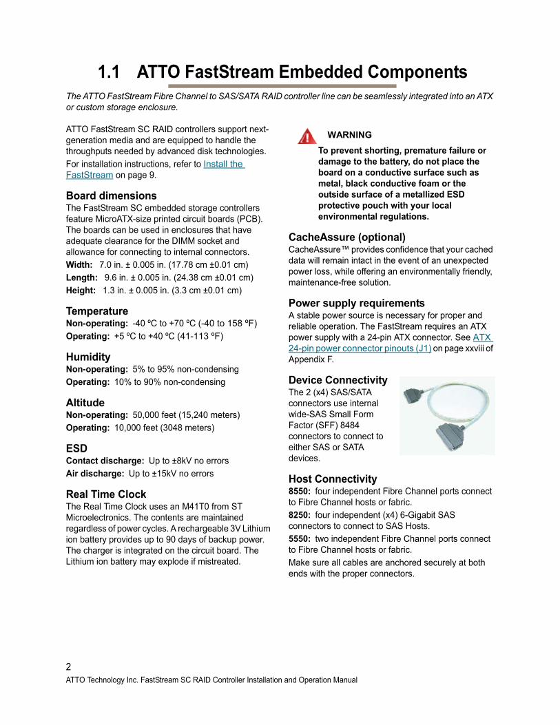
Device ConnectivityThe 2 (x4) SAS/SATA connectors use internal wide-SAS Small Form Factor (SFF) 8484 connectors to connect to either SAS or SATA devices.
Host Connectivity8550: four independent Fibre Channel ports connect to Fibre Channel hosts or fabric.
8250: four independent (x4) 6-Gigabit SAS connectors to connect to SAS Hosts.
5550: two independent Fibre Channel ports connect to Fibre Channel hosts or fabric.
Make sure all cables are anchored securely at both ends with the proper connectors.
2ATTO Technology Inc. FastStream SC RAID Controller Installation and Operation Manual
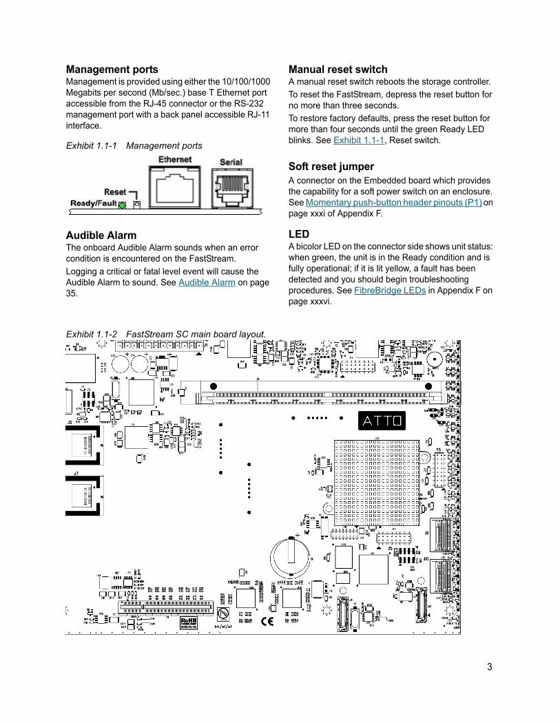
Management portsManagement is provided using either the 10/100/1000 Megabits per second (Mb/sec.) base T Ethernet port accessible from the RJ-45 connector or the RS-232 management port with a back panel accessible RJ-11 interface.
Exhibit 1.1-1 Management ports
Audible AlarmThe onboard Audible Alarm sounds when an error condition is encountered on the FastStream.
Logging a critical or fatal level event will cause the Audible Alarm to sound. See Audible Alarm on page 35.
Manual reset switchA manual reset switch reboots the storage controller.
To reset the FastStream, depress the reset button for no more than three seconds.
To restore factory defaults, press the reset button for more than four seconds until the green Ready LED blinks. See Exhibit 1.1-1, Reset switch.
Soft reset jumperA connector on the Embedded board which provides the capability for a soft power switch on an enclosure. See Momentary push-button header pinouts (P1) on page xxxi of Appendix F.
LEDA bicolor LED on the connector side shows unit status: when green, the unit is in the Ready condition and is fully operational; if it is lit yellow, a fault has been detected and you should begin troubleshooting procedures. See FibreBridge LEDs in Appendix F on page xxxvi.
Exhibit 1.1-2 FastStream SC main board layout.
3

1.2 ATTO Celerity FC42-ES Host AdapterThe ATTO FastStream SC 5550E uses the Celerity FC-42ES PCI Express Interconnect and 4-Gigabit Fibre Channel to provide performance of up to 700 MB/sec.
The Celerity FC-42ES is a dual-channel host adapter that supports high-definition video, rich content databases and other high bandwidth environments.
The FC-42ES uses PCI Express, a serial, high-speed connection that supports aggregate throughput up to 4 GB/sec. (x8 PCIe) full-duplex.
Hardware specifications• 2 independent Fibre Channel ports
• 4-Gigabit data transfer rates per channel
• Supports all FC topologies: direct fabric, arbitrated loop and point-to-point
• ANSI Fibre Channel: FC-PH, FC-AL, FC-AL2, FC-FCP, FC-PLDA, FC-FLA
• Flash ROM for easy field upgrades
• FC Class 3 support
• Local management and diagnostics
• Buffer credits: 8 @ 512 Bytes; 8 @ 2 Kilobytes
Advanced FC capabilities• Supports SNIA HBA API
• On-demand automatic negotiation among 4-Gb, 2-Gb and 1-Gb Fibre Channel
• Supports Windows FDMI and WMI
• Supports exclusive ATTO Advanced Data Streaming (ADS) Technology
Host bus specifications• x4 mechanical and x4 electrical PCI Express
interconnect (RoHS compliant)
• Conforms to PCI Express Base Spec 1.0a
• Conforms to PCI Express CEM Spec 1.0a
• PCI Express to PCI/PCI-X Bridge spec 1.0
External connectivity• Easy-to-install full height connection plate
• External LEDs for on-line and speed status for each channel
• 2 pluggable optical LC SFP transceivers included
Exhibit 1.2-1 Celerity FC-42ES Adapter bracket detail.
4ATTO Technology Inc. FastStream SC RAID Controller Installation and Operation Manual
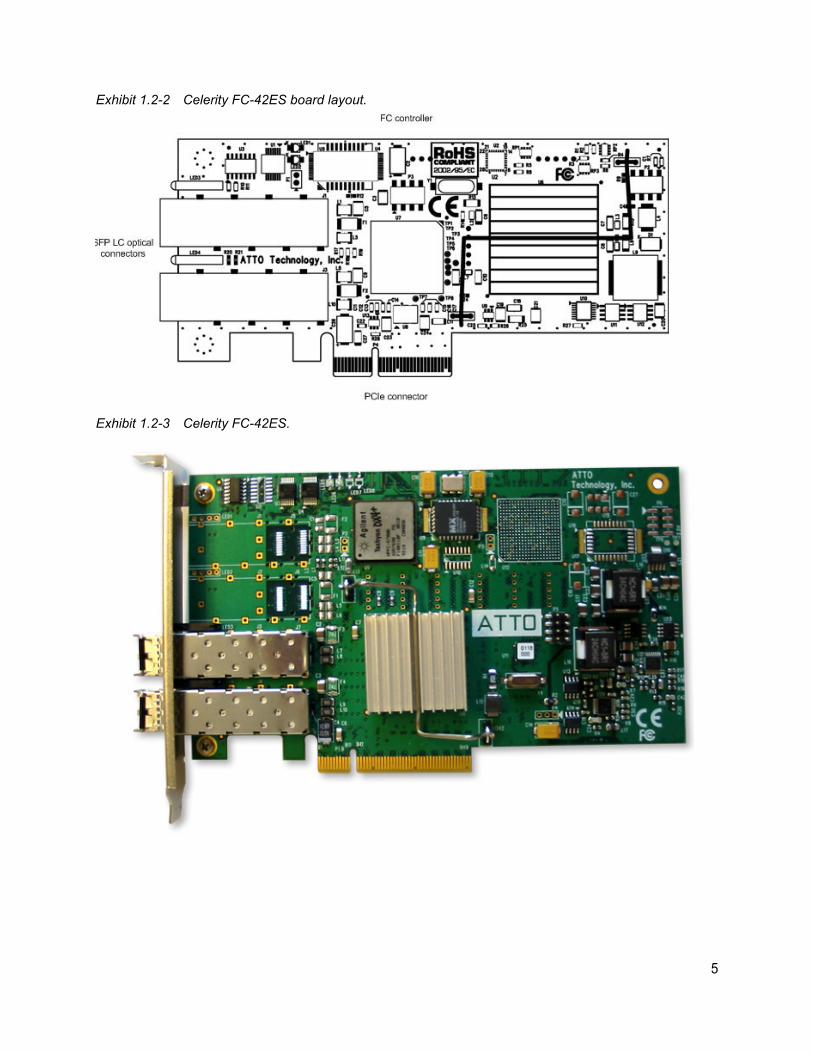
Exhibit 1.2-2 Celerity FC-42ES board layout.
Exhibit 1.2-3 Celerity FC-42ES.
5

1.3 ATTO Celerity FC84-EN Host AdapterThe ATTO FastStream SC 8550E uses the Celerity FC-84EN PCI Express Interconnect and 8-Gigabit Fibre Channel to provide performance of up to 1500 MB/sec.
The ATTO Celerity FC-84EN leverages two next-generation storage technologies: PCIe 2.0 interconnect and 8-Gigabit Fibre Channel.
The Celerity FC-84EN supports the most demanding application requirements, including high-definition video, rich content databases and other high-bandwidth environments.
ATTO Celerity host adapters are an integrated family of advanced storage connectivity solutions that are designed to provide reliable connectivity, intelligence and scalability.
Technical specifications• 4 independent Fibre Channel ports
• 8-Gigabit data transfer rates
• 1600 MB/sec. maximum full-duplex throughput per channel
• Supports all FC topologies: direct fabric, arbitrated loop and point-to-point
• ANSI Fibre Channel: FC-FS, FC-AL, FCP, FC-AL2, FC-PLDA, FC-FLA
• Flash ROM for easy field upgrades
• FC Class 3 support
• Local management and diagnostics
• Buffer credits: 41
• ATTO Advanced Data Streaming (ADS™) Technology
Advanced FC capabilities• Supports SNIA HBA API
• Backward compatible with 4-Gb and 2-Gb Fibre Channel
• Supports Windows® FDMI and WMI
Host bus specifications• x8 mechanical and x8 electrical PCI Express
interconnect
• Conforms to PCI Express Base Spec 2.0
• Conforms to PCI Express CEM Spec 2.0
• PCI Hot Plug spec 1.0
Environmental & physical specifications• Length: 6.6 inches
• Height: 3.987 inches
• Operating temperature: 0-40 ºC (32-113 ºF)
• Storage temperature: -40 to 70 ºC (-40 to 158 ºF)
• Relative humidity: 10 to 90% non-condensing
• 7.8 W (typical)
• 100 lf/m (minimum) airflow recommended
• RoHS compliant
External connectivity• Easy to install full height connection bracket
• External LEDs for on-line and speed status for each channel
• Four pluggable 8-Gb optical LC SFP+ modules included
Exhibit 1.3-1 Celerity FC-84EN.
6ATTO Technology Inc. FastStream SC RAID Controller Installation and Operation Manual
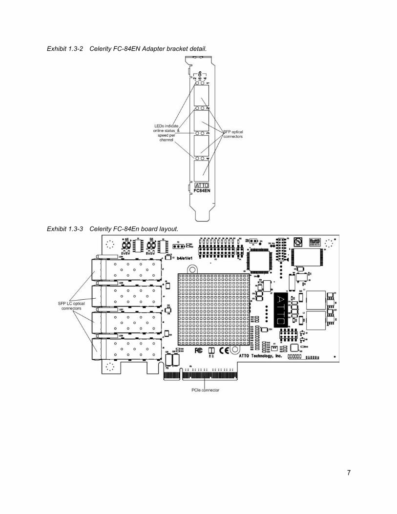
Exhibit 1.3-2 Celerity FC-84EN Adapter bracket detail.
Exhibit 1.3-3 Celerity FC-84En board layout.
7
8ATTO Technology Inc. FastStream SC RAID Controller Installation and Operation Manual
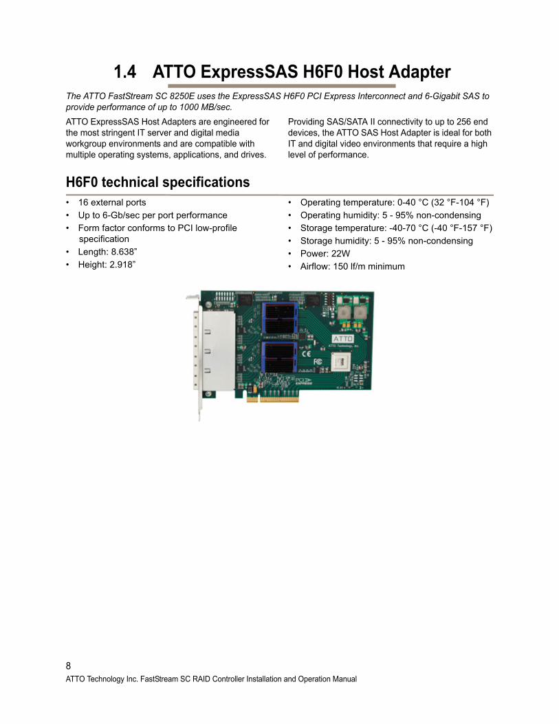
1.4 ATTO ExpressSAS H6F0 Host AdapterThe ATTO FastStream SC 8250E uses the ExpressSAS H6F0 PCI Express Interconnect and 6-Gigabit SAS to provide performance of up to 1000 MB/sec.
ATTO ExpressSAS Host Adapters are engineered for the most stringent IT server and digital media workgroup environments and are compatible with multiple operating systems, applications, and drives.
Providing SAS/SATA II connectivity to up to 256 end devices, the ATTO SAS Host Adapter is ideal for both IT and digital video environments that require a high level of performance.
H6F0 technical specifications• 16 external ports
• Up to 6-Gb/sec per port performance
• Form factor conforms to PCI low-profile specification
• Length: 8.638”
• Height: 2.918”
• Operating temperature: 0-40 °C (32 °F-104 °F)
• Operating humidity: 5 - 95% non-condensing
• Storage temperature: -40-70 °C (-40 °F-157 °F)
• Storage humidity: 5 - 95% non-condensing
• Power: 22W
• Airflow: 150 lf/m minimum
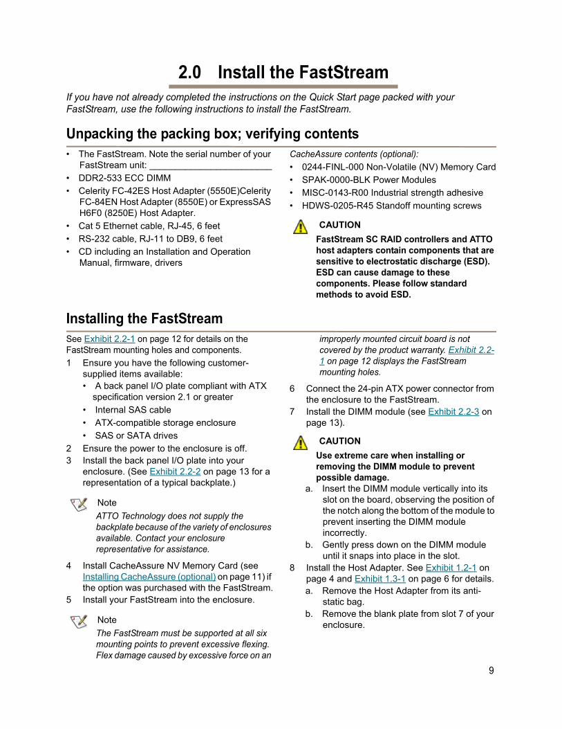
2.0 Install the FastStreamIf you have not already completed the instructions on the Quick Start page packed with your FastStream, use the following instructions to install the FastStream.
Unpacking the packing box; verifying contents• The FastStream. Note the serial number of your
FastStream unit: ________________________
• DDR2-533 ECC DIMM
• Celerity FC-42ES Host Adapter (5550E)Celerity FC-84EN Host Adapter (8550E) or ExpressSAS H6F0 (8250E) Host Adapter.
• Cat 5 Ethernet cable, RJ-45, 6 feet
• RS-232 cable, RJ-11 to DB9, 6 feet
• CD including an Installation and Operation Manual, firmware, drivers
CacheAssure contents (optional):
• 0244-FINL-000 Non-Volatile (NV) Memory Card
• SPAK-0000-BLK Power Modules
• MISC-0143-R00 Industrial strength adhesive
• HDWS-0205-R45 Standoff mounting screws
CAUTIONCAUTION
FastStream SC RAID controllers and ATTO host adapters contain components that are sensitive to electrostatic discharge (ESD). ESD can cause damage to these components. Please follow standard methods to avoid ESD.
Installing the FastStreamSee Exhibit 2.2-1 on page 12 for details on the FastStream mounting holes and components.
1 Ensure you have the following customer-supplied items available:• A back panel I/O plate compliant with ATX
specification version 2.1 or greater
• Internal SAS cable
• ATX-compatible storage enclosure
• SAS or SATA drives
2 Ensure the power to the enclosure is off.3 Install the back panel I/O plate into your
enclosure. (See Exhibit 2.2-2 on page 13 for a representation of a typical backplate.)
Note
ATTO Technology does not supply the backplate because of the variety of enclosures available. Contact your enclosure representative for assistance.
4 Install CacheAssure NV Memory Card (see Installing CacheAssure (optional) on page 11) if the option was purchased with the FastStream.
5 Install your FastStream into the enclosure.
Note
The FastStream must be supported at all six mounting points to prevent excessive flexing. Flex damage caused by excessive force on an
improperly mounted circuit board is not covered by the product warranty. Exhibit 2.2-1 on page 12 displays the FastStream mounting holes.
6 Connect the 24-pin ATX power connector from the enclosure to the FastStream.
7 Install the DIMM module (see Exhibit 2.2-3 on page 13).
CAUTIONCAUTION
Use extreme care when installing or removing the DIMM module to prevent possible damage.
a. Insert the DIMM module vertically into its slot on the board, observing the position of the notch along the bottom of the module to prevent inserting the DIMM module incorrectly.
b. Gently press down on the DIMM module until it snaps into place in the slot.
8 Install the Host Adapter. See Exhibit 1.2-1 on page 4 and Exhibit 1.3-1 on page 6 for details.
a. Remove the Host Adapter from its anti-static bag.
b. Remove the blank plate from slot 7 of your enclosure.
9
c. Position the host adapter directly above the PCIe slot and push the card straight down. For easier installation, place one end of the host adapter into the slot first, then gently push on each end until the unit is seated.
d. To ensure the card is seated completely, give it an extra uniform push on each end simultaneously.
e. Install the panel screw to secure the card.9 Attach FastStream internal SAS I/O cables. The internal SAS physical interface consists of
the 32-pin SFF-8087 connectors. The internal cable can be unshielded and should terminate from the SFF-8087 connector in the enclosure.
a. Plug in the corresponding end of the internal SAS cable to the FastStream SC internal SAS connector (port A and/or port B).
b. Plug in the opposite end of the internal SAS connector to the corresponding connector of the enclosure backplane or SAS/SATA peripheral.
10 Attach a management interface cable. You may manage the FastStream using either
an RJ-45 Ethernet cable or an RJ-11 serial cable.The preferred management tool is the ExpressNAV graphical user interface accessed through the Ethernet cable.
RJ-45 Ethernet cable: A board-mounted RJ-45 connector at the back I/O panel connects with a 10/100/1000 baseT category 5 or 6 Ethernet cable. If using an Ethernet network at 1000 baseT, use a category 6 cable to make the connection. The FastStream ships with Cat 5 cable.
a. Align the tab on the Ethernet cable with the tab on the Ethernet port of the FastStream.
b. Insert the cable until it positively mates and locks into place.
RJ-11 serial cable: A board-mounted RJ-11 cable at the back I/O panel makes connection with an RS-232 serial port for appliance management.
a. Align the tab on the provided serial cable with the tab on the RJ-11 serial port of the FastStream
b. Insert the cable until it positively mates and locks into place.
c. Insert the other end of the serial cable into the DB9 port of the PC being used for appliance control.
11 Install drives into your enclosure according to the enclosure and drive manufacturers’ instructions.
12 Put the cover back on the enclosure.13 Power up the unit.
10ATTO Technology Inc. FastStream SC RAID Controller Installation and Operation Manual
Installing CacheAssure (optional)If you have opted for a FastStream without the CacheAssure option, please advance to Exhibit 2.2-1 on page 12 and continue on.
WARNING
ATTO CacheAssure modules contain components that are sensitive to electrostatic discharge (ESD). ESD can cause damage to the FastStream RAID Controller. Please follow standard methods to avoid ESD.
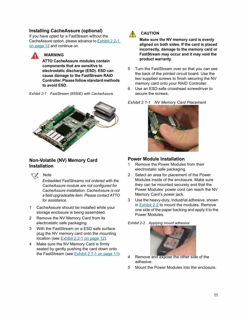
Exhibit 2-1 FastStream (8550E) with CacheAssure
Non-Volatile (NV) Memory Card Installation
Note
Embedded FastStreams not ordered with the CacheAssure module are not configured for CacheAssure installation. CacheAssure is not a field upgradeable item. Please contact ATTO for assistance.
1 CacheAssure should be installed while your storage enclosure is being assembled.
2 Remove the NV Memory Card from its electrostatic safe packaging.
3 With the FastStream on a ESD safe surface plug the NV memory card onto the mounting location (see Exhibit 2.2-1 on page 12).
4 Make sure the NV Memory Card is firmly seated by gently pushing the card down onto the FastStream (see Exhibit 2.1-1 on page 11).
CAUTIONCAUTION
Make sure the NV memory card is evenly aligned on both sides. If the card is placed incorrectly, damage to the memory card or FastStream may occur and it may void the product warranty.
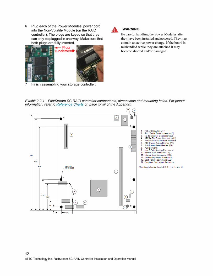
5 Turn the FastStream over so that you can see the back of the printed circuit board. Use the two supplied screws to finish securing the NV memory card onto your RAID Controller.
6 Use an ESD-safe crosshead screwdriver to secure the screws.
Exhibit 2.1-1 NV Memory Card Placement
Power Module Installation1 Remove the Power Modules from their
electrostatic safe packaging.
2 Select an area for placement of the Power Modules inside of the enclosure. Make sure they can be mounted securely and that the Power Modules’ power cord can reach the NV Memory Card’s power jack.
3 Use the heavy-duty, industrial adhesive, shown in Exhibit 2-2 to mount the modules. Remove one side of the paper backing and apply it to the Power Modules.
Exhibit 2-2 Applying mount adhesive
4 Remove and expose the other side of the adhesive.
5 Mount the Power Modules into the enclosure.
11
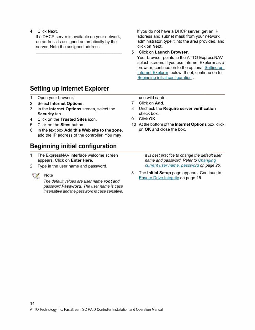
6 Plug each of the Power Modules’ power cord into the Non-Volatile Module (on the RAID controller). The plugs are keyed so that they can only be plugged in one way. Make sure that both plugs are fully inserted.
7 Finish assembling your storage controller.
WARNING
Be careful handling the Power Modules after they have been installed and powered. They may contain an active power charge. If the board is mishandled while they are attached it may become shorted and/or damaged.
Exhibit 2.2-1 FastStream SC RAID controller components, dimensions and mounting holes. For pinout information, refer to Reference Charts on page xxviii of the Appendix.
12ATTO Technology Inc. FastStream SC RAID Controller Installation and Operation Manual
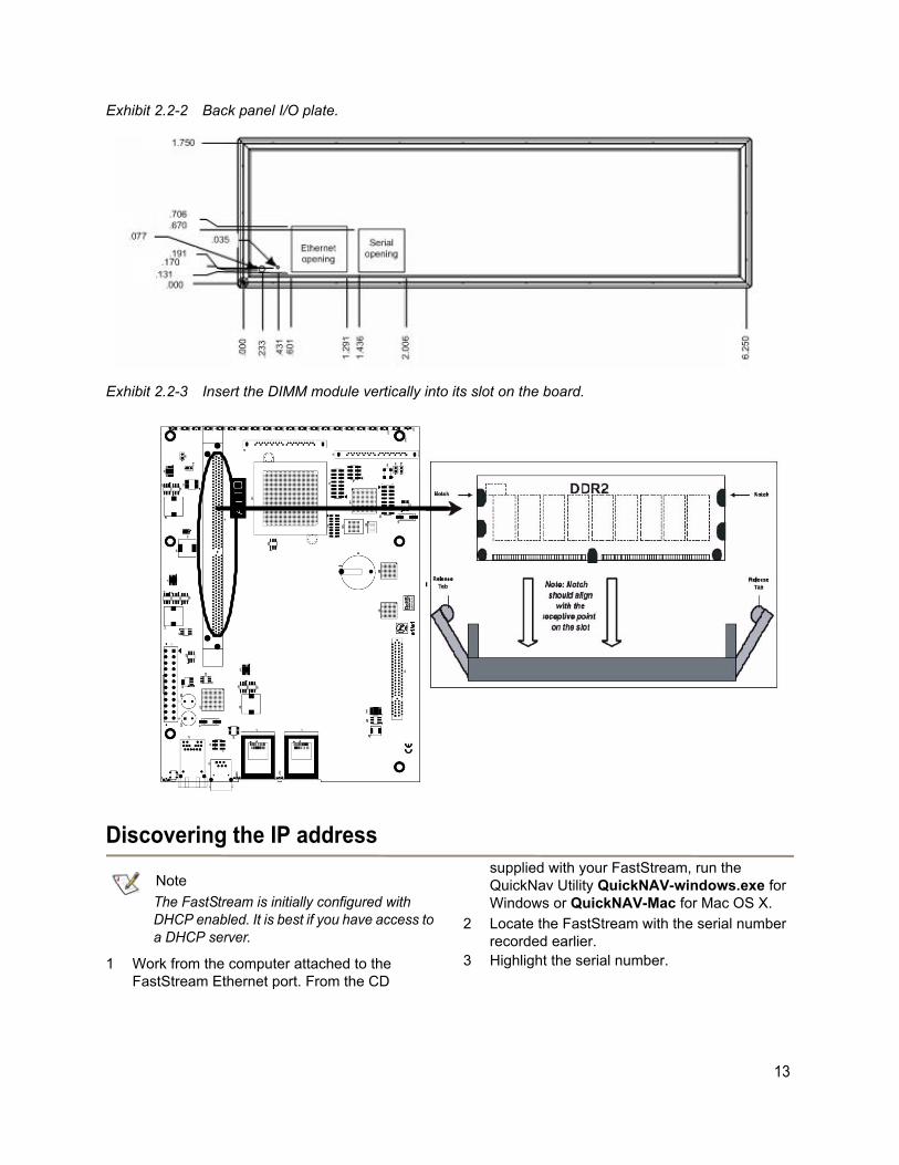
Exhibit 2.2-2 Back panel I/O plate.
Exhibit 2.2-3 Insert the DIMM module vertically into its slot on the board.
Discovering the IP address
Note
The FastStream is initially configured with DHCP enabled. It is best if you have access to a DHCP server.
1 Work from the computer attached to the FastStream Ethernet port. From the CD
supplied with your FastStream, run the QuickNav Utility QuickNAV-windows.exe for Windows or QuickNAV-Mac for Mac OS X.
2 Locate the FastStream with the serial number recorded earlier.
3 Highlight the serial number.
13
4 Click Next. If a DHCP server is available on your network,
an address is assigned automatically by the server. Note the assigned address: _____________________________________
If you do not have a DHCP server, get an IP address and subnet mask from your network administrator, type it into the area provided, and click on Next.
5 Click on Launch Browser. Your browser points to the ATTO ExpressNAV
splash screen. If you use Internet Explorer as a browser, continue on to the optional Setting up Internet Explorer below. If not, continue on to Beginning initial configuration .
Setting up Internet Explorer 1 Open your browser.
2 Select Internet Options.3 In the Internet Options screen, select the
Security tab.4 Click on the Trusted Sites icon.5 Click on the Sites button.6 In the text box Add this Web site to the zone,
add the IP address of the controller. You may
use wild cards.7 Click on Add.8 Uncheck the Require server verification
check box.9 Click OK.10 At the bottom of the Internet Options box, click
on OK and close the box.
Beginning initial configuration1 The ExpressNAV interface welcome screen
appears. Click on Enter Here.
2 Type in the user name and password.
Note
The default values are user name root and password Password. The user name is case insensitive and the password is case sensitive.
It is best practice to change the default user name and password. Refer to Changing current user name, password on page 26.
3 The Initial Setup page appears. Continue to Ensure Drive Integrity on page 15.
14ATTO Technology Inc. FastStream SC RAID Controller Installation and Operation Manual
3.0 Ensure Drive IntegrityA key component to ATTO’s DriveAssure™ technology is the ATTO FastStream’s “Initialize and Verify drive” feature which discovers and remaps bad sectors on drives, providing reliable media for your RAID Groups.
Before creating any RAID Group you should Initialize and Verify the drives you want in the RAID Group to ensure drive integrity. When selected, the FastStream writes a pattern to the entire drive, verifying the drive’s readiness and reliability.
CAUTIONCAUTION
Selecting Drive Initialization causes all previous storage data on the drive to be erased. Make sure all of your information is backed up before initializing drives.
During initialization and verification, the FastStream collects performance measurements. Performance data is available once initialization begins. You may view it from the Drive Performance and Health page accessible from the Diagnostics menu. This performance data is lost when the controller is powered off.
If you do not want to initialize or verify drives now, continue on to Configure Storage into RAID Groups on page 21.
Check drive integrity after you have created RAID Groups on drives which you wish to add to your FastStream configuration. This can be accomplished by using the Initialize and Verify procedure or a read-only scan of drives.
The Read-Only Drive Test performs a non-destructive scan over the entire surface of each drive to identify bad areas of disk drives and determine read performance. It may be run while data is passing through the FastStream.
Running this test may negatively impact performance. Once the Read-Only Drive Test has completed, system operation returns to normal.
Before creating RAID Groups1 If you are not already in the ExpressNAV
Storage Manager, type the IP address of your controller in a standard browser. On the splash screen, click Enter Here. In the box provided, type in your user name and password, and click OK.
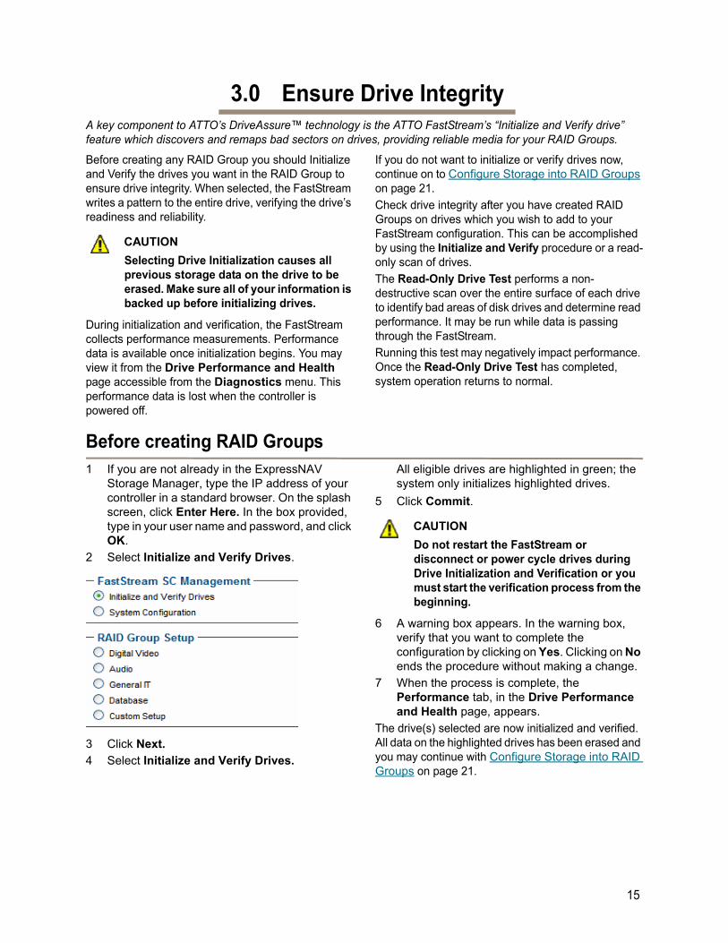
2 Select Initialize and Verify Drives.
3 Click Next.
4 Select Initialize and Verify Drives.
All eligible drives are highlighted in green; the system only initializes highlighted drives.
5 Click Commit.
CAUTIONCAUTION
Do not restart the FastStream or disconnect or power cycle drives during Drive Initialization and Verification or you must start the verification process from the beginning.
6 A warning box appears. In the warning box, verify that you want to complete the configuration by clicking on Yes. Clicking on No ends the procedure without making a change.
7 When the process is complete, the Performance tab, in the Drive Performance and Health page, appears.
The drive(s) selected are now initialized and verified. All data on the highlighted drives has been erased and you may continue with Configure Storage into RAID Groups on page 21.
15
After creating RAID Groups1 If you are not already in the
ExpressNAV Storage Manager, type the IP address of your controller in a standard browser. On the splash screen, click Enter Here. In the box provided, type in your user name and password, and click OK.
2 Click on the Diagnostics button on the left hand side of the ExpressNAV Storage Manager.
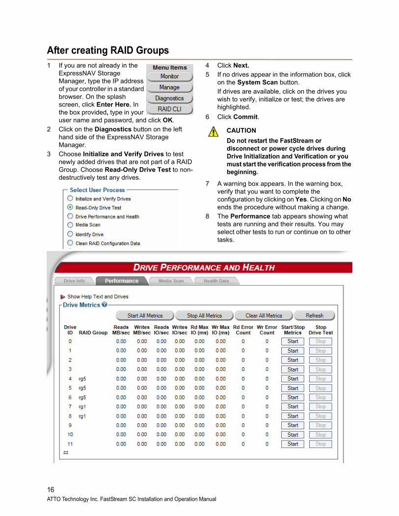
3 Choose Initialize and Verify Drives to test newly added drives that are not part of a RAID Group. Choose Read-Only Drive Test to non-destructively test any drives.
4 Click Next.
5 If no drives appear in the information box, click on the System Scan button.
If drives are available, click on the drives you wish to verify, initialize or test; the drives are highlighted.
6 Click Commit.
CAUTIONCAUTION
Do not restart the FastStream or disconnect or power cycle drives during Drive Initialization and Verification or you must start the verification process from the beginning.
7 A warning box appears. In the warning box, verify that you want to complete the configuration by clicking on Yes. Clicking on No ends the procedure without making a change.
8 The Performance tab appears showing what tests are running and their results. You may select other tests to run or continue on to other tasks.
16ATTO Technology Inc. FastStream SC Installation and Operation Manual
3.1 Drive DiagnosticsYou may determine the performance of drives attached to the FastStream using various displays and tests in ExpressNAV Storage Manager.
The following instructions assume you have already set up at least one RAID Group.
The ATTO FastStream collects various metrics to measure performance for physical drives attached to the FastStream during normal system operation and drive initialization and verification.
New performance data is updated every 60 seconds which impacts performance slightly, even if you minimize the browser window. Exit the ExpressNAV Storage Manager completely whenever you need maximum performance.
Note
Initialize and Verify Drives is Described in Section 3.0, Ensure Drive Integrity on page 15.
Preliminary steps1 If you are not already in the ExpressNAV
Storage Manager, type the IP address of your controller in a standard browser. On the splash screen, click Enter Here. In the box provided, type in your user name and password, and click OK.
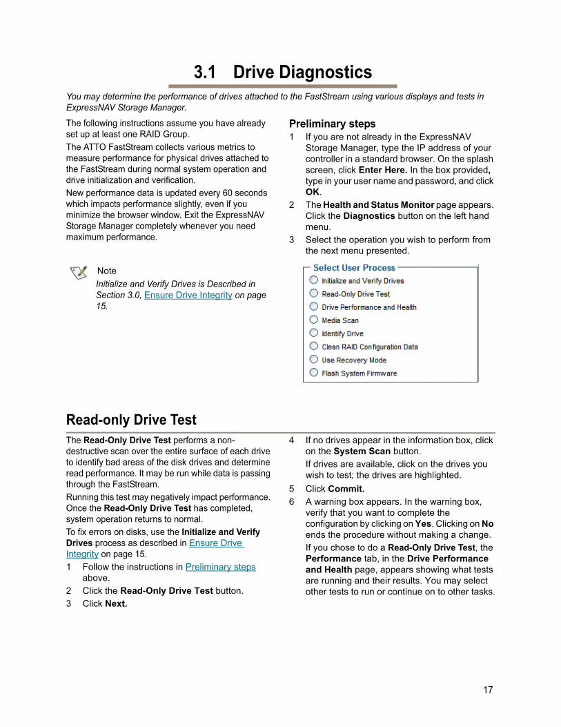
2 The Health and Status Monitor page appears. Click the Diagnostics button on the left hand menu.
3 Select the operation you wish to perform from the next menu presented.
Read-only Drive TestThe Read-Only Drive Test performs a non-destructive scan over the entire surface of each drive to identify bad areas of the disk drives and determine read performance. It may be run while data is passing through the FastStream.
Running this test may negatively impact performance. Once the Read-Only Drive Test has completed, system operation returns to normal.
To fix errors on disks, use the Initialize and Verify Drives process as described in Ensure Drive Integrity on page 15.
1 Follow the instructions in Preliminary steps above.
2 Click the Read-Only Drive Test button.
3 Click Next.
4 If no drives appear in the information box, click on the System Scan button.
If drives are available, click on the drives you wish to test; the drives are highlighted.
5 Click Commit.
6 A warning box appears. In the warning box, verify that you want to complete the configuration by clicking on Yes. Clicking on No ends the procedure without making a change.
If you chose to do a Read-Only Drive Test, the Performance tab, in the Drive Performance and Health page, appears showing what tests are running and their results. You may select other tests to run or continue on to other tasks.
17
Drive performance and healthAnother way to determine your drives’ status is to follow the instructions in Preliminary steps on page 17, and click on the Drive Performance and Health menu item.
1 Follow the instructions in Preliminary steps above.
2 Click on the Drive Performance and Health menu item.
3 The Drive Performance and Health (Performance Tab) page appears.
• Click on Show Help Text and Drives for an alternative view of the test progress.
• During the tests the Time Remaining box tells you how much time remains until the verification process is complete. The
representation of each drive in the Drives box shows the percentage of verification completed.
• Drive performance is displayed under the Drive Metrics section.
• Drive errors are displayed in the Drive Errors section of the page.
4 When the test is complete, click on each drive to see its information highlighted in the Drive Metrics window.
If you close the browser or navigate away from this page, you may re-access these results by clicking the Diagnostics button and choosing the Drive Performance and Health option. Results are available until the FastStream is restarted.
Identifying a drive attached to the FastStreamUse identify drive to replace the correct failed drive that has failed in a RAID group. Removing the wrong drive can have adverse effects to RAID group data.
CAUTIONCAUTION
Executing this command adversely impacts performance and throughput for the time that the LED is illuminated. If SES is available, it will take the user to the Identify SES Elements page described in Section 6.2 SCSI Enclosure Services (SES) on page 32. If SES is not available, it
will take the user to the standard Identify Drive page.
1 Follow the instructions in Preliminary steps on page 17.
2 Click on Identify Drive.
3 The Identify Drive page appears. Click on the box representing the drive you wish to identify. Only one drive may be selected at a time.
4 Click Commit. The I/O LED of the drive illuminates for one minute.
5 To stop the operation, deselect the drive.
18ATTO Technology Inc. FastStream SC Installation and Operation Manual
3.2 DriveAssureDriveAssure™ is an ATTO exclusive combination of features that perform predictive and corrective actions to allow the continued operation of marginal drives, while ensuring continued, uninterrupted access to data. DriveAssure lets your storage run longer, faster and smoother without interrupting data flow while avoiding the unnecessary cost of replacing functional drives.
There are six different technologies which make up DriveAssure feature:
• Guaranteed Latency Response
• Rebuilds Continue on Error
• Initialization Media Scrubbing
• Media Scan + Parity Verification
• On-the-Fly Media Error Handling
• Data Recovery Mode
Guaranteed LatencyIf there is a slow drive in a storage array, or an intermittently slow drive, or if a drive has a "slow spot", without extra processing this results in larger than usual delays. FastStream with DriveAssure™ technology, for parity and redundant RAID levels, compensate when one drive in a RAID Group does not respond within a specified period of time. The data from the drive can be generated using the parity or redundancy information from the rest of the RAID Group, with only a nominal change in throughput. In that way, the FastStream is forgiving of intermittent problems and can keep data moving smoothly.
Rebuild Continue on ErrorIn the event of a soft failure on a drive during a RAID Group rebuild, the FastStream will fix the drive issue, if possible, and continue the rebuild. This will allow rebuilds that occur overnight, during a holiday, or on a weekend, to continue providing additional protection against subsequent drive failures while unattended.
Initialization Media ScrubbingInitialization Media Scrubbing is performed during Advanced Initialization. When new drives are connected to the FastStream for the first time, it is recommended that they go through Advanced Initialization. FastStream will write a pattern, completely, on all drives and reassign access to any blocks reported as bad and also attempt to fix any soft errors. This provides the most reliable media to create RAID Groups.
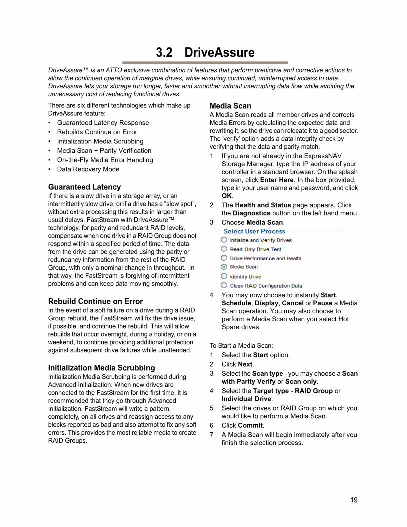
Media ScanA Media Scan reads all member drives and corrects Media Errors by calculating the expected data and rewriting it, so the drive can relocate it to a good sector. The 'verify' option adds a data integrity check by verifying that the data and parity match.
1 If you are not already in the ExpressNAV Storage Manager, type the IP address of your controller in a standard browser. On the splash screen, click Enter Here. In the box provided, type in your user name and password, and click OK.
2 The Health and Status page appears. Click the Diagnostics button on the left hand menu.
3 Choose Media Scan.
4 You may now choose to instantly Start, Schedule, Display, Cancel or Pause a Media Scan operation. You may also choose to perform a Media Scan when you select Hot Spare drives.
To Start a Media Scan:
1 Select the Start option.
2 Click Next.
3 Select the Scan type - you may choose a Scan with Parity Verify or Scan only.
4 Select the Target type - RAID Group or Individual Drive.
5 Select the drives or RAID Group on which you would like to perform a Media Scan.
6 Click Commit.
7 A Media Scan will begin immediately after you finish the selection process.
19
To Display Status, Cancel or Pause a Media Scan:
1 Select the Display, Cancel, Pause option.
2 Click Next.
3 Choose the appropriate setting to check on the status and to cancel or pause your Media Scan
To Schedule a Media Scan:
1 Select the Schedule option.
2 Click Next.
3 Select the Add Task button.
4 Enter the Media Scan type.
5 Enter the drives or RAID Group on which you would like to schedule a Media Scan.
6 Enter the frequency, date and time to schedule the Media Scan.
7 Click Commit.
Note
Enter time, day of week and 'daily' or 'weekly' to schedule a scan on a recurring basis.You may also view, reschedule and delete scheduled Media Scan events on this page.
On-the-Fly Media Error HandlingIf a media error occurs on a drive during normal data transfers, the FastStream will reassign these blocks as well as attempt to fix soft errors during normal read and write data transfer operations.
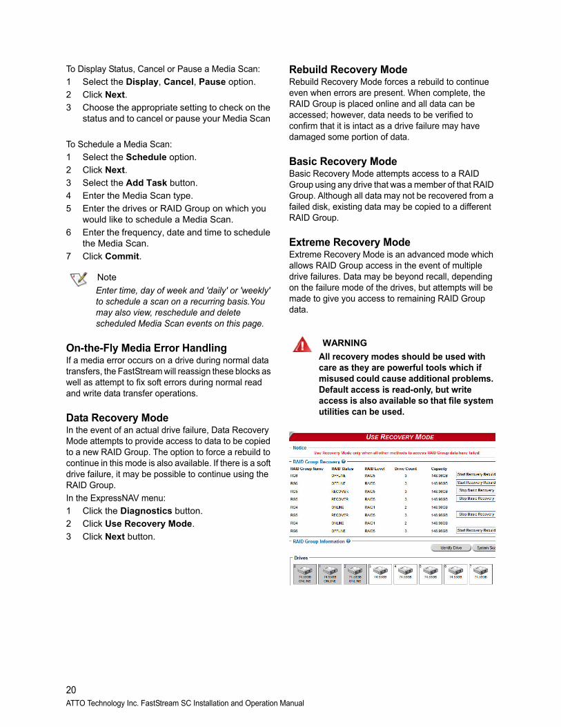
Data Recovery ModeIn the event of an actual drive failure, Data Recovery Mode attempts to provide access to data to be copied to a new RAID Group. The option to force a rebuild to continue in this mode is also available. If there is a soft drive failure, it may be possible to continue using the RAID Group.
In the ExpressNAV menu:
1 Click the Diagnostics button.
2 Click Use Recovery Mode.
3 Click Next button.
Rebuild Recovery ModeRebuild Recovery Mode forces a rebuild to continue even when errors are present. When complete, the RAID Group is placed online and all data can be accessed; however, data needs to be verified to confirm that it is intact as a drive failure may have damaged some portion of data.
Basic Recovery ModeBasic Recovery Mode attempts access to a RAID Group using any drive that was a member of that RAID Group. Although all data may not be recovered from a failed disk, existing data may be copied to a different RAID Group.
Extreme Recovery ModeExtreme Recovery Mode is an advanced mode which allows RAID Group access in the event of multiple drive failures. Data may be beyond recall, depending on the failure mode of the drives, but attempts will be made to give you access to remaining RAID Group data.
WARNING
All recovery modes should be used with care as they are powerful tools which if misused could cause additional problems. Default access is read-only, but write access is also available so that file system utilities can be used.
20ATTO Technology Inc. FastStream SC Installation and Operation Manual
4.0 Configure Storage into RAID GroupsThe ATTO FastStream allows configuration of storage into DVRAID, JBOD, RAID Level 0, 1, 1+0, 4, 5 or 6 with the ability to create multiple partitions.
RAID is a storage configuration which uses multiple drives to increase capacity, performance, and/or reliability. The FastStream can automatically set up an application-ready RAID configuration. Also, you may custom design a RAID configuration, or combine a custom and an automatic configuration.
The FastStream uses all available drives when you select Digital Video, Audio, General IT, or Database. Available drives include those which are on-line and not currently configured for RAID or Hot Spares.
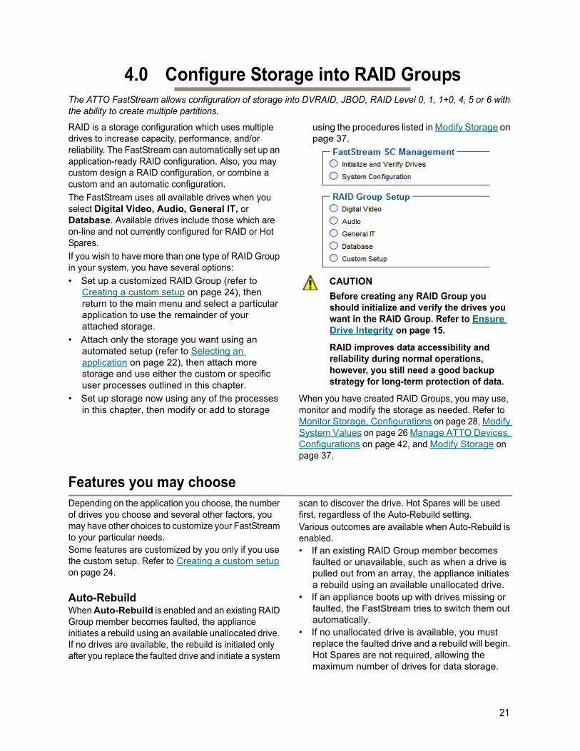
If you wish to have more than one type of RAID Group in your system, you have several options:
• Set up a customized RAID Group (refer to Creating a custom setup on page 24), then return to the main menu and select a particular application to use the remainder of your attached storage.
• Attach only the storage you want using an automated setup (refer to Selecting an application on page 22), then attach more storage and use either the custom or specific user processes outlined in this chapter.
• Set up storage now using any of the processes in this chapter, then modify or add to storage
using the procedures listed in Modify Storage on page 37.
CAUTIONCAUTION
Before creating any RAID Group you should initialize and verify the drives you want in the RAID Group. Refer to Ensure Drive Integrity on page 15.
RAID improves data accessibility and reliability during normal operations, however, you still need a good backup strategy for long-term protection of data.
When you have created RAID Groups, you may use, monitor and modify the storage as needed. Refer to Monitor Storage, Configurations on page 28, Modify System Values on page 26 Manage ATTO Devices, Configurations on page 42, and Modify Storage on page 37.
Features you may choose Depending on the application you choose, the number of drives you choose and several other factors, you may have other choices to customize your FastStream to your particular needs. Some features are customized by you only if you use the custom setup. Refer to Creating a custom setup on page 24.
Auto-RebuildWhen Auto-Rebuild is enabled and an existing RAID Group member becomes faulted, the appliance initiates a rebuild using an available unallocated drive. If no drives are available, the rebuild is initiated only after you replace the faulted drive and initiate a system
scan to discover the drive. Hot Spares will be used first, regardless of the Auto-Rebuild setting. Various outcomes are available when Auto-Rebuild is enabled.• If an existing RAID Group member becomes
faulted or unavailable, such as when a drive is pulled out from an array, the appliance initiates a rebuild using an available unallocated drive.
• If an appliance boots up with drives missing or faulted, the FastStream tries to switch them out automatically.
• If no unallocated drive is available, you must replace the faulted drive and a rebuild will begin. Hot Spares are not required, allowing the maximum number of drives for data storage.
21
However, if you require maximum fault tolerance, it is best practice to have a Hot Spare available to supply the unallocated drive for immediate use. Refer to FastStream process: adding or removing Hot Spares on page 40.
Fault ToleranceChoose either Standard Fault Tolerance (no Hot Spare drives) or Maximum Fault Tolerance (which adds Hot Spares to the system). Refer to FastStream process: adding or removing Hot Spares on page 40 for details.
Initialization If you have not already initialized your drives as outlined in Ensure Drive Integrity on page 15, you
may choose to use the Advanced Initialization for new drives to erase and verify drive media and correct some soft drive errors. The RAID Group is unavailable until the operation completes. Choose Express Initialization to perform a quick background initialization if you have already completed a full initialize and verify operation. The RAID Group being initialized is available for use during express initialization.
Note
For RAID levels other than RAID 4,5 or 6, “None” is the displayed option instead of “Express”
Selecting an applicationAfter initializing drives or setting up new storage, select an application from the Initial Setup or via the Manage page. The FastStream finds all available drives and creates the appropriate setup using those drives.
The most flexible choice is to use Custom Setup, but you must understand your needs and your system well to use this option.
Refer to Design RAID Groups on page i of Appendix A for more information about RAID.
Preliminary steps1 If you are not already in the ExpressNAV
Storage Manager, type the IP address of your appliance in a standard browser. On the splash screen, click Enter Here. In the box provided, type in your user name and password, and click OK.
2 If you have not performed the steps detailed in Ensure Drive Integrity on page 15 or created other RAID Groups, the Initial Setup Menu appears.
If you have initialized your storage or created other RAID configurations,
a. From the selections at the left, select Manage.
b. Click on the RAID Groups arrow.
c. Click on Create Group.
d. Click on Next.
3 Select one of the following and continue using the directions in each specific section:
Note
DVRAID is only available using the Digital Video setup wizard.
• Digital Video: provides parity RAID protection for digital applications for configurations using three or more drives.
• Audio: Audio track streaming technology provides parity RAID protection while managing latency to allow high-speed availability to support up to 192 tracks of 16-bit audio or 96 tracks of 24-bit audio in a single editing session.
• General IT: provides parity RAID protection optimized for random access applications using three or more drives.
• Database: provides parity RAID protection for database applications (small transfer, random access) for configurations using more than three drives.
Digital VideoAfter choosing Digital Video, the Setup Wizard page appears.
For the SC 8250 Only, Skip to Step 3.
Select your operating system.
1 This sets up multipathing support. If you chose Windows, click Yes and the system restarts. After the restart completes, continue to Step 7.
If you chose Mac, continue on to Step 7.
Physically add or disconnect drives as needed and rescan.
22ATTO Technology Inc. FastStream SC Installation and Operation Manual
2 Click Next.
3 Chose a RAID level.
4 Choose an Initialization method (refer to Initialization on page 22).
5 Choose an Auto-Rebuild option (refer to Auto-Rebuild on page 21).
6 Select a Fault Tolerance (refer to Fault Tolerance on page 22).
7 If all your drives do not appear in the Find Drives box, click on System Scan.
8 Click Commit.9 A warning box appears.
If you want to continue click Yes. The configuration completes and the Health and Status Monitor page appears.If you wish to start over, click No.The Setup Wizard page appears.
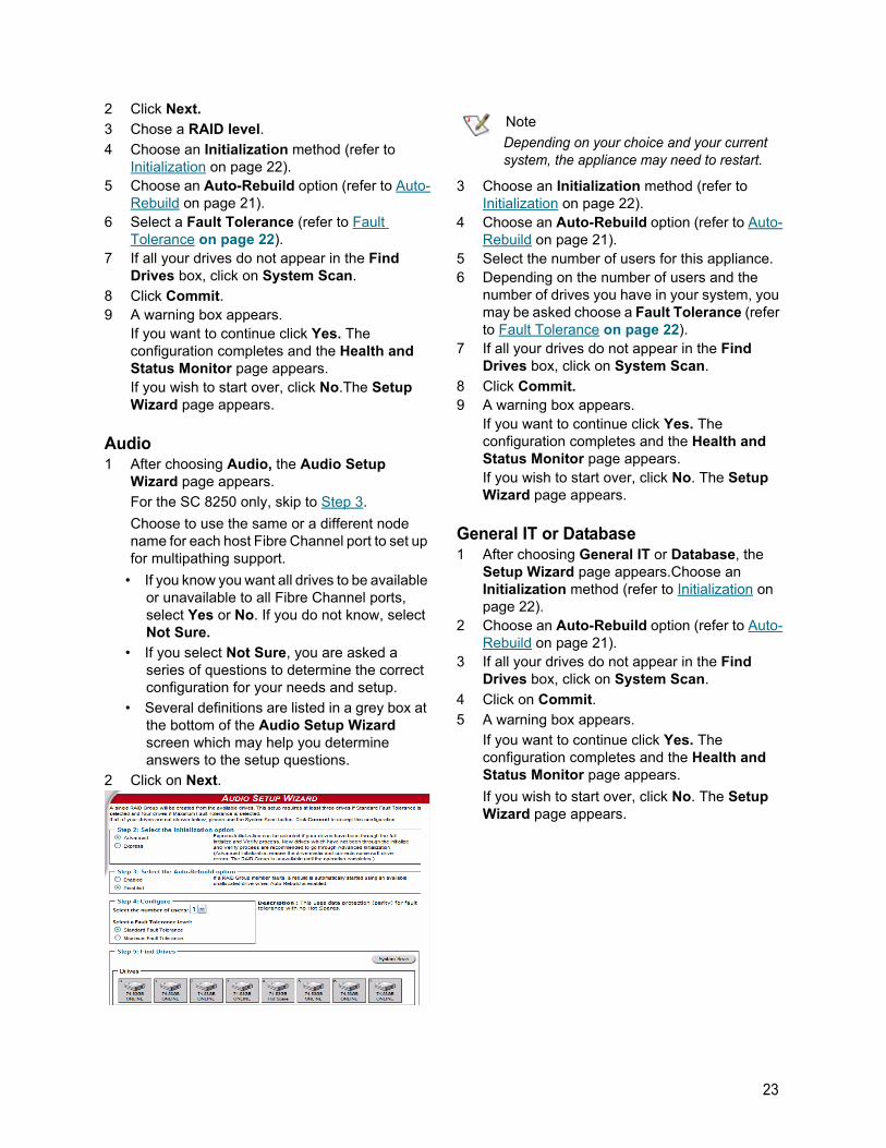
Audio1 After choosing Audio, the Audio Setup
Wizard page appears.
For the SC 8250 only, skip to Step 3.
Choose to use the same or a different node name for each host Fibre Channel port to set up for multipathing support.
• If you know you want all drives to be available or unavailable to all Fibre Channel ports, select Yes or No. If you do not know, select Not Sure.
• If you select Not Sure, you are asked a series of questions to determine the correct configuration for your needs and setup.
• Several definitions are listed in a grey box at the bottom of the Audio Setup Wizard screen which may help you determine answers to the setup questions.
2 Click on Next.
Note
Depending on your choice and your current system, the appliance may need to restart.
3 Choose an Initialization method (refer to Initialization on page 22).
4 Choose an Auto-Rebuild option (refer to Auto-Rebuild on page 21).
5 Select the number of users for this appliance.6 Depending on the number of users and the
number of drives you have in your system, you may be asked choose a Fault Tolerance (refer to Fault Tolerance on page 22).
7 If all your drives do not appear in the Find Drives box, click on System Scan.
8 Click Commit.9 A warning box appears.
If you want to continue click Yes. The configuration completes and the Health and Status Monitor page appears.If you wish to start over, click No. The Setup Wizard page appears.
General IT or Database1 After choosing General IT or Database, the
Setup Wizard page appears.Choose an Initialization method (refer to Initialization on page 22).
2 Choose an Auto-Rebuild option (refer to Auto-Rebuild on page 21).
3 If all your drives do not appear in the Find Drives box, click on System Scan.
4 Click on Commit.
5 A warning box appears.
If you want to continue click Yes. The configuration completes and the Health and Status Monitor page appears.
If you wish to start over, click No. The Setup Wizard page appears.
23
Creating a custom setupIf the application setups do not suit your needs, you may use Custom Setup to configure the FastStream.1 After choosing Custom Setup button, the
RAID Setup Wizard page appears. Click on Next.For SC 8250 Only, Skip to Step 3.
2 Decide if all drives are to be available to both ports.
• If you select Yes, the same node name is assigned to both ports and multipathing is supported.
• If you select No, different node names are assigned to each FC port.
• The choice you make establishes the access for all RAID Groups attached to this FastStream.
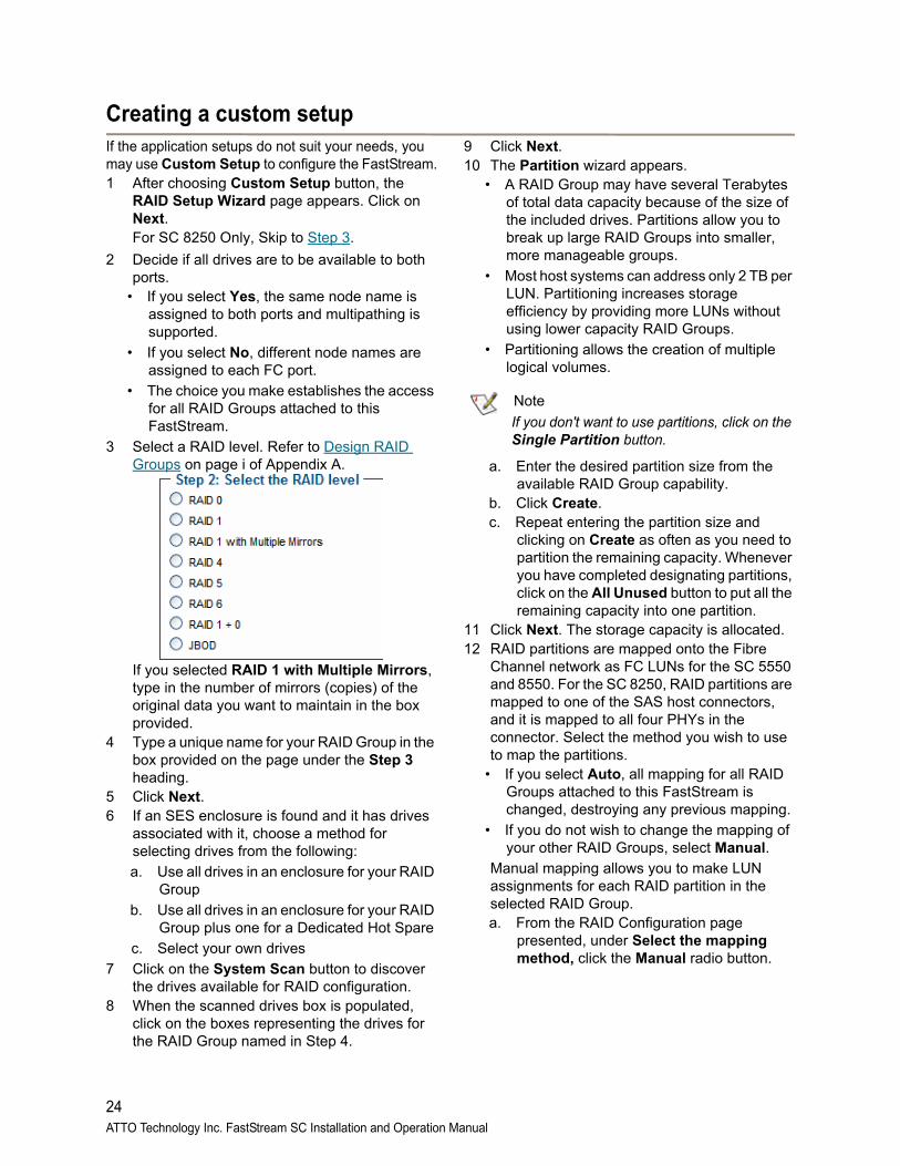
3 Select a RAID level. Refer to Design RAID Groups on page i of Appendix A.
If you selected RAID 1 with Multiple Mirrors, type in the number of mirrors (copies) of the original data you want to maintain in the box provided.
4 Type a unique name for your RAID Group in the box provided on the page under the Step 3 heading.
5 Click Next.6 If an SES enclosure is found and it has drives
associated with it, choose a method for selecting drives from the following:
a. Use all drives in an enclosure for your RAID Group
b. Use all drives in an enclosure for your RAID Group plus one for a Dedicated Hot Spare
c. Select your own drives
7 Click on the System Scan button to discover the drives available for RAID configuration.
8 When the scanned drives box is populated, click on the boxes representing the drives for the RAID Group named in Step 4.
9 Click Next.10 The Partition wizard appears.
• A RAID Group may have several Terabytes of total data capacity because of the size of the included drives. Partitions allow you to break up large RAID Groups into smaller, more manageable groups.
• Most host systems can address only 2 TB per LUN. Partitioning increases storage efficiency by providing more LUNs without using lower capacity RAID Groups.
• Partitioning allows the creation of multiple logical volumes.
Note
If you don't want to use partitions, click on the Single Partition button.
a. Enter the desired partition size from the available RAID Group capability.
b. Click Create. c. Repeat entering the partition size and
clicking on Create as often as you need to partition the remaining capacity. Whenever you have completed designating partitions, click on the All Unused button to put all the remaining capacity into one partition.
11 Click Next. The storage capacity is allocated.12 RAID partitions are mapped onto the Fibre
Channel network as FC LUNs for the SC 5550 and 8550. For the SC 8250, RAID partitions are mapped to one of the SAS host connectors, and it is mapped to all four PHYs in the connector. Select the method you wish to use to map the partitions.
• If you select Auto, all mapping for all RAID Groups attached to this FastStream is changed, destroying any previous mapping.
• If you do not wish to change the mapping of your other RAID Groups, select Manual.
Manual mapping allows you to make LUN assignments for each RAID partition in the selected RAID Group.
a. From the RAID Configuration page presented, under Select the mapping method, click the Manual radio button.
24ATTO Technology Inc. FastStream SC Installation and Operation Manual
b. For the SC 5550 and 8550, click on any partition to map that partition to a Port and LUN. For the SC 8250, click on any partition to map it to a connector and SAS LUN.
13 Click Next.
14 Choose an Initialization method (refer to Initialization on page 22).
15 Choose the Interleave by clicking on the drop down box.
CAUTIONCAUTION
The default value is usually best. Changing the default interleave size may degrade performance.
16 Select a Sector Size.The RAID Group sector size must be evenly divisible by the sector size of any member disk.
• 512 bytes is the default size for most operating systems.
• For Windows XP (32-bit support) select 4 KB sectors to enable large volume support (greater than 2 TB).
17 Select a SpeedRead feature. SpeedRead looks ahead during reads and stores the data in cache memory. The optimum setting depends on your actual I/O and storage. You may adjust this setting later.
• Enabling SpeedRead may boost performance when you are running video playback and other applications which access data sequentially.
• Disabling SpeedRead is a better choice for audio applications.
• SpeedRead Auto is usually the best choice for database applications.
18 Choose a Prefetch option--the number of extra stripes that are read when the SpeedRead setting is set to enabled or adaptive.
19 Choose an Auto-Rebuild feature if it is available for your RAID configuration (refer to Auto-Rebuild on page 21).
20 Choose a Rebuild Priority level. Rebuild Priority allows you to determine whether rebuild or I/O transactions take precedence during rebuild operations. If you choose low priority, for example, rebuilds take longer but the rebuild has minimal impact on performance.
21 Click on Next.22 A chart showing the setup you have selected
appears. If everything is the way you want it, click on Commit to save your configuration.
23 For RAID types that rebuild, a warning box tells you that all data on the attached disks is to be destroyed and the rebuild process is starting (may take several hours to complete). In the warning box, verify that you want to complete the configuration by clicking on Yes. Clicking on No ends the procedure without making a change.
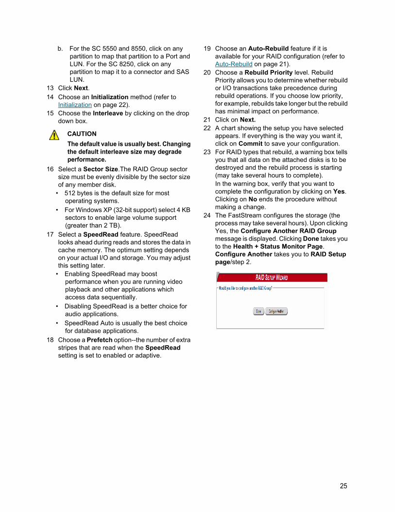
24 The FastStream configures the storage (the process may take several hours). Upon clicking Yes, the Configure Another RAID Group message is displayed. Clicking Done takes you to the Health + Status Monitor Page. Configure Another takes you to RAID Setup page/step 2.
25
5.0 Modify System ValuesDefault values are appropriate for most configurations, but may be modified for your needs using ATTO ExpressNAV Storage Manager.
It is best practice to change the default user name and password to a user name and password important to you. Other configurations may also be changed,
however, use extreme caution when changing default values.
Changing current user name, passwordIt is best practice to change the user name and password on all Telnet, FTP and ATTO ExpressNAV Storage Manager sessions. Refer to the CLI commands Username and Password in Appendix D.
1 Open a Command Line Interface session either using Telnet or the serial port as shown in Interface Options on page 45.
2 Type set UserName [name].
3 Press Enter.
4 Type set Password.
5 Press Enter.
6 Follow the instructions on the screen to confirm your old and new password.
Note
The user name is case insensitive and password is case sensitive.
The user name and password for all Telnet, FTP and ATTO ExpressNAV Storage Manager sessions is changed.
Creating a read-only user name, passwordYou may wish to set up a read-only user name and password to prevent changes to storage and FastStream settings. Refer to the CLI commands ReadOnlyPassword and ReadOnlyUsername in Appendix D.
1 Open a Command Line Interface session either using Telnet or the serial port as shown in Interface Options on page 45, or use the Advanced CLI page in an ExpressNAV Storage Manager session as shown on page 40.
2 Type set ReadOnlyUsername [name].
3 Press Enter.
4 Type set ReadOnlyPassword.
5 Press Enter.
6 Follow the instructions on the screen to confirm the read-only password.
The read-only user name and read-only password for all user interface sessions is changed.
Changing system variablesYou may change several system configurations to suit your needs.
1 If you are not already in the ExpressNAV Storage Manager, type the IP address of your controller in a standard browser, click Enter Here on the splash screen, then type in your user name and password in the box provided. Click OK.
2 Click on the Manage menu item on the left hand side of the page.
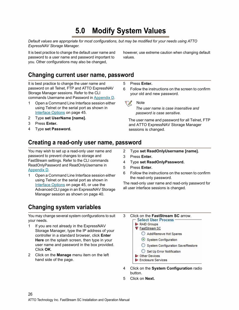
3 Click on the FastStream SC arrow.
4 Click on the System Configuration radio button.
5 Click on Next.
26ATTO Technology Inc. FastStream SC Installation and Operation Manual
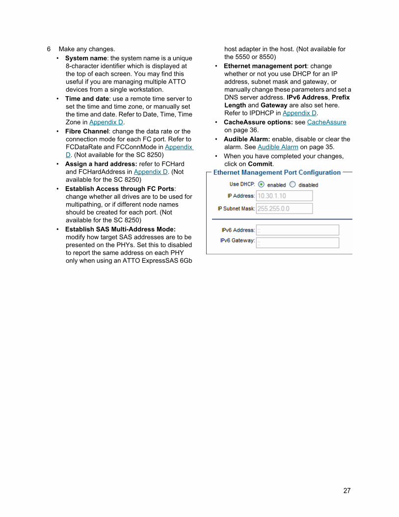
6 Make any changes.
• System name: the system name is a unique 8-character identifier which is displayed at the top of each screen. You may find this useful if you are managing multiple ATTO devices from a single workstation.
• Time and date: use a remote time server to set the time and time zone, or manually set the time and date. Refer to Date, Time, Time Zone in Appendix D.
• Fibre Channel: change the data rate or the connection mode for each FC port. Refer to FCDataRate and FCConnMode in Appendix D. (Not available for the SC 8250)
• Assign a hard address: refer to FCHard and FCHardAddress in Appendix D. (Not available for the SC 8250)
• Establish Access through FC Ports: change whether all drives are to be used for multipathing, or if different node names should be created for each port. (Not available for the SC 8250)
• Establish SAS Multi-Address Mode: modify how target SAS addresses are to be presented on the PHYs. Set this to disabled to report the same address on each PHY only when using an ATTO ExpressSAS 6Gb
host adapter in the host. (Not available for the 5550 or 8550)
• Ethernet management port: change whether or not you use DHCP for an IP address, subnet mask and gateway, or manually change these parameters and set a DNS server address. IPv6 Address, Prefix Length and Gateway are also set here. Refer to IPDHCP in Appendix D.
• CacheAssure options: see CacheAssure on page 36.
• Audible Alarm: enable, disable or clear the alarm. See Audible Alarm on page 35.
• When you have completed your changes, click on Commit.
27
6.0 Monitor Storage, ConfigurationsYou may determine the performance of drives attached to the FastStream using various displays and tests in ExpressNAV Storage Manager.
The following instructions assume you have already set up at least one RAID Group.
The ATTO FastStream collects various metrics to measure performance for physical drives attached to the FastStream during normal system operation and drive initialization and verification.
Note
New performance data is updated every 60 seconds which impacts performance slightly, even if you minimize the browser window. Exit the ExpressNAV Storage Manager completely whenever you need maximum performance.
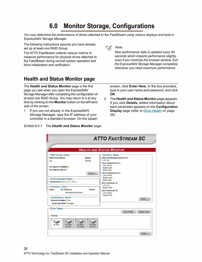
Health and Status Monitor pageThe Health and Status Monitor page is the first page you see when you open the ExpressNAV Storage Manager after completing the configuration of at least one RAID Group. You may return to it at any time by clicking on the Monitor button on the left hand side of the screen.
1 If you are not already in the ExpressNAV Storage Manager, type the IP address of your controller in a standard browser. On the splash
screen, click Enter Here. In the box provided, type in your user name and password, and click OK.
2 The Health and Status Monitor page appears. If you click Details, added information about each parameter appears on the Configuration Display page (refer to Drive Health on page 29).
Exhibit 6.0-1 The Health and Status Monitor page.
28ATTO Technology Inc. FastStream SC Installation and Operation Manual
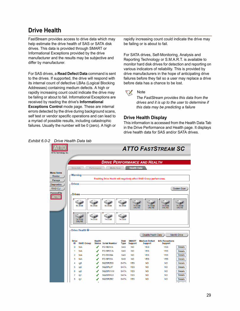
Drive HealthFastStream provides access to drive data which may help estimate the drive health of SAS or SATA disk drives. This data is provided through SMART or Informational Exceptions provided by the drive manufacturer and the results may be subjective and differ by manufacturer.
For SAS drives, a Read Defect Data command is sent to the drives. If supported, the drive will respond with its internal count of defective LBAs (Logical Blocking Addresses) containing medium defects. A high or rapidly increasing count could indicate the drive may be failing or about to fail. Informational Exceptions are received by reading the drive's Informational Exceptions Control mode page. These are internal errors detected by the drive during background scans, self test or vendor specific operations and can lead to a myriad of possible results, including catastrophic failures. Usually the number will be 0 (zero). A high or
rapidly increasing count could indicate the drive may be failing or is about to fail.
For SATA drives, Self-Monitoring, Analysis and Reporting Technology or S.M.A.R.T. is available to monitor hard disk drives for detection and reporting on various indicators of reliability. This is provided by drive manufacturers in the hope of anticipating drive failures before they fail so a user may replace a drive before data has a chance to be lost.
Note
The FastStream provides this data from the drives and it is up to the user to determine if this data may be predicting a failure
Drive Health DisplayThis information is accessed from the Health Data Tab in the Drive Performance and Health page. It displays drive health data for SAS and/or SATA drives.
Exhibit 6.0-2 Drive Health Data tab
29
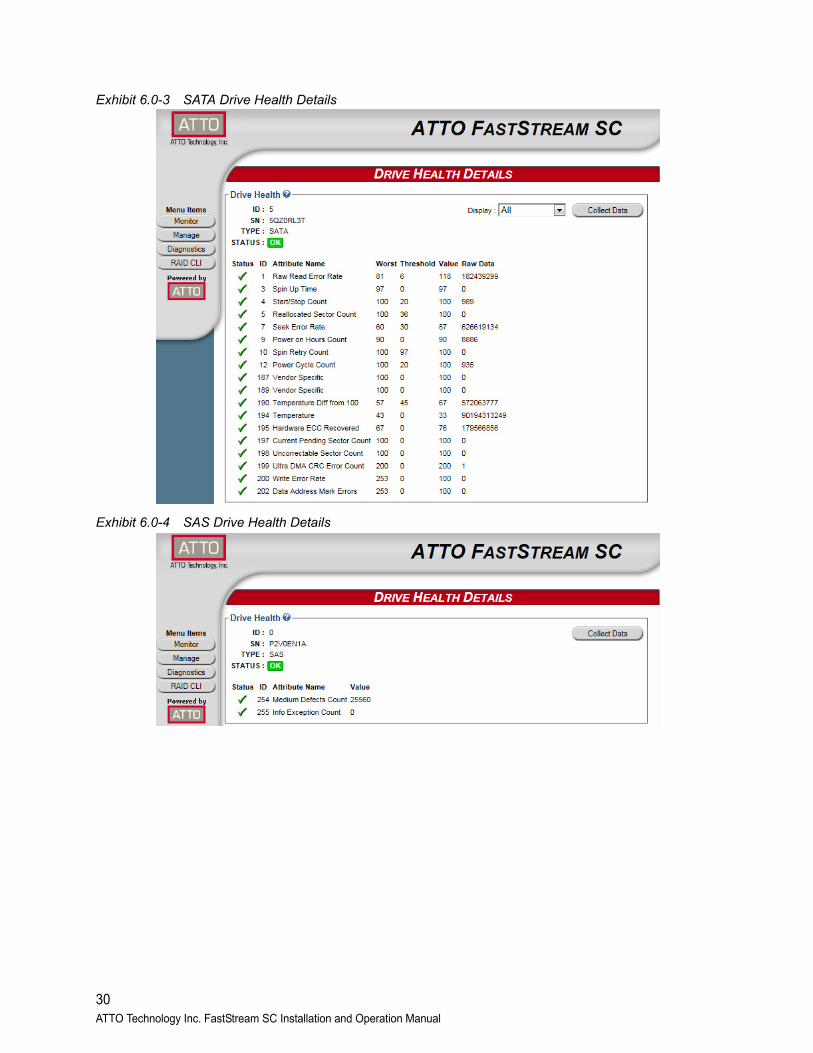
Exhibit 6.0-3 SATA Drive Health Details
Exhibit 6.0-4 SAS Drive Health Details
30ATTO Technology Inc. FastStream SC Installation and Operation Manual
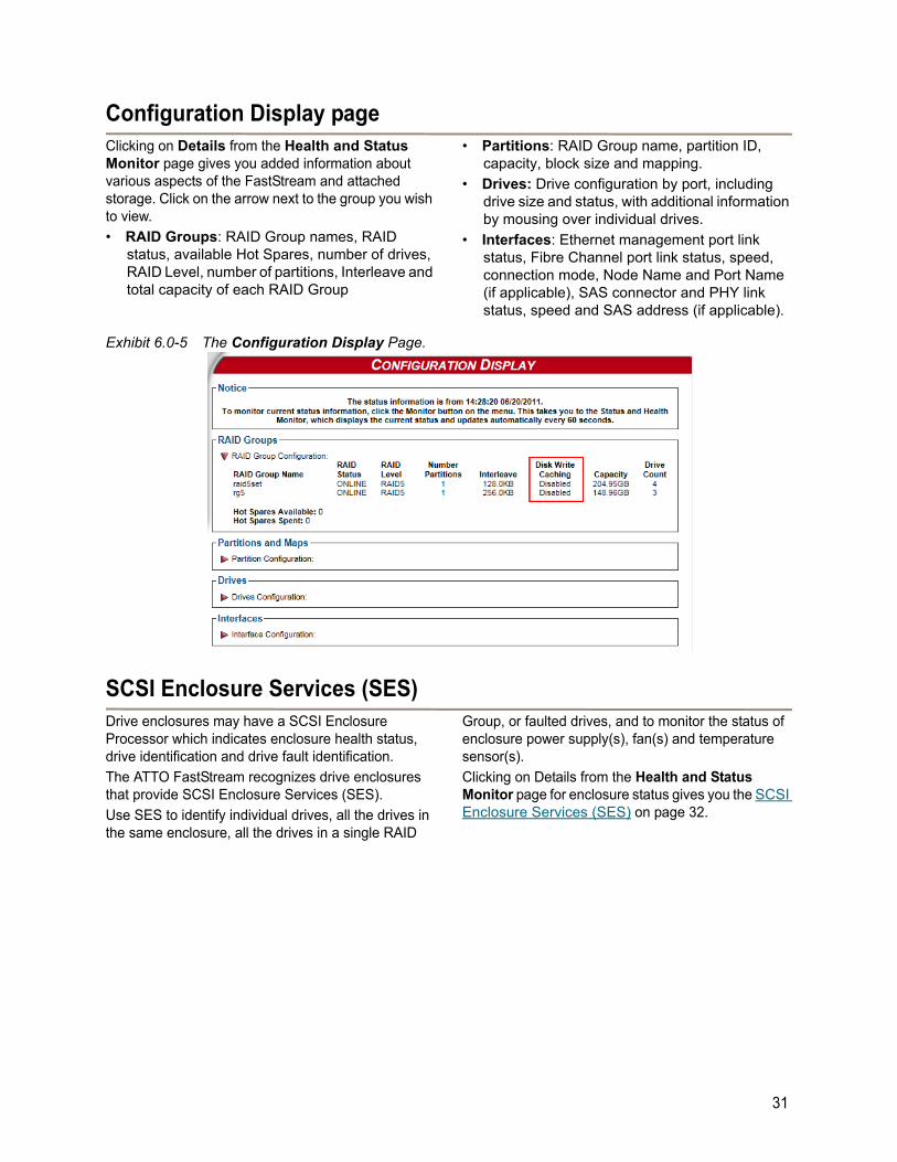
Configuration Display pageClicking on Details from the Health and Status Monitor page gives you added information about various aspects of the FastStream and attached storage. Click on the arrow next to the group you wish to view.
• RAID Groups: RAID Group names, RAID status, available Hot Spares, number of drives, RAID Level, number of partitions, Interleave and total capacity of each RAID Group
• Partitions: RAID Group name, partition ID, capacity, block size and mapping.
• Drives: Drive configuration by port, including drive size and status, with additional information by mousing over individual drives.
• Interfaces: Ethernet management port link status, Fibre Channel port link status, speed, connection mode, Node Name and Port Name (if applicable), SAS connector and PHY link status, speed and SAS address (if applicable).
Exhibit 6.0-5 The Configuration Display Page.
SCSI Enclosure Services (SES)Drive enclosures may have a SCSI Enclosure Processor which indicates enclosure health status, drive identification and drive fault identification.
The ATTO FastStream recognizes drive enclosures that provide SCSI Enclosure Services (SES).
Use SES to identify individual drives, all the drives in the same enclosure, all the drives in a single RAID
Group, or faulted drives, and to monitor the status of enclosure power supply(s), fan(s) and temperature sensor(s).
Clicking on Details from the Health and Status Monitor page for enclosure status gives you the SCSI Enclosure Services (SES) on page 32.
31
6.1 Remote System MonitoringYou may set up the FastStream to send notifications using Email when certain events occur.
You may set up the FastStream to send notifications when certain events occur using Error Notification page of the ExpressNAV Storage Manager.
You designate the person receiving notification of conditions and the level of severity which prompt notification using Email notification.
Types of errors• Device/drive errors such as medium error,
aborted command and hard error
• Device/drive transitions from online to offline
• Critical and warning temperature conditions
• Critical and warning voltage conditions
• Power recycle/power failure conditions
• Enclosure issues, when SES is Available
Warning messages• device down
• medium error
• abort command
Message severity levels • Critical: critical event Emails
• Warning: warnings and critical event Emails are sent
• Informational: information which you may want to know but which probably does not require action: only information messages are sent
• All: warnings, critical events and informational messages
• None: no Emails are sent
Email notificationPhone home Email notification allows the FastStream to send an Email message to you, a network administrator or other users when certain events occur with the FastStream.
Serious error messages are sent immediately, while messages for less serious errors are sent every 15 minutes.
You may send Emails to up to five Email addresses and designate which conditions prompt each Email notification.
For example, a recipient with a critical severity level only receives critical messages and not warning or informational messages.
When an event occurs that warrants Email notification, the FastStream sends the message; it cannot respond to a rejection by a server for an invalid address. Ensure all Email addresses typed in are valid.
Each Email is time stamped when it is sent as part of the SMTP header information.
1 If you are not already in the ExpressNAV Storage Manager, type the IP address of your controller in a standard browser. On the splash screen, click Enter Here. In the box provided, type in your user name and password, and click OK.
2 The Health and Status Monitor page appears. On the menu at the left hand side of the page, choose Manage.
3 The Manage Menu page appears. Click on the FastStream SC arrow.
4 Click the Set up Error Notification button.
5 Click Next.
6 Click on the Enabled button for Notification Configuration.
7 Type in the sender address or use the default. (Emails show this name in the From field).
8 Type or use the default SMTP Server (the Email server) IP address or the name of the SMTP server and, if required, the user name and password used to log into the server.
9 Type in up to five Email addresses.
10 Choose All, Critical, Warning, Informational or None for each Email address.
11 Click on the Send Test Email check box to test the entered settings.
12 When all information is typed in, click Commit.
30ATTO Technology Inc. FastStream SC Installation and Operation Manual
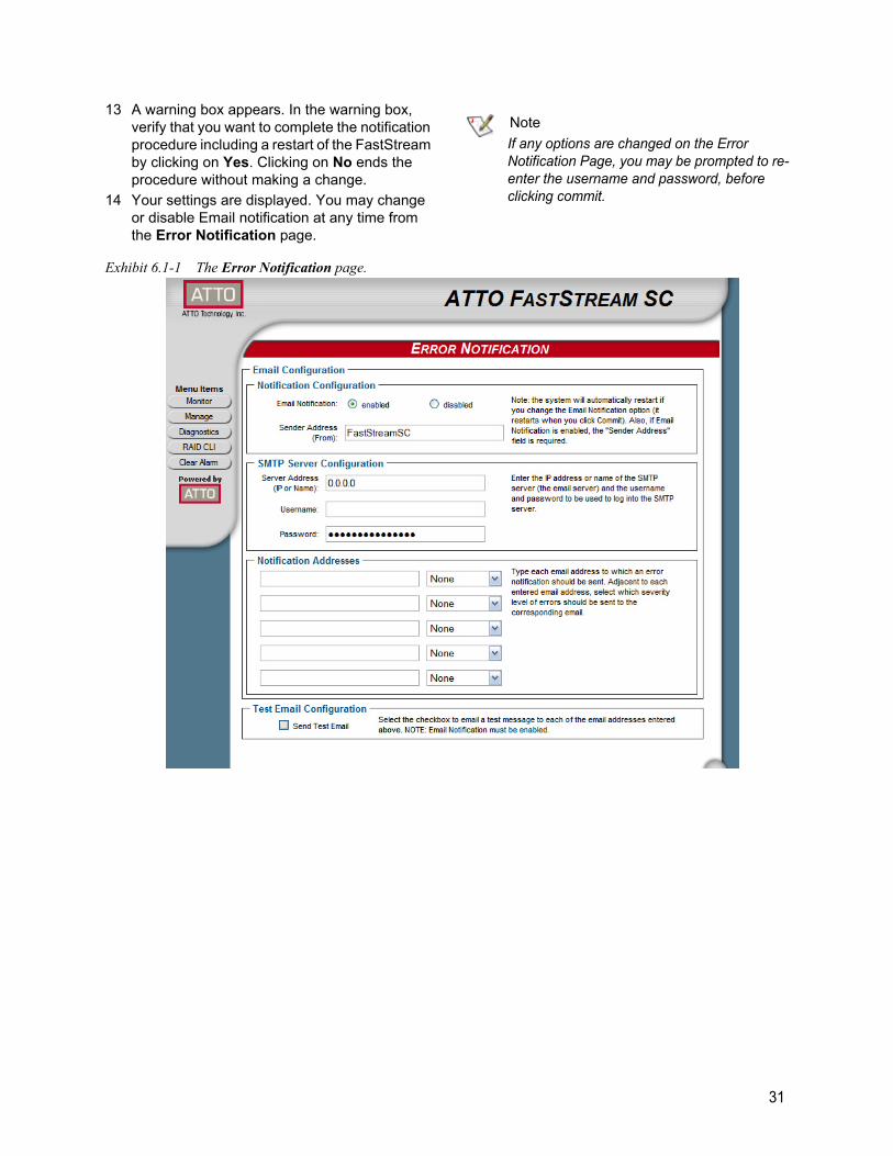
13 A warning box appears. In the warning box, verify that you want to complete the notification procedure including a restart of the FastStream by clicking on Yes. Clicking on No ends the procedure without making a change.
14 Your settings are displayed. You may change or disable Email notification at any time from the Error Notification page.
Note
If any options are changed on the Error Notification Page, you may be prompted to re-enter the username and password, before clicking commit.
Exhibit 6.1-1 The Error Notification page.
31
6.2 SCSI Enclosure Services (SES)Drive enclosures may provide a SCSI Enclosure Processor which indicates enclosure health status, drive identification and drive fault.
The ATTO Storage Controller recognizes drive enclosures that provide SCSI Enclosure Services (SES) information. You may use SES to identify
individual drives, all the drives in the same enclosure, all the drives in a single RAID Group, or faulted drives.
SES also provides status on power supplies, fans and thermal sensors in the attached enclosures.
Setting up SES1 If you are not already in the ExpressNAV
Storage Manager, type the IP address of your controller in a standard browser. On the splash screen, click Enter Here. In the box provided, type in your user name and password, and click OK.
2 The Health and Status Monitor page appears. Click on the Manage menu item on the left hand side of the screen.
3 Select Manage Enclosure Services.
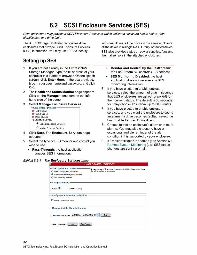
4 Click Next. The Enclosure Services page appears.
5 Select the type of SES monitor and control you wish to use.
• Pass-Through: the host application manages SES information.
• Monitor and Control by the FastStream: the FastStream SC controls SES services.
• SES Monitoring Disabled: the host application does not receive any SES monitoring information.
6 If you have elected to enable enclosure services, select the amount of time in seconds that SES enclosures are asked (or polled) for their current status. The default is 30 seconds: you may choose an interval up to 60 minutes.
7 If you have elected to enable enclosure services, and you want the enclosure to sound an alarm if a drive becomes faulted, select the box Enable Faulted Drive Alarm.
8 Choose to test an enclosure’s alarm or to mute alarms. You may also choose to have an occasional audible reminder of the alarm condition if it is supported by your enclosure.
9 If Email Notification is enabled (see Section 6.1, Remote System Monitoring ), all SES status changes are sent via email.
Exhibit 6.2-1 The Enclosure Services page.
32ATTO Technology Inc. FastStream SC Installation and Operation Manual
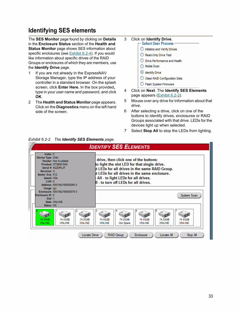
Identifying SES elementsThe SES Monitor page found by clicking on Details in the Enclosure Status section of the Health and Status Monitor page shows SES information about specific enclosures (see Exhibit 6.2-4). If you would like information about specific drives of the RAID Groups or enclosures of which they are members, use the Identify Drive page.
1 If you are not already in the ExpressNAV Storage Manager, type the IP address of your controller in a standard browser. On the splash screen, click Enter Here. In the box provided, type in your user name and password, and click OK.
2 The Health and Status Monitor page appears. Click on the Diagnostics menu on the left hand side of the screen.
3 Click on Identify Drive.
4 Click on Next. The Identify SES Elements page appears (Exhibit 6.2-2).
5 Mouse over any drive for information about that drive.
6 After selecting a drive, click on one of the buttons to identify drives, enclosures or RAID Groups associated with that drive. LEDs for the devices light up when selected.
7 Select Stop All to stop the LEDs from lighting.
Exhibit 6.2-2 The Identify SES Elements page.
33
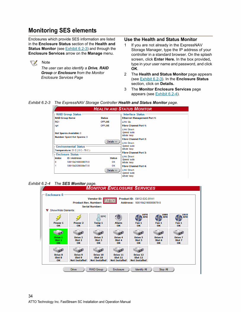
Monitoring SES elementsEnclosures which provide SES information are listed in the Enclosure Status section of the Health and Status Monitor (see Exhibit 6.2-3) and through the Enclosure Services arrow on the Manage menu.
Note
The user can also identify a Drive, RAID Group or Enclosure from the Monitor Enclosure Services Page
Use the Health and Status Monitor1 If you are not already in the ExpressNAV
Storage Manager, type the IP address of your controller in a standard browser. On the splash screen, click Enter Here. In the box provided, type in your user name and password, and click OK.
2 The Health and Status Monitor page appears (see Exhibit 6.2-3). In the Enclosure Status section, click on Details.
3 The Monitor Enclosure Services page appears (see Exhibit 6.2-4).
Exhibit 6.2-3 The ExpressNAV Storage Controller Health and Status Monitor page.
Exhibit 6.2-4 The SES Monitor page.
34ATTO Technology Inc. FastStream SC Installation and Operation Manual
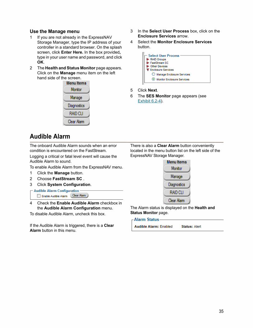
Use the Manage menu1 If you are not already in the ExpressNAV
Storage Manager, type the IP address of your controller in a standard browser. On the splash screen, click Enter Here. In the box provided, type in your user name and password, and click OK.
2 The Health and Status Monitor page appears. Click on the Manage menu item on the left hand side of the screen.
3 In the Select User Process box, click on the Enclosure Services arrow.
4 Select the Monitor Enclosure Services button.
5 Click Next.
6 The SES Monitor page appears (see Exhibit 6.2-4).
Audible AlarmThe onboard Audible Alarm sounds when an error condition is encountered on the FastStream.
Logging a critical or fatal level event will cause the Audible Alarm to sound.
To enable Audible Alarm from the ExpressNAV menu.
1 Click the Manage button.
2 Choose FastStream SC .
3 Click System Configuration.
4 Check the Enable Audible Alarm checkbox in the Audible Alarm Configuration menu.
To disable Audible Alarm, uncheck this box.
If the Audible Alarm is triggered, there is a Clear Alarm button in this menu.
There is also a Clear Alarm button conveniently located in the menu button list on the left side of the ExpressNAV Storage Manager.
The Alarm status is displayed on the Health and Status Monitor page.
35
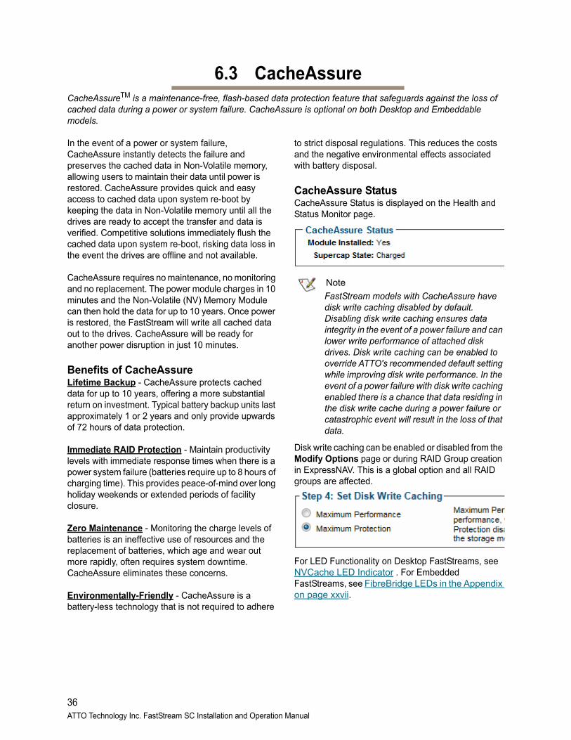
36ATTO Technology Inc. FastStream SC Installation and Operation Manual
6.3 CacheAssureCacheAssureTM is a maintenance-free, flash-based data protection feature that safeguards against the loss of cached data during a power or system failure. CacheAssure is optional on both Desktop and Embeddable models.
In the event of a power or system failure, CacheAssure instantly detects the failure and preserves the cached data in Non-Volatile memory, allowing users to maintain their data until power is restored. CacheAssure provides quick and easy access to cached data upon system re-boot by keeping the data in Non-Volatile memory until all the drives are ready to accept the transfer and data is verified. Competitive solutions immediately flush the cached data upon system re-boot, risking data loss in the event the drives are offline and not available.
CacheAssure requires no maintenance, no monitoring and no replacement. The power module charges in 10 minutes and the Non-Volatile (NV) Memory Module can then hold the data for up to 10 years. Once power is restored, the FastStream will write all cached data out to the drives. CacheAssure will be ready for another power disruption in just 10 minutes.
Benefits of CacheAssureLifetime Backup - CacheAssure protects cached data for up to 10 years, offering a more substantial return on investment. Typical battery backup units last approximately 1 or 2 years and only provide upwards of 72 hours of data protection.
Immediate RAID Protection - Maintain productivity levels with immediate response times when there is a power system failure (batteries require up to 8 hours of charging time). This provides peace-of-mind over long holiday weekends or extended periods of facility closure.
Zero Maintenance - Monitoring the charge levels of batteries is an ineffective use of resources and the replacement of batteries, which age and wear out more rapidly, often requires system downtime. CacheAssure eliminates these concerns.
Environmentally-Friendly - CacheAssure is a battery-less technology that is not required to adhere
to strict disposal regulations. This reduces the costs and the negative environmental effects associated with battery disposal.
CacheAssure Status CacheAssure Status is displayed on the Health and Status Monitor page.
Note
FastStream models with CacheAssure have disk write caching disabled by default. Disabling disk write caching ensures data integrity in the event of a power failure and can lower write performance of attached disk drives. Disk write caching can be enabled to override ATTO's recommended default setting while improving disk write performance. In the event of a power failure with disk write caching enabled there is a chance that data residing in the disk write cache during a power failure or catastrophic event will result in the loss of that data.
Disk write caching can be enabled or disabled from the Modify Options page or during RAID Group creation in ExpressNAV. This is a global option and all RAID groups are affected.
For LED Functionality on Desktop FastStreams, see NVCache LED Indicator . For Embedded FastStreams, see FibreBridge LEDs in the Appendix on page xxvii.
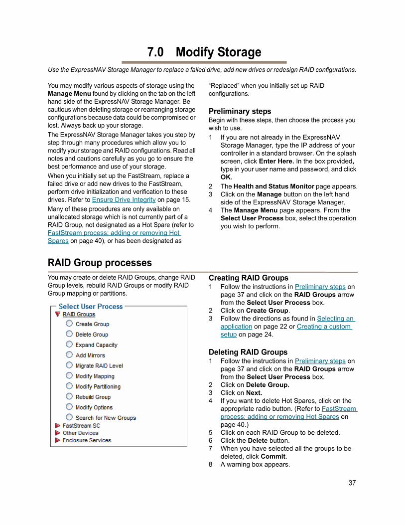
7.0 Modify StorageUse the ExpressNAV Storage Manager to replace a failed drive, add new drives or redesign RAID configurations.
You may modify various aspects of storage using the Manage Menu found by clicking on the tab on the left hand side of the ExpressNAV Storage Manager. Be cautious when deleting storage or rearranging storage configurations because data could be compromised or lost. Always back up your storage.
The ExpressNAV Storage Manager takes you step by step through many procedures which allow you to modify your storage and RAID configurations. Read all notes and cautions carefully as you go to ensure the best performance and use of your storage.
When you initially set up the FastStream, replace a failed drive or add new drives to the FastStream, perform drive initialization and verification to these drives. Refer to Ensure Drive Integrity on page 15.
Many of these procedures are only available on unallocated storage which is not currently part of a RAID Group, not designated as a Hot Spare (refer to FastStream process: adding or removing Hot Spares on page 40), or has been designated as
“Replaced” when you initially set up RAID configurations.
Preliminary stepsBegin with these steps, then choose the process you wish to use.
1 If you are not already in the ExpressNAV Storage Manager, type the IP address of your controller in a standard browser. On the splash screen, click Enter Here. In the box provided, type in your user name and password, and click OK.
2 The Health and Status Monitor page appears.3 Click on the Manage button on the left hand
side of the ExpressNAV Storage Manager.4 The Manage Menu page appears. From the
Select User Process box, select the operation you wish to perform.
RAID Group processesYou may create or delete RAID Groups, change RAID Group levels, rebuild RAID Groups or modify RAID Group mapping or partitions.
Creating RAID Groups1 Follow the instructions in Preliminary steps on
page 37 and click on the RAID Groups arrow from the Select User Process box.
2 Click on Create Group.3 Follow the directions as found in Selecting an
application on page 22 or Creating a custom setup on page 24.
Deleting RAID Groups1 Follow the instructions in Preliminary steps on
page 37 and click on the RAID Groups arrow from the Select User Process box.
2 Click on Delete Group.3 Click on Next.4 If you want to delete Hot Spares, click on the
appropriate radio button. (Refer to FastStream process: adding or removing Hot Spares on page 40.)
5 Click on each RAID Group to be deleted.6 Click the Delete button.7 When you have selected all the groups to be
deleted, click Commit.8 A warning box appears.
37
If you want to continue click Yes. The configuration completes and the Health and Status Monitor page appears.
If you wish to start over, click No.
Adding drives to a RAID GroupIf you have unallocated drives, you can increase the number of drives used by an existing RAID Group by adding an unallocated drive to the group. The new drive is set up in a separate partition within the RAID Group. You may have to add more than one drive depending on the RAID Group setup.
1 Follow the instructions in Preliminary steps on page 37 and click on the RAID Groups arrow from the Select User Process box.
2 Click on Expand Capacity. 3 Click Next. 4 Select the RAID Group you wish to add the
drives to from the drop down menu. 5 Click on the drives you wish to add to your RAID
Group.
CAUTIONCAUTION
Adding drives to an existing RAID Group may adversely impact performance. You cannot reverse this operation unless you delete the RAID Group.
6 When you have completed your changes, click on Commit.
7 A warning box appears noting that information on the added drives is erased. Back up all data on the new disks before proceeding. In the warning box, verify that you want to complete the configuration by clicking on Yes. Clicking on No ends the procedure without making a change.
8 The Health and Status Monitor page appears.9 Depending on how the drives are added, when
the process completes, the added drives may be in a separate, new partition within the RAID Group
Adding mirrors to a RAID configurationTo increase data protection in RAID Level 1 groups, you may add additional mirrors from unallocated storage. Also known as n-way mirroring, adding mirrors can only be performed if no other Add Drives, Add Mirror or RAID Migration operations are being performed.
1 Follow the instructions in Preliminary steps on page 37 and click on the RAID Groups arrow from the Select User Process box.
2 Click on Add Mirrors. 3 Click Next. 4 Select the RAID Level 1 group you wish to add
the mirror drive to from the drop down menu. 5 Select the drive you wish to add.
CAUTIONCAUTION
Adding drives to an existing RAID Group may adversely impact performance. You cannot reverse this operation unless you delete the RAID Group.
6 When you have completed your changes, click on Commit.
7 A warning box appears. In the warning box, verify that you want to complete the configuration by clicking on Yes. Clicking on No ends the procedure without making a change.
8 The Health and Status Monitor page appears.
Changing RAID configuration: RAID migrationIf you have unallocated drives, you can use them to change the RAID Level of an existing RAID Group. The following migration levels are supported:
• JBOD to RAID Level 0
• JBOD to RAID Level 1
• RAID Level 0 to RAID Level1+0
• RAID Level 1 to RAID1+0
1 Follow the instructions in Preliminary steps on page 37 and click on the RAID Groups arrow from the Select User Process box.
2 Click on the Migrate RAID Level button.3 Click on Next.4 Follow the on-screen directions.
CAUTIONCAUTION
Adding drives to an existing RAID Group may adversely impact performance. You cannot reverse this operation unless you delete the RAID Group.
5 When you have made your changes, click on Commit.
6 A warning box appears. In the warning box, verify that you want to complete the configuration by clicking on Yes. Clicking on No ends the procedure without making a change.
7 The Health and Status Monitor page appears.
38ATTO Technology Inc. FastStream SC Installation and Operation Manual
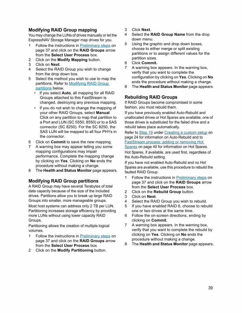
Modifying RAID Group mappingYou may change the LUNs of drives manually or let the ExpressNAV Storage Manager map drives for you.
1 Follow the instructions in Preliminary steps on page 37 and click on the RAID Groups arrow from the Select User Process box.
2 Click on the Modify Mapping button.3 Click on Next.4 Select the RAID Group you wish to change
from the drop down box.5 Select the method you wish to use to map the
partitions. Refer to Modifying RAID Group partitions below.
• If you select Auto, all mapping for all RAID Groups attached to this FastStream is changed, destroying any previous mapping.
• If you do not wish to change the mapping of your other RAID Groups, select Manual. Click on any partition to map that partition to a Port and LUN (SC 5550, 8550) or to a SAS connector (SC 8250). For the SC 8250, the SAS LUN will be mapped to all four PHYs in the connector.
6 Click on Commit to save the new mapping.7 A warning box may appear telling you some
mapping configurations may impair performance. Complete the mapping change by clicking on Yes. Clicking on No ends the procedure without making a change.
8 The Health and Status Monitor page appears.
Modifying RAID Group partitionsA RAID Group may have several Terabytes of total data capacity because of the size of the included drives. Partitions allow you to break up large RAID Groups into smaller, more manageable groups.
Most host systems can address only 2 TB per LUN. Partitioning increases storage efficiency by providing more LUNs without using lower capacity RAID Groups.
Partitioning allows the creation of multiple logical volumes.
1 Follow the instructions in Preliminary steps on page 37 and click on the RAID Groups arrow from the Select User Process box.
2 Click on the Modify Partitioning button.
3 Click Next.4 Select the RAID Group Name from the drop
down menu.5 Using the graphic and drop down boxes,
choose to either merge or split existing partitions or to assign different values for the partition sizes.
6 Click Commit.7 A warning box appears. In the warning box,
verify that you want to complete the configuration by clicking on Yes. Clicking on No ends the procedure without making a change.
8 The Health and Status Monitor page appears.
Rebuilding RAID GroupsIf RAID Groups become compromised in some fashion, you must rebuild them.
If you have previously enabled Auto-Rebuild and unallocated drives or Hot Spares are available, one of those drives is substituted for the failed drive and a rebuild takes place automatically.
Refer to Step 19 under Creating a custom setup on page 24 for information on Auto-Rebuild and to FastStream process: adding or removing Hot Spares on page 40 for information on Hot Spares.
Hot Spares, if available, are used first, regardless of the Auto-Rebuild setting.
If you have not enabled Auto-Rebuild and no Hot Spares are available, use this procedure to rebuild the faulted RAID Group.
1 Follow the instructions in Preliminary steps on page 37 and click on the RAID Groups arrow from the Select User Process box.
2 Click on the Rebuild Group button.3 Click on Next.4 Select the RAID Group you wish to rebuild.5 If you have enabled RAID 6, choose to rebuild
one or two drives at the same time.6 Follow the on-screen directions, ending by
clicking on Commit. 7 A warning box appears. In the warning box,
verify that you want to complete the rebuild by clicking on Yes. Clicking on No ends the procedure without making a change.
8 The Health and Status Monitor page appears.
39
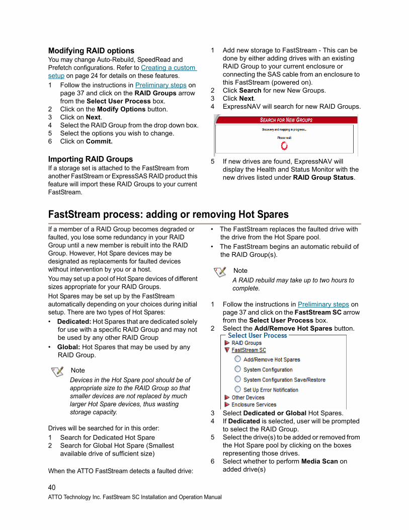
Modifying RAID optionsYou may change Auto-Rebuild, SpeedRead and Prefetch configurations. Refer to Creating a custom setup on page 24 for details on these features.
1 Follow the instructions in Preliminary steps on page 37 and click on the RAID Groups arrow from the Select User Process box.
2 Click on the Modify Options button.3 Click on Next.4 Select the RAID Group from the drop down box.5 Select the options you wish to change. 6 Click on Commit.
Importing RAID GroupsIf a storage set is attached to the FastStream from another FastStream or ExpressSAS RAID product this feature will import these RAID Groups to your current FastStream.
1 Add new storage to FastStream - This can be done by either adding drives with an existing RAID Group to your current enclosure or connecting the SAS cable from an enclosure to this FastStream (powered on).
2 Click Search for new New Groups.3 Click Next.4 ExpressNAV will search for new RAID Groups.
5 If new drives are found, ExpressNAV will display the Health and Status Monitor with the new drives listed under RAID Group Status.
FastStream process: adding or removing Hot SparesIf a member of a RAID Group becomes degraded or faulted, you lose some redundancy in your RAID Group until a new member is rebuilt into the RAID Group. However, Hot Spare devices may be designated as replacements for faulted devices without intervention by you or a host.
You may set up a pool of Hot Spare devices of different sizes appropriate for your RAID Groups.
Hot Spares may be set up by the FastStream automatically depending on your choices during initial setup. There are two types of Hot Spares:
• Dedicated: Hot Spares that are dedicated solely for use with a specific RAID Group and may not be used by any other RAID Group
• Global: Hot Spares that may be used by any RAID Group.
Note
Devices in the Hot Spare pool should be of appropriate size to the RAID Group so that smaller devices are not replaced by much larger Hot Spare devices, thus wasting storage capacity.
Drives will be searched for in this order:
1 Search for Dedicated Hot Spare2 Search for Global Hot Spare (Smallest
available drive of sufficient size)
When the ATTO FastStream detects a faulted drive:
• The FastStream replaces the faulted drive with the drive from the Hot Spare pool.
• The FastStream begins an automatic rebuild of the RAID Group(s).
Note
A RAID rebuild may take up to two hours to complete.
1 Follow the instructions in Preliminary steps on page 37 and click on the FastStream SC arrow from the Select User Process box.
2 Select the Add/Remove Hot Spares button.
3 Select Dedicated or Global Hot Spares.4 If Dedicated is selected, user will be prompted
to select the RAID Group.5 Select the drive(s) to be added or removed from
the Hot Spare pool by clicking on the boxes representing those drives.
6 Select whether to perform Media Scan on added drive(s)
40ATTO Technology Inc. FastStream SC Installation and Operation Manual
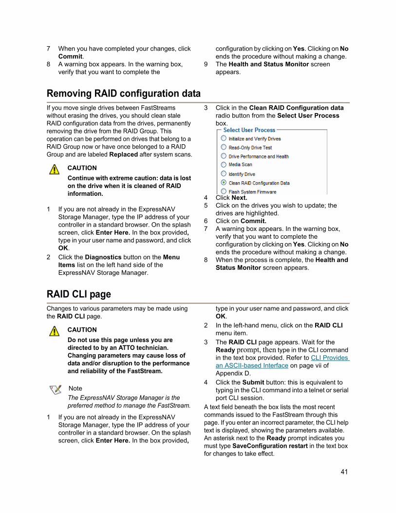
7 When you have completed your changes, click Commit.
8 A warning box appears. In the warning box, verify that you want to complete the
configuration by clicking on Yes. Clicking on No ends the procedure without making a change.
9 The Health and Status Monitor screen appears.
Removing RAID configuration dataIf you move single drives between FastStreams without erasing the drives, you should clean stale RAID configuration data from the drives, permanently removing the drive from the RAID Group. This operation can be performed on drives that belong to a RAID Group now or have once belonged to a RAID Group and are labeled Replaced after system scans.
CAUTIONCAUTION
Continue with extreme caution: data is lost on the drive when it is cleaned of RAID information.
1 If you are not already in the ExpressNAV Storage Manager, type the IP address of your controller in a standard browser. On the splash screen, click Enter Here. In the box provided, type in your user name and password, and click OK.
2 Click the Diagnostics button on the Menu Items list on the left hand side of the ExpressNAV Storage Manager.
3 Click in the Clean RAID Configuration data radio button from the Select User Process box.
4 Click Next.5 Click on the drives you wish to update; the
drives are highlighted.6 Click on Commit.7 A warning box appears. In the warning box,
verify that you want to complete the configuration by clicking on Yes. Clicking on No ends the procedure without making a change.
8 When the process is complete, the Health and Status Monitor screen appears.
RAID CLI pageChanges to various parameters may be made using the RAID CLI page.
CAUTIONCAUTION
Do not use this page unless you are directed to by an ATTO technician. Changing parameters may cause loss of data and/or disruption to the performance and reliability of the FastStream.
Note
The ExpressNAV Storage Manager is the preferred method to manage the FastStream.
1 If you are not already in the ExpressNAV Storage Manager, type the IP address of your controller in a standard browser. On the splash screen, click Enter Here. In the box provided,
type in your user name and password, and click OK.
2 In the left-hand menu, click on the RAID CLI menu item.
3 The RAID CLI page appears. Wait for the Ready prompt, then type in the CLI command in the text box provided. Refer to CLI Provides an ASCII-based Interface on page vii of Appendix D.
4 Click the Submit button: this is equivalent to typing in the CLI command into a telnet or serial port CLI session.
A text field beneath the box lists the most recent commands issued to the FastStream through this page. If you enter an incorrect parameter, the CLI help text is displayed, showing the parameters available. An asterisk next to the Ready prompt indicates you must type SaveConfiguration restart in the text box for changes to take effect.
41
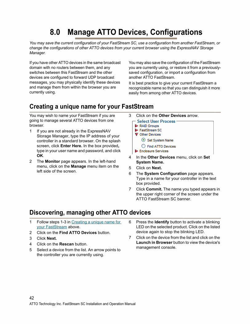
8.0 Manage ATTO Devices, ConfigurationsYou may save the current configuration of your FastStream SC, use a configuration from another FastStream, or change the configurations of other ATTO devices from your current browser using the ExpressNAV Storage Manager.
If you have other ATTO devices in the same broadcast domain with no routers between them, and any switches between this FastStream and the other devices are configured to forward UDP broadcast messages, you may physically identify these devices and manage them from within the browser you are currently using.
You may also save the configuration of the FastStream you are currently using, or restore it from a previously-saved configuration, or import a configuration from another ATTO FastStream.
It is best practice to give your current FastStream a recognizable name so that you can distinguish it more easily from among other ATTO devices.
Creating a unique name for your FastStream You may wish to name your FastStream if you are going to manage several ATTO devices from one browser.
1 If you are not already in the ExpressNAV Storage Manager, type the IP address of your controller in a standard browser. On the splash screen, click Enter Here. In the box provided, type in your user name and password, and click OK.
2 The Monitor page appears. In the left-hand menu, click on the Manage menu item on the left side of the screen.
3 Click on the Other Devices arrow.
4 In the Other Devices menu, click on Set System Name.
5 Click on Next.
6 The System Configuration page appears. Type in a name for your controller in the text box provided.
7 Click Commit. The name you typed appears in the upper right corner of the screen under the ATTO FastStream SC banner.
Discovering, managing other ATTO devices1 Follow steps 1-3 in Creating a unique name for
your FastStream above.
2 Click on the Find ATTO Devices button.
3 Click Next.
4 Click on the Rescan button.
5 Select a device from the list. An arrow points to the controller you are currently using.
6 Press the Identify button to activate a blinking LED on the selected product. Click on the listed device again to stop the blinking LED.
7 Click on the device from the list and click on the Launch in Browser button to view the device's management console.
42ATTO Technology Inc. FastStream SC Installation and Operation Manual
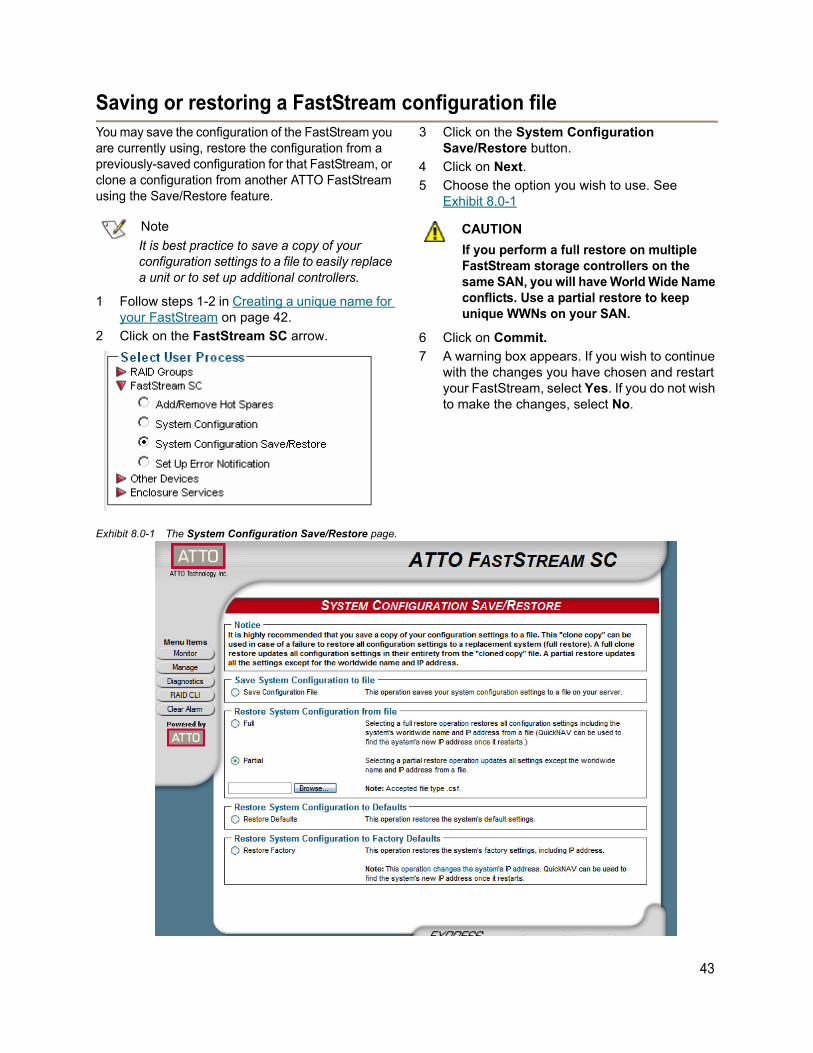
Saving or restoring a FastStream configuration fileYou may save the configuration of the FastStream you are currently using, restore the configuration from a previously-saved configuration for that FastStream, or clone a configuration from another ATTO FastStream using the Save/Restore feature.
Note
It is best practice to save a copy of your configuration settings to a file to easily replace a unit or to set up additional controllers.
1 Follow steps 1-2 in Creating a unique name for your FastStream on page 42.
2 Click on the FastStream SC arrow.
3 Click on the System Configuration Save/Restore button.
4 Click on Next.
5 Choose the option you wish to use. See Exhibit 8.0-1
CAUTIONCAUTION
If you perform a full restore on multiple FastStream storage controllers on the same SAN, you will have World Wide Name conflicts. Use a partial restore to keep unique WWNs on your SAN.
6 Click on Commit.
7 A warning box appears. If you wish to continue with the changes you have chosen and restart your FastStream, select Yes. If you do not wish to make the changes, select No.
Exhibit 8.0-1 The System Configuration Save/Restore page.
43
Field Replacement Unit (FRU)In the rare case that a FastStream must be replaced due to failure or upgrade, restoring a configuration file is a time saving tool to get storage back up and running quickly.
1 Disconnect cables and remove the original FastStream Storage Controller.
2 Connect the New FastStream by following steps 1-10 in Installing the FastStream on page 10.
3 Upload your saved configuration file following steps 1-7 in Saving or restoring a FastStream configuration file on page 43.
4 Restart your FastStream.
Once the FastStream comes online, you will have full access to all of the RAID Groups and data created with the previous FastStream.
Note
All user data, RAID Group information and metadata is stored on the disk drives. If a FastStream fails, all of the data remains intact and will be readily available once the FastStream is replaced.
44ATTO Technology Inc. FastStream SC Installation and Operation Manual

9.0 Interface OptionsThe best way to manage, monitor and configure the FastStream is to use the ExpressNAV Storage Manager, a browser-based application included with your FastStream, but you may use a terminal emulation program or Telnet.
Using the ExpressNAV Storage ManagerUse the ExpressNAV Storage Manager to manage, monitor and configure the unit. The choices you make lead you from screen to screen. Choices which are not available are greyed out.
Note
The FastStream is initially configured with DHCP enabled. It is best if you have access to a DHCP server.
1 Work from the computer attached to the FastStream Ethernet port. From the CD supplied with your FastStream, run the QuickNav Utility QuickNAV-windows.exe for Windows or QuickNAV-Mac for Mac OS X.
2 Locate the FastStream with the serial number recorded earlier.
3 Highlight the serial number.4 Click Next.
If a DHCP server is available on your network, an address is assigned automatically by the server. Note the assigned address: _____________________________________
If you do not have a DHCP server, get an IP address and subnet mask from your network administrator, type it into the area provided, and click on Next.
5 Click on Launch Browser.Your browser points to the ATTO ExpressNAV splash screen. Press Enter.
6 Type in the user name and password values.
Note
The default values are user name: root and password: Password. The user name is case insensitive and the password is case sensitive. It is best practice to change the user name and password. Refer to Changing current user name, password on page 26.
The pages which next appear depend on whether or not you have begun configuring the FastStream.
45
Using the serial portTo connect to a terminal emulation program to manage the FastStream, use the serial port.
1 Connect a cable from FastStream RS-232 serial port or header to the serial (COM) port on a personal computer.
2 Start a terminal emulation program on the personal computer, and use it to connect to the FastStream. For example, if you are using Hyper Terminal on a computer running a Windows operating system,
a. Type FastStream in the New Connection dialog box.
b. Click OK.
c. In the Connect To dialog box in the Connect using field, select the COM port number to which your serial cable is connected.
d. Click OK.
e. In the COM Properties dialog box select the following values:
• Bits per second: 115200 • Data Bits: 8• Parity: None • Stop Bits: 1 • Flow Control: None• Terminal type: ASCII• Echo: off
f. Click OK.
3 Turn on the FastStream.
4 After you connect to the FastStream, start-up messages are displayed. The last line in the start-up message sequence is Ready.
Make adjustments to the FastStream using the Command Line Interface as described in CLI Provides an ASCII-based Interface on page vii of Appendix D.
Note
In serial port sessions, there is no prompt on the line below the word Ready. Begin typing commands in the blank line where the cursor is resting. No user name or password is required for serial port access.
5 To verify that you have connected successfully, type help after the Ready prompt and press Enter.
If a list of all available commands does not appear on the screen, review the steps in this section, check the cable, or contact service personnel until the problem is solved.
If you have difficulty using the serial port, verify that you have the correct settings and that your serial cable is less then two meters in length.
Using TelnetUp to three Telnet sessions using the FastStream Ethernet management port can be conducted simultaneously. A serial port session can use the CLI while Telnet sessions are open. Whichever session issues the first set CLI command that requires a SaveConfiguration can continue to issue set commands, while the other sessions can only issue get commands or display information.
Once a connection is established, refer to CLI Provides an ASCII-based Interface on page vii of Appendix D.
1 Connect to the FastStream from a computer on the same Ethernet network.
2 Start a Telnet session.
Note
There is more than one way to connect to the FastStream using a telnet program.Your telnet program may operate differently than in the following instructions.
3 At the telnet prompt, issue the open command where x.x.x.x is the IP address of the FastStream.
telnet > open x.x.x.x
4 If you have to specify a port type, type in the port type “telnet” and the terminal type “SC100”.
port type: telnetterminal type: SC1005 Type in the default values for the user name,
root, and the password, Password, if you did not set new values in Changing current user name, password on page 26.
46ATTO Technology Inc. FastStream SC RAID Controller Installation and Operation Manual
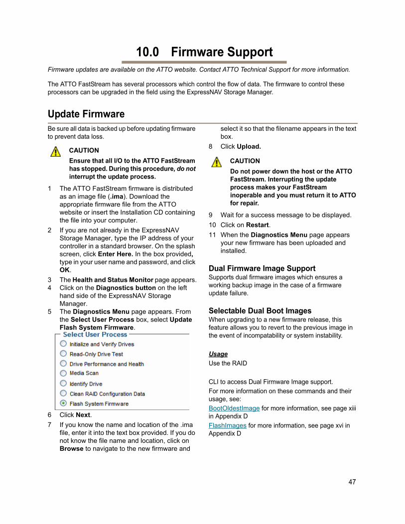
47
10.0 Firmware SupportFirmware updates are available on the ATTO website. Contact ATTO Technical Support for more information.
The ATTO FastStream has several processors which control the flow of data. The firmware to control these processors can be upgraded in the field using the ExpressNAV Storage Manager.
Update FirmwareBe sure all data is backed up before updating firmware to prevent data loss.
CAUTIONCAUTION
Ensure that all I/O to the ATTO FastStream has stopped. During this procedure, do not interrupt the update process.
1 The ATTO FastStream firmware is distributed as an image file (.ima). Download the appropriate firmware file from the ATTO website or insert the Installation CD containing the file into your computer.
2 If you are not already in the ExpressNAV Storage Manager, type the IP address of your controller in a standard browser. On the splash screen, click Enter Here. In the box provided, type in your user name and password, and click OK.
3 The Health and Status Monitor page appears.4 Click on the Diagnostics button on the left
hand side of the ExpressNAV Storage Manager.
5 The Diagnostics Menu page appears. From the Select User Process box, select Update Flash System Firmware.
6 Click Next.
7 If you know the name and location of the .ima file, enter it into the text box provided. If you do not know the file name and location, click on Browse to navigate to the new firmware and
select it so that the filename appears in the text box.
8 Click Upload.
CAUTIONCAUTION
Do not power down the host or the ATTO FastStream. Interrupting the update process makes your FastStream inoperable and you must return it to ATTO for repair.
9 Wait for a success message to be displayed.
10 Click on Restart.
11 When the Diagnostics Menu page appears your new firmware has been uploaded and installed.
Dual Firmware Image SupportSupports dual firmware images which ensures a working backup image in the case of a firmware update failure.
Selectable Dual Boot ImagesWhen upgrading to a new firmware release, this feature allows you to revert to the previous image in the event of incompatability or system instability.
Usage
Use the RAID
CLI to access Dual Firmware Image support.
For more information on these commands and their usage, see:
BootOldestImage for more information, see page xiii in Appendix D
FlashImages for more information, see page xvi in Appendix D
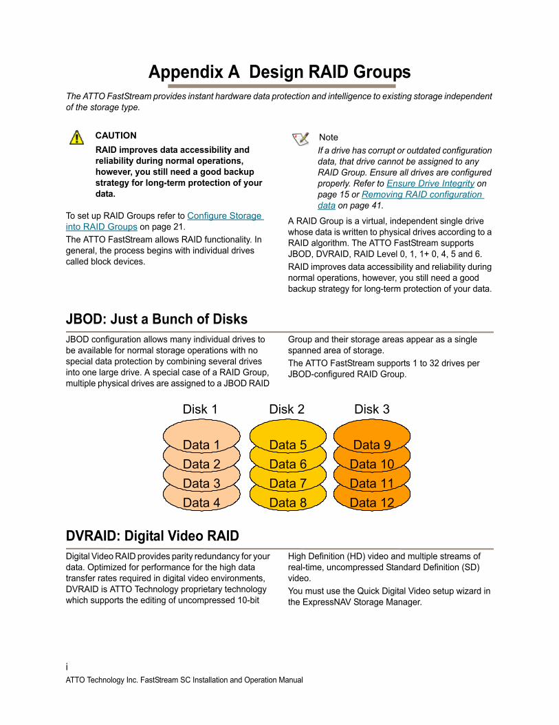
Appendix A Design RAID GroupsThe ATTO FastStream provides instant hardware data protection and intelligence to existing storage independent of the storage type.
CAUTIONCAUTION
RAID improves data accessibility and reliability during normal operations, however, you still need a good backup strategy for long-term protection of your data.
To set up RAID Groups refer to Configure Storage into RAID Groups on page 21.
The ATTO FastStream allows RAID functionality. In general, the process begins with individual drives called block devices.
Note
If a drive has corrupt or outdated configuration data, that drive cannot be assigned to any RAID Group. Ensure all drives are configured properly. Refer to Ensure Drive Integrity on page 15 or Removing RAID configuration data on page 41.
A RAID Group is a virtual, independent single drive whose data is written to physical drives according to a RAID algorithm. The ATTO FastStream supports JBOD, DVRAID, RAID Level 0, 1, 1+ 0, 4, 5 and 6.
RAID improves data accessibility and reliability during normal operations, however, you still need a good backup strategy for long-term protection of your data.
JBOD: Just a Bunch of DisksJBOD configuration allows many individual drives to be available for normal storage operations with no special data protection by combining several drives into one large drive. A special case of a RAID Group, multiple physical drives are assigned to a JBOD RAID
Group and their storage areas appear as a single spanned area of storage.
The ATTO FastStream supports 1 to 32 drives per JBOD-configured RAID Group.
DVRAID: Digital Video RAIDDigital Video RAID provides parity redundancy for your data. Optimized for performance for the high data transfer rates required in digital video environments, DVRAID is ATTO Technology proprietary technology which supports the editing of uncompressed 10-bit
High Definition (HD) video and multiple streams of real-time, uncompressed Standard Definition (SD) video.
You must use the Quick Digital Video setup wizard in the ExpressNAV Storage Manager.
Data 4
Data 3
Data 2
Data 1
Data 12
Data 11
Data 10
Data 9
Data 8
Data 7
Data 6
Data 5
Disk 1 Disk 2 Disk 3
iATTO Technology Inc. FastStream SC Installation and Operation Manual
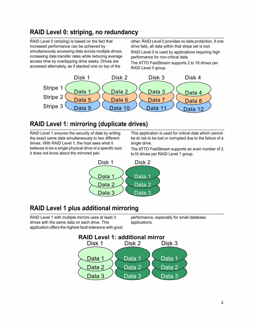
RAID Level 0: striping, no redundancyRAID Level 0 (striping) is based on the fact that increased performance can be achieved by simultaneously accessing data across multiple drives, increasing data transfer rates while reducing average access time by overlapping drive seeks. Drives are accessed alternately, as if stacked one on top of the
other. RAID Level 0 provides no data protection. If one drive fails, all data within that stripe set is lost.
RAID Level 0 is used by applications requiring high performance for non-critical data.
The ATTO FastStream supports 2 to 16 drives per RAID Level 0 group.
RAID Level 1: mirroring (duplicate drives)RAID Level 1 ensures the security of data by writing the exact same data simultaneously to two different drives. With RAID Level 1, the host sees what it believes to be a single physical drive of a specific size: it does not know about the mirrored pair.
This application is used for critical data which cannot be at risk to be lost or corrupted due to the failure of a single drive.
The ATTO FastStream supports an even number of 2 to16 drives per RAID Level 1 group.
RAID Level 1 plus additional mirroringRAID Level 1 with multiple mirrors uses at least 3 drives with the same data on each drive. This application offers the highest fault-tolerance with good
performance, especially for small database applications.
Stripe 2
Stripe 3 Data 12
Data 8
Data 4
Data 11
Data 7
Data 3
Data 10
Data 6
Data 2
Data 9
Data 5
Data 1Stripe 1
Disk 1 Disk 2 Disk 3 Disk 4
Data 3
Data 2
Data 1
Data 3
Data 2
Data 1
Disk 1 Disk 2
Data 3
Data 2
Data 1
Data 3
Data 2
Data 1
Data 3
Data 2
Data 1
Disk 1 Disk 2 Disk 3RAID Level 1: additional mirror
ii
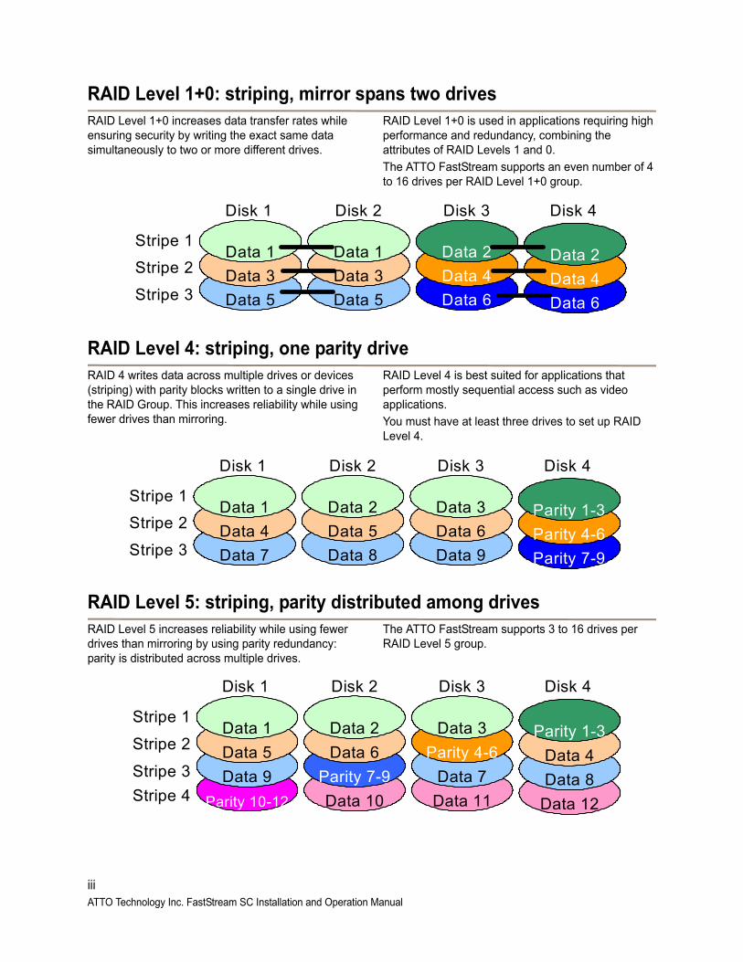
RAID Level 1+0: striping, mirror spans two drivesRAID Level 1+0 increases data transfer rates while ensuring security by writing the exact same data simultaneously to two or more different drives.
RAID Level 1+0 is used in applications requiring high performance and redundancy, combining the attributes of RAID Levels 1 and 0.
The ATTO FastStream supports an even number of 4 to 16 drives per RAID Level 1+0 group.
RAID Level 4: striping, one parity driveRAID 4 writes data across multiple drives or devices (striping) with parity blocks written to a single drive in the RAID Group. This increases reliability while using fewer drives than mirroring.
RAID Level 4 is best suited for applications that perform mostly sequential access such as video applications.
You must have at least three drives to set up RAID Level 4.
RAID Level 5: striping, parity distributed among drivesRAID Level 5 increases reliability while using fewer drives than mirroring by using parity redundancy: parity is distributed across multiple drives.
The ATTO FastStream supports 3 to 16 drives per RAID Level 5 group.
Stripe 1
Stripe 2
Stripe 3 Data 6
Data 4
Data 2
Data 6
Data 4
Data 2
Data 5
Data 3
Data 1
Data 5
Data 3
Data 1
Disk 1 Disk 2 Disk 3 Disk 4
Stripe 2
Stripe 3
Stripe 1
Parity 7-9
Parity 4-6
Parity 1-3
Data 9
Data 6
Data 3
Data 8
Data 5
Data 2
Data 7
Data 4
Data 1
Disk 1 Disk 2 Disk 3 Disk 4
Data 12Data 11Data 10Parity 10-12
Stripe 2
Stripe 3
Stripe 1
Data 8
Data 4
Parity 1-3
Data 7
Parity 4-6
Data 3
Parity 7-9
Data 6
Data 2
Data 9
Data 5
Data 1
Disk 1 Disk 2 Disk 3 Disk 4
Stripe 4
iiiATTO Technology Inc. FastStream SC Installation and Operation Manual
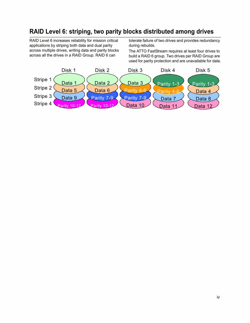
RAID Level 6: striping, two parity blocks distributed among drivesRAID Level 6 increases reliability for mission critical applications by striping both data and dual parity across multiple drives, writing data and parity blocks across all the drives in a RAID Group. RAID 6 can
tolerate failure of two drives and provides redundancy during rebuilds.
The ATTO FastStream requires at least four drives to build a RAID 6 group. Two drives per RAID Group are used for parity protection and are unavailable for data.
Data 11Data 10Parity 10-12Parity 10-12
Stripe 2
Stripe 3
Stripe 1
Data 7
Parity 4-6
Parity 1-3
Parity 7-9
Parity 4-6
Data 3
Parity 7-9
Data 6
Data 2
Data 9
Data 5
Data 1
Disk 1 Disk 2 Disk 3 Disk 4
Stripe 4 Data 12
Data 8
Data 4
Parity 1-3
Disk 5
iv

vATTO Technology Inc. FastStream SC Installation and Operation Manual
Appendix B MultipathingTo optimize storage availability and performance, it is recommended that you take advantage of failover and load balancing provided by host based multipathing.
The FastStream Storage Controller is compatible with generic multipathing for Windows, Mac OS X and Linux but is optimized for use with ATTO’s MultiPath DirectorTM for Mac OS X, Linux and Windows.
Improved Availability of Storage with improved performanceMultipathing Failover: Redundant physical path components - host adapters, SFPs, cables and switches are used to create logical “paths” between the server and the storage device. In the event that one or more of these components fails, causing the path to fail, ATTO Multipathing logic uses an alternate path for I/O so that applications can still access their data.
Multipathing Load-Balancing: Multipathing software also serves to redistribute the read/write load among multiple paths between the server and storage, thereby helping to remove bottlenecks and to balance workloads for better overall performance.
Load Balancing algorithms provided by ATTO MultiPath Director for OS X and a DSM MPIO Driver for Windows ServerPressure: The path with the fewest number of bytes being transferred is selected for I/O. Pressure load balancing is domain based. The first level of path selection is based on the domain (adapter channel) with the fewest number of bytes being transferred. If there are multiple paths to a target on a domain, a second level of selection is used. Pressure load balancing provides the best (or equal) performance of all load balancing policies regardless of storage topology.
Queue Depth: The path with the fewest outstanding I/O transactions is selected for I/O. This target-based policy is not generally recommended for use in an environment with mixed I/O transfers to many devices.
Round Robin: Data is distributed down all paths equally; the least-used path is selected for I/O. Like Queue Depth, this target-based policy uses an I/O count for path selection; however the count is cumulative for all I/O in the current configuration (not the number of currently queued I/O’s). If an application issues an I/O down one path to a dual ported device, then issues another one five minutes later, the other path will be used.
Setup of the FastStream with MultipathingSetup instructions for ATTO Celerity MultiPath DirectorTM for OS X, Windows, Red Hat and SUSE Linux multipathing can be found on the product CD. If you need to purchase an ATTO Celerity FC Host Adapter you may buy direct at www.attostore.com or contact ATTO Sales at 716-691-1999 x240.
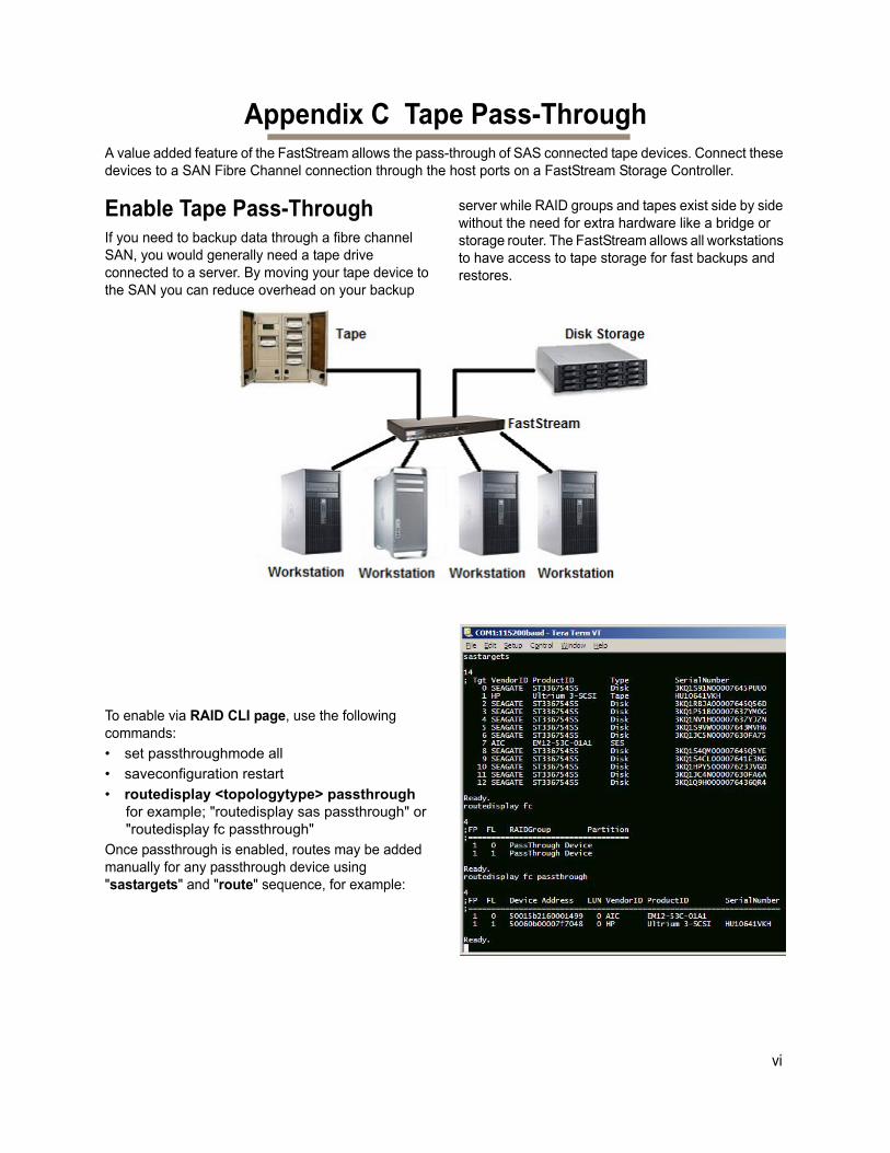
vi
Appendix C Tape Pass-ThroughA value added feature of the FastStream allows the pass-through of SAS connected tape devices. Connect these devices to a SAN Fibre Channel connection through the host ports on a FastStream Storage Controller.
Enable Tape Pass-ThroughIf you need to backup data through a fibre channel SAN, you would generally need a tape drive connected to a server. By moving your tape device to the SAN you can reduce overhead on your backup
server while RAID groups and tapes exist side by side without the need for extra hardware like a bridge or storage router. The FastStream allows all workstations to have access to tape storage for fast backups and restores.
To enable via RAID CLI page, use the following commands:
• set passthroughmode all
• saveconfiguration restart
• routedisplay <topologytype> passthrough for example; "routedisplay sas passthrough" or "routedisplay fc passthrough"
Once passthrough is enabled, routes may be added manually for any passthrough device using "sastargets" and "route" sequence, for example:
Appendix D CLI Provides an ASCII-based InterfaceThe command line interface (CLI) uses ASCII commands typed while in CLI mode.
CAUTIONCAUTION
Do not use CLI unless you are directed to by an ATTO technician.
Changing parameters may cause loss of data and/or disruption to performance and reliability of the FastStream.
The ExpressNAV Storage Manager is the preferred method to operate and manage the FastStream. Refer to Using the ExpressNAV Storage Manager on page 43 for details.
The command line interface (CLI) is a set of ASCII-based commands which perform configuration and diagnostic tasks.You may use them through the ExpressNAV Storage Manager Advanced CLI page (refer to RAID CLI page on page 39) or by using the serial port interface or the Ethernet management port (refer to Interface Options on page 43).
• CLI commands are context sensitive and generally follow a standard format
[Get|Set] Command [Parameter1|Parameter2]
followed by the return or enter key.
• CLI commands are case insensitive: you may type all upper or all lower case or a mixture. Upper and lower case in this manual and the help screen are for clarification only.
• Commands generally have three types of operation: get, set and immediate.
• The get form returns the value of a parameter or setting and is an informational command.
• Responses to get commands are followed by Ready.
• The set form is an action that changes the value of a parameter or configuration setting. It may require a SaveConfiguration command and a restart of the system before it is implemented. The restart can be accomplished as part of the SaveConfiguration command or by using a separate FirmwareRestart command. A number of set commands may be issued before the SaveConfiguration command.
• Responses to set commands are either an error message or Ready. *. The asterisk indicates you must use a SaveConfiguration command to finalize the set command.
• Set commands which do not require a SaveConfiguration command are immediately executed.
Note
Using certain CLI commands during normal operation can cause a performance drop. Once command actions are complete, performance should return to normal levels.
Exhibit A-1 Symbols, typefaces and abbreviations used to indicate functions and elements of the command line interface used in this manual.
Symbol/Abbreviation Indicates
- A range (6 – 9 = 6, 7, 8, 9)
... Indicates optional repetition of the preceding item
[ ] Required entry
| Pick one of
< > Optional entry
BlockDevID Index designation of a block as found by using the BlockDevScan command
EnclosureIndex Index designation of an enclosure found by using the SESIdentify command
fl Fibre Channel LUN ID (0 <= fl <= 31)
fp Fibre Channel port number (1 <= fp <= 2)
vii
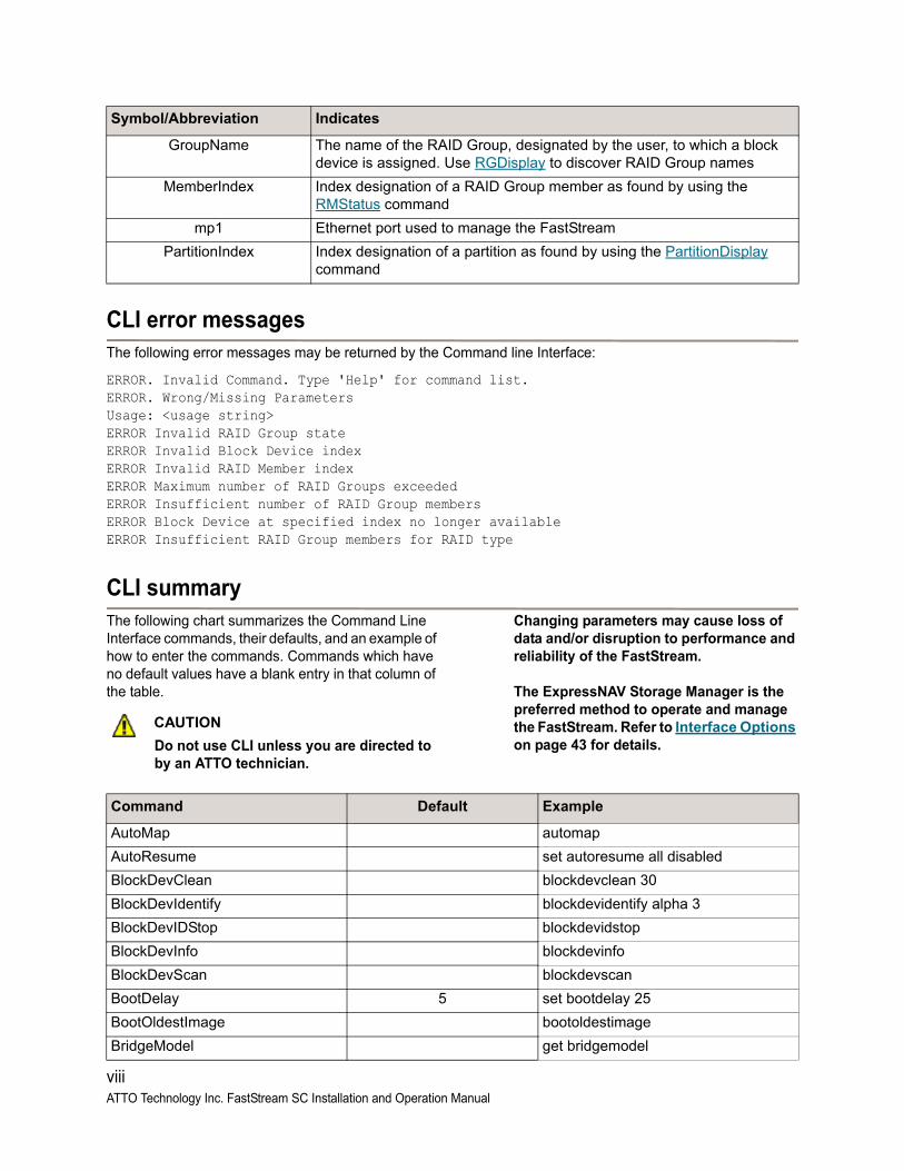
CLI error messagesThe following error messages may be returned by the Command line Interface:
ERROR. Invalid Command. Type 'Help' for command list. ERROR. Wrong/Missing Parameters Usage: <usage string>ERROR Invalid RAID Group stateERROR Invalid Block Device indexERROR Invalid RAID Member indexERROR Maximum number of RAID Groups exceededERROR Insufficient number of RAID Group membersERROR Block Device at specified index no longer availableERROR Insufficient RAID Group members for RAID type
CLI summary The following chart summarizes the Command Line Interface commands, their defaults, and an example of how to enter the commands. Commands which have no default values have a blank entry in that column of the table.
CAUTIONCAUTION
Do not use CLI unless you are directed to by an ATTO technician.
Changing parameters may cause loss of data and/or disruption to performance and reliability of the FastStream.
The ExpressNAV Storage Manager is the preferred method to operate and manage the FastStream. Refer to Interface Options on page 43 for details.
GroupName The name of the RAID Group, designated by the user, to which a block device is assigned. Use RGDisplay to discover RAID Group names
MemberIndex Index designation of a RAID Group member as found by using the RMStatus command
mp1 Ethernet port used to manage the FastStream
PartitionIndex Index designation of a partition as found by using the PartitionDisplay command
Symbol/Abbreviation Indicates
Command Default Example
AutoMap automap
AutoResume set autoresume all disabled
BlockDevClean blockdevclean 30
BlockDevIdentify blockdevidentify alpha 3
BlockDevIDStop blockdevidstop
BlockDevInfo blockdevinfo
BlockDevScan blockdevscan
BootDelay 5 set bootdelay 25
BootOldestImage bootoldestimage
BridgeModel get bridgemodel
viii ATTO Technology Inc. FastStream SC Installation and Operation Manual
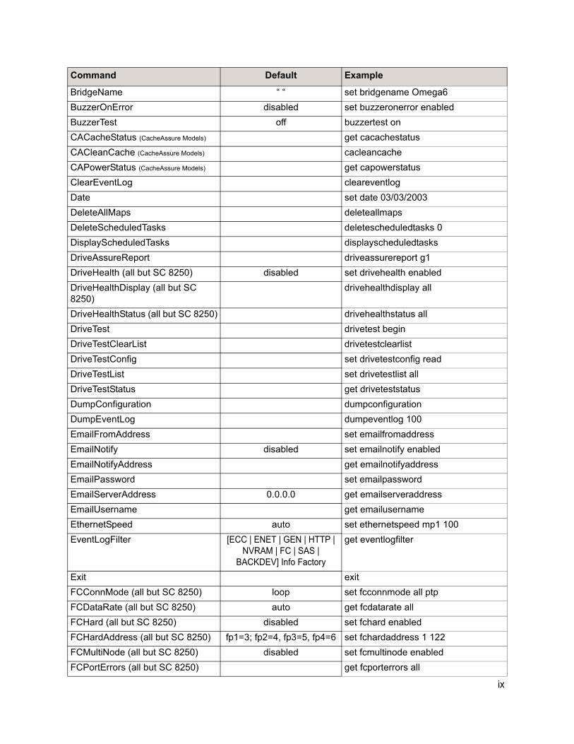
BridgeName “ “ set bridgename Omega6
BuzzerOnError disabled set buzzeronerror enabled
BuzzerTest off buzzertest on
CACacheStatus (CacheAssure Models) get cacachestatus
CACleanCache (CacheAssure Models) cacleancache
CAPowerStatus (CacheAssure Models) get capowerstatus
ClearEventLog cleareventlog
Date set date 03/03/2003
DeleteAllMaps deleteallmaps
DeleteScheduledTasks deletescheduledtasks 0
DisplayScheduledTasks displayscheduledtasks
DriveAssureReport driveassurereport g1
DriveHealth (all but SC 8250) disabled set drivehealth enabled
DriveHealthDisplay (all but SC 8250)
drivehealthdisplay all
DriveHealthStatus (all but SC 8250) drivehealthstatus all
DriveTest drivetest begin
DriveTestClearList drivetestclearlist
DriveTestConfig set drivetestconfig read
DriveTestList set drivetestlist all
DriveTestStatus get driveteststatus
DumpConfiguration dumpconfiguration
DumpEventLog dumpeventlog 100
EmailFromAddress set emailfromaddress
EmailNotify disabled set emailnotify enabled
EmailNotifyAddress get emailnotifyaddress
EmailPassword set emailpassword
EmailServerAddress 0.0.0.0 get emailserveraddress
EmailUsername get emailusername
EthernetSpeed auto set ethernetspeed mp1 100
EventLogFilter [ECC | ENET | GEN | HTTP | NVRAM | FC | SAS |
BACKDEV] Info Factory
get eventlogfilter
Exit exit
FCConnMode (all but SC 8250) loop set fcconnmode all ptp
FCDataRate (all but SC 8250) auto get fcdatarate all
FCHard (all but SC 8250) disabled set fchard enabled
FCHardAddress (all but SC 8250) fp1=3; fp2=4, fp3=5, fp4=6 set fchardaddress 1 122
FCMultiNode (all but SC 8250) disabled set fcmultinode enabled
FCPortErrors (all but SC 8250) get fcporterrors all
Command Default Example
ix
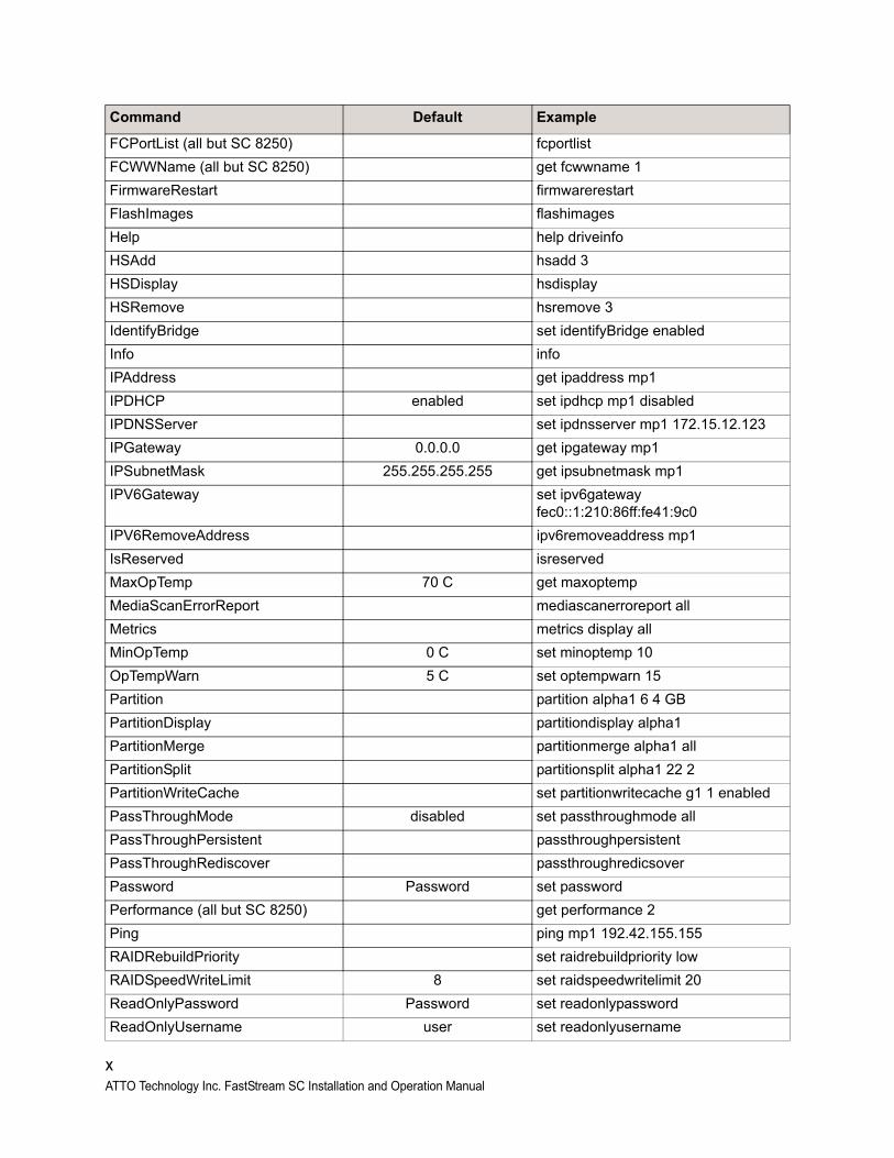
FCPortList (all but SC 8250) fcportlist
FCWWName (all but SC 8250) get fcwwname 1
FirmwareRestart firmwarerestart
FlashImages flashimages
Help help driveinfo
HSAdd hsadd 3
HSDisplay hsdisplay
HSRemove hsremove 3
IdentifyBridge set identifyBridge enabled
Info info
IPAddress get ipaddress mp1
IPDHCP enabled set ipdhcp mp1 disabled
IPDNSServer set ipdnsserver mp1 172.15.12.123
IPGateway 0.0.0.0 get ipgateway mp1
IPSubnetMask 255.255.255.255 get ipsubnetmask mp1
IPV6Gateway set ipv6gateway fec0::1:210:86ff:fe41:9c0
IPV6RemoveAddress ipv6removeaddress mp1
IsReserved isreserved
MaxOpTemp 70 C get maxoptemp
MediaScanErrorReport mediascanerroreport all
Metrics metrics display all
MinOpTemp 0 C set minoptemp 10
OpTempWarn 5 C set optempwarn 15
Partition partition alpha1 6 4 GB
PartitionDisplay partitiondisplay alpha1
PartitionMerge partitionmerge alpha1 all
PartitionSplit partitionsplit alpha1 22 2
PartitionWriteCache set partitionwritecache g1 1 enabled
PassThroughMode disabled set passthroughmode all
PassThroughPersistent passthroughpersistent
PassThroughRediscover passthroughredicsover
Password Password set password
Performance (all but SC 8250) get performance 2
Ping ping mp1 192.42.155.155
RAIDRebuildPriority set raidrebuildpriority low
RAIDSpeedWriteLimit 8 set raidspeedwritelimit 20
ReadOnlyPassword Password set readonlypassword
ReadOnlyUsername user set readonlyusername
Command Default Example
x ATTO Technology Inc. FastStream SC Installation and Operation Manual
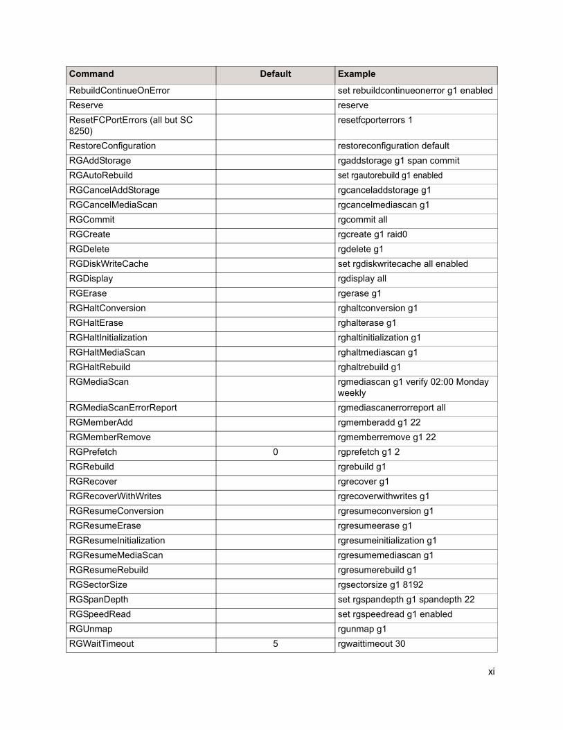
RebuildContinueOnError set rebuildcontinueonerror g1 enabled
Reserve reserve
ResetFCPortErrors (all but SC 8250)
resetfcporterrors 1
RestoreConfiguration restoreconfiguration default
RGAddStorage rgaddstorage g1 span commit
RGAutoRebuild set rgautorebuild g1 enabled
RGCancelAddStorage rgcanceladdstorage g1
RGCancelMediaScan rgcancelmediascan g1
RGCommit rgcommit all
RGCreate rgcreate g1 raid0
RGDelete rgdelete g1
RGDiskWriteCache set rgdiskwritecache all enabled
RGDisplay rgdisplay all
RGErase rgerase g1
RGHaltConversion rghaltconversion g1
RGHaltErase rghalterase g1
RGHaltInitialization rghaltinitialization g1
RGHaltMediaScan rghaltmediascan g1
RGHaltRebuild rghaltrebuild g1
RGMediaScan rgmediascan g1 verify 02:00 Monday weekly
RGMediaScanErrorReport rgmediascanerrorreport all
RGMemberAdd rgmemberadd g1 22
RGMemberRemove rgmemberremove g1 22
RGPrefetch 0 rgprefetch g1 2
RGRebuild rgrebuild g1
RGRecover rgrecover g1
RGRecoverWithWrites rgrecoverwithwrites g1
RGResumeConversion rgresumeconversion g1
RGResumeErase rgresumeerase g1
RGResumeInitialization rgresumeinitialization g1
RGResumeMediaScan rgresumemediascan g1
RGResumeRebuild rgresumerebuild g1
RGSectorSize rgsectorsize g1 8192
RGSpanDepth set rgspandepth g1 spandepth 22
RGSpeedRead set rgspeedread g1 enabled
RGUnmap rgunmap g1
RGWaitTimeout 5 rgwaittimeout 30
Command Default Example
xi
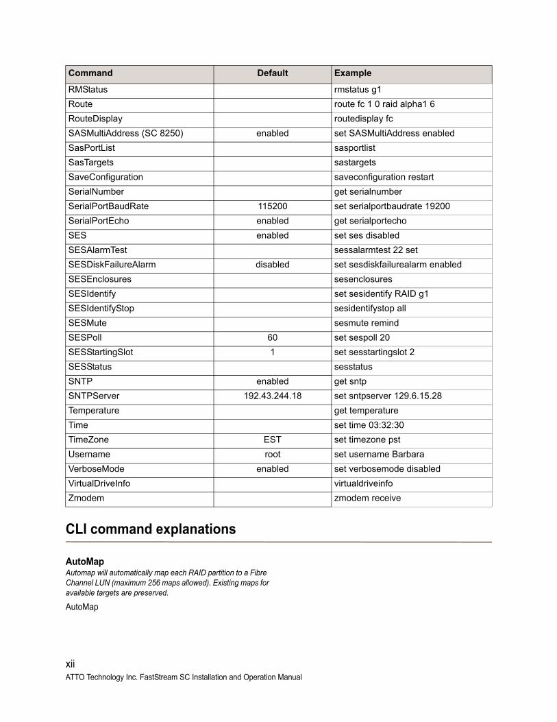
CLI command explanations
AutoMapAutomap will automatically map each RAID partition to a Fibre Channel LUN (maximum 256 maps allowed). Existing maps for available targets are preserved.
AutoMap
RMStatus rmstatus g1
Route route fc 1 0 raid alpha1 6
RouteDisplay routedisplay fc
SASMultiAddress (SC 8250) enabled set SASMultiAddress enabled
SasPortList sasportlist
SasTargets sastargets
SaveConfiguration saveconfiguration restart
SerialNumber get serialnumber
SerialPortBaudRate 115200 set serialportbaudrate 19200
SerialPortEcho enabled get serialportecho
SES enabled set ses disabled
SESAlarmTest sessalarmtest 22 set
SESDiskFailureAlarm disabled set sesdiskfailurealarm enabled
SESEnclosures sesenclosures
SESIdentify set sesidentify RAID g1
SESIdentifyStop sesidentifystop all
SESMute sesmute remind
SESPoll 60 set sespoll 20
SESStartingSlot 1 set sesstartingslot 2
SESStatus sesstatus
SNTP enabled get sntp
SNTPServer 192.43.244.18 set sntpserver 129.6.15.28
Temperature get temperature
Time set time 03:32:30
TimeZone EST set timezone pst
Username root set username Barbara
VerboseMode enabled set verbosemode disabled
VirtualDriveInfo virtualdriveinfo
Zmodem zmodem receive
Command Default Example
xii ATTO Technology Inc. FastStream SC Installation and Operation Manual
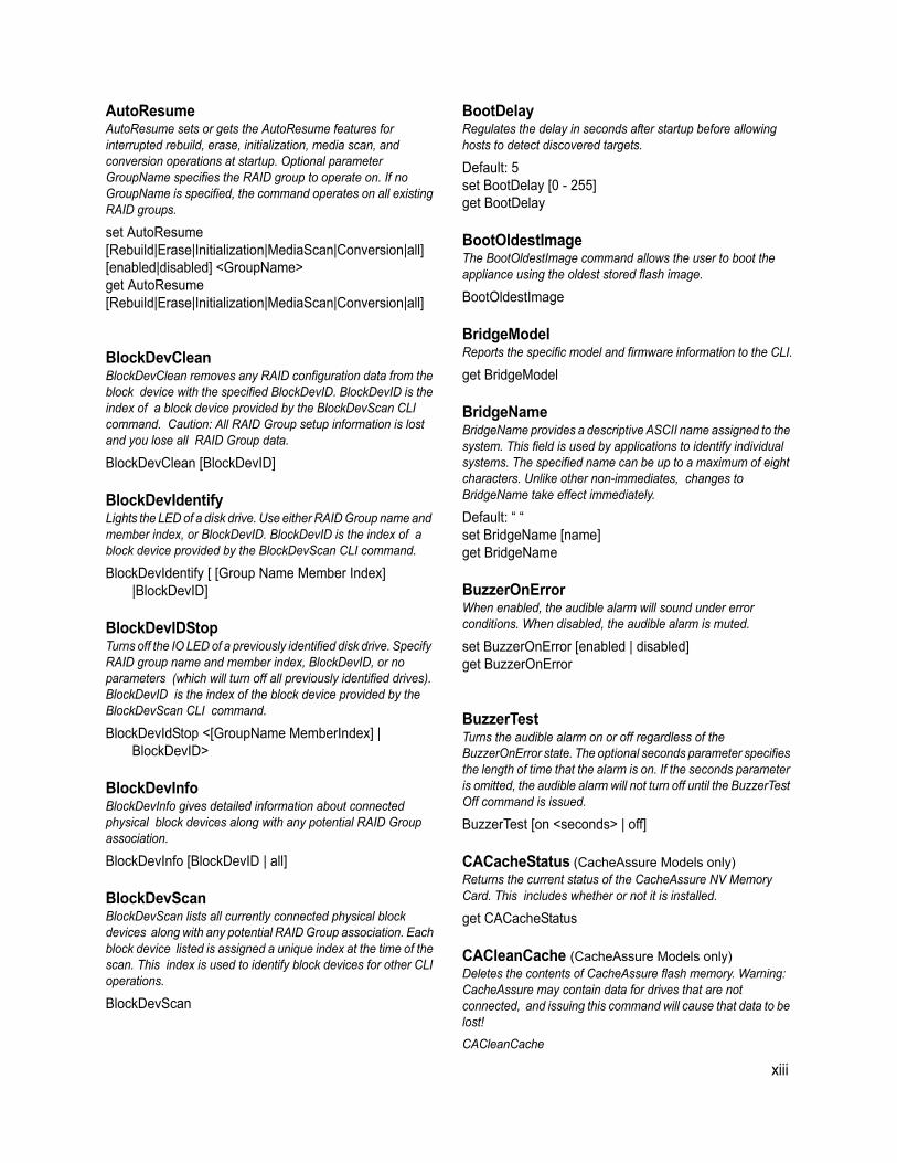
AutoResumeAutoResume sets or gets the AutoResume features for interrupted rebuild, erase, initialization, media scan, and conversion operations at startup. Optional parameter GroupName specifies the RAID group to operate on. If no GroupName is specified, the command operates on all existing RAID groups.
set AutoResume[Rebuild|Erase|Initialization|MediaScan|Conversion|all][enabled|disabled] <GroupName>get AutoResume[Rebuild|Erase|Initialization|MediaScan|Conversion|all]
BlockDevCleanBlockDevClean removes any RAID configuration data from the block device with the specified BlockDevID. BlockDevID is the index of a block device provided by the BlockDevScan CLI command. Caution: All RAID Group setup information is lost and you lose all RAID Group data.
BlockDevClean [BlockDevID]
BlockDevIdentifyLights the LED of a disk drive. Use either RAID Group name and member index, or BlockDevID. BlockDevID is the index of a block device provided by the BlockDevScan CLI command.
BlockDevIdentify [ [Group Name Member Index] |BlockDevID]
BlockDevIDStopTurns off the IO LED of a previously identified disk drive. Specify RAID group name and member index, BlockDevID, or no parameters (which will turn off all previously identified drives). BlockDevID is the index of the block device provided by the BlockDevScan CLI command.
BlockDevIdStop <[GroupName MemberIndex] | BlockDevID>
BlockDevInfoBlockDevInfo gives detailed information about connected physical block devices along with any potential RAID Group association.
BlockDevInfo [BlockDevID | all]
BlockDevScanBlockDevScan lists all currently connected physical block devices along with any potential RAID Group association. Each block device listed is assigned a unique index at the time of the scan. This index is used to identify block devices for other CLI operations.
BlockDevScan
BootDelay Regulates the delay in seconds after startup before allowing hosts to detect discovered targets.
Default: 5set BootDelay [0 - 255]get BootDelay
BootOldestImageThe BootOldestImage command allows the user to boot the appliance using the oldest stored flash image.
BootOldestImage
BridgeModelReports the specific model and firmware information to the CLI.
get BridgeModel
BridgeNameBridgeName provides a descriptive ASCII name assigned to the system. This field is used by applications to identify individual systems. The specified name can be up to a maximum of eight characters. Unlike other non-immediates, changes to BridgeName take effect immediately.
Default: “ “set BridgeName [name]get BridgeName
BuzzerOnErrorWhen enabled, the audible alarm will sound under error conditions. When disabled, the audible alarm is muted.
set BuzzerOnError [enabled | disabled]get BuzzerOnError
BuzzerTestTurns the audible alarm on or off regardless of the BuzzerOnError state. The optional seconds parameter specifies the length of time that the alarm is on. If the seconds parameter is omitted, the audible alarm will not turn off until the BuzzerTest Off command is issued.
BuzzerTest [on <seconds> | off]
CACacheStatus (CacheAssure Models only)Returns the current status of the CacheAssure NV Memory Card. This includes whether or not it is installed.
get CACacheStatus
CACleanCache (CacheAssure Models only)Deletes the contents of CacheAssure flash memory. Warning: CacheAssure may contain data for drives that are not connected, and issuing this command will cause that data to be lost!
CACleanCache
xiii
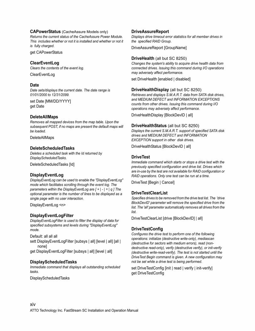
CAPowerStatus (CacheAssure Models only)Returns the current status of the CacheAssure Power Module. This includes whether or not it is installed and whether or not it is fully charged.
get CAPowerStatus
ClearEventLogClears the contents of the event log.
ClearEventLog
DateDate sets/displays the current date. The date range is 01/01/2000 to 12/31/2099.
set Date [MM/DD/YYYY]get Date
DeleteAllMapsRemoves all mapped devices from the map table. Upon the subsequent POST, if no maps are present the default maps will be loaded.
DeleteAllMaps
DeleteScheduledTasksDeletes a scheduled task with the Id returned by DisplayScheduledTasks.
DeleteScheduledTasks [Id]
DisplayEventLogDisplayEventLog can be used to enable the "DisplayEventLog" mode which facilitates scrolling through the event log. The parameters within the DisplayEventLog are [ + | - | = | q ] The optional parameter is the number of lines to be displayed as a single page with no user interaction.
DisplayEventLog <n>
DisplayEventLogFilterDisplayEventLogFilter is used to filter the display of data for specified subsystems and levels during "DisplayEventLog" mode.
Default: all all allsett DisplayEventLogFilter [subsys | all] [level | all] [all |
none]get DisplayEventLogFilter [subsys | all] [level | all]
DisplayScheduledTasksImmediate command that displays all outstanding scheduled tasks.
DisplayScheduledTasks
DriveAssureReportDisplays drive timeout error statistics for all member drives in the specified RAID Group.
DriveAssureReport [GroupName]
DriveHealth (all but SC 8250)Changes the system's ability to acquire drive health data from connected drives. Issuing this command during I/O operations may adversely affect performance.
set DriveHealth [enabled | disabled]
DriveHealthDisplay (all but SC 8250)Retrieves and displays S.M.A.R.T. data from SATA disk drives, and MEDIUM DEFECT and INFORMATION EXCEPTIONS counts from other drives. Issuing this command during I/O operations may adversely affect performance.
DriveHealthDisplay [BlockDevID | all]
DriveHealthStatus (all but SC 8250)Displays the current S.M.A.R.T. support of specified SATA disk drives and MEDIUM DEFECT and INFORMATION EXCEPTION support in other disk drives.
DriveHealthStatus [BlockDevID | all]
DriveTestImmediate command which starts or stops a drive test with the previously specified configuration and drive list. Drives which are in-use by the test are not available for RAID configuration or RAID operations. Only one test can be run at a time.
DriveTest [Begin | Cancel]
DriveTestClearListSpecifies drives to be removed from the drive test list. The 'drive BlockDevID' parameter will remove the specified drive from the list. The 'all' parameter automatically removes all drives from the list.
DriveTestClearList [drive [BlockDevID] | all]
DriveTestConfigConfigures the drive test to perform one of the following operations: initialize (destructive write-only), mediascan (destructive for sectors with medium errors), read (non-destructive read-only), verify (destructive verify), or init-verify (destructive write-read-verify). The test is not started until the DriveTest Begin command is given. A new configuration may not be set while a drive test is being performed.
set DriveTestConfig [init | read | verify | init-verify]get DriveTestConfig
xiv ATTO Technology Inc. FastStream SC Installation and Operation Manual
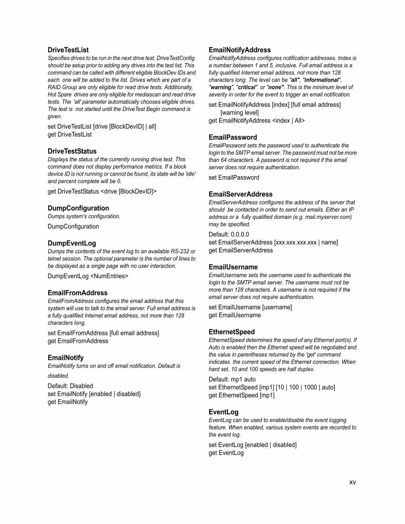
DriveTestList Specifies drives to be run in the next drive test. DriveTestConfig should be setup prior to adding any drives into the test list. This command can be called with different eligible BlockDev IDs and each one will be added to the list. Drives which are part of a RAID Group are only eligible for read drive tests. Additionally, Hot Spare drives are only eligible for mediascan and read drive tests. The 'all' parameter automatically chooses eligible drives. The test is not started until the DriveTest Begin command is given.
set DriveTestList [drive [BlockDevID] | all]get DriveTestList
DriveTestStatus Displays the status of the currently running drive test. This command does not display performance metrics. If a block device ID is not running or cannot be found, its state will be 'idle' and percent complete will be 0.
get DriveTestStatus <drive [BlockDevID]>
DumpConfigurationDumps system's configuration.
DumpConfiguration
DumpEventLogDumps the contents of the event log to an available RS-232 or telnet session. The optional parameter is the number of lines to be displayed as a single page with no user interaction.
DumpEventLog <NumEntries>
EmailFromAddressEmailFromAddress configures the email address that this system will use to talk to the email server. Full email address is a fully qualified Internet email address, not more than 128 characters long.
set EmailFromAddress [full email address]get EmailFromAddress
EmailNotifyEmailNotify turns on and off email notification. Default is
disabled.
Default: Disabledset EmailNotify [enabled | disabled]get EmailNotify
EmailNotifyAddressEmailNotifyAddress configures notification addresses. Index is a number between 1 and 5, inclusive. Full email address is a fully qualified Internet email address, not more than 128 characters long. The level can be "all", "informational", "warning", "critical" or "none". This is the minimum level of severity in order for the event to trigger an email notification.
set EmailNotifyAddress [index] [full email address] [warning level]
get EmailNotifyAddress <index | All>
EmailPasswordEmailPassword sets the password used to authenticate the login to the SMTP email server. The password must not be more than 64 characters. A password is not required if the email server does not require authentication.
set EmailPassword
EmailServerAddressEmailServerAddress configures the address of the server that should be contacted in order to send out emails. Either an IP address or a fully qualified domain (e.g. mail.myserver.com) may be specified.
Default: 0.0.0.0set EmailServerAddress [xxx.xxx.xxx.xxx | name]get EmailServerAddress
EmailUsername EmailUsername sets the username used to authenticate the login to the SMTP email server. The username must not be more than 128 characters. A username is not required if the email server does not require authentication.
set EmailUsername [username]get EmailUsername
EthernetSpeed EthernetSpeed determines the speed of any Ethernet port(s). If Auto is enabled then the Ethernet speed will be negotiated and the value in parentheses returned by the 'get' command indicates the current speed of the Ethernet connection. When hard set, 10 and 100 speeds are half duplex.
Default: mp1 autoset EthernetSpeed [mp1] [10 | 100 | 1000 | auto]get EthernetSpeed [mp1]
EventLogEventLog can be used to enable/disable the event logging feature. When enabled, various system events are recorded to the event log.
set EventLog [enabled | disabled]get EventLog
xv
EventLogFilterSpecifies what events to include in the event log display. Type "get EventLogFilter" for a list of valid subsystems. Specify a subsystem with "none" to disable event display for that subsystem. Levels are "info", "warn" and "crit". Specify "info" to display all levels, "warn" to display warnings and critical events, "crit" to display only critical events. Events are classified "factory" or "user" (factory events provide detailed information for factory debug, and they are marked with a dash.) Specify "factory" to display all events, or specify "user" to display only user events.
Default: [ECC | ENET | GEN | HTTP | NVRAM | FC | SAS | BACKDEV] Info Factory
set EventLogFilter [subsys | all] [[info | warn | crit] [factory | user]] | none]
get EventLogFilter
Exit Exit terminates the current CLI session over Telnet. This command has no effect if used during a serial RS-232 session.
Exit
FCConnMode (all but SC 8250)FCConnMode specifies the connection mode used when communicating across a Fibre Channel network. The system will connect to an arbitrated loop (FC_AL) if 'loop' is selected. The system will connect in point-to-point mode if 'ptp' is selected. The options of 'loop-ptp' (AL Preferred) and 'ptp-loop' (PTP Preferred) allow auto-negotiation while indicating a preference.
Default: loopset FCConnMode [fp | all] [loop | ptp | loop-ptp | ptp-loop]get FCConnMode [fp | all]
FCDataRate (all but SC 8250)FCDataRate specifies the Fibre Channel data rate at which operation will occur. Choices are 2Gb/s, 4Gb/s, 8Gb/s or Auto-negotiated. Note - the FCDataRate displayed in the "info" output will toggle between 1Gb (5550 only), 2Gb, 4Gb, and 8Gb (8550 only) on 8Gbit-capable hardware if no connection has been established.
set FCDataRate [fp | all] [2Gb | 4Gb | 8Gb | auto]get FCDataRate [fp | all]
FCHard (all but SC 8250)FCHard enables and disables Fibre Channel hard address assignment. When FCHard is enabled, the internal hard address will be used as the loop address on the Fibre Channel loop. Under soft addressing, the loop address is assigned during loop initialization.
set FCHard [enabled | disabled]get FCHard
FCHardAddress (all but SC 8250)FCHardAddress specifies the value used as the FC-AL hard address. This value represents the address that will be used if hard addressing is enabled. The range of valid Fibre Channel Hard Address values is 0 through 125.
set FCHardAddress [fp | all] [address]get FCHardAddress [fp | all]
FCMultiNode (all but SC 8250)FCMultiNode determines the reported identity of Fibre Channel ports. When enabled, each port reports a separate unique Node Name and logical units may be mapped to either port. When disabled, each port reports the same Node Name and each logical unit mapping is applied to all ports.
set FCMultiNode [enabled | disabled]get FCMultiNode
FCPortErrors (all but SC 8250)FCPortErrors displays the number of Fibre Channel errors that have occurred since the last reboot/power-on or ResetFcPortErrors.
get FCPortErrors [fp | all]
FCPortList (all but SC 8250)FCPortList displays a list of available Fibre Channel ports and their current status. Valid status values are: Up, Down, Failed, Reserved, and Disabled.
FCPortList
FCWWName (all but SC 8250)FCWWName reports the World Wide Node Name of the Fibre Channel interface referenced. Each Fibre Channel port has an individual and unique 8-byte Node Name if the FCMultiNode setting is enabled.
get FCWWName [fp | all]
FirmwareRestartFirmwareRestart resets and reinitializes the firmware. Use the 'forced' option to override any CLI reservations held by other sessions.
FirmwareRestart <forced>
FlashImagesFlashImages displays the metadata for software images currently stored in the Flash device. The optional parameter "validate" also validates the CRC of the flash images. Note that the CRC validation causes a multi-second delay.
FlashImages <validate>
xvi ATTO Technology Inc. FastStream SC Installation and Operation Manual
HelpThe Help command issued with no parameters displays a list of available CLI commands. When a CLI Command name is specified, a command usage string and command description is presented on the CLI.
Help <command>
HSAddHSAdd assigns a Block Device to the Hot Spare pool. Optional parameter "RAID" and RAID Group name is the ASCII name of the RAID Group for which to reserve a Dedicated Hot Spare; this means the Hot Spare is assigned solely to the specified RAID Group. If no Group name is specified, the Hot Spare is a global Hot Spare and available for use by any RAID Group.
HSAdd <RAID GrpName> [BlockDevID]
HSDisplayHSDisplay outputs a list of all of the devices in the Hot Spare pool.
HSDisplay
HSRemoveRemoves a Block Device from the Hot Spare pool.
HSRemove [BlockDevID | all]
IdentifyBridge IdentifyBridge causes the 'Alert' LED to blink to enable identification of this system. Disable this option to cancel the blinking.
set IdentifyBridge [enabled | disabled]get IdentifyBridge
Info Info displays version numbers and other product information for key components. Use the optional 'brief' parameter to show a more concise subset of system information.
Info <brief>
IPAddressIPAddress controls the current IP address of any Ethernet port(s). If IPDHCP is enabled, then the 'get' command reports the current IP address assigned by the network DHCP server, followed by the (DHCP) identifier.
set IPAddress [mp1] [[xxx.xxx.xxx.xxx] | [[IPv6-compatible address] [Prefix length]]]
get IPAddress [mp1]
IPDHCP IPDHCP allows acquisition of an IP address from a network DHCP server. When this option is disabled, the IP address used will be specified by the IPAddress CLI command.
set IPDHCP [mp1] [enabled | disabled]get IPDHCP [mp1]
IPDNSServerDNSServer controls the current DNS Server address. If IPDHCP is enabled, then this value is automatically detected. If IPDHCP is disabled, then this value must be manually set.
set IPDNSServer [xxx.xxx.xxx.xxx]get IPDNSServer
IPGatewayIPGateway controls the current default gateways used by any Ethernet port(s). If IPDHCP is enabled, then the 'get' command reports the current IP gateway assigned by the network DHCP server.
set IPGateway [mp1] [xxx.xxx.xxx.xxx]get IPGateway [mp1]
IPSubnetMaskIPSubnetMask controls the current subnet masks used by any Ethernet port(s). If IPDHCP is enabled, then the 'get' command reports the current IP subnet mask assigned by the network DHCP server.
set IPSubnetMask [mp1] [xxx.xxx.xxx.xxx]get IPSubnetMask [mp1]
IPV6GatewayIPV6Gateway controls the current default gateway used by the IPv6 protocol. Unlike the IPGateway command, there is only 1 IPV6Gateway allowed.
set IPV6Gateway [IPv6-compatible address]get IPV6Gateway
IPV6RemoveAddressIPV6RemoveAddress removes the manually configured IPv6 network address from the given network interface if that interface has been manually configured.
IPV6RemoveAddress [mp[n]]
IsReservedIsReserved displays the reservation status of the current services session/interface.
IsReserved
xvii
MaxOpTempMaxOpTemp sets/displays the maximum operating temperature in degrees Celsius. Valid entries are between 55 and 70 degrees.
set MaxOpTemp [55 - 70]get MaxOpTemp
MediaScanErrorReportDisplays media scan error statistics for either a single block device or all block devices in the system.
MediaScanErrorReport [BlockDevID | all]
MetricsThe Metrics CLI command offers control over the collection of standard data metrics within a product via the command's 'Start', 'Stop', and 'Display' parameters.
Metrics [Start|Stop|Display|Clear] [[drive [BlockDevID]]|all|running]
MinOpTempMinOpTemp sets/displays the minimum operating temperature in degrees Celsius. Valid entries are between 0 and 15 degrees.
set MinOpTemp [0 - 15]get MinOpTemp
OEMConfigFileThis command returns the "name" (i.e., the contents of the first record) of the OEM configuration file stored in persistent memory.
get OEMConfigFile
OpTempWarnOpTempWarn sets/displays the offset in degrees Celsius when a warning will be issued prior to a thermal control event. Valid entries are between 0 and 15 degrees.
set OpTempWarn [0 - 15]get OpTempWarn
Partition Partition sets the specified partition to the specifed capacity in gigabytes (GB), megabytes (MB), or blocks. The specified capacity must be smaller than the specified partition's current capacity. A new partition is created to acquire the remainder of the original partition's space.
Partition [GroupName] [PartIdx] [capacity] [GB | MB | blocks]
PartitionDisplayPartitionDisplay outputs a list of all of the partitions available in the specified RAID Group. The partitions are listed in order of contiguousness (as opposed to index order). GroupName is the ASCII name of the RAID Group for which partitions will be displayed.
PartitionDisplay <GroupName>
PartitionMergePartitionMerge merges the specified contiguous partitions into one partition. GroupName is the ASCII name of the RAID Group containing the partitions to merge. PartIdx is the index of a partition to merge, along with a number of contiguous partitions to merge to that index. 'All' indicates that all partitions in the RAID Group will be merged into a single Virtual Disk. The RAID Group must not be in a NEW state. None of the partitions to merge may be mapped.
PartitionMerge [GroupName] [[[PartIdx] [2-128]] | all]
PartitionSplitPartitionSplit splits the specified partition into one or more partitions whose capacities are evenly distributed among the capacity of the original partition. GroupName is the ASCII name of the RAID Group containing the partition to split. PartIdx is the index of the partition to split. The partition to split cannot be mapped. The RAID Group must not be in a NEW state.
PartitionSplit [GroupName] [PartIdx] [2-128]
PartitionWriteCache Enable RAID internal Write Cache for higher write performance with a small risk of data loss after a system failure. Disable RAID internal Write Cache for a higher level of data integrity with lower write performance.
set PartitionWriteCache [GroupName] [PartIdx] [enabled | disabled]
get PartitionWriteCache [[GroupName] [PartIdx] | all]
PassThroughModePassThroughMode specifies the non-disk device types which will be automatically mapped at boot time. The "all" option allows all non-disk devices to be mapped. The "SES" option allows dedicated SES processor LUNs to be mapped. The "non-SES" option allows all non-SES devices to be mapped. The "disabled" option disables the pass-through mode.
set PassThroughMode [all | SES | non-SES | disabled]get PassThroughMode
PassThroughPersistentPassThroughPersistent stores maps for currently-attached passthrough devices to persistent memory.
PassThroughPersistent
xviii ATTO Technology Inc. FastStream SC Installation and Operation Manual
PassThroughRediscoverPassThroughRediscover will make any previously deleted pass through target devices visible to the host
PassThroughRediscover
PasswordPassword specifies the password used for all sessions: Telnet, FTP and Webserver. Password is case sensitive, 0 to 32 characters, and cannot contain spaces. An empty password can be configured by pressing the enter key when prompted for the new password and new password confirmation.
set Password
Performance (all but SC 8250)Returns the performance data for the user-specified Fibre Channel port. Data consists of the average rate (MB/s) and number of I/Os (IO/s) measured over the previous sampling period (approximately one second). Successful SCSI Read (08h, 28h) and Write (0Ah, 2Ah) commands are considered I/Os. Factors that may affect reported performance include Fibre Channel port availability and saturation, target device speeds, and overall system utilization.
get Performance <fp>
PingPing will send an ICMP echo request to the specified host.
Ping [mp1] [[xxx.xxx.xxx.xxx] | [IPv6-compatible address]] <count <size>>
RAIDRebuildPriority Set the RAID rebuild priority. A RAID rebuild priority that is set to high, will give higher priority to RAID rebuilds and lower priority to the processing of simultaneous I/O transactions. A RAID rebuild priority that is set to low, will give lower priority to RAID rebuilds and higher priority to the processing of simultaneous I/O transactions. A RAID rebuild priority that is set to same, will give equal priority to RAID rebuilds and the processing of simultaneous I/O transactions. If all or no groups are specified, the system default and all of the individual RAID Groups are set. If a group name is specified, only the group specified is set.
set RAIDRebuildPriority <GroupName | all> [high | low | same]
get RAIDRebuildPriority <GroupName | all>
RAIDSpeedWriteLimitSet or get the limit on the coalescing factor. Warning: changing the default setting (8) may result in poor performance or timeouts. A lower setting is recommended when using multiple initiators. A higher setting may improve performance with multiple streams of sequential write I/O, but too high a setting will cause timeouts.
set RAIDSpeedWriteLimit [0 - 32]get RAIDSpeedWriteLimit
ReadOnlyPasswordPassword specifies the password used for all sessions: Telnet and Webserver. Password is case sensitive, 0 to 32 characters, and cannot contain spaces. An empty password can be configured by not specifying one.
set ReadOnlyPassword
ReadOnlyUsernameUsername specifies the username used for all sessions: Telnet and WebServer. Username is case insensitive, 1 to 32 characters, and cannot contain spaces.
set ReadOnlyUsername [username]get ReadOnlyUsername
RebuildContinueOnErrorAllows a rebuild to continue to completion even if media read errors are encountered during the rebuild operation.
set RebuildContinueOnError [GroupName | all] [enabled | disabled]
get RebuildContinueOnError [GroupName | all]
Reserve Reserve reports the state of CLI reservation for the current CLI session. If the command reports that Reservations are enabled, then another CLI session has control of parameter modification.
Reserve
ResetFCPortErrors (all but SC 8250)Resets all Fibre Channel error counts for the specified port to zero.
ResetFCPortErrors [fp | all]
RestoreConfigurationRestoreConfiguration issued with the 'default' option will force the NVRAM settings to their original defaults. The 'factory' option will force the NVRAM settings to their original defaults and additionally force the unit's World Wide Name (WWN) to its factory setting. The 'saved' option will undo any changes made to this session since the last save.
RestoreConfiguration [default | factory | saved]
xix
RGAddStorageRGAddStorage adds additional storage to an existing RAID Group. GroupName is an ASCII name for the RAID Group. MIRROR|STRIPE|SPAN specifies the method used to expand the storage. Optional parameter list BlockDeviceID specifies up to 10 indices of available block devices, provided by the BlockDevScan CLI command, to be added to the RAID Group. If this list is omitted, the CLI command RGMemberAdd must be used. Optional parameter commit runs the RGCommit command automatically and all user data will be erased from each new member drive. If the parameter is omitted, the CLI command RGCommit must be entered. Any time before RGCommit is entered, the command RGCancelAddStorage can be used to cancel the process. NOTE: MIRRORs cannot be added to a RAID 5, RAID 4, or DVRAID Group.
RGAddStorage [GroupName] [MIRROR|STRIPE|SPAN] < BlockDeviceID ... <commit> >
RGAutoRebuild RGAutoRebuild enables and disables Auto-Rebuild functionality for one or more RAID Groups. Auto-Rebuild uses drives assigned as Hot Spares, followed by available drives, as automatic replacements for any member that fails. Auto-Rebuild is disabled by default.
set RGAutoRebuild [GroupName | all] [enabled | disabled]
get RGAutoRebuild [GroupName | all]
RGCancelAddStorageRGCancelAddStorage cancels the RGAddStorage command.
RGCancelAddStorage [GroupName]
RGCancelMediaScanRGCancelMediaScan cancels a media scan that is running on the specified existing RAID Group.
RGCancelMediaScan [GroupName]
RGCommit RGCommit stamps a NEW RAID Group's configuration to its member drives. Advanced Initialization is highly recommended for new drives; this erases and verifies the drive media. The RAID Group is unavailable until the operation completes. Express Initialization performs a background initialization and the RAID Group is immediately available for use. When RGCommit is issued after adding storage, it stamps an EXISTING RAID Group's configuration to the added drives, and initializes the drives if Advanced or Express are specified. GroupName is the ASCII name of the NEW RAID Group to commit.
RGCommit < GroupName <Advanced | Express> | all <Advanced | Express> >
RGCreate RGCreate creates a NEW empty RAID Group. GroupName is an ASCII name for the RAID Group (14 chars max, no spaces). The optional value after the RAID Group type parameter represents the desired interleave for the RAID Group. KB denotes interleave in kilobytes; without the KB suffix, interleave is set in 512 byte blocks. If interleave is not provided, the system-default interleave is used.
RGCreate [GroupName] [RAID[0|1|10|4|5|6]|JBOD] <8KB|16KB|32KB|64KB|128KB|256KB|512KB|1024KB|16|32|64|128|256|512|1024|2048>
RGDeleteRGDelete deletes all or the specified RAID Group.
RGDelete [GroupName | all]
RGDiskWriteCache Enable RAID member disk Write Cache for higher write performance with a small risk of data loss after a system failure. Disable RAID member disk Write Cache to force the drives to update the storage media at the expense of some write performance.
set RGDiskWriteCache [GroupName | all] [enabled | disabled]
get RGDiskWriteCache [GroupName | all]
RGDisplayRGDisplay displays RAID Group status information. GroupName is an ASCII name for an existing RAID Group.
RGDisplay <GroupName | all>
RGEraseRGErase erases the data from the specified existing RAID Group. WARNING: All data will be lost!
RGErase [GroupName]
RGHaltConversionRGHaltConversion halts the conversion on the specified existing RAID Group.
RGHaltConversion [GroupName]
RGHaltEraseRGHaltErase halts the erase on the specified existing RAID Group.
RGHaltErase [GroupName]
RGHaltInitializationRGHaltInitialization halts the initialization of the specified RAID Group.
RGHaltInitialization [GroupName]
xx ATTO Technology Inc. FastStream SC Installation and Operation Manual
RGHaltMediaScanRGHaltMediaScan halts a media scan on the specified existing RAID Group.
RGHaltMediaScan [GroupName]
RGHaltRebuildRGHaltRebuild halts the rebuild(s) on the specified existing RAID Group. Optional parameter MemberIndex specifies the RAID Member whose rebuild will be halted. For RAID6 Groups, if a MemberIndex is specified, all rebuilding RAID Members on the span with that MemberIndex will halt as well. If no MemberIndex is specified, all rebuilds on that RAID Group will be halted.
RGHaltRebuild [GroupName] <MemberIndex>
RGMediaScan RGMediaScan initiates a Media Scan. A Media Scan reads all member drives and corrects Media Errors by calculating the expected data and rewriting it, so the drive can relocate it to a good sector. The 'verify' option adds a data integrity check by verifying that the data and parity match. 'Verify' plus 'fix' causes the parity to be re-written when a verify mismatch occurs. Enter time (must be HH:MM in 24-hour time format) and day of week without the 'daily/weekly' option to schedule a one-time scan for a later date. Enter time, day of week and 'daily' or 'weekly' to schedule a scan on a recurring basis.
RGMediaScan [GroupName] <verify | verify fix> <[HH:MM] <day of week> <daily | weekly>>
RGMediaScanErrorReportDisplays error statistics for either a single RAID Group or all RAID Groups in the system.
RGMediaScanErrorReport [GroupName | all]
RGMemberAddRGMemberAdd adds available block devices to a NEW RAID Group or as part of an RGAddStorage operation. GroupName is the ASCII name of the RAID Group to receive the RAID Member. BlockDevID is the index of an available block device provided by the BlockDevScan CLI command. Up to 10 BlockDevIDs may be specified. If all is specified, then all available unused BlockDevIDs will be added to the RAID Group until the maximum number of RAID Group members has been met. This command also resets the number of RAID Group partitions to 1.
RGMemberAdd [GroupName] [BlockDevID | all] ...
RGMemberRemoveRGMemberRemove removes a RAID Member from a NEW RAID Group. GroupName is the ASCII name of the NEW RAID Group from which to remove the RAID Member. MemberIndex is the index of the RAID Member to remove. This also resets the number of partitions to 1.
RGMemberRemove [GroupName] [MemberIndex]
RGPrefetch Set or Get the prefetch for all or for the specified RAID Group. This command will fail if the RAID Group does not exist. GroupName is the ASCII name of the RAID Group for which the parameter will apply.
set RGPrefetch [GroupName | all] [Value 0 to 6]get RGPrefetch [GroupName | all]
RGRebuildRGRebuild starts rebuilding the specified existing RAID Group. Optional parameters MemberN specify the members to rebuild. If no member is specified, all degraded members will be rebuilt. Optional parameters BlockDevIDN allows an available block device to be substituted for the RAID Member currently assigned to the Member Index. RAID 6 groups can rebuild two members using the optional 'and'.
RGRebuild [GroupName] <Member1> <BlockDevID1> <and> <Member2> <BlockDevID2>
RGRecoverRGRecover provides mechanisms for assisting in the read-only access of data in OFFLINE RAID Groups. Specify "Rebuild" if the RAID Group was rebuilding and the rebuild faulted. "Basic" forces a RAID Group ONLINE with only up-to-date members and returns CHECK CONDITION on READ errors. "Extreme" forces a RAID Group ONLINE with older members and replaces READ error data with zeros. "Disabled" turns off RGRecover for "Basic" and "Extreme". NOTE: Before running RGRecover, power off and power back on all drives in the affected RAID Group drives to ensure the drives are at a known state and ready for data recovery.
RGRecover [GroupName] [Rebuild | Basic | Extreme | Disabled]
RGRecoverWithWritesRGRecoverWithWrites performs the same functions as RGRecover except the affected RAID Group allows WRITES to the RAID Group to occur normally. NOTE: Care must be exercised to minimize WRITE activity. Proceed with WRITEs at your own risk.
RGRecoverWithWrites [GroupName] [Basic | Extreme]
RGResumeConversionRGResumeConversion resumes the halted conversion on the specified existing RAID Group.
RGResumeConversion [GroupName]
RGResumeEraseRGResumeErase resumes the erase on the specified existing RAID Group.
RGResumeErase [GroupName]
xxi
RGResumeInitializationRGResumeInitialization resumes the initialization of the specified RAID Group.
RGResumeInitialization [GroupName]
RGResumeMediaScanRGResumeMediaScan resumes a media scan on the specified existing RAID Group.
RGResumeMediaScan [GroupName]
RGResumeRebuildRGResumeRebuild resumes the rebuild(s) on the specified existing RAID Group. Optional parameter MemberIndex specifies the RAID Member whose halted rebuild will be resumed. For RAID6 Groups, if a MemberIndex is specified, all halted RAID Members on the span with that MemberIndex will resume as well. If no MemberIndex is specified, all halted rebuilds on that RAID Group will be resumed.
RGResumeRebuild [GroupName] <MemberIndex>
RGSectorSize Set or get the sector size of the specified RAID Group. The desired RAID Group sector size must be evenly divisible by the sector size of any member disk. 512 bytes is the default size for most operating systems. Use 4 KB sectors to enable large volume support (greater than 2 TB) in Windows XP (32-bit).
set RGSectorSize [GroupName] [512-8192]get RGSectorSize [GroupName | all]
RGSpanDepth Set or get the span depth on the specified existing NEW RAID Group. All RAID Group types are supported except JBOD, which implicitly supports spanning as members are added.
set RGSpanDepth [GroupName] [SpanDepth [1-16]]get RGSpanDepth [GroupName | all]
RGSpeedRead Perform look-ahead during reads from RAID Group member disks for all or the specified RAID Group. GroupName is the ASCII name of the RAID Group for which look-ahead reads will be performed. Auto will choose the algorithm based on each I/O command.
set RGSpeedRead [GroupName | all] [enabled | disabled | auto]
get RGSpeedRead [GroupName | all]
RGUnmapRGUnmap removes all of the mapped partitions of the specified RAID Group or the specified RAID Group's partition or contiguous partitions from the routing table. The partitions themselves will be unaffected, though they will now be inaccessible by any initiators.
RGUnmap [[[GroupName] <[PartIdx] <2-128>>] | all]
RGWaitTimeoutRGWaitTimeout specifies the maximum time in seconds that will elapse to discover previously configured RAID Groups. The time out is used during system boot time and when the BlockDevScan command is issued.
set RGWaitTimeout [1-300]get RGWaitTimeout
RMStatusRMStatus displays the status of all RAID Members within the specified RAID Group or a specific RAID member (if specified) within the specified RAID Group. This command will fail if the specified RAID Group does not exist or a specified member index within the RAID Group does not exist. GroupName is the ASCII name of the RAID Group for which status will be displayed.
RMStatus <[GroupName] <MemberIndex>>
Route For Fibre Channel:
Route is used to map a RAID Partition or SAS/SATA PassThrough device onto the Fibre Channel network as a FC LUN. Mapping a RAID Partition to an already-used FC LUN will overwrite the previous map. Use the Delete parameter with a FC LUN to delete a map. In verbose mode, overwriting a map requires secondary confirmation of the action.
Route FC [fl] [ [RAID [GroupName] [PartIdx]] | [SAS [SasIdx]]| Delete ]
SingleNode Mode Usage: Route FC [fl] [ [RAID [GroupName] [PartIdx]] | [SAS [SasIdx]]| Delete ]
For SAS:Route is used to map a RAID Partition or SAS/SATA PassThrough device onto the SAS network as a SAS LUN. Mapping a RAID Partition to an already-used SAS LUN will overwrite the previous map. Use the Delete parameter with a SAS connector, PHY and LUN to delete a map. In verbose mode, overwriting a map requires secondary confirmation of the action. Possible values for conn are: (A - D). Possible values for phy are: (1 - 4).
Route SAS [conn] [phy] [lun] [[RAID [GroupName] [PartIdx]] | [SAS [SasIdx]] | Delete ]
RouteDisplayRouteDisplay lists all maps as RAID Group Partition Identifier, RAID Group Name, and FC LUN. If the 'Passthrough' parameter is entered then only PassThrough device maps are displayed. If the 'Persistent' parameter is used then only PassThrough maps stored in persistent memory are displayed.
RouteDisplay FC <LUN> | <passthrough> | <persistent>SingleNode Mode Usage: RouteDisplay FC <LUN> |
<passthrough> | <persistent>
xxii ATTO Technology Inc. FastStream SC Installation and Operation Manual
SASMultiAddress (8250 only)SASMultiAddress enables or disables the use of multiple host-side SAS addresses. When enabled, each host-side PHY reports a unique SAS address. When disabled, each host-side PHY reports the same SAS address. Set to disabled for improved performance in configurations using an ATTO 6-Gb SAS HBA and driver.
set SASMultiAddress [enabled | disabled]get SASMultiAddress
SasPortListSasPortList lists the status of all available SAS ports.
SasPortList
SASTargetsThis command lists the physical devices that are connected to all SAS ports.
SASTargets
SaveConfigurationSaveConfiguration issued with the 'restart' option will cycle power after saving configuration changes. The 'norestart' option will save changes without restarting. Please note that certain modifications require a system restart.
SaveConfiguration <restart | norestart>
SerialNumber SerialNumber displays the serial number. The serial number is a 13 character field. The first seven alphanumeric characters are an abbreviation representing the product name. The remaining six digits are the individual system's number.
get SerialNumber
SerialPortBaudRateSerialPortBaudRate configures the baud rate for the RS-232 serial port. The number of data bits per character is fixed at 8 with no parity.
set SerialPortBaudRate [9600 | 19200 | 38400 | 57600 | 115200]
get SerialPortBaudRate
SerialPortEchoSerialPortEcho controls whether characters are echoed to the RS-232 port. All non-control character keyboard input is output to the display when this parameter is enabled.
set SerialPortEcho [enabled | disabled]get SerialPortEcho
SES SES enables support for SES enclosures that have been discovered by the system.
set SESget SES [enabled | disabled]
SESAlarmTestSESAlarmTest commands the specified enclosure's audible alarm to be turned on at the specified warning level. "Reset" turns off the alarm that has been set at any warning level. Note that SESEnclosures must be executed prior to executing SESAlarmTest.
SESAlarmTest [EnclIdx] [SET | RESET] [INFO | NON-CRIT | CRIT | UNRECOV]
SESDiskFailureAlarmSESDiskFailureAlarm when enabled, activates an audible alarm when the system determines that a RAID member disk drive has failed. The enclosure which contains the failed disk drive will be sounded, other enclosures will be unaffected.
set SESDiskFailureAlarm [enabled | disabled]get SESDiskFailureAlarm
SESEnclosuresSESEnclosures displays a list of SES-enabled enclosures which have been discovered by the system.
SESEnclosures
SESIdentifySESIdentify commands the appropriate SES enclosure to identify the specified element(s). "ALL" identifies all disks. "RAID" and RAID Group name identifies all disks in a RAID Group. If the MemberIndex is also specified, only that disk is identified. "ENC" and enclosure index identifies all slots in the specified enclosure. "DRIVE" and BlockDevID identifies the specified disk. Note that SESEnclosures must be executed prior to executing SESIdentify with the qualifier ENC and BlockDevScan must be executed prior to executing SESIdentify with the qualifier ALL.
set SESIdentify [ALL | RAID GrpName <MemberIndex> | ENC EnclIdx | DRIVE BlockDevID]
get SESIdentify [ALL | RAID GrpName <MemberIndex> | ENC EnclIdx | DRIVE BlockDevID]
xxiii
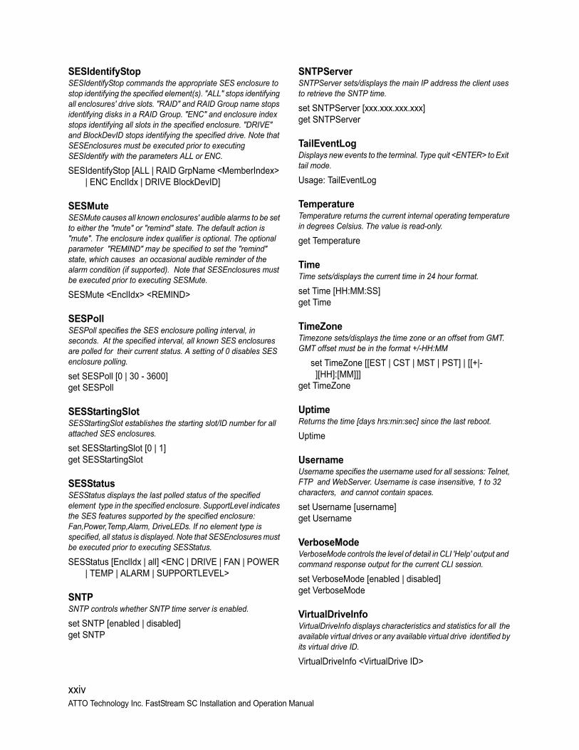
SESIdentifyStop SESIdentifyStop commands the appropriate SES enclosure to stop identifying the specified element(s). "ALL" stops identifying all enclosures' drive slots. "RAID" and RAID Group name stops identifying disks in a RAID Group. "ENC" and enclosure index stops identifying all slots in the specified enclosure. "DRIVE" and BlockDevID stops identifying the specified drive. Note that SESEnclosures must be executed prior to executing SESIdentify with the parameters ALL or ENC.
SESIdentifyStop [ALL | RAID GrpName <MemberIndex> | ENC EnclIdx | DRIVE BlockDevID]
SESMuteSESMute causes all known enclosures' audible alarms to be set to either the "mute" or "remind" state. The default action is "mute". The enclosure index qualifier is optional. The optional parameter "REMIND" may be specified to set the "remind" state, which causes an occasional audible reminder of the alarm condition (if supported). Note that SESEnclosures must be executed prior to executing SESMute.
SESMute <EnclIdx> <REMIND>
SESPoll SESPoll specifies the SES enclosure polling interval, in seconds. At the specified interval, all known SES enclosures are polled for their current status. A setting of 0 disables SES enclosure polling.
set SESPoll [0 | 30 - 3600]get SESPoll
SESStartingSlotSESStartingSlot establishes the starting slot/ID number for all attached SES enclosures.
set SESStartingSlot [0 | 1]get SESStartingSlot
SESStatus SESStatus displays the last polled status of the specified element type in the specified enclosure. SupportLevel indicates the SES features supported by the specified enclosure: Fan,Power,Temp,Alarm, DriveLEDs. If no element type is specified, all status is displayed. Note that SESEnclosures must be executed prior to executing SESStatus.
SESStatus [EnclIdx | all] <ENC | DRIVE | FAN | POWER | TEMP | ALARM | SUPPORTLEVEL>
SNTPSNTP controls whether SNTP time server is enabled.
set SNTP [enabled | disabled]get SNTP
SNTPServerSNTPServer sets/displays the main IP address the client uses to retrieve the SNTP time.
set SNTPServer [xxx.xxx.xxx.xxx]get SNTPServer
TailEventLogDisplays new events to the terminal. Type quit <ENTER> to Exit tail mode.
Usage: TailEventLog
Temperature Temperature returns the current internal operating temperature in degrees Celsius. The value is read-only.
get Temperature
TimeTime sets/displays the current time in 24 hour format.
set Time [HH:MM:SS]get Time
TimeZoneTimezone sets/displays the time zone or an offset from GMT. GMT offset must be in the format +/-HH:MM
set TimeZone [[EST | CST | MST | PST] | [[+|-][HH]:[MM]]]
get TimeZone
UptimeReturns the time [days hrs:min:sec] since the last reboot.
Uptime
UsernameUsername specifies the username used for all sessions: Telnet, FTP and WebServer. Username is case insensitive, 1 to 32 characters, and cannot contain spaces.
set Username [username]get Username
VerboseModeVerboseMode controls the level of detail in CLI 'Help' output and command response output for the current CLI session.
set VerboseMode [enabled | disabled]get VerboseMode
VirtualDriveInfoVirtualDriveInfo displays characteristics and statistics for all the available virtual drives or any available virtual drive identified by its virtual drive ID.
VirtualDriveInfo <VirtualDrive ID>
xxiv ATTO Technology Inc. FastStream SC Installation and Operation Manual

WrapEventLogWrapEventLog is used to enable/disable event log wrapping. When enabled, 2048 event entries will be logged before wrapping. When disabled, event logging will cease when the log buffer is full.
set WrapEventLog [enabled | disabled]get WrapEventLog
ZmodemZmodem uses the ZMODEM protocol to transfer a file via the RS-232 port. The filename to retrieve is required if the 'send' option is specified.
Usage: Zmodem [[send [filename]] | receive]
xxv

xxviiATTO Technology Inc. FastStream SC Installation and Operation Manual
Appendix E FibreBridge LEDsThis section contains information about LED placement on the FibreBridge embedded RAID controller. The board is setup to use light pipes to bring LEDs out to the enclosure. Future firmware updates will provide a pinout for a POS header that will drive LED functionality.
LEDs on the connector side are:Ready/Fault LED lights green to indicate ready, lights yellow to show a faulted condition, and is off to indicate not ready.
Ethernet port connector: The right green LED shows a valid link, off indicates that no link is present, and blinking indicates activity. The left green LED indicates 100/1000 MbE speed.
SAS/SATA Device: A green LED lit on indicates activity and off means no activity.
SAS Host: A green LED lit on indicates activity and off means no activity.
Available LEDs are:A Ready LED is lighted green to indicate ready and off to show not ready.
An Alert LED is lighted yellow to show an alert condition.
Power: A lighted green LED indicates power has been turned on to the appliance.
SAS Host: A green LED on each connector indicates activity if it is lit.
SAS/SATA device: A green LED on each connector indicates activity if it is lit.
Exhibit H-1 FibreBridge 6500E DIMs LEDS
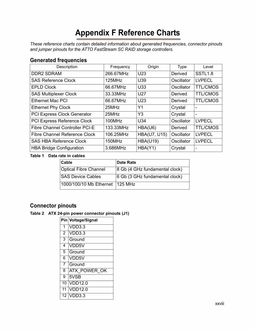
Appendix F Reference ChartsThese reference charts contain detailed information about generated frequencies, connector pinouts and jumper pinouts for the ATTO FastStream SC RAID storage controllers.
Generated frequencies
Connector pinouts
Description Frequency Origin Type Level
DDR2 SDRAM 266.67MHz U23 Derived SSTL1.8
SAS Reference Clock 125MHz U39 Oscillator LVPECL
EPLD Clock 66.67MHz U33 Oscillator TTL/CMOS
SAS Multiplexer Clock 33.33MHz U27 Derived TTL/CMOS
Ethernet Mac PCI 66.67MHz U23 Derived TTL/CMOS
Ethernet Phy Clock 25MHz Y1 Crystal -
PCI Express Clock Generator 25MHz Y3 Crystal -
PCI Express Reference Clock 100MHz U34 Oscillator LVPECL
Fibre Channel Controller PCI-E 133.33MHz HBA(U6) Derived TTL/CMOS
Fibre Channel Reference Clock 106.25MHz HBA(U7, U15) Oscillator LVPECL
SAS HBA Reference Clock 150MHz HBA(U19) Oscillator LVPECL
HBA Bridge Configuration 3.686MHz HBA(Y1) Crystal -
Table 1 Data rate in cables
Cable Date Rate
Optical Fibre Channel 8 Gb (4 GHz fundamental clock)
SAS Device Cables 6 Gb (3 GHz fundamental clock)
1000/100/10 Mb Ethernet 125 MHz
Table 2 ATX 24-pin power connector pinouts (J1)
Pin Voltage/Signal
1 VDD3.32 VDD3.33 Ground4 VDD5V5 Ground6 VDD5V7 Ground8 ATX_POWER_OK9 5VSB10 VDD12.011 VDD12.012 VDD3.3
xxviii
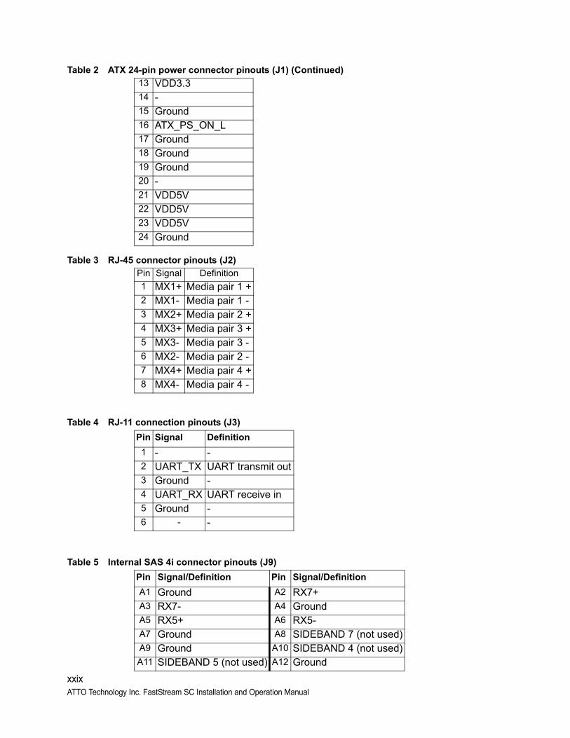
13 VDD3.314 -15 Ground16 ATX_PS_ON_L17 Ground18 Ground19 Ground20 -21 VDD5V22 VDD5V23 VDD5V24 Ground
Table 3 RJ-45 connector pinouts (J2)
Pin Signal Definition
1 MX1+ Media pair 1 +2 MX1- Media pair 1 -3 MX2+ Media pair 2 +4 MX3+ Media pair 3 +5 MX3- Media pair 3 -6 MX2- Media pair 2 -7 MX4+ Media pair 4 +8 MX4- Media pair 4 -
Table 4 RJ-11 connection pinouts (J3)
Pin Signal Definition
1 - -2 UART_TX UART transmit out3 Ground -4 UART_RX UART receive in5 Ground -6 - -
Table 5 Internal SAS 4i connector pinouts (J9)
Pin Signal/Definition Pin Signal/Definition
A1 Ground A2 RX7+A3 RX7- A4 GroundA5 RX5+ A6 RX5-A7 Ground A8 SIDEBAND 7 (not used)A9 Ground A10 SIDEBAND 4 (not used)A11 SIDEBAND 5 (not used) A12 Ground
Table 2 ATX 24-pin power connector pinouts (J1) (Continued)
xxixATTO Technology Inc. FastStream SC Installation and Operation Manual
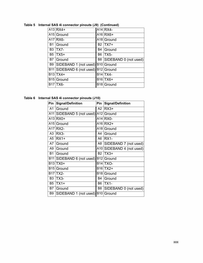
A13 RX4+ A14 RX4-A15 Ground A16 RX6+A17 RX6- A18 GroundB1 Ground B2 TX7+B3 TX7- B4 GroundB5 TX5+ B6 TX5-B7 Ground B8 SIDEBAND 0 (not used)B9 SIDEBAND 1 (not used) B10 GroundB11 SIDEBAND 6 (not used) B12 GroundB13 TX4+ B14 TX4-B15 Ground B16 TX6+B17 TX6- B18 Ground
Table 6 Internal SAS 4i connector pinouts (J10)
Pin Signal/Definition Pin Signal/Definition
A1 Ground A2 RX3+A11 SIDEBAND 5 (not used) A12 GroundA13 RX0+ A14 RX0-A15 Ground A16 RX2+A17 RX2- A18 GroundA3 RX3- A4 GroundA5 RX1+ A6 RX1-A7 Ground A8 SIDEBAND 7 (not used)A9 Ground A10 SIDEBAND 4 (not used)B1 Ground B2 TX3+B11 SIDEBAND 6 (not used) B12 GroundB13 TX0+ B14 TXO-B15 Ground B16 TX2+B17 TX2- B18 GroundB3 TX3- B4 GroundB5 TX1+ B6 TX1-B7 Ground B8 SIDEBAND 0 (not used)B9 SIDEBAND 1 (not used) B10 Ground
Table 5 Internal SAS 4i connector pinouts (J9) (Continued)
xxx
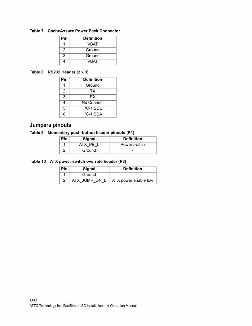
Table 7 CacheAssure Power Pack Connector
Table 8 RS232 Header (2 x 3)
Jumpers pinouts
Table 10 ATX power switch override header (P3)
Pin Definition
1 VBAT
2 Ground
3 Ground
4 VBAT
Pin Definition
1 Ground
2 TX
3 RX
4 No Connect
5 I²C-1 SCL
6 I²C-1 SDA
Table 9 Momentary push-button header pinouts (P1)
Pin Signal Definition
1 ATX_PB_L Power switch
2 Ground -
Pin Signal Definition
1 Ground -
2 ATX_JUMP_ON_L ATX power enable low
xxxiATTO Technology Inc. FastStream SC Installation and Operation Manual

xxxii
Appendix G Standards and CompliancesThe equipment described in this manual generates and uses radio frequency energy. If this equipment is not used in strict accordance with the manufacturer's instruction, it can cause interference with radio and television reception. See the ATTO FastStream Technical Specification sheet for your particular model for a full list of certifications for that model.
FCC Standards: Radio and Television InterferenceThis equipment has been tested and found to comply with the limits for a Class B digital device pursuant to part 15 of the FCC rules. These limits are designed to provide reasonable protection against harmful interference in a residential
installation. This equipment generates, uses and can radiate radio frequency energy and, if not installed and used in accordance with the instructions, may cause harmful interference to radio communication. However, there is no guarantee that interference will not occur in a particular installation.
If this equipment does cause harmful interference to radio and television reception, which can be determined by turning the equipment off and on, the user is encouraged to try to correct the interference by one or more of the following measures:
• Reorient or relocate the receiving antenna.
• Increase the separation between the equipment and the receiver.
• Connect the equipment into an outlet on a circuit different from that to which the receiver is connected.
• If necessary, consult an ATTO authorized dealer, ATTO Technical Support Staff, or an experienced radio/television technician for additional suggestions.
Canadian StandardsThis Class B digital apparatus complies with Canadian ICES-003.
Cet appareil numérique de la classe B est conforme à la norme NMB-003 du Canada.
European StandardsDeclaration of ConformityThis device has been tested in the basic operating configuration and found to be compliant with the following European Union standards:
Application of Council Directive: 2004/108/EC
Standard(s) to which conformity is declared: EN55022, (CISPR 22) / EN55024 (CISPR24)
This Declaration will only be valid when this product is used in conjunction with other CE approved devices and when the entire system is tested to the applicable CE standards and found to be compliant.
The ATTO FastStream complies with Directive 2002/95/EC on the Restriction of the Use of Hazardous Substances in Electrical and Electronic Equipment (RoHS).
xxxiiiATTO Technology Inc. FastStream SC Installation and Operation Manual
Appendix H WarrantyManufacturer limited warranty
Manufacturer warrants to the original purchaser of this product that it is free from defects in material and workmanship as described in the ATTO Technology website, www.attotech.com. Manufacturer liability shall be limited to replacing or repairing, at its option, any defective product. There is no charge for parts or labor should Manufacturer determine that this product is defective.
Products which have been subject to abuse, misuse, alteration, neglected, or have been serviced, repaired or installed by unauthorized personnel shall not be covered under this warranty provision. Damage resulting from incorrect connection or an inappropriate application of this product shall not be the responsibility of Manufacturer. Manufacturer’s liability is limited to Manufacturer’s product(s); damage to other equipment connected to Manufacturer’s product(s) is the customer’s responsibility.
This warranty is made in lieu of any other warranty, express or implied. Manufacturer disclaims any implied warranties of merchantability or fitness for a particular purpose. Manufacturer’s responsibility to repair or replace a defective product is the sole and exclusive remedy provided to the customer for breech of this warranty. Manufacturer is not liable for any indirect, special, incidental, or consequential damages irrespective of whether Manufacturer has advance notice of the possibility of such damages. No Manufacturer dealer, agent or employee is authorized to make any modification, extension or addition to this warranty.