Embed Size (px)
Citation preview

ARCHAEOLOGICAL SURVEY REPORT______________________________________
Gorse Motors Ltd., Gorse Industrial Estate, BarnhamBNH 061
A REPORT ON THE ARCHAEOLOGICAL SURVEY, 2005
John DuffyField Team
Suffolk C.C. Archaeological Service
© March 2005
Lucy Robinson, County Director of Environment and TransportEndeavour House, Russel Road, Ipswich, IP1 2BX
______________________________________SCCAS Report No. 2005/40


i
ContentsList of FiguresList of ContributorsAcknowledgementsSummarySMR information
IntroductionMethodologyResultsDiscussionRecommendationsDisclaimer
Appendix 1: Brief
List of Figures
1. Survey location2. Plan of survey area3. General view looking south-east4. General view looking north-west5. Surface looking north6. Surface looking south7. South-west corner of platform8. South-east corner of platform9. Slot detail west end10. Slot detail east end11. North-west corner detail12. Rectangular opening detail13. South-east corner damage14. General shot of south elevation (internal)15. Close up of bay (internal)16. East wall (internal)17. West wall (internal)18. South elevation (external)19. South elevation detail (external)20. East elevation (external)21. Reconstruction sketch of fuel tank and concrete surface
ii
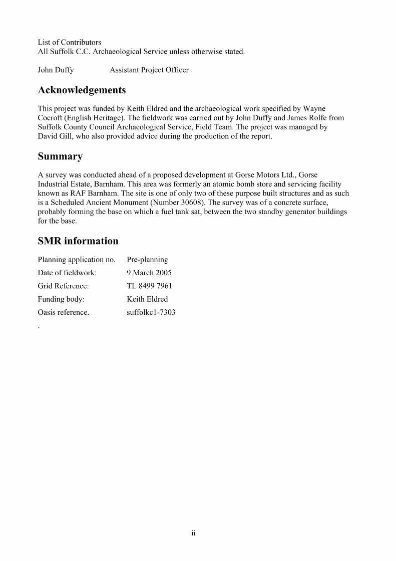
List of ContributorsAll Suffolk C.C. Archaeological Service unless otherwise stated.
John Duffy Assistant Project Officer
Acknowledgements
This project was funded by Keith Eldred and the archaeological work specified by WayneCocroft (English Heritage). The fieldwork was carried out by John Duffy and James Rolfe fromSuffolk County Council Archaeological Service, Field Team. The project was managed byDavid Gill, who also provided advice during the production of the report.
Summary
A survey was conducted ahead of a proposed development at Gorse Motors Ltd., GorseIndustrial Estate, Barnham. This area was formerly an atomic bomb store and servicing facilityknown as RAF Barnham. The site is one of only two of these purpose built structures and as suchis a Scheduled Ancient Monument (Number 30608). The survey was of a concrete surface,probably forming the base on which a fuel tank sat, between the two standby generator buildingsfor the base.
SMR information
Planning application no. Pre-planning
Date of fieldwork: 9 March 2005
Grid Reference: TL 8499 7961
Funding body: Keith Eldred
Oasis reference. suffolkc1-7303
.

1
Introduction
A survey was undertaken to record a concrete surface, ahead of a proposed development, to thesouth of Gorse Motors Ltd. on the Gorse Industrial Estate. The project brief was prepared byWayne Cocroft (English Heritage). The work was undertaken as a requirement of ScheduledAncient Monument consent in advance of a planning application.
The site is located within the area of RAF Barnham which was formerly an atomic bomb storeand servicing facility and is now the Gorse Industrial Estate. This site was one of two built in theearly 1950s to coincide with the RAF’s first operational atomic weapon ‘Blue Danube’ (Cocroftrecording brief – Appendix 1). The area of RAF Barnham is a Scheduled Ancient Monument(Number 30608).
The concrete surface is located between two standby generator buildings which would providepower for the base if the National Grid supply failed. The concrete surface is thought to possiblyform the base for a fuel tank between the two generator buildings.
400m200m0mCrown Copyright. All Rights Reserved.Suffolk County Council Licence No. 100023395 2005
Figure 1 Survey location
SurveyArea

2
MethodologyA photographic record was made of the concrete surface using a digital camera and a medium format camera withmonochrome film. Photographs were also taken to record the internal and external elevations of the south wall of thenorthern generator building. Internal and external photographs were also taken of the east wall and internalphotographs were taken of the west wall.
The survey was conducted using a Total Station Theodolite (TST). The plan was then produced, using LisCAD andMapInfo, from the surveyed data.
Results
Concrete Surface (Figure 2)
The concrete surface measures 11.6m long, 8.2m wide and 0.15m deep. It is located 4m to thesouth of the northern building and 2.5m north of the southern building. The surface has been castin two halves with the division being along the long axis. The surface is then laid on top of alevel platform built into the natural slope between the two generator buildings. The area to thenorth and east of the platform is built up to form a level surface outside the concrete surface. It isunclear how much of this levelling took place as part of the construction of the concrete surfaceand how much is more recent work to produce a level yard outside the existing building (Figures3 to 6).
The platform on which the concrete surface sits is faced with large concrete blocks, measuring0.45m by 0.23m, under a facing of bricks, measuring 0.22m long, 0.11m wide and 0.07m deep(Figure 7 and 8). The large concrete blocks appear to form a retaining wall for the platform. Thefacing was only visible along the southern edge and the southern half of the western edge of theplatform. This brick facing was only one brick wide and appeared to continue above the level ofthe concrete surface. As the outer bricks continued above the concrete an inner face of brickswere laid on the outer edge of the concrete surface. This would have created a wall, two brickswide, around almost the entire surface. This wall has now been truncated to the level of theconcrete to form a level space outside the building.
The surface contained several internal features, the most notable of which were a series of fiveparallel slots running across almost the entire width of the surface. The best preserved of thesewas the most northerly one (Figures 9 and 10). The slots, measuring 7.5m by 0.4m, appear tohave originally contained further concrete possibly forming the supports for a fuel tank.
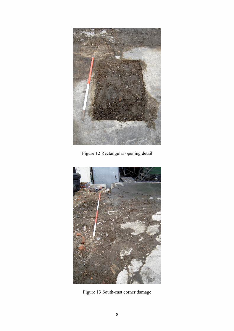
The north-west corner of the surface is cut away and is the only area of the surface without anybrick walling (Figure 11). This may well have given access to the walled off area and to the fueltank itself. Another internal feature was a rectangular opening near the northern edge of thesurface (Figure 12). The opening measured 0.9m by 0.6m and may well have been to allow foroutlet pipes for the fuel tank.
During the survey the extent of damage to the concrete surface was also recorded. There isextensive damage across the entire surface, which appears to be from general usage. However,there is also considerable damage along the eastern edge of the surface where over half of theeastern edge has been destroyed (Figure 13).

3
Area of Build UpBehind Surface
Fence Line
Concrete Surface
Edge of Build Up
South Generator Building
(now T&B Blasting)
North Generator Building
(now Gorse Motors Ltd)
Rectangular Opening
Outer Face of Bricks
Inner Face of Bricks
10m
Line of Slot (surviving)
Line of Slot (not surviving)
Limits of Damage
Centre Line
Limit of Surface
Legend
5m
Scale
Fence Line
0m
Figure 2 Plan of survey area
Figure 3 General view looking south-east

4
Figure 4 General view looking north-west
Figure 5 Surface looking north

5
Figure 6 Surface looking south
Figure 7 South-west corner of platform

6
Figure 8 South-east corner of platform
Figure 9 Slot detail west end

7
Figure 10 Slot detail east end
Figure 11 North-west corner detail
8
Figure 12 Rectangular opening detail
Figure 13 South-east corner damage
9
Building ElevationsInternal
The internal elevation of the south wall of the north building (now Gorse Motors Ltd) is made upof four bays (Figure 14). Each bay is identical with a single window per bay (Figure 15). Withinthe proposed development a doorway will be inserted through one of these bays to connect to anew building to the south.
Record photographs were also made of the internal face of the east wall (Figure 16). The door tothe new building may not placed in the south wall, if so, then it may be inserted through the eastwall. The east wall, at the time of the survey, is covered in the machinery of the existing garageand a full photographic record could not be completed.
A photographic record was also made of the internal face of the west wall (Figure 17). Thisrecord was made to indicate the large cracks in the building fabric above the main garageentrance. This appears to have been caused by the insertion of steel beams extending from theeast wall to the west wall.
External
A record of the external face of the south elevation on the northern building was also made(Figure 18). However, the elevation is fully rendered and the only identifiable features were thewindows. On the south-west corner of the building some of the render had fallen off and theunderlying brick work was visible (Figure 19). The brickwork was too damaged to allow detailedrecording.
A record was also made of the external face of the east wall (Figure 20). The remains of anextension to the building are clearly visible though the extent is unknown. However, theproximity of the fence line gives at least an indication of its maximum size.

10
Figure 14 General shot of south elevation (internal)
Figure 15 Close up of bay (internal)

11
Figure 16 East wall (internal)
Figure 17 West wall (internal)(area of cracking highlighted by the circle)

12
Figure 18 South elevation (external)
Figure 19 South elevation detail (external)

13
Figure 20 East elevation (external)

14
Discussion
The results of the survey show the extent and condition of the concrete surface. The results alsoindicate that the concrete surface, and the platform it was built on, was the structure probablysupporting a fuel tank. The location between the two former generator buildings is another strongargument for the presence of a fuel tank.
The proposed fuel tank appears to have rested on five concrete supports built into the survivingconcrete base. This concrete base also had an opening, probably for an outlet pipe. The fuel tankand the concrete surface it sat on were surrounded by a brick wall. The original height of the wallis unknown though it seems likely that this was an enclosing low wall rather than a full structure,possibly designed to contain fuel spillages (Figure 21).
Figure 21 Reconstruction sketch of fuel tank and concrete surface
The concrete surface sat on a platform surrounded by a retaining wall of large concrete blocks(Figure 21). The exact nature of the platform could not be determined during this survey. Theplatform may be built by terracing the natural slope or it may be formed using a build-up ofdumped material or a combination of both. There is also the possibility that the platform wasfree-standing as the extent of the concrete block retaining wall has not been determined.
Little is known about how the concrete surface relates to the surrounding buildings. The surfaceis level with the northern building but is substantially higher than the southern building. If thiswas the site of a fuel tank and both the north and south buildings housed generators then it isunclear how the fuel was fed from the tank to the generator buildings. It is possible, as wasmentioned earlier, that the rectangular opening was for an outlet pipe. If this is the case it mayhave lead to both generators or only the north one. Further work would be necessary tounderstand the relationship and the workings of the three structures and any further structures inthe vicinity need to be identified.
Fuel tank
Concrete support
Concrete surface
Platform build up
Concrete blocks
Brick wall

15
Recommendations
Although the survey of the concrete surface has provided a detailed record of both the surfaceand the buildings around it, there is still more to understand about the remains on this site. Thisincludes the concrete surface and the platform on which it is laid, as well as the build-up outsidethe platform. Any work affecting the fabric of the standing building will also need recording.
Concrete surface and platform
At present it is unclear exactly how the platform was constructed and what was happeningaround it. Further work needs to be done to understand the make up of the ground around theplatform and identifying how much is part of an original surface and how much is more recentbuild-up. A small trench along the eastern edge of the concrete surface should help determine thenature of the external build-up and may add to our understanding of the construction of theplatform.
Further work on the concrete surface and its platform would also be beneficial. More could beunderstood about how the site functioned and was constructed. Excavation within the rectangularopening and around the cut away corner at the northern edge of the surface would help in theunderstanding how the site functioned. Furthermore if pipes exist in this area this may haveimplications on the development and the identification and recording of these would minimisetheir impact on the new building.
Existing building
Any work directly affecting the standing building to the north of the platform would requiremonitoring. The insertion of a doorway will destroy part of the fabric of the building and shouldbe recorded.
If, as briefly mentioned earlier, the link to the new building goes through the east wall instead ofthe south wall then this will impact not only on the fabric of the standing building but also thenow largely demolished extension. If this became the preferred option then work should beundertaken to identify and record any remains on the eastern side of the building.

16
Disclaimer
Any opinions expressed in this report about the need for further archaeological work are those ofthe Field Projects Division alone. The need for further work will be determined by the LocalPlanning Authority and its archaeological advisors when a planning application is registered.Suffolk County Council’s archaeological contracting service cannot accept responsibility forinconvenience caused to clients should the Planning Authority take a different view to thatexpressed in the report.

Appendix 1
17
Recording brief
Gorse Industrial Estate, Eleveden Road, Barnham, Suffolk, IP24 2PH
Scheduled Monument National Number:- 30608
Concrete floor surface – between the two former stand-by generator buildings
8 February 2005
Introduction
The former atomic bomb store and servicing facility at RAF Barnham (now theGorse Industrial Estate) was one of two purpose-built facilities constructed inthe early 1950s to coincide with the deployment of the RAF’s first operationalatomic weapon ‘Blue Danube’. The whole site within, and including, itsoriginal boundary fence is a Scheduled Monument.
This recording brief was produced in response to a proposal to partly orwholly remove a concrete floor surface between the two standby generatorbuildings at the entrance to the site. If the supply of electricity from theNational Grid was lost, the standby generators formed an essential part of theoperation of the site to provide it with electrical power.
Condition
The feature under threat comprises a concrete floor slab surrounded by the footings ofa brick wall. It is unclear if this feature represents a demolished building or theremains of a low brick bund wall around a fuel storage facility.
Background to Recording Brief
In February 2005, English Heritage was informed that the garage (which currentlyoccupies the northern most of the former generator buildings) wished to erect a semi-temporary structure to its south, and to join it to the existing building by a doorinserted in the southern elevation of the generator building. It was considered thatthis work would have the beneficial effect of sustaining the existing building ineconomic use and would have minimal effect on the interpretation of the site. Theground works for the semi-temporary structure will, however, damage or partlyremove a concrete floor; this brief is designed to ensure that an adequate record isproduced of this feature prior to any ground works ground works taking place.

Appendix 1
18
Recording brief
The main aim of the report is to provide a concise record of the concrete floor.
Prior to recording any loose soil or debris should be removed from the floor surface.
Suggested report contents:-
1 A short written description of the concrete floor.
2 A metrically accurate plan of the concrete floor drawn at a scale sufficientlylarge to show the scars and other significant features on its surface. This willalso show the floor slab in relation to the generator building to the north andthe boundary fence.
3 Photographs of the concrete footing and images to illustrate its site context.
4 General exterior photograph of the northern most former generator buildingand details photographs of its southern elevation (externally and internally)
5 Copies of the report will be deposited with the English Heritage, NationalMonuments Record, Swindon and Suffolk County Council HistoricEnvironment Record.
Sources
Cocroft, W D 1998 RAF Barnham, Suffolk. RCHME typescript survey report NMRTL 87 NE 46
Cocroft, W D 2001 Cold War monuments: an assessment by the MonumentsProtection Programme. London: English Heritage - typescript report available on CD
Cocroft, W D & Thomas, R J C 2003 Cold War: Building for nuclear confrontation1946-1989. London: English Heritage
Wayne CocroftSenior Archaeological Investigator, Research DepartmentEnglish HeritageBrooklands, 24 Brooklands AvenueCambridge, CB2 2BU
Direct: 01223 583770 Office: 01223 582700