Embed Size (px)
Citation preview
Page 1 of 15 © Aquaveo
ARC HYDRO GROUNDWATER TUTORIALS
Subsurface Analyst – Creating rasters from cross sections
Arc Hydro Groundwater (AHGW) is a geodatabase design for representing groundwater
datasets within ArcGIS. The data model helps to archive, display, and analyze
multidimensional groundwater data, and includes several components to represent different
types of datasets, including representations of aquifers and wells/boreholes, 3D
hydrogeologic models, temporal information, and data from simulation models. The Arc
Hydro Groundwater Tools help to import, edit, and manage groundwater data stored in an
AHGW geodatabase. Subsurface Analyst is a subset of the AHGW Tools that is used to
manage 2D and 3D hydrogeologic data, and create subsurface models including generation
of borehole representations, cross sections, surfaces, and volumes.
In this tutorial we will demonstrate how 3D hydrogeologic models can be modified by
including new data points derived from cross sections. We will use the GeoSections To
Points tool and include the output points to interpolate new rasters. The rasters are then
loaded into a raster catalog and used to create volume and cross sections. The process of
creating GeoSections from sketched 2D cross sections is illustrated in separate tutorials.
1.1 Background
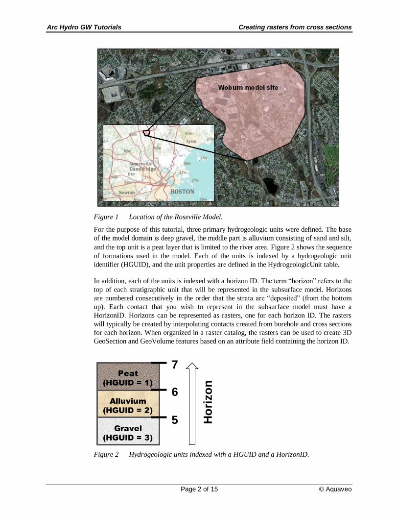
Data used in this tutorial are based on data from a study in the city of Woburn conducted
by the USGS. The data were modified for the purposes of the tutorial. The site location is
shown in Figure 1.
Arc Hydro GW Tutorials Creating rasters from cross sections
Page 2 of 15 © Aquaveo
Figure 1 Location of the Roseville Model.
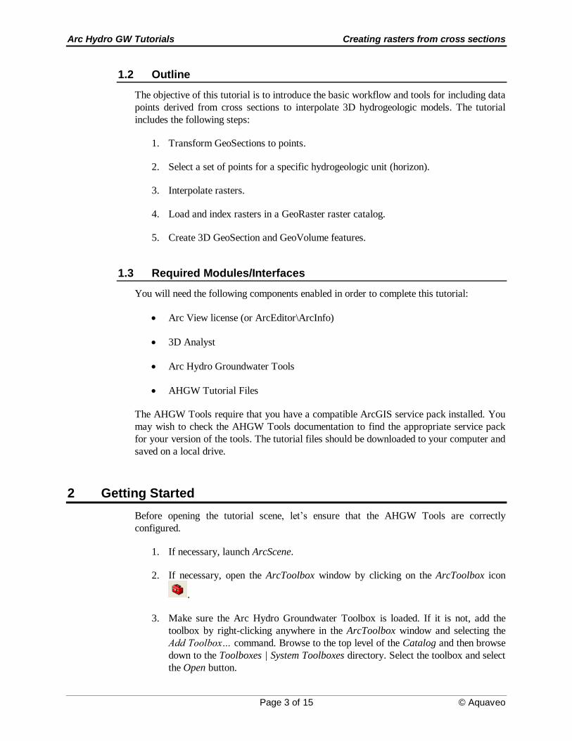
For the purpose of this tutorial, three primary hydrogeologic units were defined. The base
of the model domain is deep gravel, the middle part is alluvium consisting of sand and silt,
and the top unit is a peat layer that is limited to the river area. Figure 2 shows the sequence
of formations used in the model. Each of the units is indexed by a hydrogeologic unit
identifier (HGUID), and the unit properties are defined in the HydrogeologicUnit table.
In addition, each of the units is indexed with a horizon ID. The term “horizon” refers to the
top of each stratigraphic unit that will be represented in the subsurface model. Horizons
are numbered consecutively in the order that the strata are “deposited” (from the bottom
up). Each contact that you wish to represent in the subsurface model must have a
HorizonID. Horizons can be represented as rasters, one for each horizon ID. The rasters
will typically be created by interpolating contacts created from borehole and cross sections
for each horizon. When organized in a raster catalog, the rasters can be used to create 3D
GeoSection and GeoVolume features based on an attribute field containing the horizon ID.
Peat
(HGUID = 1)
Alluvium
(HGUID = 2)
Gravel
(HGUID = 3)
5
6
7
Ho
rizo
n
Figure 2 Hydrogeologic units indexed with a HGUID and a HorizonID.
Arc Hydro GW Tutorials Creating rasters from cross sections
Page 3 of 15 © Aquaveo
1.2 Outline
The objective of this tutorial is to introduce the basic workflow and tools for including data
points derived from cross sections to interpolate 3D hydrogeologic models. The tutorial
includes the following steps:
1. Transform GeoSections to points.
2. Select a set of points for a specific hydrogeologic unit (horizon).
3. Interpolate rasters.
4. Load and index rasters in a GeoRaster raster catalog.
5. Create 3D GeoSection and GeoVolume features.
1.3 Required Modules/Interfaces
You will need the following components enabled in order to complete this tutorial:
Arc View license (or ArcEditor\ArcInfo)
3D Analyst
Arc Hydro Groundwater Tools
AHGW Tutorial Files
The AHGW Tools require that you have a compatible ArcGIS service pack installed. You
may wish to check the AHGW Tools documentation to find the appropriate service pack
for your version of the tools. The tutorial files should be downloaded to your computer and
saved on a local drive.
2 Getting Started
Before opening the tutorial scene, let’s ensure that the AHGW Tools are correctly
configured.
1. If necessary, launch ArcScene.
2. If necessary, open the ArcToolbox window by clicking on the ArcToolbox icon
.
3. Make sure the Arc Hydro Groundwater Toolbox is loaded. If it is not, add the
toolbox by right-clicking anywhere in the ArcToolbox window and selecting the
Add Toolbox… command. Browse to the top level of the Catalog and then browse
down to the Toolboxes | System Toolboxes directory. Select the toolbox and select
the Open button.
Arc Hydro GW Tutorials Creating rasters from cross sections
Page 4 of 15 © Aquaveo
4. Expand the Arc Hydro Groundwater Tools item and then expand the Subsurface
Analyst toolset to expose the tools we will be using in this tutorial.
We will also be using the Arc Hydro Groundwater Toolbar. The toolbar contains
additional user interface components not available in the toolbox. If the toolbar is not
visible, do the following:
5. Right-click on any visible toolbar and select the Arc Hydro Groundwater Toolbar
item.
When using geoprocessing tools you can set the tools to overwrite outputs by default, and
automatically add results to the map/scene. To set these options:
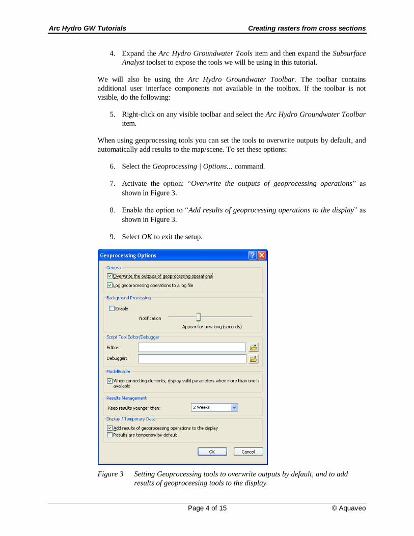
6. Select the Geoprocessing | Options... command.
7. Activate the option: “Overwrite the outputs of geoprocessing operations” as
shown in Figure 3.
8. Enable the option to “Add results of geoprocessing operations to the display” as
shown in Figure 3.
9. Select OK to exit the setup.
Figure 3 Setting Geoprocessing tools to overwrite outputs by default, and to add
results of geoproceesing tools to the display.
Arc Hydro GW Tutorials Creating rasters from cross sections
Page 5 of 15 © Aquaveo
3 Opening the Scene
We will begin by opening a scene containing some background data for the project.
1. Select the File| Open command and browse to the location on your local drive
where you have saved the AHGW tutorials. Browse to the GeoSection to Points
folder and open the file entitled Woburn_geosections_to_points.sxd.
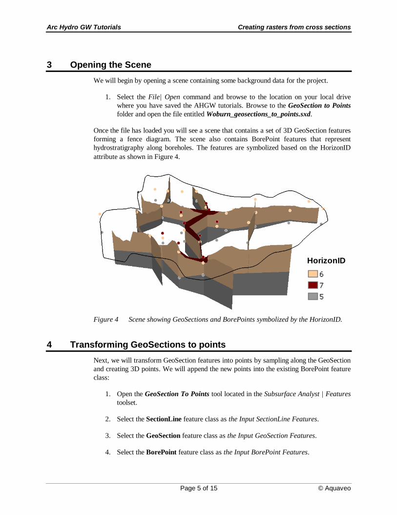
Once the file has loaded you will see a scene that contains a set of 3D GeoSection features
forming a fence diagram. The scene also contains BorePoint features that represent
hydrostratigraphy along boreholes. The features are symbolized based on the HorizonID
attribute as shown in Figure 4.
HorizonID
Figure 4 Scene showing GeoSections and BorePoints symbolized by the HorizonID.
4 Transforming GeoSections to points
Next, we will transform GeoSection features into points by sampling along the GeoSection
and creating 3D points. We will append the new points into the existing BorePoint feature
class:
1. Open the GeoSection To Points tool located in the Subsurface Analyst | Features
toolset.
2. Select the SectionLine feature class as the Input SectionLine Features.
3. Select the GeoSection feature class as the Input GeoSection Features.
4. Select the BorePoint feature class as the Input BorePoint Features.
Arc Hydro GW Tutorials Creating rasters from cross sections
Page 6 of 15 © Aquaveo
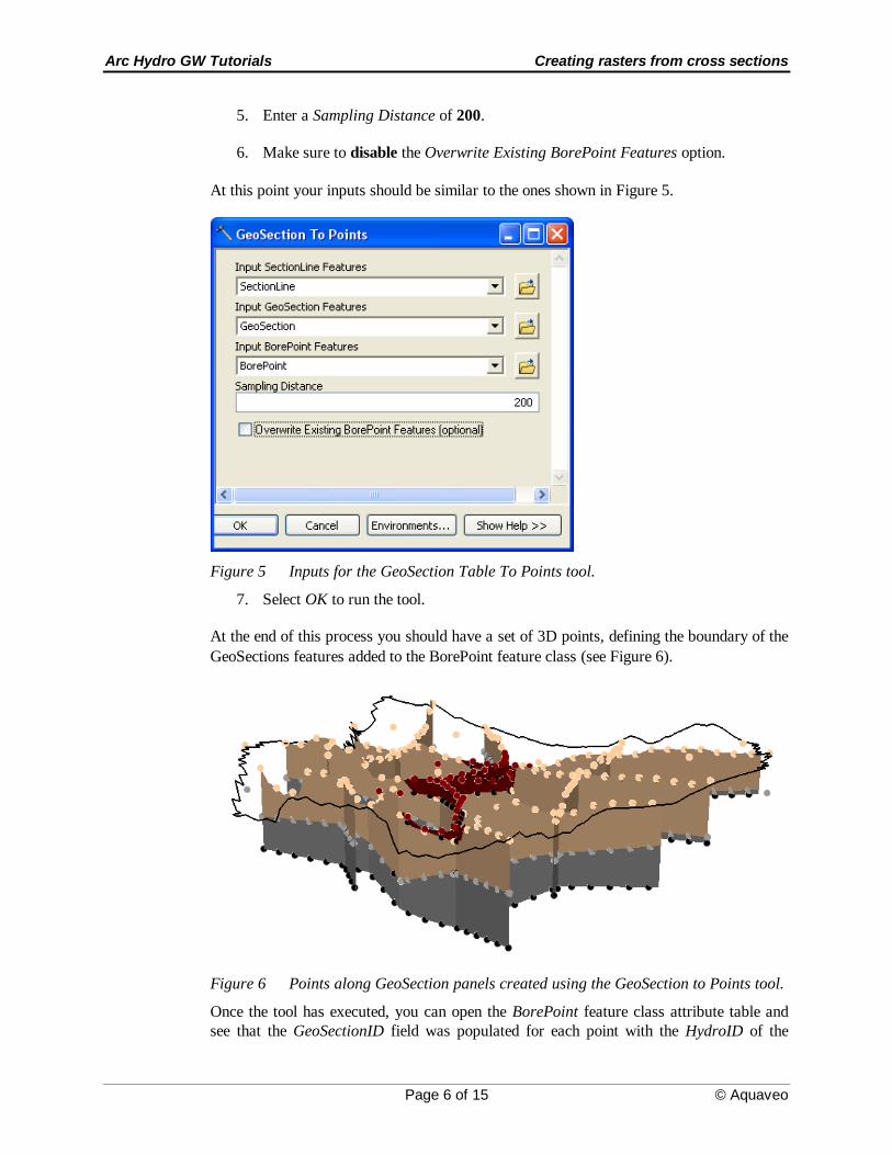
5. Enter a Sampling Distance of 200.
6. Make sure to disable the Overwrite Existing BorePoint Features option.
At this point your inputs should be similar to the ones shown in Figure 5.
Figure 5 Inputs for the GeoSection Table To Points tool.
7. Select OK to run the tool.
At the end of this process you should have a set of 3D points, defining the boundary of the
GeoSections features added to the BorePoint feature class (see Figure 6).
Figure 6 Points along GeoSection panels created using the GeoSection to Points tool.
Once the tool has executed, you can open the BorePoint feature class attribute table and
see that the GeoSectionID field was populated for each point with the HydroID of the
Arc Hydro GW Tutorials Creating rasters from cross sections
Page 7 of 15 © Aquaveo
associated GeoSection panel (the original BorePoint features will not have a GeoSectionID
as they were created from borehole data). Notice that the HGUID field was also populated
with the HGUID of the associated GeoSection panel. Finally, you will note that the
HorizonID attribute of the BorePoint features match those of the GeoSection features they
came from. A negative HorizonID indicates that the point came from the bottom of a
GeoSection feature.
5 Interpolating rasters
We are now ready to interpolate rasters based upon the BorePoint features. This step
requires Spatial Analyst or 3D Analyst extensions. If you do not have either of these
extensions installed, you will not be able to complete this part of the tutorial (you can use
the solution files to view the interpolated rasters). We will use the IDW geoprocessing tool
to perform the interpolation and we will set the Environment options such that the
resulting raster is clipped to the Boundary feature class.
Before we start the interpolation we will filter the points for a selected HorizonID using the
Field Filter available in the AHGW toolbar.
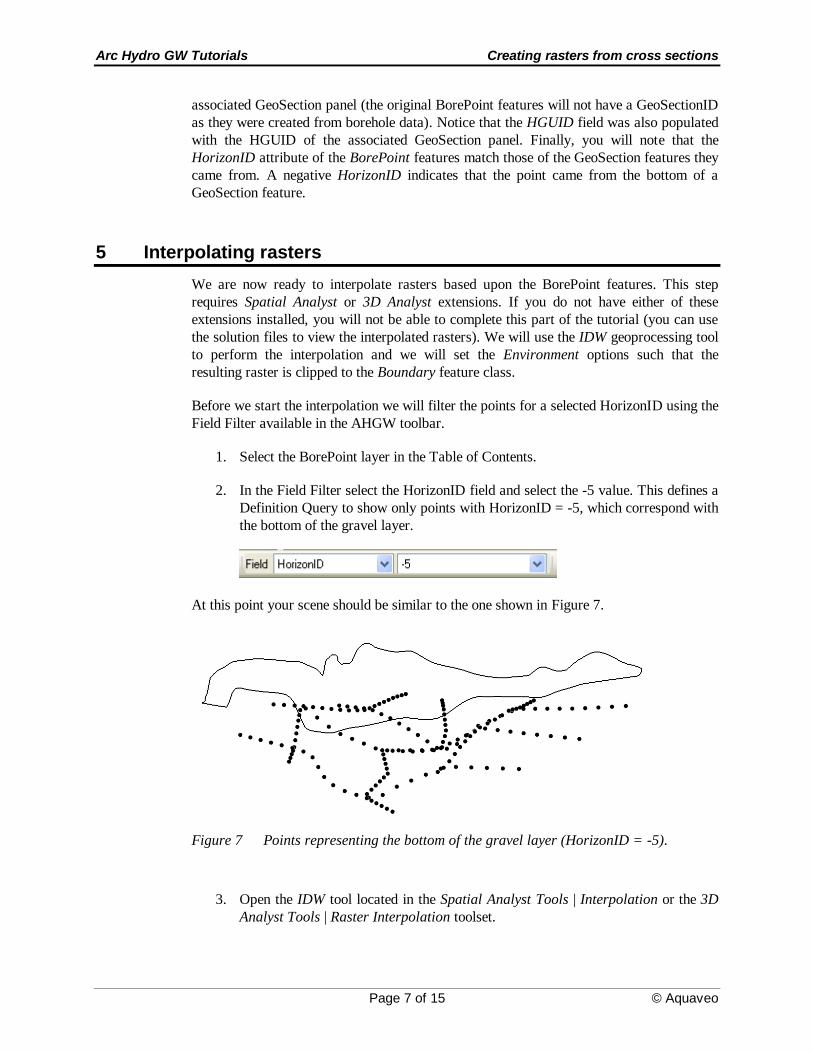
1. Select the BorePoint layer in the Table of Contents.
2. In the Field Filter select the HorizonID field and select the -5 value. This defines a
Definition Query to show only points with HorizonID = -5, which correspond with
the bottom of the gravel layer.
At this point your scene should be similar to the one shown in Figure 7.
Figure 7 Points representing the bottom of the gravel layer (HorizonID = -5).
3. Open the IDW tool located in the Spatial Analyst Tools | Interpolation or the 3D
Analyst Tools | Raster Interpolation toolset.
Arc Hydro GW Tutorials Creating rasters from cross sections
Page 8 of 15 © Aquaveo
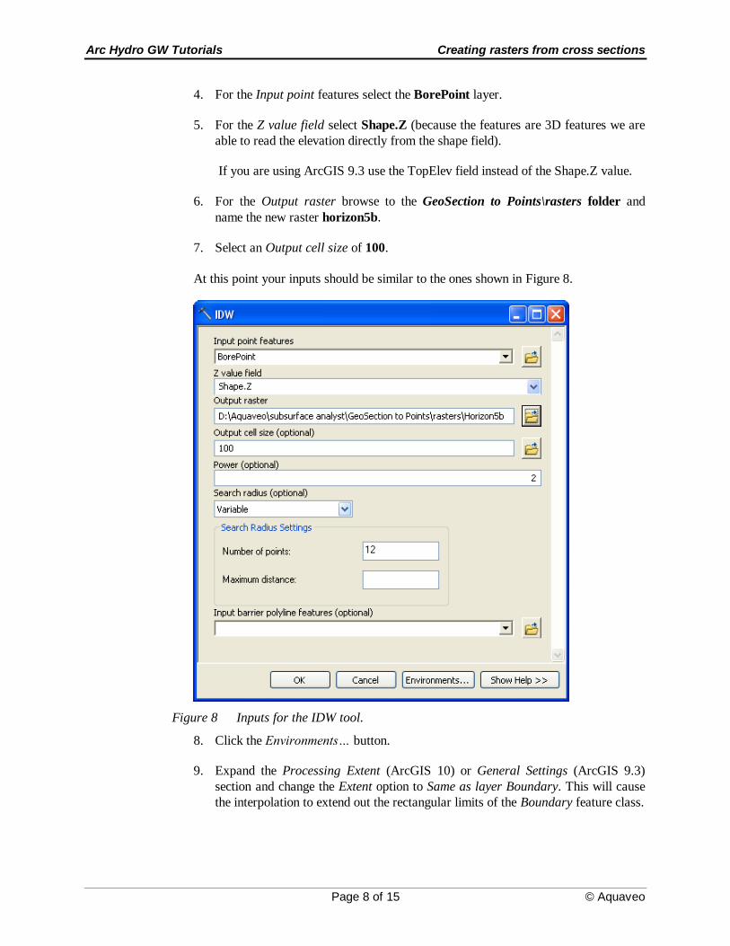
4. For the Input point features select the BorePoint layer.
5. For the Z value field select Shape.Z (because the features are 3D features we are
able to read the elevation directly from the shape field).
If you are using ArcGIS 9.3 use the TopElev field instead of the Shape.Z value.
6. For the Output raster browse to the GeoSection to Points\rasters folder and
name the new raster horizon5b.
7. Select an Output cell size of 100.
At this point your inputs should be similar to the ones shown in Figure 8.
Figure 8 Inputs for the IDW tool.
8. Click the Environments… button.
9. Expand the Processing Extent (ArcGIS 10) or General Settings (ArcGIS 9.3)
section and change the Extent option to Same as layer Boundary. This will cause
the interpolation to extend out the rectangular limits of the Boundary feature class.
Arc Hydro GW Tutorials Creating rasters from cross sections
Page 9 of 15 © Aquaveo
10. Scroll down and expand the Raster Analysis Settings section and change the Mask
to Boundary. This will clip the raster to the actual boundary of the Boundary
feature class.
11. Select the OK button to exit the Environment Settings dialog.
12. Select the OK button to execute the IDW tool.
Note the new raster is added to the display using zero as the display elevation. To
visualize the new raster based on its elevations, we will need to set the Base Height:
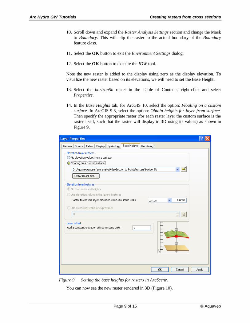
13. Select the horizon5b raster in the Table of Contents, right-click and select
Properties.
14. In the Base Heights tab, for ArcGIS 10, select the option: Floating on a custom
surface. In ArcGIS 9.3, select the option: Obtain heights for layer from surface.
Then specify the appropriate raster (for each raster layer the custom surface is the
raster itself, such that the raster will display in 3D using its values) as shown in
Figure 9.
Figure 9 Setting the base heights for rasters in ArcScene.
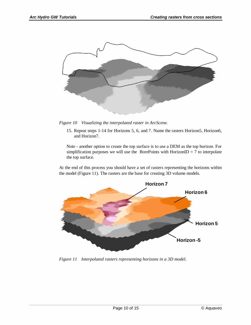
You can now see the new raster rendered in 3D (Figure 10).
Arc Hydro GW Tutorials Creating rasters from cross sections
Page 10 of 15 © Aquaveo
Figure 10 Visualizing the interpolated raster in ArcScene.
15. Repeat steps 1-14 for Horizons 5, 6, and 7. Name the rasters Horizon5, Horizon6,
and Horizon7.
Note - another option to create the top surface is to use a DEM as the top horizon. For
simplification purposes we will use the BorePoints with HorizonID = 7 to interpolate
the top surface.
At the end of this process you should have a set of rasters representing the horizons within
the model (Figure 11). The rasters are the base for creating 3D volume models.
Horizon 7
Horizon 6
Horizon -5
Horizon 5
Figure 11 Interpolated rasters representing horizons in a 3D model.
Arc Hydro GW Tutorials Creating rasters from cross sections
Page 11 of 15 © Aquaveo
6 Loading rasters to the GeoRasters raster catalog
In this step we will load the rasters into a GeoRasters raster catalog and index the rasters
with attributes used later to create 3D GeoSection and GeoVolume features. A more
detailed description of the process including the creation of the raster catalog and an
explanation of the different options is available in a separate tutorial.
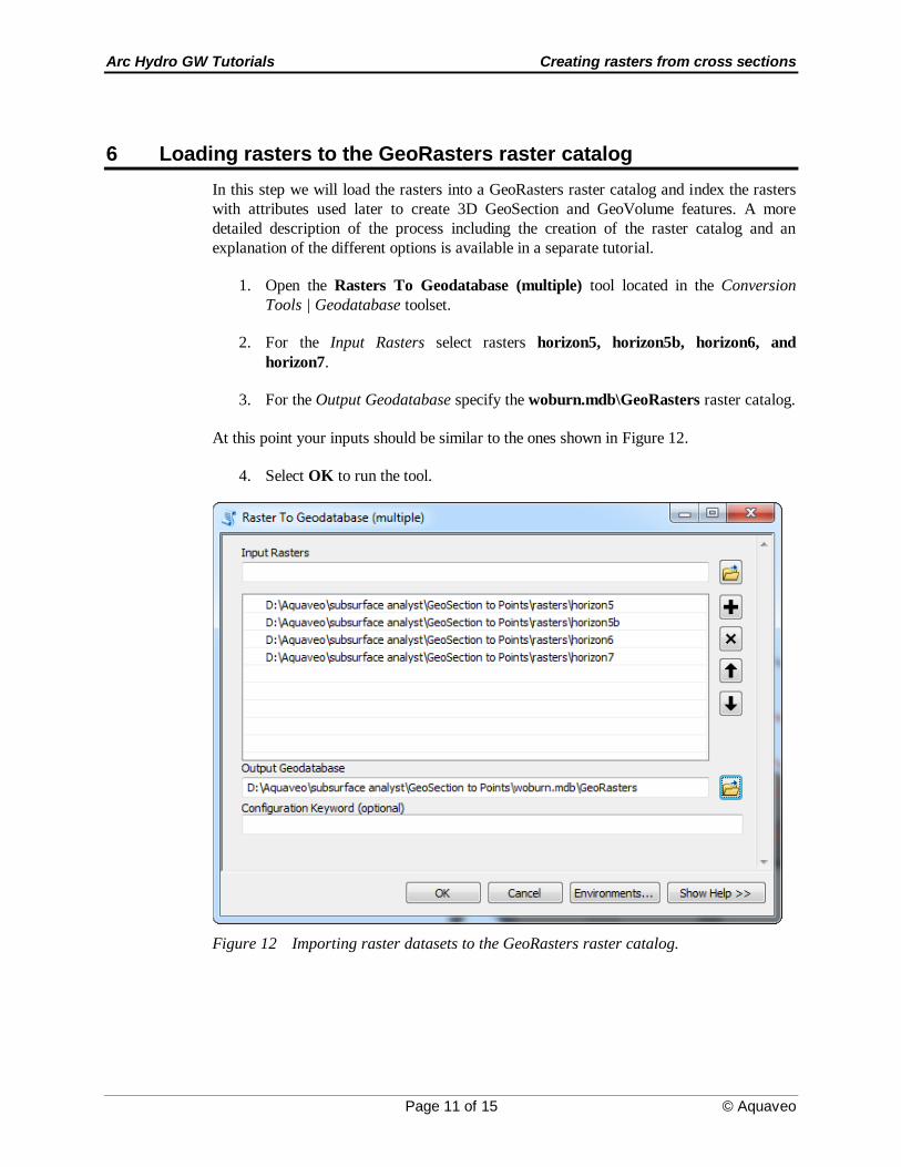
1. Open the Rasters To Geodatabase (multiple) tool located in the Conversion
Tools | Geodatabase toolset.
2. For the Input Rasters select rasters horizon5, horizon5b, horizon6, and
horizon7.
3. For the Output Geodatabase specify the woburn.mdb\GeoRasters raster catalog.
At this point your inputs should be similar to the ones shown in Figure 12.
4. Select OK to run the tool.
Figure 12 Importing raster datasets to the GeoRasters raster catalog.
Arc Hydro GW Tutorials Creating rasters from cross sections
Page 12 of 15 © Aquaveo
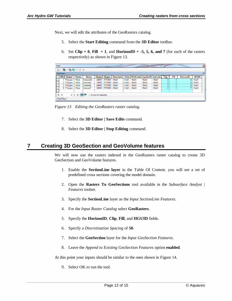
Next, we will edit the attributes of the GeoRasters catalog.
5. Select the Start Editing command from the 3D Editor toolbar.
6. Set Clip = 0, Fill = 1, and HorizonID = -5, 5, 6, and 7 (for each of the rasters
respectively) as shown in Figure 13.
Figure 13 Editing the GeoRasters raster catalog.
7. Select the 3D Editor | Save Edits command.
8. Select the 3D Editor | Stop Editing command.
7 Creating 3D GeoSection and GeoVolume features
We will now use the rasters indexed in the GeoRasters raster catalog to create 3D
GeoSection and GeoVolume features.
1. Enable the SectionLine layer in the Table Of Content. you will see a set of
predefined cross sections covering the model domain.
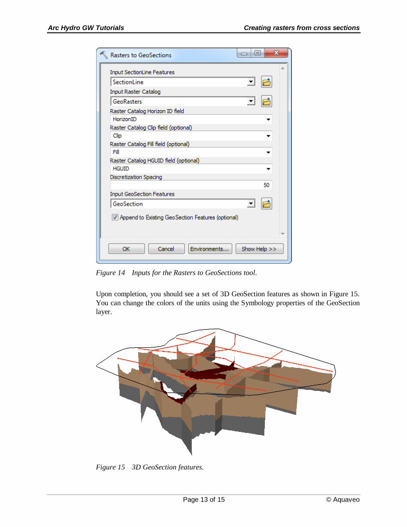
2. Open the Rasters To GeoSections tool available in the Subsurface Analyst |
Features toolset.
3. Specify the SectionLine layer as the Input SectionLine Features.
4. For the Input Raster Catalog select GeoRasters.
5. Specify the HorizonID, Clip, Fill, and HGUID fields.
6. Specify a Discretization Spacing of 50.
7. Select the GeoSection layer for the Input GeoSection Features.
8. Leave the Append to Existing GeoSection Features option enabled.
At this point your inputs should be similar to the ones shown in Figure 14.
9. Select OK to run the tool.
Arc Hydro GW Tutorials Creating rasters from cross sections
Page 13 of 15 © Aquaveo
Figure 14 Inputs for the Rasters to GeoSections tool.
Upon completion, you should see a set of 3D GeoSection features as shown in Figure 15.
You can change the colors of the units using the Symbology properties of the GeoSection
layer.
Figure 15 3D GeoSection features.
Arc Hydro GW Tutorials Creating rasters from cross sections
Page 14 of 15 © Aquaveo
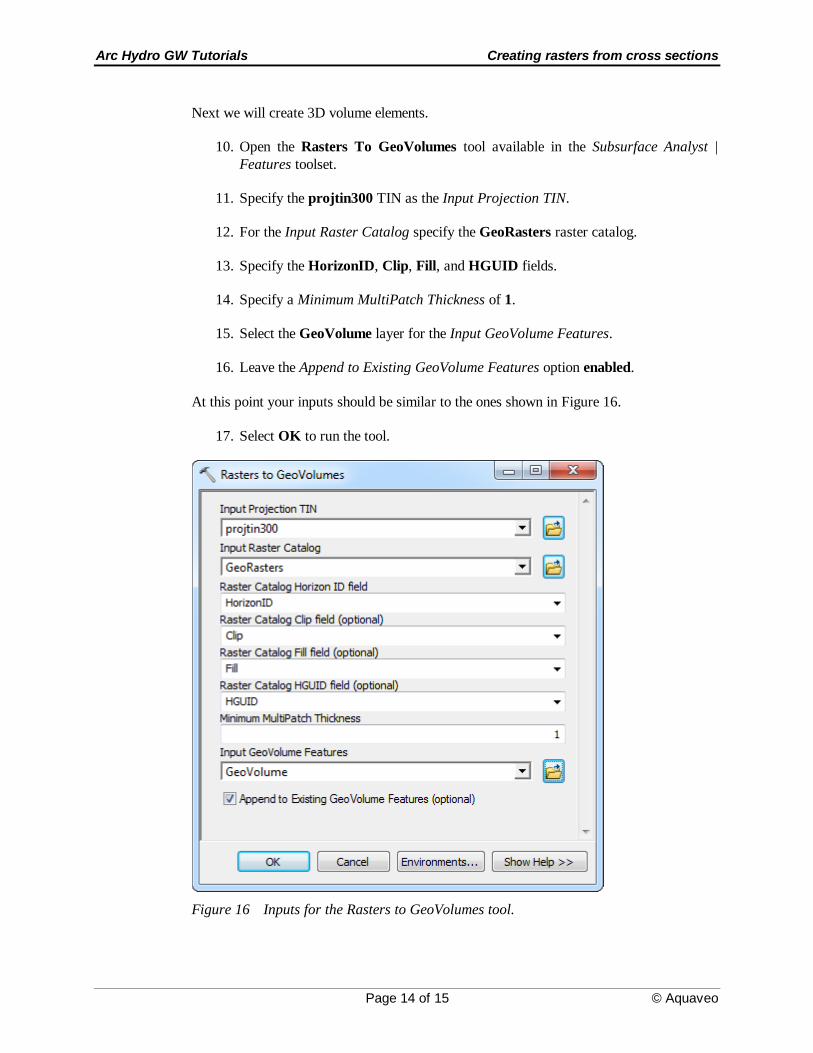
Next we will create 3D volume elements.
10. Open the Rasters To GeoVolumes tool available in the Subsurface Analyst |
Features toolset.
11. Specify the projtin300 TIN as the Input Projection TIN.
12. For the Input Raster Catalog specify the GeoRasters raster catalog.
13. Specify the HorizonID, Clip, Fill, and HGUID fields.
14. Specify a Minimum MultiPatch Thickness of 1.
15. Select the GeoVolume layer for the Input GeoVolume Features.
16. Leave the Append to Existing GeoVolume Features option enabled.
At this point your inputs should be similar to the ones shown in Figure 16.
17. Select OK to run the tool.
Figure 16 Inputs for the Rasters to GeoVolumes tool.
Arc Hydro GW Tutorials Creating rasters from cross sections
Page 15 of 15 © Aquaveo
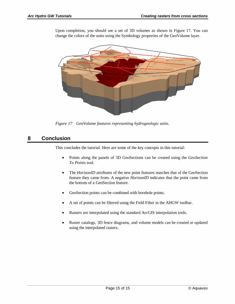
Upon completion, you should see a set of 3D volumes as shown in Figure 17. You can
change the colors of the units using the Symbology properties of the GeoVolume layer.
Figure 17 GeoVolume features representing hydrogeologic units.
8 Conclusion
This concludes the tutorial. Here are some of the key concepts in this tutorial:
Points along the panels of 3D GeoSections can be created using the GeoSection
To Points tool.
The HorizonID attributes of the new point features matches that of the GeoSection
feature they came from. A negative HorizonID indicates that the point came from
the bottom of a GeoSection feature.
GeoSection points can be combined with borehole points.
A set of points can be filtered using the Field Filter in the AHGW toolbar.
Rasters are interpolated using the standard ArcGIS interpolation tools.
Raster catalogs, 3D fence diagrams, and volume models can be created or updated
using the interpolated rasters.