Embed Size (px)
Citation preview
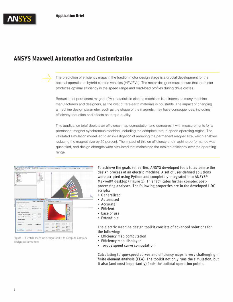
To achieve the goals set earlier, ANSYS developed tools to automate the design process of an electric machine. A set of user-defi ned solutions were scripted using Python and completely integrated into ANSYS® Maxwell® desktop (Figure 1). This facilitates further complex post-processing analyses. The following properties are in the developed UDO scripts:• Generalized• Automated• Accurate• Effi cient • Ease of use• Extendible
The electric machine design toolkit consists of advanced solutions for the following: • Effi ciency map computation• Effi ciency map displayer• Torque speed curve computation
Calculating torque-speed curves and effi ciency maps is very challenging in fi nite element analysis (FEA). The toolkit not only runs the simulation, but it also (and most importantly) fi nds the optimal operation points.
Application Brief
ANSYS Maxwell Automation and Customization
The prediction of effi ciency maps in the traction motor design stage is a crucial development for the
optimal operation of hybrid electric vehicles (HEV/EVs). The motor designer must ensure that the motor
produces optimal effi ciency in the speed range and road-load profi les during drive cycles.
Reduction of permanent magnet (PM) materials in electric machines is of interest to many machine
manufacturers and designers, as the cost of rare-earth materials is not stable. The impact of changing
a machine design parameter, such as the shape of the magnets, may have consequences, including
effi ciency reduction and effects on torque quality.
This application brief depicts an effi ciency map computation and compares it with measurements for a
permanent magnet synchronous machine, including the complete torque-speed operating region. The
validated simulation model led to an investigation of reducing the permanent magnet size, which enabled
reducing the magnet size by 20 percent. The impact of this on effi ciency and machine performance was
quantifi ed, and design changes were simulated that maintained the desired effi ciency over the operating
range.
1
Figure 1. Electric machine design toolkit to compute complex design performances
ANSYS Maxwell Automation and Customization
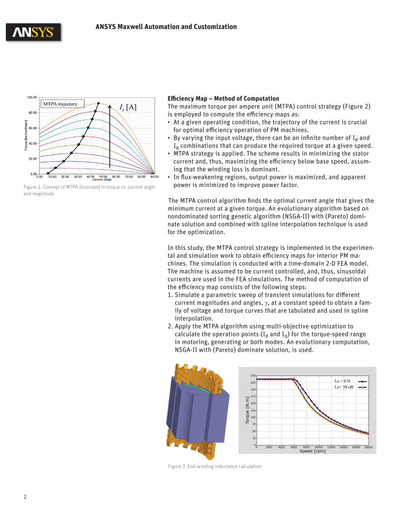
Effi ciency Map – Method of ComputationThe maximum torque per ampere unit (MTPA) control strategy (Figure 2) is employed to compute the effi ciency maps as:• At a given operating condition, the trajectory of the current is crucial
for optimal effi ciency operation of PM machines.• By varying the input voltage, there can be an infi nite number of Id and
Iq combinations that can produce the required torque at a given speed.• MTPA strategy is applied. The scheme results in minimizing the stator
current and, thus, maximizing the effi ciency below base speed, assum-ing that the winding loss is dominant.
• In fl ux-weakening regions, output power is maximized, and apparent power is minimized to improve power factor.
The MTPA control algorithm fi nds the optimal current angle that gives the minimum current at a given torque. An evolutionary algorithm based on nondominated sorting genetic algorithm (NSGA-II) with (Pareto) domi-nate solution and combined with spline interpolation technique is used for the optimization.
In this study, the MTPA control strategy is implemented in the experimen-tal and simulation work to obtain effi ciency maps for interior PM ma-chines. The simulation is conducted with a time-domain 2-D FEA model. The machine is assumed to be current controlled, and, thus, sinusoidal currents are used in the FEA simulations. The method of computation of the effi ciency map consists of the following steps:1. Simulate a parametric sweep of transient simulations for diff erent
current magnitudes and angles, γ, at a constant speed to obtain a fam-ily of voltage and torque curves that are tabulated and used in spline interpolation.
2. Apply the MTPA algorithm using multi-objective optimization to calculate the operation points (Id and Iq) for the torque-speed range in motoring, generating or both modes. An evolutionary computation, NSGA-II with (Pareto) dominate solution, is used.
Figure 2. Concept of MTPA illustrated in torque vs. current angle and magnitude
Figure 3. End-winding inductance calculation
2
3. Run the fi nal simulations using the calculated operation points found with the MTPA. These operation points are simulated at the whole torque-speed range to compute the core loss and eddy-current magnet loss at diff erent supply frequencies.
4. Compute the effi ciency from the output power and total losses that include winding loss, core loss, eddy-current loss in the magnets and mechanical loss.
The method off ers the following advantages:1. Requires only voltage and current limits as inputs and automatically
applies the MTPA algorithm and computes the optimal control angle at the whole torque-speed range accordingly
2. Requires running only a parametric sweep of the current and current angle at a single speed. The torque is assumed to be independent of the speed in current-fed machines. The voltage is assumed to satisfy constant volts per hertz relation. These are considered to be valid as-sumptions in synchronous machines in which the losses, including core loss and eddy-current loss, have minimal infl uence on the torque and back emf production.
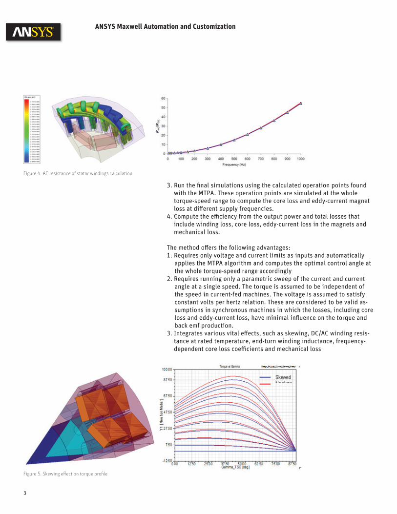
3. Integrates various vital eff ects, such as skewing, DC/AC winding resis-tance at rated temperature, end-turn winding inductance, frequency-dependent core loss coeffi cients and mechanical loss
Figure 4. AC resistance of stator windings calculation
Figure 5. Skewing eff ect on torque profi le
ANSYS Maxwell Automation and Customization
3
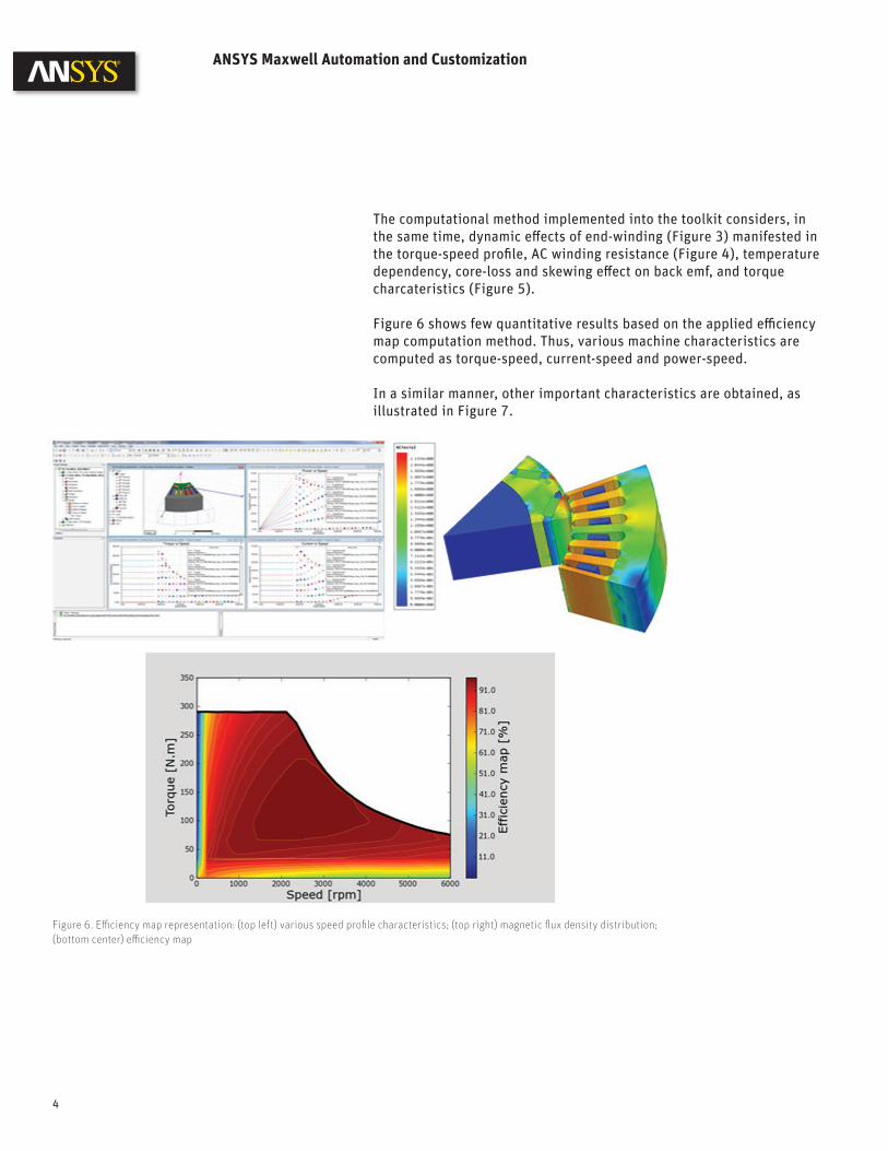
The computational method implemented into the toolkit considers, in the same time, dynamic eff ects of end-winding (Figure 3) manifested in the torque-speed profi le, AC winding resistance (Figure 4), temperature dependency, core-loss and skewing eff ect on back emf, and torque charcateristics (Figure 5).
Figure 6 shows few quantitative results based on the applied effi ciency map computation method. Thus, various machine characteristics are computed as torque-speed, current-speed and power-speed.
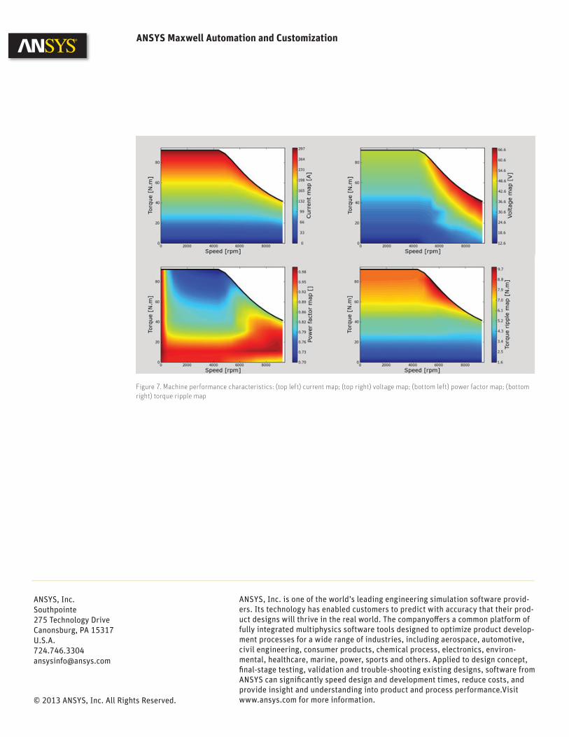
In a similar manner, other important characteristics are obtained, as illustrated in Figure 7.
ANSYS Maxwell Automation and Customization
Figure 6. Effi ciency map representation: (top left) various speed profi le characteristics; (top right) magnetic fl ux density distribution; (bottom center) effi ciency map
4
ANSYS, Inc. is one of the world’s leading engineering simulation software provid-ers. Its technology has enabled customers to predict with accuracy that their prod-uct designs will thrive in the real world. The companyoff ers a common platform of fully integrated multiphysics software tools designed to optimize product develop-ment processes for a wide range of industries, including aerospace, automotive, civil engineering, consumer products, chemical process, electronics, environ-mental, healthcare, marine, power, sports and others. Applied to design concept, fi nal-stage testing, validation and trouble-shooting existing designs, software from ANSYS can signifi cantly speed design and development times, reduce costs, and provide insight and understanding into product and process performance.Visit www.ansys.com for more information.
ANSYS, Inc.Southpointe275 Technology DriveCanonsburg, PA [email protected]
© 2013 ANSYS, Inc. All Rights Reserved.
Figure 7. Machine performance characteristics: (top left) current map; (top right) voltage map; (bottom left) power factor map; (bottom right) torque ripple map
ANSYS Maxwell Automation and Customization